Audio Technica ATWR220 Communications Receiver User Manual P51672 Freeway 220 OM
Audio-Technica Corporation Communications Receiver P51672 Freeway 220 OM
UserManual.wiki
>
Audio Technica
>
ATWR220 User Manual
users manual
Navigation menu
Upload a User Manual
Namespaces
Wiki Guide
HTML
PDF
Info
Views
User Manual
Discussion / Help
Navigation
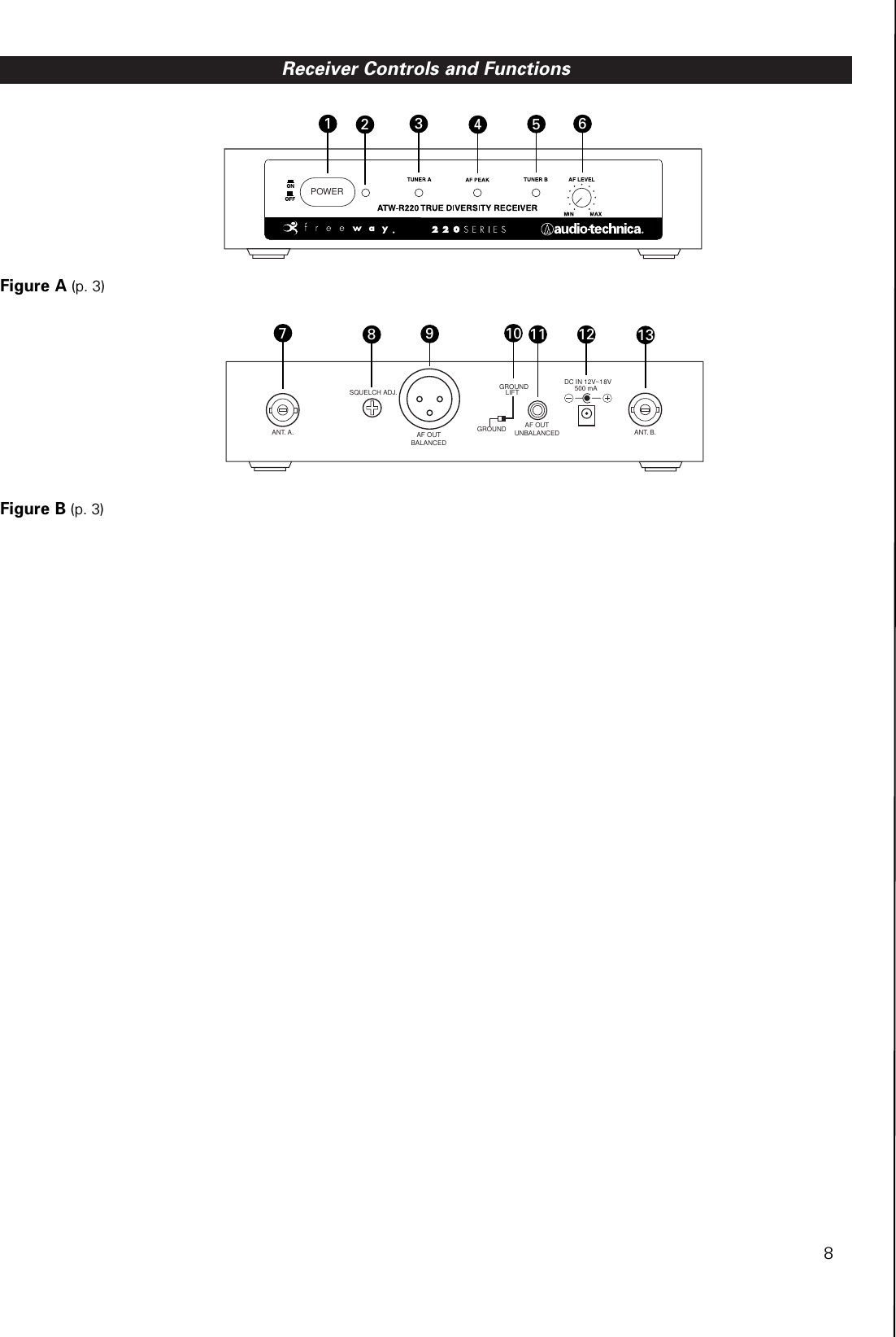
![Receiver Installation3LocationFor best operation the receiver should be at least 3' (1 m)above the ground and at least 3' (1 m) away from a wall ormetal surface to minimize reflections. Keep the receiver antennas away from noise sources such as digital equipment,motors, automobiles and neon lights, as well as away fromlarge metal objects. In multi-channel systems, positionreceivers at least 3' (1 m) apart and keep operating transmit-ters at least 6' (2 m) from the receivers to help assure maximum RF performance.Output ConnectionThere are two audio outputs on the back of the receiver: balanced (160 mV) and unbalanced (280 mV). Use shieldedaudio cable for the connection between the receiver and themixer. If the input of the mixer is a 1/4" jack, connect a cablefrom the 1/4" unbalanced audio output on the back of the receiver to the mixer. If the input of the mixer is an XLR-typeinput, connect a cable from the balanced XLR-type audio output on the back of the receiver to the mixer. The two isolated audio outputs permit simultaneous feeds to both unbalanced and balanced inputs. For example, both aguitar amp and a mixer can be driven by the receiver. Front Panel Controls and Functions (Fig. A)1. POWER SWITCH: Press power switch in to turn on2. POWER INDICATOR: Lights when power is supplied to the receiver.3. TUNER OPERATION INDICATOR: Indicates which tuner has the better reception and is in operation.4. AF PEAK INDICATOR: Only lights when audio distortion is present at maximum modulation. Not affected by position of AF Level Control. 5. TUNER OPERATION INDICATOR: Indicates which tuner has the better reception and is in operation.6. AF LEVEL CONTROL: Adjusts the level at both audio output jacks.Power ConnectionConnect the included [need number] adapter to the DC powerinput on the back of the receiver. Then plug the adapter into astandard 120 volt 60 Hz AC power outlet.AntennasAttach the antennas to the antenna input jacks.Receiver Controls and FunctionsRear Panel Controls and Functions (Fig. B)7. ANTENNA INPUT JACK: BNC-type antenna connector forTuner “A.” Attach the antenna directly, or extend it with a low-loss antenna cable. 8. SQUELCH CONTROL: Adjusts level of noise-muting circuit (Preset at factory but can be adjusted as circumstances warrant.)9. BALANCED AUDIO OUTPUT JACK: XLRM-type connector. A standard 2-conductor shielded cable can be used to connect the receiver output to a balanced aux-level input on a mixer.10. GROUND LIFT SWITCH: Disconnects the ground pin of the balanced output (9) from ground. Normally, the switch should be to the left (ground connected). If hum caused bya ground loop occurs, slide switch to the right.11. UNBALANCED AUDIO OUTPUT JACK: 1/4" phone jack. Can be connected to an unbalanced aux-level input of a mixer or tape recorder.12. DC POWER INPUT: For the provided [NEED NUMBER] adapter, or other 12-18V DC source. (Receiver requires 500 mA.) [CORRECT?]13. ANTENNA INPUT JACK: BNC-type antenna connector forTuner “B.” Attach the antenna directly, or extend it witha low-loss antenna cable.](https://usermanual.wiki/Audio-Technica/ATWR220/User-Guide-417871-Page-3.png)