Audio Technica M3TM EAR MONITOR SYSTEM-TRANSMITTER User Manual IEM M2 Manual v1 DRAFT
Audio-Technica Corporation EAR MONITOR SYSTEM-TRANSMITTER IEM M2 Manual v1 DRAFT
UserManual.wiki
>
Audio Technica
>
M3TM User Manual
USERS MANUAL
Navigation menu
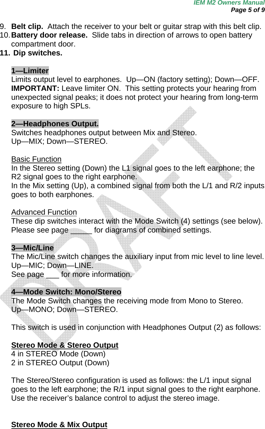
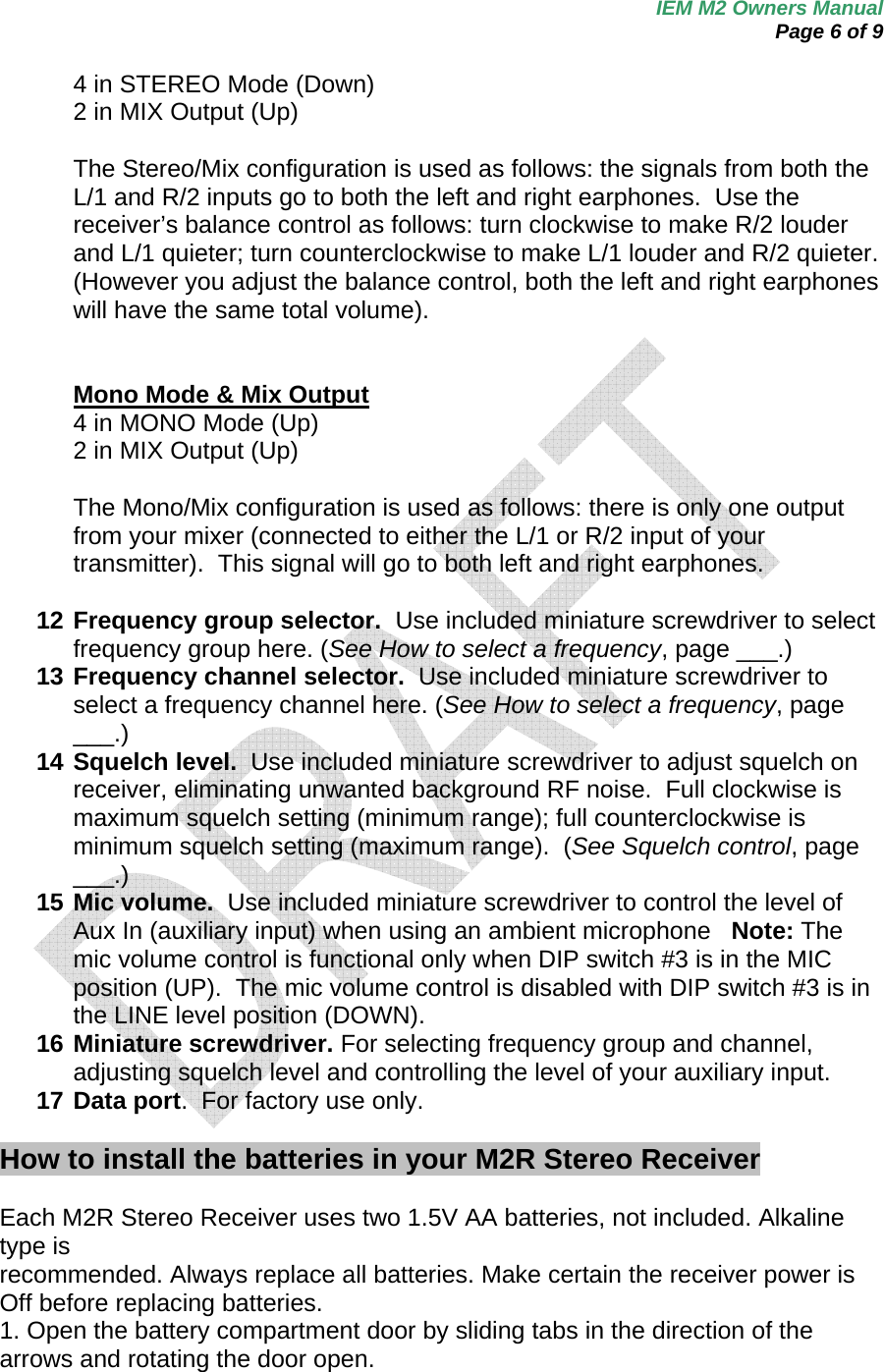
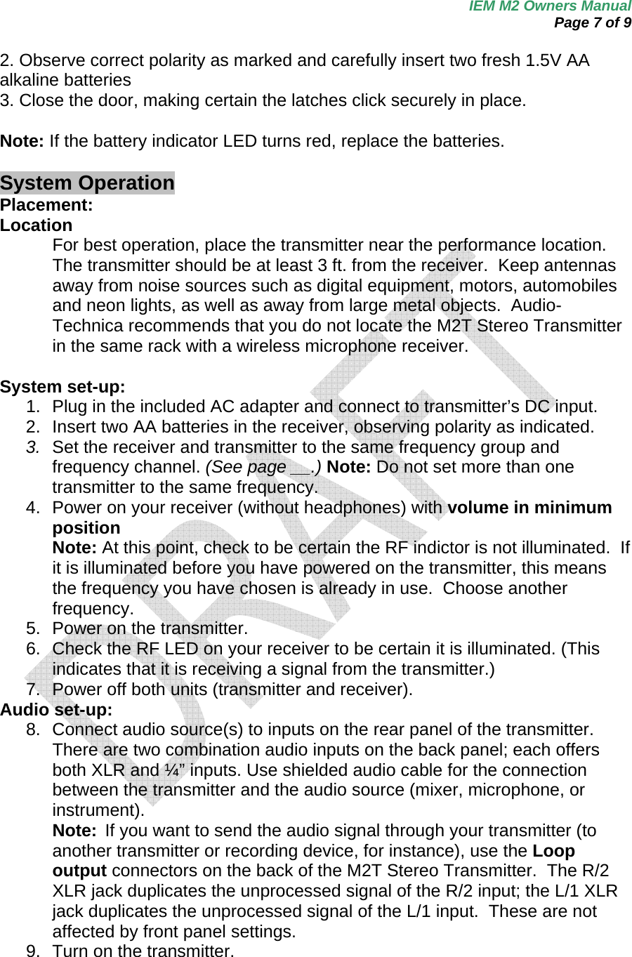
Upload a User Manual
Namespaces
Wiki Guide
HTML
PDF
Info
Views
User Manual
Discussion / Help
Navigation
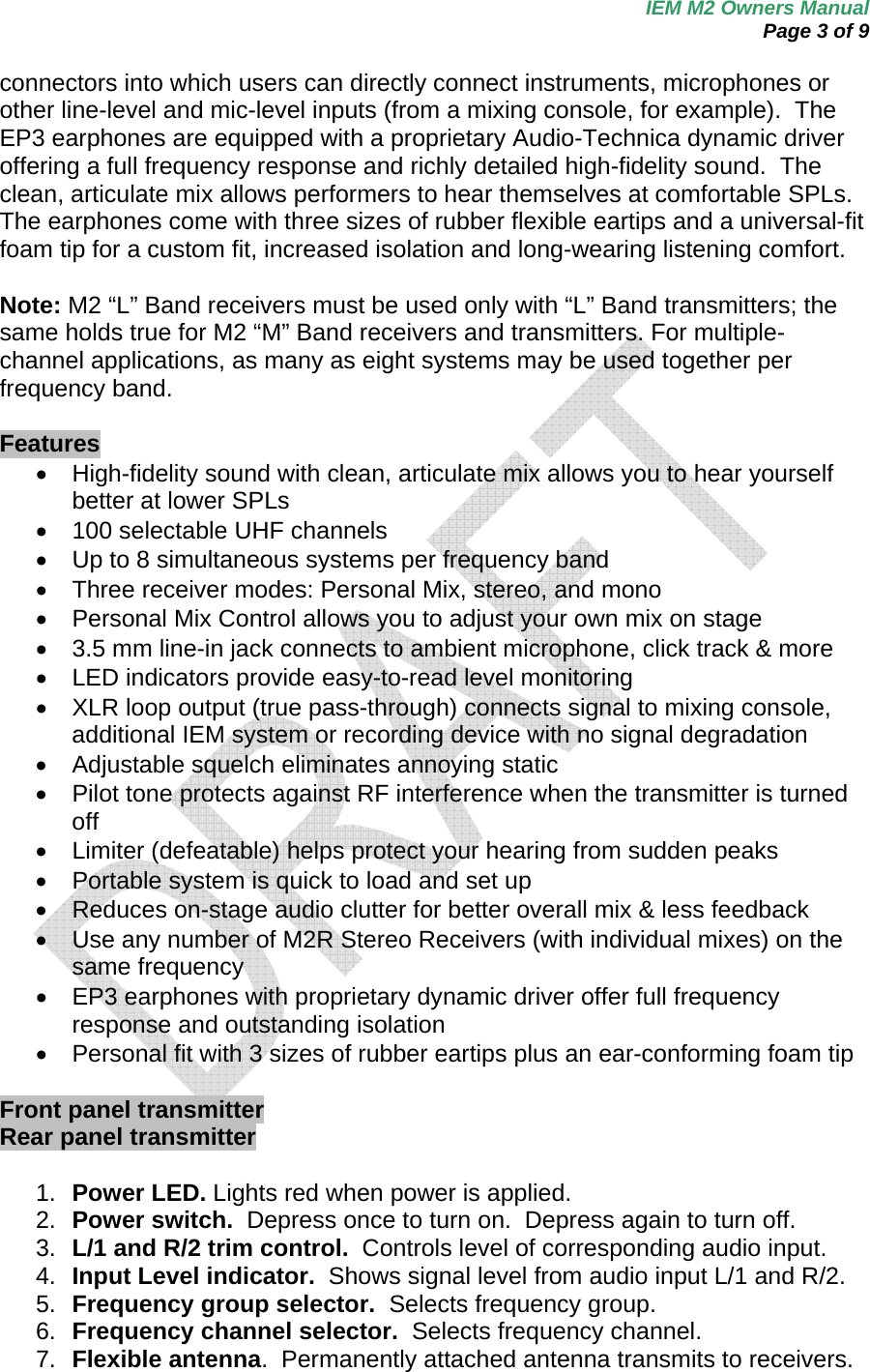
![IEM M2 Owners Manual Page 2 of 9 To prevent damage to your eardrums, never use this system at excessive volume levels. Listening to loud sounds for an extended period may cause temporary or permanent hearing damage. System components [with illustrations] M2R UHF Stereo Receiver M2T UHF Stereo Transmitter with AC adapter EP3 Dynamic Earphones Quick start guide M2R Stereo Receiver M2T Stereo Transmitter 1. Plug in the included AC adapter and connect to transmitter’s DC input. 2. Insert 2 AA batteries in the M2R Stereo Receiver following polarity as indicated. 3. Set M2R Stereo Receiver and M2T Stereo Transmitter to the same frequency. (See page __.) 4. Power on M2R Stereo Receiver with volume in minimum position; power on M2T Stereo Transmitter. Check to see that RF LED on M2R Stereo Receiver is illuminated. 5. Power off receiver and transmitter 6. Connect audio source(s) to inputs on the rear panel of the transmitter. 7. Power on M2T Stereo Transmitter. 8. Adjust attenuator on rear panel of M2T Stereo Transmitter to appropriate level. (See page __.) 9. Adjust trim level on front panel of M2T Stereo Transmitter, if needed. (See page __.) 10. Plug EP3 Dynamic Earphones into earphones locking output jack on M2R Stereo Receiver. NOTE: Do not put the earphones in your ears at this point. 11. Turn on receiver with volume in minimum position. 12. With volume on receiver at minimum position, put earphones into your ears and gradually increase volume until appropriate level is reached. M2 Wireless In-Ear Monitor System—Introduction Thank you for buying the Audio-Technica M2 Wireless In-Ear Monitor System. This feature-rich in-ear monitor system is designed to provide you with comfortable high-fidelity sound on stage. The M2 is a frequency-agile in-ear monitor system designed to make stage monitoring more effective, comfortable, portable, and intelligible. The M2R Stereo Receiver allows the user to create and control his/her own mix on stage with Personal Mix Control that offers independent control of volume and mix at the receiver. The M2T Stereo Transmitter offers two ¼”/XLR combo input](https://usermanual.wiki/Audio-Technica/M3TM/User-Guide-873631-Page-2.png)
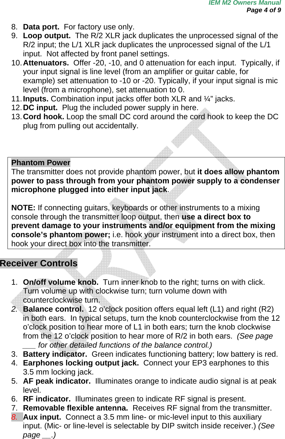
![IEM M2 Owners Manual Page 8 of 9 10. Set the attenuator on rear panel of transmitter to appropriate level. If connecting a mic level source, set the attenuator to 0 dB. If connecting a line-level source, set the attenuator to -10 dB. If Input Level LEDs are consistently red or orange, set the attenuator to -20 dB or turn the trim down for corresponding audio input. 11. Trim levels are set at the factory to the maximum position; adjust if necessary. (See page __.) 12. Plug earphones into jack on receiver. Turn the locking ring clockwise until tight. NOTE: Do not put the headphones in your ears at this point. 13. Turn on receiver with volume in minimum position. 14. With volume on receiver at minimum position, put earphones into your ears and gradually increase volume until appropriate level is reached. How to select a frequency 1. Select a frequency group (A-J) via the Frequency Group Selector on the front panel of the M2T Stereo Transmitter. 2. Next, select a channel (1-10) via the Frequency Channel Selector on the front panel of the M2T Stereo Transmitter. 3. Before turning on your receiver, use the provided screwdriver to set the receiver channel selector switches (see page __) to the same frequency group and channel you have selected on the transmitter. Select frequency groups A-J and channels 1-10. The transmitter may be either on or off when changing channels (frequencies). Each transmitter/receiver system operates on a choice of 100 switch-selected frequencies per band (10 frequencies in 10 frequency groups). Available frequencies are shown in the chart below. In multi-channel systems, always use the same frequency group. Note that M2R Stereo Receiver and M2T Stereo Transmitters operate either in TV channels 38-43, identified as Band L, or in ….. M2 “L” Band transmitters must be used only with “L” Band receivers; the same holds true for all the frequency bands (i.e., always use receivers and transmitters that operate in the same band). The Band marking will be found on the antenna of both the M2T Stereo Transmitter and M2R Stereo Receiver. Note: Because these frequencies are shared with TV broadcasting (depending on country of use), frequency selection is largely dependent upon which TV broadcast channels are in operation where the wireless system is to be used. [frequency chart]](https://usermanual.wiki/Audio-Technica/M3TM/User-Guide-873631-Page-8.png)