Audio Technica R2100D Wireless Microphone Receiver User Manual P51716 2000 Series OM Japan
Audio-Technica Corporation Wireless Microphone Receiver P51716 2000 Series OM Japan
UserManual.wiki
>
Audio Technica
>
R2100D User Manual
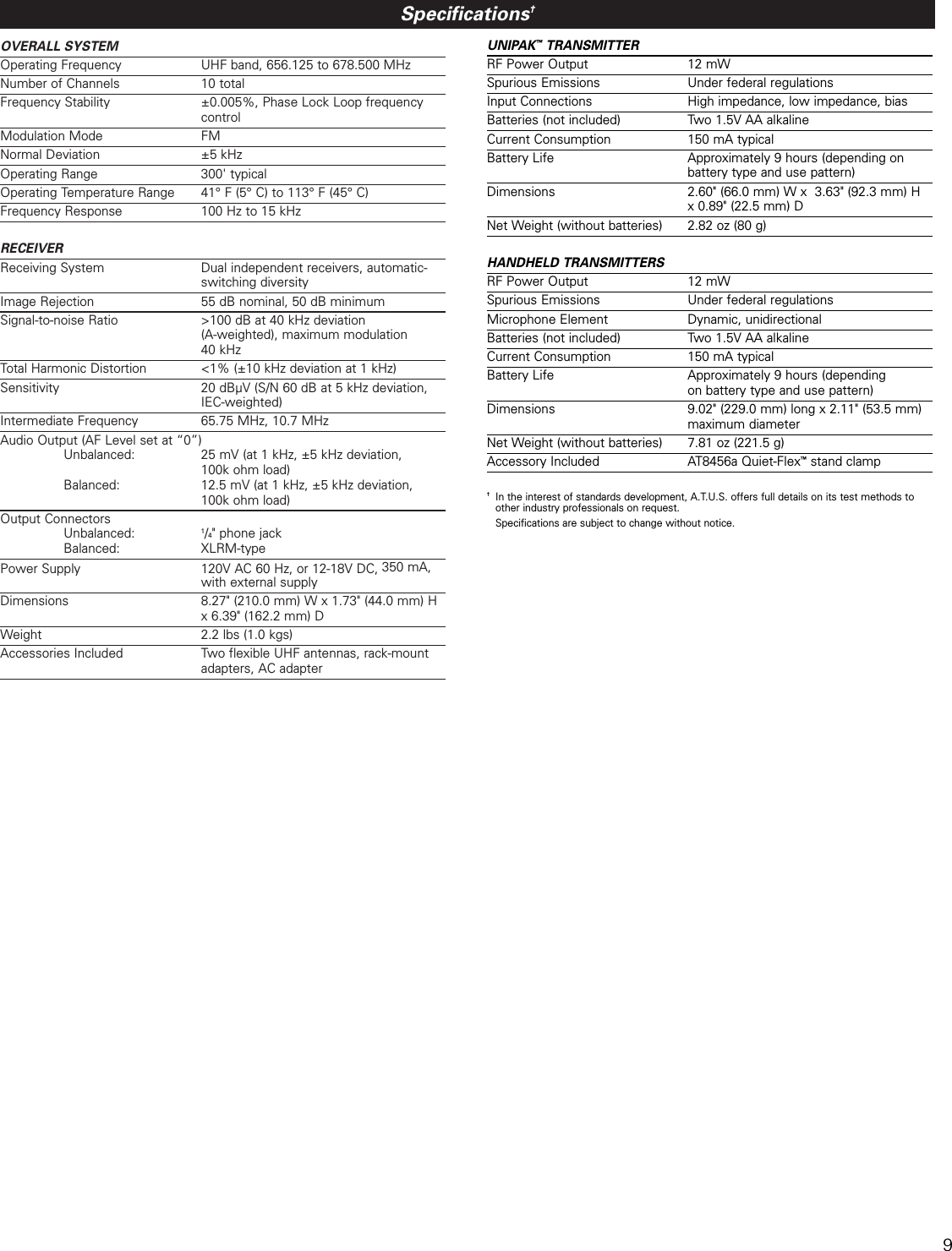
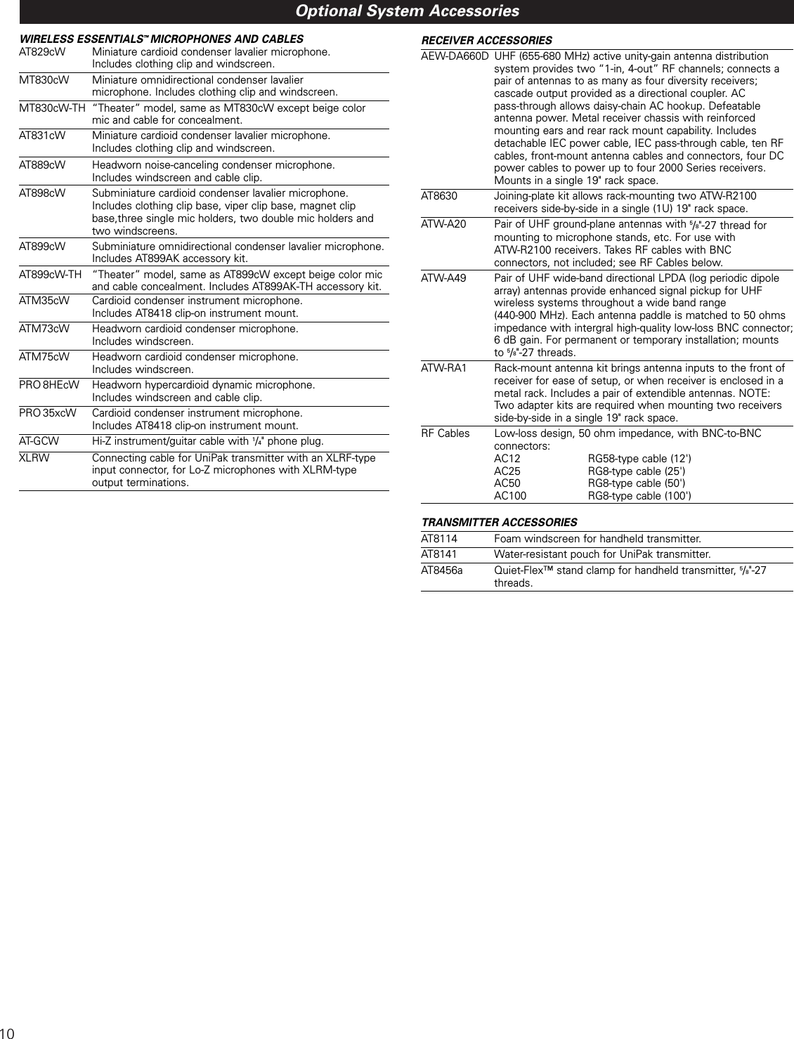
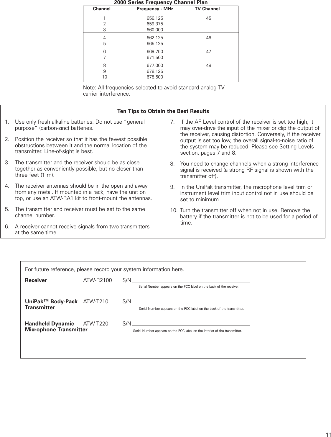
USERS MANUAL
Navigation menu
Upload a User Manual
Namespaces
Wiki Guide
HTML
PDF
Info
Views
User Manual
Discussion / Help
Navigation