Audio Technica R3100C UHF RECEIVER User Manual P51733 3000 Series OM
Audio-Technica Corporation UHF RECEIVER P51733 3000 Series OM
UserManual.wiki
>
Audio Technica
>
R3100C User Manual
users manual
Navigation menu
Upload a User Manual
Namespaces
Wiki Guide
HTML
PDF
Info
Views
User Manual
Discussion / Help
Navigation
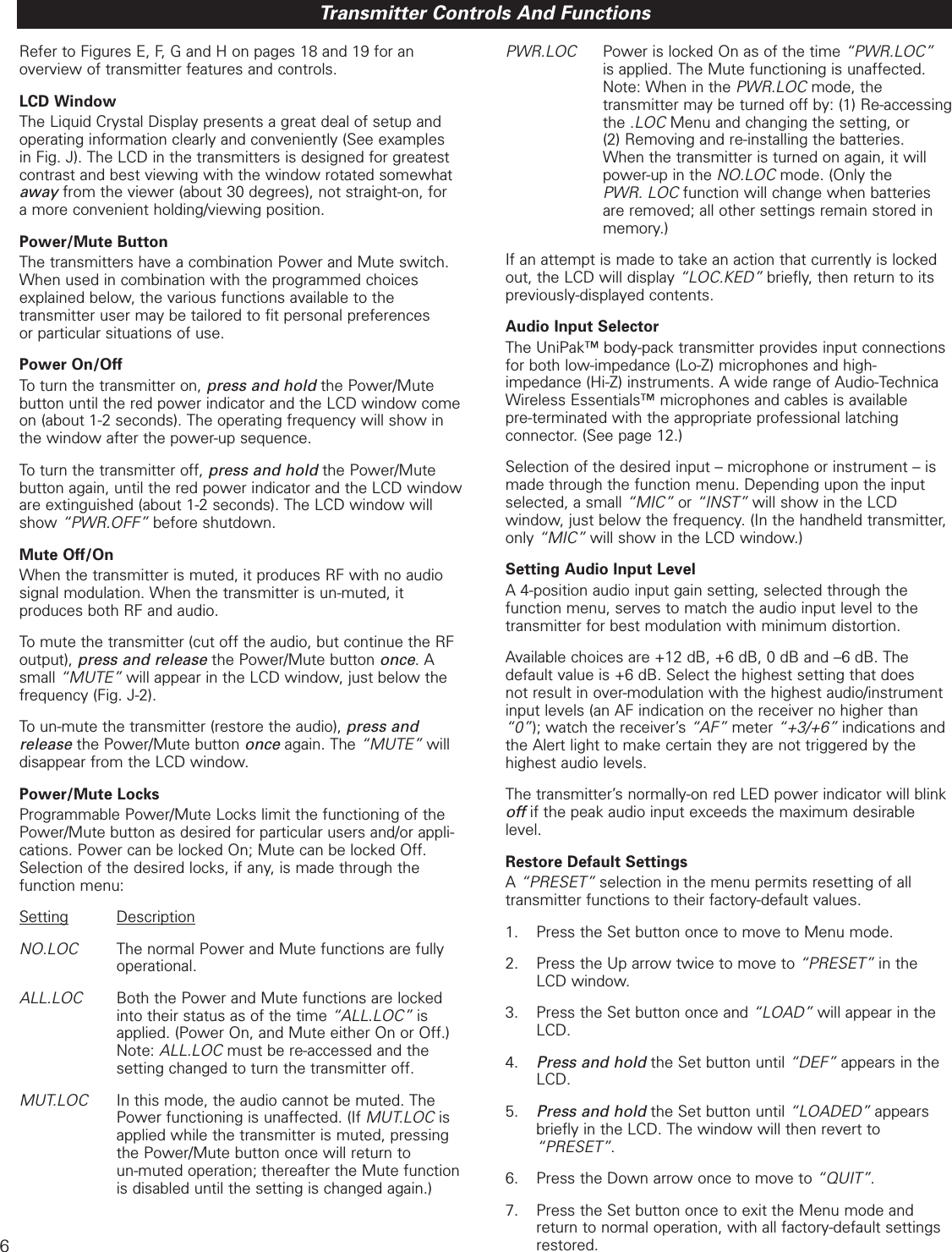
![16Receiver is not on (LCD window does not light).• Receiver Power switch is not pressed in.• Small DC power cord from included in-line power supply is not plugged into jack on back of receiver. (Use the cord hook to secure it.)• The in-line power supply is not plugged into AC power outlet.• AC power is not present at the AC outlet.Receiver is on (LCD window lights) •No sound •Alert light is OFF:✓“RF”, “AF”and “BATT” legends do not appear in LCD…• Receiver is in the Menu mode. [See p. 4.]✓“RF”and "AF"level meters both show good signals.• AF Level control on back of receiver not turned up (clockwise). [See p. 4.]Note: If the “AF”level meter shows a good signal on the receiver when the transmitter is receiving audio input, and the AF Level control is turned up, then the problem is in connections to or control settings on the mixer, amplifier, etc.✓Only “RF”level meter shows good signal; no “AF”signal.• No sound input to mic.• ATW-T310 body-pack only: Wrong input selected (“INST”or “MIC”). [See p. 6.]Receiver is on (LCD window lights) •No sound •Alert light is ON:✓“RF”, “AF”and “BATT”legends do not appear in LCD, and LCD is flashing…• Receiver is in the Edit mode. [See p. 4.]✓“RF”and “AF”level meters both show good signals.• The transmitter audio level is too high (“+3”/”+6”on receiver). [See p. 9.]• Batteries may be weak. (Check “BATT”fuel gauge.)✓Only “RF”level meter shows good signal; no “AF”signal.• Transmitter may be muted. (Note: Normally it takes several seconds for the Alert light to turn off/on after the transmitter mute is switched off/on.) [See p. 5.]✓Neither the “RF”nor the “AF”level meter shows any signal.• Receiver antennas not connected.• Transmitter is turned off.• Transmitter batteries are dead or missing.• Transmitter is set to a different frequency.• Transmitter and receiver not in same Band (C/D).Troubleshooting GuideReceiver is on (LCD window lights) •Distorted sound •Alert light is ON:✓“RF”and/or “AF”level meters may show good signals.• The transmitter audio level is too high (“+3”/”+6”on receiver). [See p. 9.]• Received RF level may be too low (only one or two bars).• Batteries may be weak; check “BATT”fuel gauge. (Sound may or may not be distorted.)Momentary loss of sound/noisy sound as transmitter ismoved around performing area.• Transmitter and receiver antennas not in line-of-sight (or perhaps too far apart). Adjust positions of units so they are visible to each other/closer together; use remote antennas located closer to the transmitter location.• Signal blockage or interference from large metal objects, other wireless units located too close and/or on incompatible frequencies, computer or lighting equipment.• Squelch setting may be set “tighter” than it needs to be. (Recommended squelch setting is the minimum/default value, 15 dB.) [See p. 5.]Tip: Use the Meter Hold function to help identify and resolve (or at least avoid) RF problem locations. [See p. 5.]With transmitter on, received signal is noisy or containsextraneous sounds.• Batteries may be weak. Check “BATT”fuel gauge and “RF”meter level.• Local TV transmissions on this frequency.• Nearby sources of RF interference, such as computers, lighting equipment, etc.• Two transmitters may be operating on the same frequency. Locate and turn one off or change its frequency.• In multiple-system use, two (or more) incompatible frequencies may have been selected.](https://usermanual.wiki/Audio-Technica/R3100C/User-Guide-479684-Page-16.png)