Audio Technica RP32 Studio Broadcast UWB Wireless Microphone System User Manual Studio Broadcast System
Audio-Technica Corporation Studio Broadcast UWB Wireless Microphone System Studio Broadcast System
Contents
- 1. User Manual - OM
- 2. User Manual - RP32
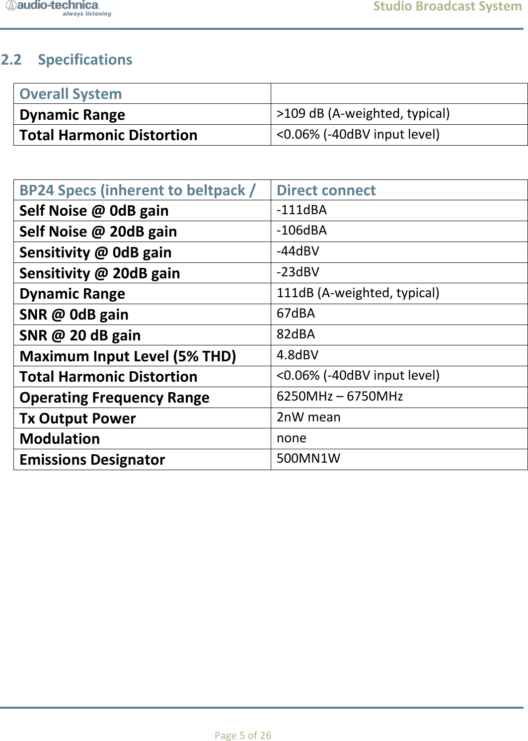
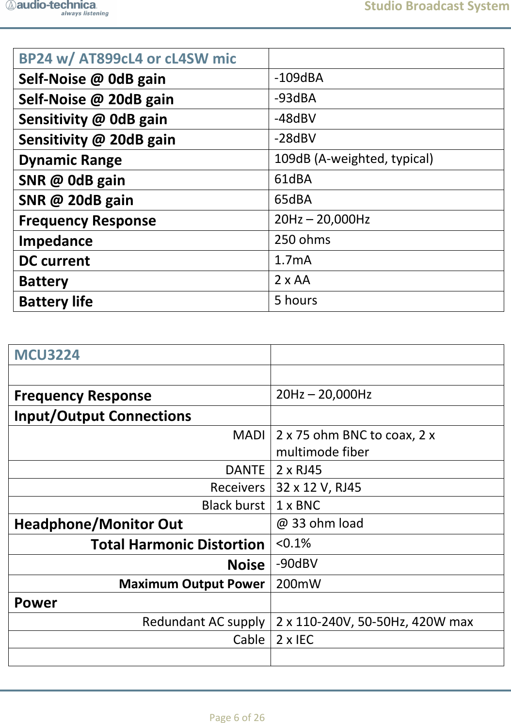
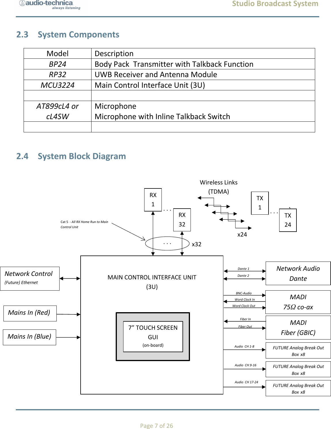
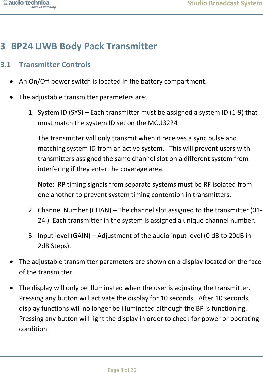
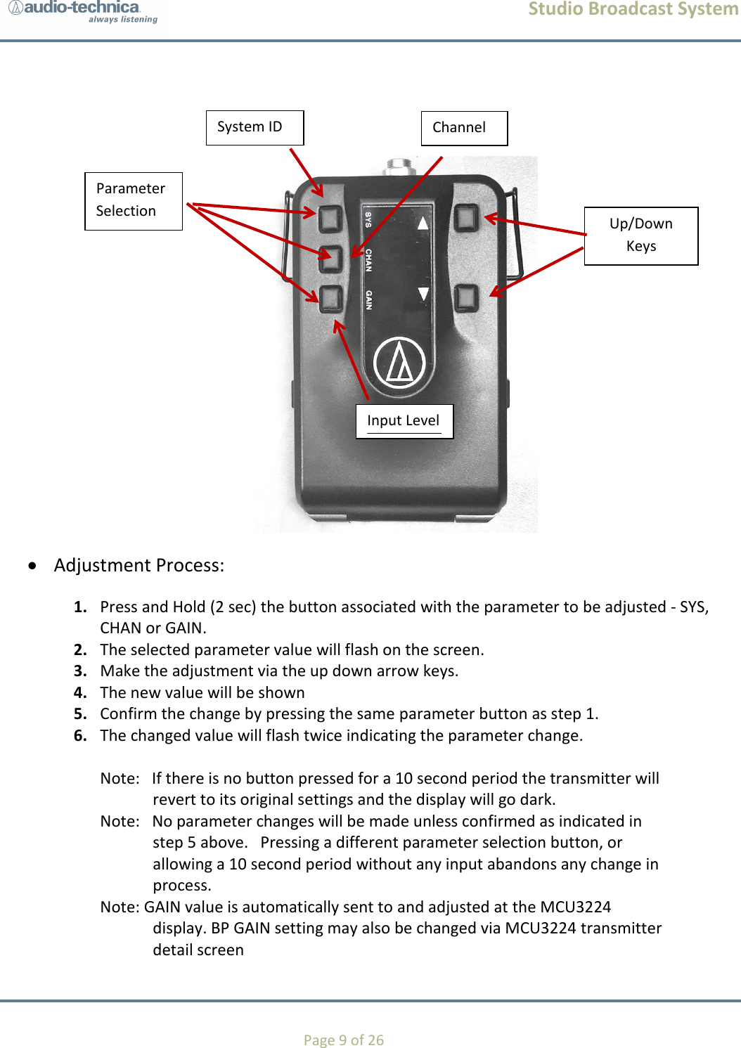
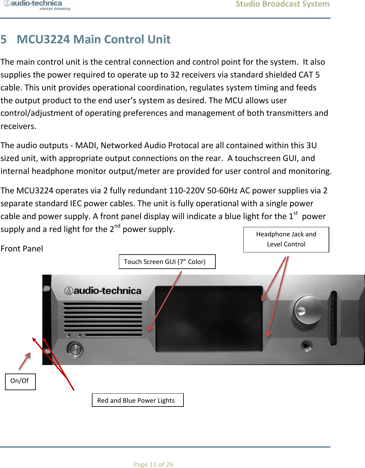
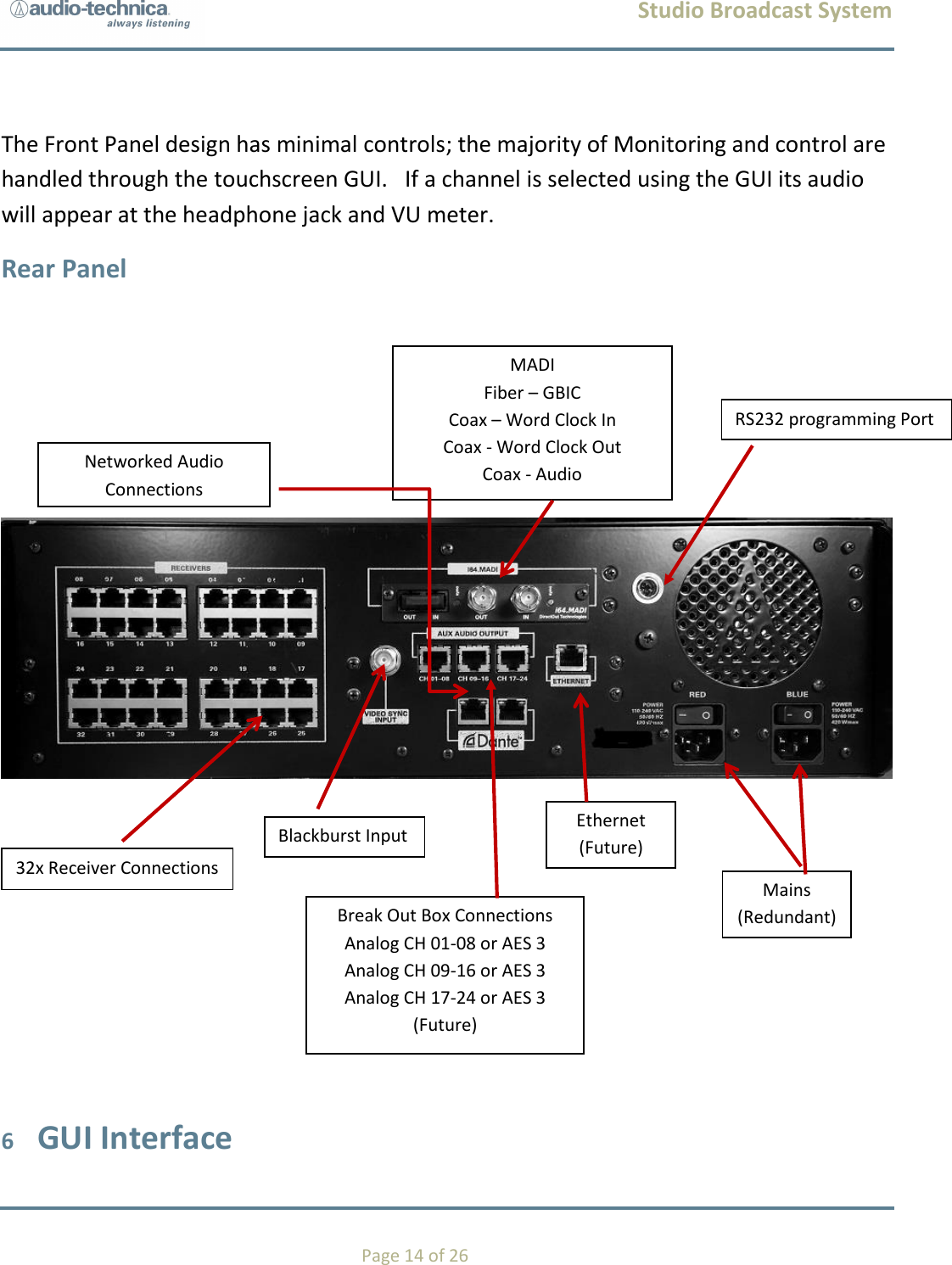
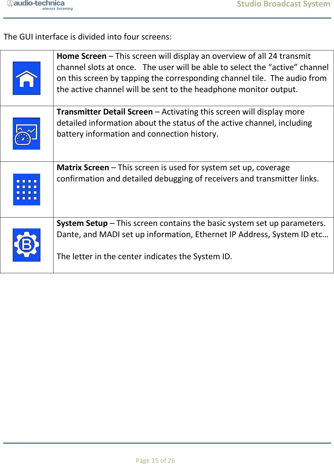
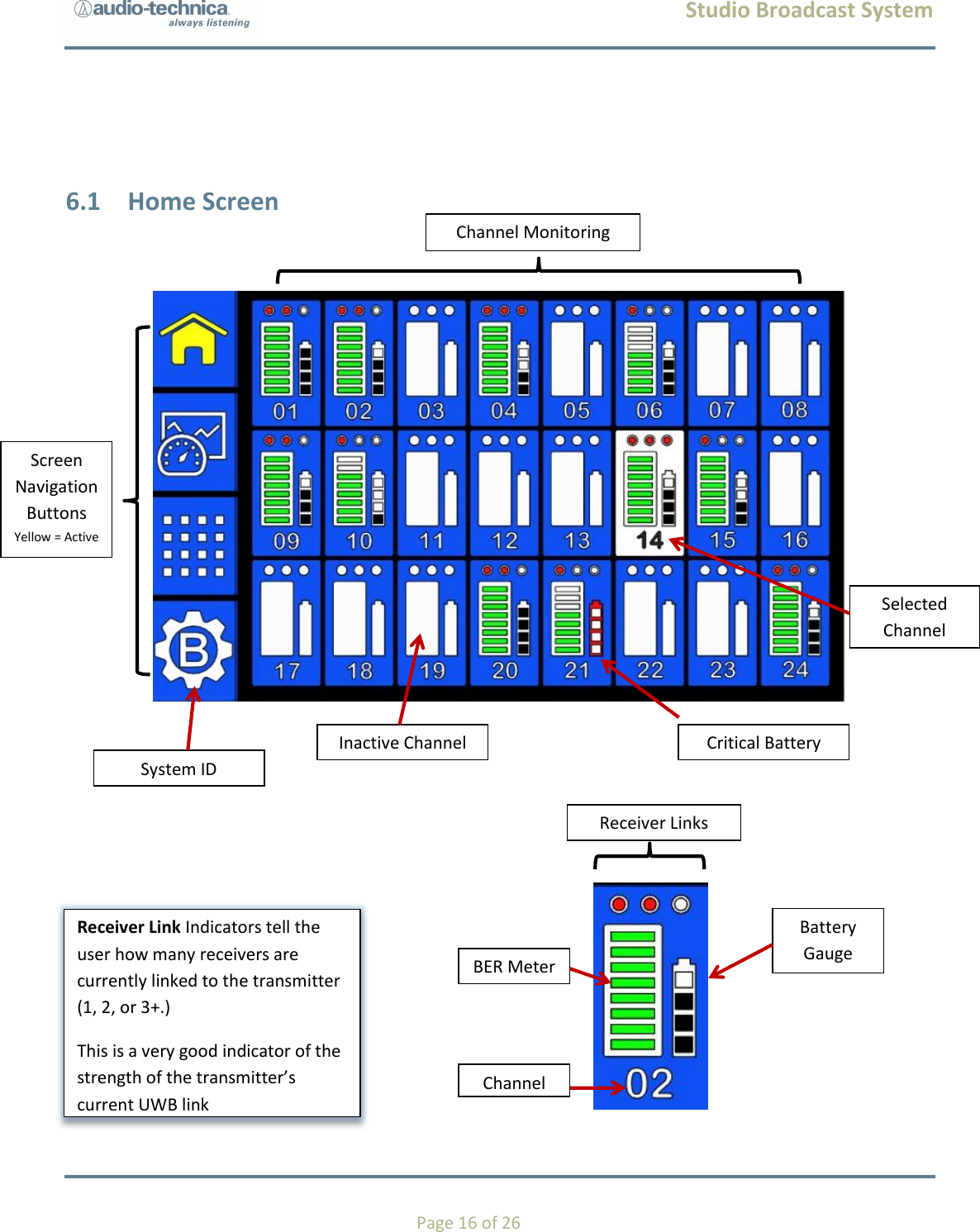
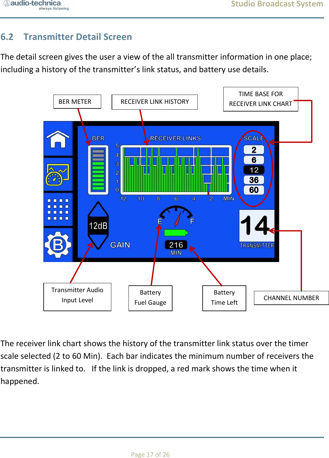
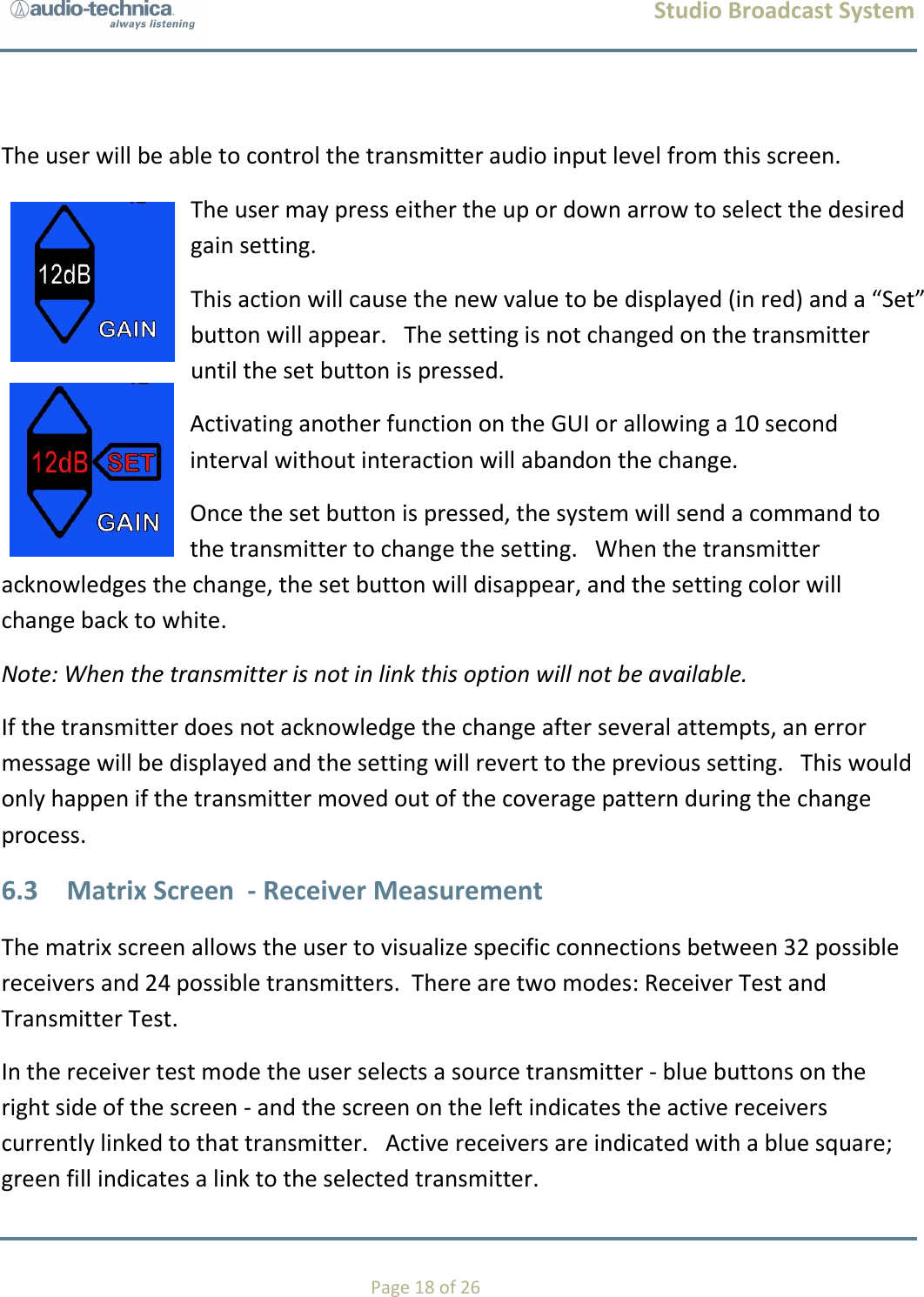
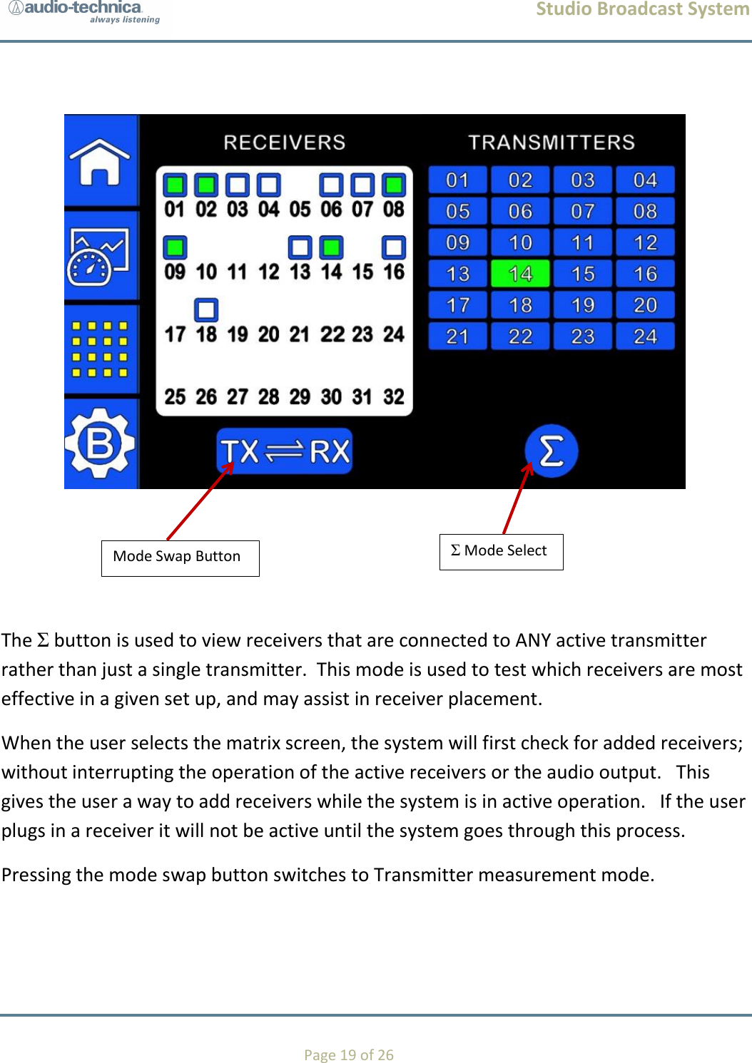
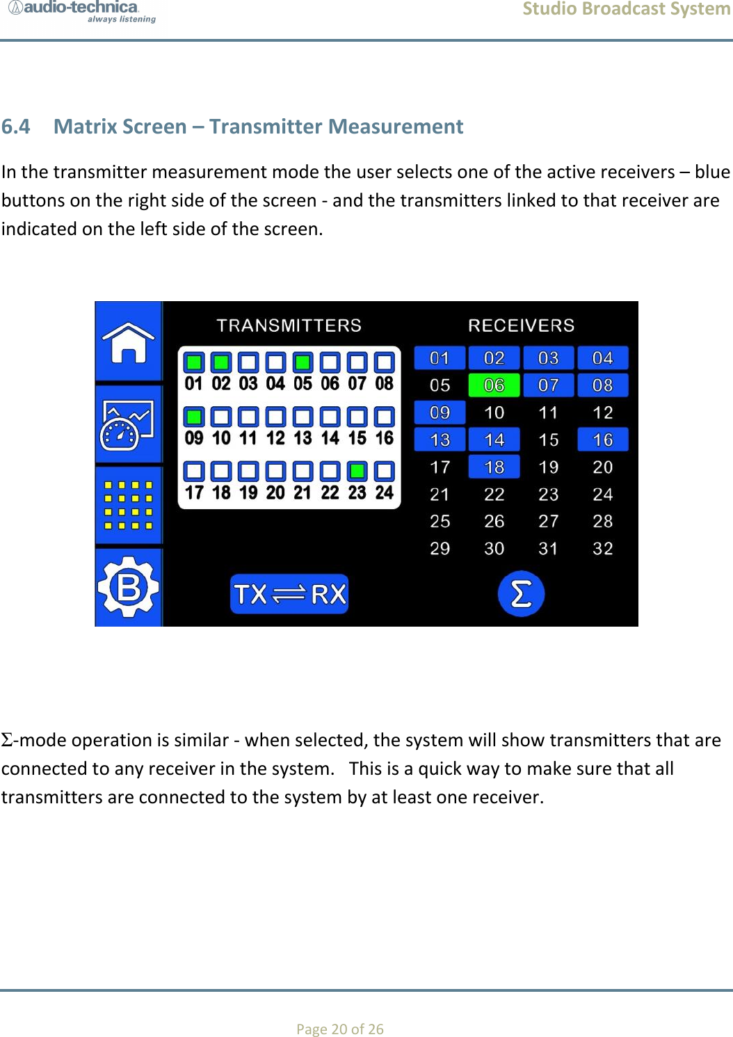
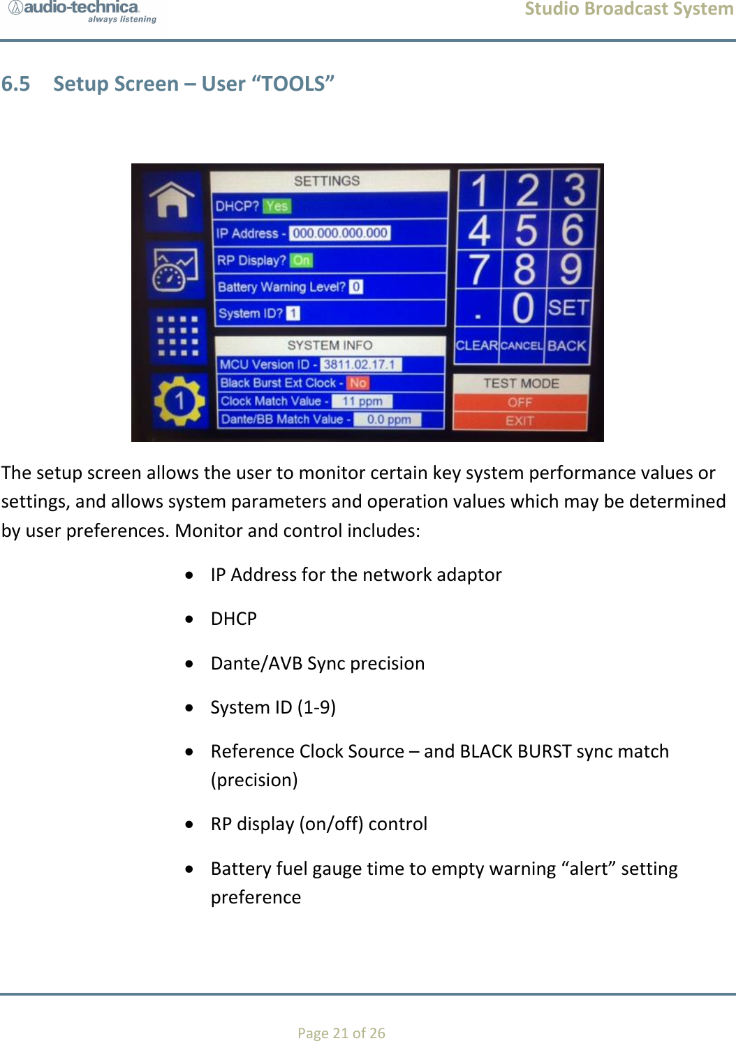
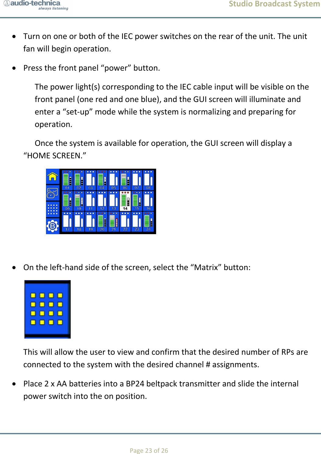
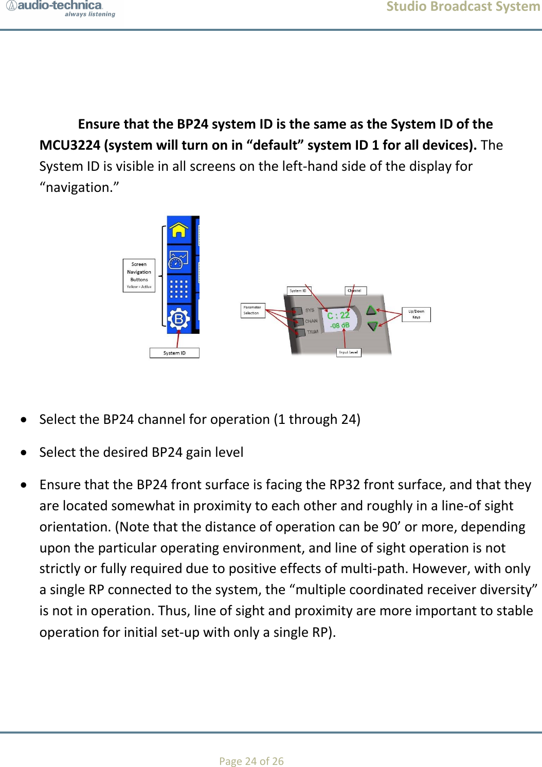
User Manual - OM