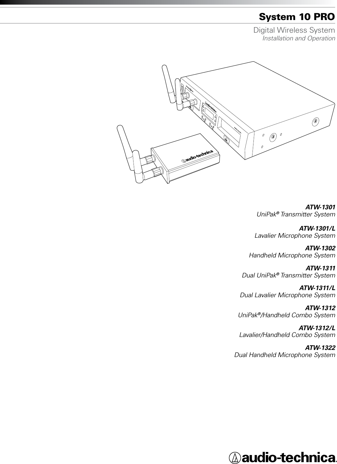
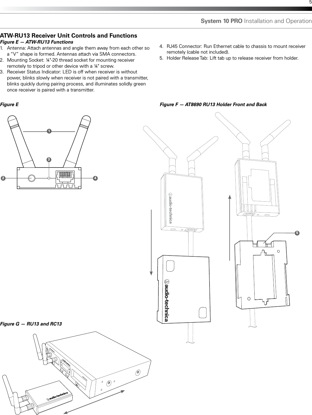
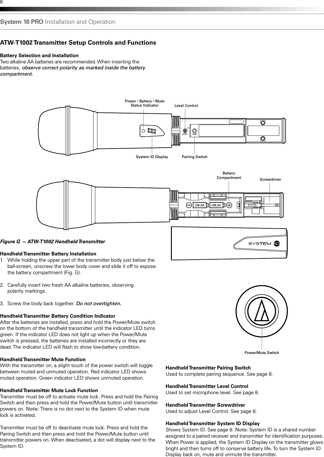
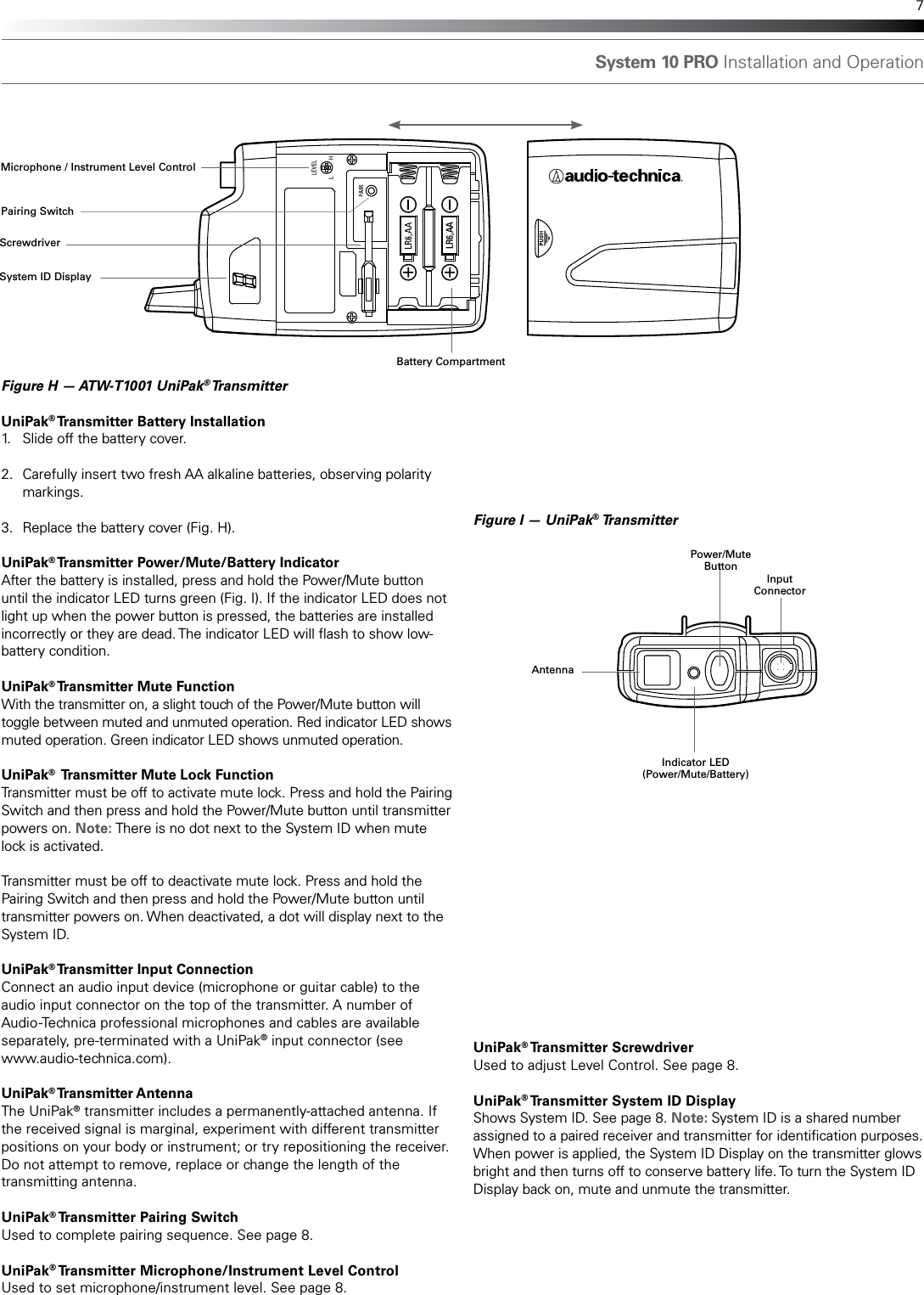
Audio Technica RU13 Wireless Receiver Unit User Manual

Audio-Technica Corporation Wireless Receiver Unit

User Manual

System 10 PRODigital Wireless SystemInstallation and OperationATW-1301UniPak® Transmitter  SystemATW-1301/LLavalier Microphone SystemATW-1302Handheld Microphone SystemATW-1311 Dual UniPak® Transmitter  SystemATW-1311/L Dual Lavalier Microphone SystemATW-1312 UniPak®/Handheld Combo SystemATW-1312/L Lavalier/Handheld Combo SystemATW-1322Dual Handheld Microphone System**NOT A FINAL**Work In Progress
System 10 PRO Installation and Operation2attaching it at the belt, rather than in a shirt pocket where it may be immediately adjacent to the medical device. Note also that any medical-device disruption will cease when the RF transmitting source is turned off. Please contact your physician or medical-device provider if you have any questions, or experience any problems with the use of this or any other RF equipment.Important Safety Instructions1.  Read these instructions.2.  Keep these instructions.3.  Heed all warnings.4.  Follow all instructions.5.  Do not use this apparatus near water.6.  Clean only with a dry cloth.7.  Install in accordance with the manufacturer’s instructions.8.  Do not install near any heat sources such as radiators, heat registers, stoves, or other apparatus (including ampliers) that produce heat.9.  Unplug this apparatus during lightning storms or when unused for long periods of time.10.  Refer all servicing to qualied service personnel. Servicing is required when the apparatus has been damaged in any way, such as power-supply cord or plug is damaged, liquid has been spilled or objects have fallen into the apparatus, the apparatus has been exposed to rain or moisture, does not operate normally, or has been dropped.Thank you for choosing an Audio-Technica System 10 PRO Rack-Mount digital wireless system. You have joined thousands of other satised customers who have chosen our products because of their quality, performance and reliability. This wireless microphone system is the successful result of years of design and manufacturing experience. Audio-Technica’s System 10 PRO Rack-Mount is a digital wireless system designed to provide rock-solid performance along with easy setup and clear, natural sound quality. Featuring a dual-receiver chassis and remote-mount receiver unit capability, System 10 PRO Rack-Mount is available in various handheld and body-pack congurations. Operating in the 2.4 GHz range, far from TV and DTV interference, System 10 PRO Rack-Mount offers extremely easy operation and instantaneous channel selection. Up to ten channels may be used together without any frequency coordination problems or group selection issues.  System 10 wireless ensures clear communications by providing three levels of diversity assurance: frequency, time, and space. Frequency Diversity sends the signal on two dynamically allocated frequencies for interference-free communication. Time Diversity sends the signal in multiple time slots to maximize immunity to multi-path interference.  Finally, Space Diversity uses two antennas on each transmitter and receiver to maximize signal integrity.Each conguration of the System 10 PRO digital wireless system includes a rack-mountable receiver chassis with two receiver unit docks. Depending on the conguration, the system will also include one or two receiver units that may be docked in the chassis or mounted remotely, and one or two transmitters of either the handheld microphone or body-pack style (or one of each). Some congurations also include one or two lavalier mics that attach to the body-pack transmitters. Up to ve chassis (10 receiver units) can be linked with the included RJ12 cable to allow for simultaneous use of all receivers and increased stability of the multi-channel system. Because System 10 packaging is designed to hold all versions of  the system, some compartments in the carton may be intentionally  left empty.The ATW-R1300 includes a switching power supply that automatically adapts to changes in mains voltage.  The versatile ATW-T1001 UniPak® body-pack transmitter has both a high-impedance input for instruments, and a low-impedance input with bias connection for use with dynamic and electret condenser microphones. The ATW-T1002 handheld transmitter features a unidirectional dynamic microphone element.Both the body-pack and handheld transmitters use internal AA batteries and have Power/Mute switches and input Trim (level) adjustments. CAUTION  RISK OF ELECTRIC SHOCK   DO NOT OPENWARNING: TO REDUCE THE RISK OF FIRE OR ELECTRIC SHOCK, DO NOT REMOVE SCREWS. NO USER-SERVICEABLE PARTS INSIDE.REFER SERVICING TO QUALIFIED SERVICE PERSONNEL.WARNING: TO REDUCE THE RISK OF FIRE OR ELECTRIC SHOCK, DO NOT EXPOSE THE APPLIANCE TO RAIN OR MOISTURE.CERTIFICATION: THIS DEVICE COMPLIES WITH PART 15 OF THE FCC RULES. THIS DEVICE COMPLIES WITH INDUSTRY CANADA LICENSE-EXEMPT RSS STANDARD(S). OPERATION IS SUBJECT TO THE FOLLOWING TWO CONDITIONS: (1) THIS DEVICE MAY NOT CAUSE HARMFUL INTERFERENCE, AND (2) THIS DEVICE MUST ACCEPT ANY INTERFERENCE RECEIVED, INCLUDING INTERFERENCE THAT MAY CAUSE UNDESIRED OPERATION.Cet appareil est conforme à la/aux norme(s) CNR exempte(s) de licence d’Industrie Canada. Son fonctionnement est soumis aux deux conditions suivantes : (1) cet appareil ne doit pas causer d’interférence et (2) cet appareil doit accepter toutes les interférences, y compris celles susceptibles de provoquer un fonctionnement non souhaité.Under Industry Canada regulations, this radio transmitter may only operate using an antenna of a type and maximum (or lesser) gain approved for the transmitter by Industry Canada. To reduce potential radio interference to other users, the antenna type and its gain should be so chosen that the equivalent isotropically radiated power (e.i.r.p.) is not more than that necessary for successful communication.Conformément à la réglementation d'Industrie Canada, le présent émetteur radio peut fonctionner avec une antenne d'un type et d'un gain maximal (ou inférieur) approuvé pour l'émetteur par Industrie Canada. Dans le but de réduire les risques de brouillage radioélectrique à l'intention des autres utilisateurs, il faut choisir le type d'antenne et son gain de sorte que la puissance isotrope rayonnée équivalente (p.i.r.e.) ne dépasse pas l'intensité nécessaire àl'établissement d'une communication satisfaisante.WARNING: Changes or modications not expressly approved in writing by Audio-Technica may void the user’s authority to operate this equipment.RF Exposure Statement: This transmitter must not be co-located or operated in conjunction with any other antenna or transmitter used in other systems. The ATW-T1001, ATW-T1002 and ATW-RU13 complies with FCC/IC radiation exposure limits set forth for an uncontrolled environment and meets the FCC radio frequency (RF) Exposure Guidelines and RSS-102 of the IC radio frequency (RF) Exposure rules. This equipment has very low levels of RF energy that it deemed to comply without maximum permissive exposure evaluation. (MPE). But it is desirable that it should be installed and operated keeping the radiator at least 20cm or more away from person’s body. Le ATW-T1001, ATW-T1002 et ATW-RU13 conformes aux limites d’exposition aux rayonnements énoncées pour un environnement non contrôlé et respecte les règles d’exposition aux fréquences radioélectriques (RF) CNR-102 de l’IC. Cet équipement émet une énergie RF très faible qui est considérée conforme sans évaluation de l ’exposition maximale autorisée. Cependant, il est souhaitable qu'il devrait être installé et utilisé en gardant une distance de 20 cm ou plus entre le dispositif rayonnant et le corps.Note: The ATW-RC13 has been tested and found to comply with the limits for a Class B digital device, pursuant to part 15 of the FCC Rules. These limits are designed to provide reasonable protection against harmful interference in a residential installation. This equipment generates, uses and can radiate radio frequency energy and, if not installed and used in accordance with the instructions, may cause harmful interference to radio communications. However, there is no guarantee that interference will not occur in a particular installation. If this equipment does cause harmful interference to radio or television reception, which can be determined by turning the equipment off and on, the user is encouraged to try to correct the interference by one or more of the following measures:-  Reorient or relocate the receiving antenna.-  Increase the separation between the equipment and receiver.-  Connect the equipment into an outlet on a circuit different from that to which the    receiver is connected.-  Consult the dealer or an experienced radio/TV technician for help.This Class B digital apparatus complies with Canadian ICES-003. Cet appareil umerique de la classe B est conforme a la norme NMB-003 du Canada.CAUTION! Electrical shock can result from removal of the receiver chassis cover. Refer servicing to qualied service personnel. No userserviceable parts inside. Do not expose to rain or moisture. The circuits inside the chassis, receivers and transmitters have been precisely adjusted for optimum performance and compliance with federal regulations. Do not attempt to open the chassis, receivers or transmitters. To do so will void the warranty, and may cause improper operation.Notice to individuals with implanted cardiac pacemakers or AICD devices: Any source of RF (radio frequency) energy may interfere with normal functioning of the implanted device. All wireless microphones have low-power transmitters (less than 0.05 watts output) which are unlikely to cause difculty, especially if they are at least a few inches away. However, since a “body-pack” mic transmitter typically is placed against the body, we suggest
DIGITAL 2.4 GHz SYSTEM 10  PROIDONOFFPAIR ID PAIRABPAIRAUDIOPAIRAUDIOSystem 10 PRO Installation and Operation 3InstallationReceiver Unit LocationFor best operation, position receiver unit so it is off the oor, in line of sight of transmitter and away from any large obstructions. Keep the receiver unit away from noise sources such as other digital wireless equipment, microwave ovens, as well as away from large metal objects. Keep System 10 receivers 30' (9 m) away from wireless access points. Output ConnectionThe ATW-R1300 is equipped with two audio outputs for each receiver: a balanced XLR-type output and an unbalanced ¼" TRS phone jack. Use shielded audio cable for the connection between the receiver and the mixer. If the input of the mixer is a ¼" jack, connect a cable from the ¼" unbalanced audio output on the back of the receiver chassis to the mixer. If the input of the mixer is an XLR-type input, connect a cable from the balanced XLR-type audio output on the back of the chassis to the mixer.Power ConnectionConnect the DC plug on the included AC power adapter to the DC power input on the back of the receiver chassis. Secure the cord over the cord hook on the chassis to keep the plug from being accidentally dislodged. Plug the adapter into a standard 120 Volt 60 Hz AC power outlet. The receiver chassis is equipped with a power On/Off switch. Turn the power off when system is not in use, and unplug the power supply if you expect not to use the system for an extended period. AntennasFor best reception, position the removable antennas in the shape of a “V” so that both tilt 45°.Link ConnectionWhen using multiple systems together it is strongly recommended that you link all of the chassis (up to ve) using the RJ12 cable included with each system. (Linking is not necessary if you are using only a single chassis.) Linking creates a much more stable environment in which receivers work together, with all receiving, transmitting and frequency allocation coordinated to prevent audio dropouts and enable simultaneous use of up to 10 channels. See “Linking Systems” on page 9 for more details.ATW-RC13 Receiver Chassis Controls and FunctionsFigure A — Front Panel Controls and Functions1.  Power Switch: Press to turn power on and off.2.  Service Port: For use only by manufacturer or other qualied    service technician.3.  Receiver Unit Docks: Insert individual receivers to use them locally.4.  Receiver Unit Releases: Press to eject receivers.5.  Audio Indicator (one for each receiver): Illuminates green when    sound is received from transmitter, yellow when audio is nearing    peak level, and red when peak level is reached.6.  Pairing Indicator (one for each receiver): Flashes green in pair mode;    illuminates solidly green once transmitter is paired.7.  System ID Select Switch (one for each receiver): Press to cycle    through System ID numbers. (System ID is a shared number    assigned to a paired receiver and transmitter for identication   purposes.)Figure A8.  Pairing Switch (one for each receiver): Press to initiate pairing.9.  System ID Display includes the following:  a. RF Signal Level Indicator (one for each receiver): Shows strength      of the RF signal received from the transmitter  b. System ID (one for each receiver): Shows the System      ID number  c. Transmitter Battery Gauge TX (one for each receiver): Shows      the capacity of the transmitter’s batteries  d. Link Indicator: Shows that the chassis has been linked to      another chassis2931456 7 8dbca
AVOLUMEMIN. MAX.UNBALANCEDGROUNDGROUND LIFTTO EXTERNALATW- RU13BALANCEDLINKOUT IN DC 12V IN500 mAVOLUMEMIN. MAX.UNBALANCEDGROUNDGROUND LIFTTO EXTERNALATW- RU13BALANCEDBSystem 10 PRO Installation and Operation4Figure B, C & D — Rear Panel Controls and Functions1.  RJ45 Connector: Use Ethernet cable (not included) to mount    receiver remotely up to 328' (100 m) from chassis.2.  AF Level (Volume) Control: Adjusts audio output level of both AF    output jacks; maximum output is fully clockwise.3.  Ground Lift Switch: Disconnects the ground pin of the balanced    output jack (5) from ground. Normally, the switch should be to the    left (ground connected). If hum caused by a ground loop occurs,    slide switch to the right (ground lifted).4.  Unbalanced Audio Output Jack: ¼" phone jack. Can be connected    to an unbalanced aux-level input of a mixer, guitar amp or recording   device. 5.  Balanced Audio Output Jack: XLRM-type connector. A standard    2-conductor shielded cable can be used to connect the receiver    output to a balanced microphone-level input on a mixer or    integrated amplier.6.  Receiver Chassis Link IN/OUT Connector: Use included RJ12 cable    to link chassis to another ATW-R1300 chassis. Up to ve chassis (10    receivers) may be linked.7.  Cord Hook: Loop the cord around the cord hook to keep the DC plug    from pulling loose accidentally.8.  Power Input Jack: Connect the DC plug from the included    AC adapter.9.  Rack Mounting Brackets: Attach brackets to the sides of the receiver    chassis using supplied screws.10. Joining Plate: Attach to the bottom of two receiver chassis using    supplied screws.Figure C — Rack Mounting Brackets Figure BDIGITAL 2.4 GHz SYSTEM 10 PROIDPAIRAUDIOPAIRAUDIOONOFFPAIRIDPAIRAB36 7 842195Figure D — Joining Plate  10
System 10 PRO Installation and Operation 5ATW-RU13 Receiver Unit Controls and FunctionsFigure E — ATW-RU13 Functions1.  Antenna: Attach antennas and angle them away from each other so    a “V” shape is formed. Antennas attach via SMA connectors.2.  Mounting Socket: ¼"-20 thread socket for mounting receiver    remotely to tripod or other device with a ¼" screw.3.  Receiver Status Indicator: LED is off when receiver is without    power, blinks slowly when receiver is not paired with a transmitter,    blinks quickly during pairing process, and illuminates solidly green    once receiver is paired with a transmitter. Figure E Figure F — AT8690 RU13 Holder Front and Back213454.  RJ45 Connector: Run Ethernet cable to chassis to mount receiver    remotely (cable not included).5.  Holder Release Tab: Lift tab up to release receiver from holder.Figure G — RU13 and RC13
System 10 PRO Installation and Operation6ATW-T1002 Transmitter Setup Controls and FunctionsBattery Selection and InstallationTwo alkaline AA batteries are recommended. When inserting the batteries, observe correct polarity as marked inside the battery compartment. Figure G — ATW-T1002 Handheld Transmitter Handheld Transmitter Battery Installation1.  While holding the upper part of the transmitter body just below the    ball-screen, unscrew the lower body cover and slide it off to expose    the battery compartment (Fig. G).2.  Carefully insert two fresh AA alkaline batteries, observing    polarity markings.3.  Screw the body back together. Do not overtighten.  Handheld Transmitter Battery Condition IndicatorAfter the batteries are installed, press and hold the Power/Mute switch on the bottom of the handheld transmitter until the indicator LED turns green. If the indicator LED does not light up when the Power/Mute switch is pressed, the batteries are installed incorrectly or they are dead. The indicator LED will ash to show low-battery condition. Handheld Transmitter Mute FunctionWith the transmitter on, a slight touch of the power switch will toggle between muted and unmuted operation. Red indicator LED shows muted operation. Green indicator LED shows unmuted operation.Handheld Transmitter Mute Lock FunctionTransmitter must be off to activate mute lock. Press and hold the Pairing Switch and then press and hold the Power/Mute button until transmitter powers on. Note: There is no dot next to the System ID when mute lock is activated.Transmitter must be off to deactivate mute lock. Press and hold the Pairing Switch and then press and hold the Power/Mute button until transmitter powers on. When deactivated, a dot will display next to the System ID.Level ControlSystem ID Display Pairing SwitchScrewdriverPower/Mute SwitchBattery CompartmentPower / Battery / Mute Status IndicatorHandheld Transmitter Pairing SwitchUsed to complete pairing sequence. See page 8.Handheld Transmitter Level ControlUsed to set microphone level. See page 8.Handheld Transmitter  ScrewdriverUsed to adjust Level Control. See page 8.Handheld Transmitter System ID DisplayShows System ID. See page 8. Note: System ID is a shared number assigned to a paired receiver and transmitter for identication purposes.  When Power is applied, the System ID Display on the transmitter glows bright and then turns off to conserve battery life. To turn the System ID Display back on, mute and unmute the transmitter.
System 10 PRO Installation and Operation 7Figure H — ATW-T1001 UniPak® Transmitter UniPak® Transmitter Battery Installation1.  Slide off the battery cover.2.  Carefully insert two fresh AA alkaline batteries, observing polarity  markings.3.  Replace the battery cover (Fig. H).UniPak® Transmitter Power/Mute/Battery IndicatorAfter the battery is installed, press and hold the Power/Mute button until the indicator LED turns green (Fig. I). If the indicator LED does not light up when the power button is pressed, the batteries are installed incorrectly or they are dead. The indicator LED will ash to show low-battery condition. UniPak® Transmitter Mute FunctionWith the transmitter on, a slight touch of the Power/Mute button will toggle between muted and unmuted operation. Red indicator LED shows muted operation. Green indicator LED shows unmuted operation.UniPak®  Transmitter Mute Lock FunctionTransmitter must be off to activate mute lock. Press and hold the Pairing Switch and then press and hold the Power/Mute button until transmitter powers on. Note: There is no dot next to the System ID when mute lock is activated.Transmitter must be off to deactivate mute lock. Press and hold the Pairing Switch and then press and hold the Power/Mute button until transmitter powers on. When deactivated, a dot will display next to the System ID.UniPak® Transmitter Input ConnectionConnect an audio input device (microphone or guitar cable) to the audio input connector on the top of the transmitter. A number of Audio-Technica professional microphones and cables are available separately, pre-terminated with a UniPak® input connector (see  www.audio-technica.com). UniPak® Transmitter AntennaThe UniPak® transmitter includes a permanently-attached antenna. If the received signal is marginal, experiment with different transmitter positions on your body or instrument; or try repositioning the receiver. Do not attempt to remove, replace or change the length of the transmitting antenna. UniPak® Transmitter Pairing SwitchUsed to complete pairing sequence. See page 8.UniPak® Transmitter Microphone/Instrument Level ControlUsed to set microphone/instrument level. See page 8.LR6,AAFigure I — UniPak® TransmitterAntennaInput ConnectorPower/Mute ButtonSystem ID DisplayScrewdriverMicrophone / Instrument Level ControlPairing SwitchIndicator LED(Power/Mute/Battery)Battery CompartmentUniPak® Transmitter  ScrewdriverUsed to adjust Level Control. See page 8.UniPak® Transmitter System ID DisplayShows System ID. See page 8. Note: System ID is a shared number assigned to a paired receiver and transmitter for identication purposes. When power is applied, the System ID Display on the transmitter glows bright and then turns off to conserve battery life. To turn the System ID Display back on, mute and unmute the transmitter.
System 10 PRO Installation and Operation8System OperationTurn down the volume control for both receivers and the mixer/amplier level before starting up the wireless system. Do not switch on the transmitter yet.Receiver on...Plug the power supply into an AC power source, then turn on the power switch. The blue System ID Display will illuminate.Transmitter on...When the transmitter is switched on, Receiver A's green Pairing Indicator lights along with two indicators on the transmitter: the green Power/Battery/Mute status indicator and the blue System ID. The blue System ID display on the transmitter turns off after 30 seconds to conserve battery power; the transmitter Power/Battery/Mute status indicator will remain illuminated, indicating transmitter status.  To re-illuminate System ID display, press the Power/Mute switch. Note: this will alter the transmitter mute status. A slight touch of the power switch toggles between muted and unmuted operation. The transmitter’s Power/Battery/Mute status indicator glows red when transmitter is muted, or green to indicate unmuted status. In a low-battery situation, the Power/Battery/Mute status indicator blinks. The transmitters have a soft-touch power switch. When the switch is set to “Mute” (red indicator LED), the transmitter produces RF with no audio signal.  When the switch is “On” (green indicator LED) the transmitter produces both RF and audio. Excessive audio input to the transmitter will cause the receiver’s Audio Indicator to light red.Receiver VolumeUnder typical operating conditions, the receiver’s volume control should be turned all the way up, with overall system audio gain adjusted at the mixer or amplier. Input Level AdjustmentInput trimmer controls in the transmitters enable you to maximize performance for a particular microphone or guitar sensitivity, or to adjust for different acoustic input levels. Adjusting Input Level — UniPak® TransmitterSlide the battery cover off the transmitter and remove the screwdriver from its clip. Using the screwdriver, gently turn the “VOL” (Volume – Microphone/Instrument Level) all the way up (clockwise, toward “H”). Check for excessive gain by speaking/singing into the microphone at typically loud levels while watching the receiver’s Audio Indicator. If the Audio Indicator lights red, turn the “VOL” control slightly counterclockwise until the Audio Indicator lights green or yellow with maximum audio input to the transmitter.Adjusting Input Level — Handheld TransmitterUnscrew the lower body cover and slide it off, exposing the screwdriver and "LEVEL" (Gain Trimmer) control. Remove the screwdriver from its clip. Gently turn the "LEVEL" all the way up (clockwise, toward "H"). Check for excessive gain by speaking/singing into the microphone at typically loud levels while watching the receiver’s Audio Indicator. If the Audio Indicator lights red, turn the "LEVEL" control slightly counterclockwise until the Audio Indicator lights green or yellow with maximum audio input to the mic/transmitter.Return the screwdriver to its clip and close and secure the lower body. No further transmitter gain adjustments should be needed, as long as the acoustic input does not change signicantly. CAUTION! The small trimmer controls are delicate; use only the supplied screwdriver. Do not force the trimmers beyond their normal 190° range of rotation.Setting System ID Number & Pairing your Transmitter and Receiver Your system has been precongured at the factory to operate with no other pairing setup required; it will work out of the box. That is, your receivers and transmitters are already digital pairs, with each transmitter sharing a System ID number with one of the receivers.  The pairing instructions outlined below will help you if you nd it necessary to change system ID numbers in multiple-system congurations, or pair a new transmitter to an existing receiver.  NOTE: System ID is an identical number assigned to a paired receiver and transmitter for identication purposes. The System ID number is not related to transmitting frequency. Due to the dynamic nature of System 10's automatic frequency selection, the actual transmitting frequencies may change during power-up or performance. These frequency changes are seamless and imperceptible to the ear.  Pairing Receivers with Transmitters Note: Up to ten transmitters may be paired with any one receiver, and up to ten channels may be used simultaneously when multiple chassis are linked. (See “Linking Systems” on page 9.)1.  Turn on the receiver chassis and transmitter.2.  Press the System ID button on the chassis that corresponds to    the receiver you wish to pair. The ID number will blink on the display.    Continue to press the System ID button until the display shows the    number from 0 to 9 that you want. Note: When pairing a receiver that is mounted out of range (typically    beyond 100') of the chassis or in another room, you will need to    insert another receiver unit into the pairing receiver’s empty dock.    Follow the directions below, then eject the substitute receiver once    pairing is complete. 3.  Within 15 seconds, press and hold the Pair button on the receiver    chassis for about one second. The receiver’s Pairing Indicator will    begin to blink green. Your receiver is now in Pair Mode. Note: If the receiver’s Pair button is not pressed within 15 seconds,    the System ID number will revert to its previous setting.4.  Open your transmitter and press and hold its Pair button within 30    seconds of entering Pair Mode. The transmitter display will now    show the System ID number you have chosen on the receiver.    The receiver’s Pairing Indicator will glow steady, indicating you have    successfully paired your system.5.  To pair an additional transmitter, you must switch off the rst    transmitter by pressing and holding its Power/Mute button. Turn the    second transmitter on and follow instructions 2-4 above, making    sure to assign a different System ID number to the new transmitter.6.  Repeat for each additional transmitter you wish to pair with this    receiver. Remember to switch off all transmitters already paired    before adding a new one and to use a unique ID number for each   transmitter. Note: With all transmitters turned off, the receiver’s System ID    Display will cycle through all currently paired ID numbers. Turn    on a transmitter to activate its pairing with the receiver. The receiver    recognizes only one transmitter at a time. That transmitter must be    turned off before the receiver will recognize another paired    transmitter. If that transmitter is turned off out of range, the receiver    will not recognize another paired transmitter until the receiver is    powered off and turned on again.
System 10 PRO Installation and Operation 9For future reference, please record your system information here (the serial number appear on each transmitter, and on the bottom of each receiver chassis):  Receiver  Model ATW-R1300  Serial Number  Transmitter  Model ATW-T100  Serial Number1 or 2System FrequenciesClearing Individual ID Pairings 1.  Press the receiver’s System ID button to select the ID number you wish to clear. The number will begin to blink. 2.  Press and hold the Pair button and, while continuing to hold it, press and hold the ID button until the display shows a blinking “o.” This indicates that your selected ID number has been cleared.3.  Release the Pair and ID buttons and, after a few seconds, the display will stop blinking and return to normal operation.4.  Repeat to clear additional ID pairings.Clearing All ID Pairings 1.  Press and hold the receiver’s Pair button and, while continuing to hold it, press and hold the ID button until the display shows a blinking “o.”2.  Release the Pair and ID buttons. Then, within three seconds, press and hold the Pair and ID buttons again, until the display shows a blinking “A.” This indicates that all your paired ID numbers have been cleared.3.  After blinking three seconds, the “A” will change to “-” to indicate that there are no paired transmitters.Linking SystemsUp to ve chassis (10 receiver units) may be linked to allow the simultaneous use of up to 10 channels. If more than ve chassis (10 receivers) are linked, error code E44 will ash on chassis' system ID display. Use the RJ12 cable that comes with each system to link multiple chassis. Run the RJ12 cable from the OUT connector of the rst chassis to the IN connector of the second chassis. (If the IN/OUT connectors on the same chassis are linked, error code E41 will ash on chassis' system ID display.) When successfully linked, the word “LINK” will appear at the bottom of each chassis’ system ID display. To extend the link, run another RJ12 cable from the OUT connector of the second chassis to the IN connector of a third. Continue in this manner to link a fourth and fth chassis. (The IN connector of the rst chassis and the OUT connector of the last chassis in the chain will remain unused.) Ten Tips to Obtain the Best Results1.  Use only fresh alkaline or fully charged rechargeable batteries for the transmitter.2.  Position the receiver unit so that it has the fewest possible obstruc-tions between it and the normal location of the transmitter. Line-of-sight is best.3.  The transmitter and the receiver should be as close together as con-veniently possible, but not less than 6' (2 m).4.  While System 10 PRO has been designed to mount in a rack for convenient multi-system operation, please keep other wireless devices (including wireless systems and routers) away from System 10 PRO receivers. For best performance, some routers and Wi-Fi-based wireless systems may need to be up to 30 feet away from System 10 PRO receivers.5.  Use the included RJ12 cable to link multiple (up to five) chassis. Linking the chassis will give you a stable multi-channel system with the use of up to 10 simultaneous channels. 6.  The receiver antennas should be kept away from any metal.7.  As some guitar pickups may be overly sensitive to magnetic interfer-ence, please keep the System 10 UniPak® body-pack transmitter at least 1' (0.30 m) away from guitar pickups.8.  Use the transmitter level control to optimize performance for your sound source.9.   If the receiver output is set too low, the overall signal-to-noise ratio of the system may be reduced. Conversely, if the volume control on the receiver is set too high, it may over-drive the input of the mixer/amplifier, causing distortion. Adjust the output level of the receiver so the highest sound pressure level going into the microphone (or the loudest instrument playing level) causes no input overload in the mixer, and yet permits the mixer level controls to operate in their “normal” range (not set too high or too low). This provides the opti-mum signal-to-noise for the entire system.10.  Turn off chassis and transmitters when they are not in use. During extended periods of disuse, unplug chassis and remove batteries from transmitters.  System Operating FrequenciesAutomatic Frequency SelectionSystem 10 wireless systems operate in automatically selected frequen-cies in the 2.4 GHz range, far from TV and DTV interference. Up to ten channels may be used together without any frequency coordination problems or group selection issues. Every time a receiver/transmitter pair is powered on, it automatically selects clear frequencies. Due to the dynamic nature of System 10 automatic frequency selection, these transmitting frequencies may change during power-up or performance if interference is encountered. These frequency changes occur at both the receiver and transmitter; they are seamless and imperceptible to the ear.
System 10 PRO Installation and Operation4321OVERALL SYSTEMOperating Frequencies  2.4 GHz ISM bandDynamic Range   >109 dB (A-weighted), typicalTotal Harmonic Distortion  <0.05% typicalOperating Range   60 m (200')     Open range environment with no interfering signalsOperating Temperature Range   0° C to +40° C (32° F to 104° F)    Battery performance may be reduced at      very low temperaturesFrequency Response   20 Hz to 20 kHz    Depending on microphone typeAudio Sampling   24 bit / 48 kHzLatency    3.9 mSATW-RU13 RECEIVER UNITReceiving System   Diversity (frequency/time/space)Dimensions   57 mm (2.24") W x 19 mm (0.75") H      x 77.6 mm (3.06") DNet Weight   64 grams (2.3 oz)Remote receiver connector  RJ45 Mounting Thread Insert 1/4" x 20 Accessories Included   Antennas, AT8690 RU13 holderATW-RC13 RECEIVER CHASSISMaximum Output Level   XLR, balanced: 0 dBV   1/4" (6.3 mm), unbalanced: +6 dBVPower Supply  100-240V AC (50/60 Hz) to 12V DC 0.5A      power supply switched mode externalDimensions   209.8 mm (8.26") W x 44 mm (1.73") H      x 169.3 mm (6.67") DNet Weight   940 grams (33.2 oz)Remote receiver connector  RJ45 Link Connector  RJ12Accessories Included   AC adapter, Link cable, Rack-mount      adapters, Joining plate, Rubber feetUNIPAK® TRANSMITTERRF Output Power  10 mWSpurious Emissions   Following federal and national regulationsInput Connection  Four-pin Locking Connector     Pin 1: GND, Pin 2: INST INPUT,     Pin 3: MIC INPUT, Pin 4: DC BIAS +9VBatteries (not included)  Two 1.5V AABattery Life   >7 hours (alkaline)     Depending on battery type and use patternDimensions  70.2 mm (2.76") W x 107.0 mm (4.21") H x      24.9 mm (0.98") DNet Weight (without batteries)   100 grams (3.5 oz)HANDHELD TRANSMITTERRF Output Power  10 mWSpurious Emissions   Following federal and national regulationsBatteries (not included)  Two 1.5V AABattery Life   >7 hours (alkaline)     Depending on battery type and use patternDimensions  254.8 mm (10.03") long,      50.0 mm (1.97") diameterNet Weight (without batteries)   280 grams (9.9 oz)Accessory Included   AT8456a Quiet-Flex™ stand clamp†  In the interest of standards development, A.T.U.S. offers full details on its test methods to    other industry professionals on request.SpecicationsTo reduce the environmental impact of a multi-language printed document, product information is available online at www.audio-technica.com in a selection of languages.An de réduire l’impact sur l’environnement de l’impression de plusieurs langues, les informations concernant les produits sont disponibles sur le site www.audio-technica.com dans une large sélection de langue.Para reducir el impacto al medioambiente, y reducir la producción de documentos en varios leguajes, información de nuestros productos están disponibles en nuestra página del Internet: www.audio-technica.com.Para reduzir o impacto ecológico de um documento impresso de várias linguas, a Audio-Technica providência as informações dos seus produtos em diversas linguas na www.audio-technica.com.Per evitare l’impatto ambientale che la stampa di questo documento determinerebbe, le informazioni sui prodotti sono disponibili online in diverse lingue sul sito www.audio-technica.com.Der Umwelt zuliebe nden Sie die Produktinformationen in deutscher Sprache und weiteren Sprachen auf unserer Homepage: www.audio-technica.com.Om de gevolgen van een gedrukte meertalige handleiding op het milieu te verkleinen, is productinformatie in verschillende talen “on-line” beschikbaar op: www.audio-technica.com.www.audio-technica.com  本公司基于减少对环境的影响,将不作多语言文檔的印刷,有关产品信息可在www.audio-technica.com的官方网页上选择所属语言和浏览。
System 10 PRO Installation and Operation 11
System 10 PRO Installation and Operation12Audio-Technica Corporationaudio-technica.com     ©2014 Audio-Technica   P52551

Navigation menu