Audio Technica T1801D BELTPACK TRANSMITTER User Manual 1800 Series Dual OM 9 27 06
Audio-Technica Corporation BELTPACK TRANSMITTER 1800 Series Dual OM 9 27 06
UserManual.wiki
>
Audio Technica
>
T1801D User Manual
USERS MANUAL
Navigation menu
Upload a User Manual
Namespaces
Wiki Guide
HTML
PDF
Info
Views
User Manual
Discussion / Help
Navigation
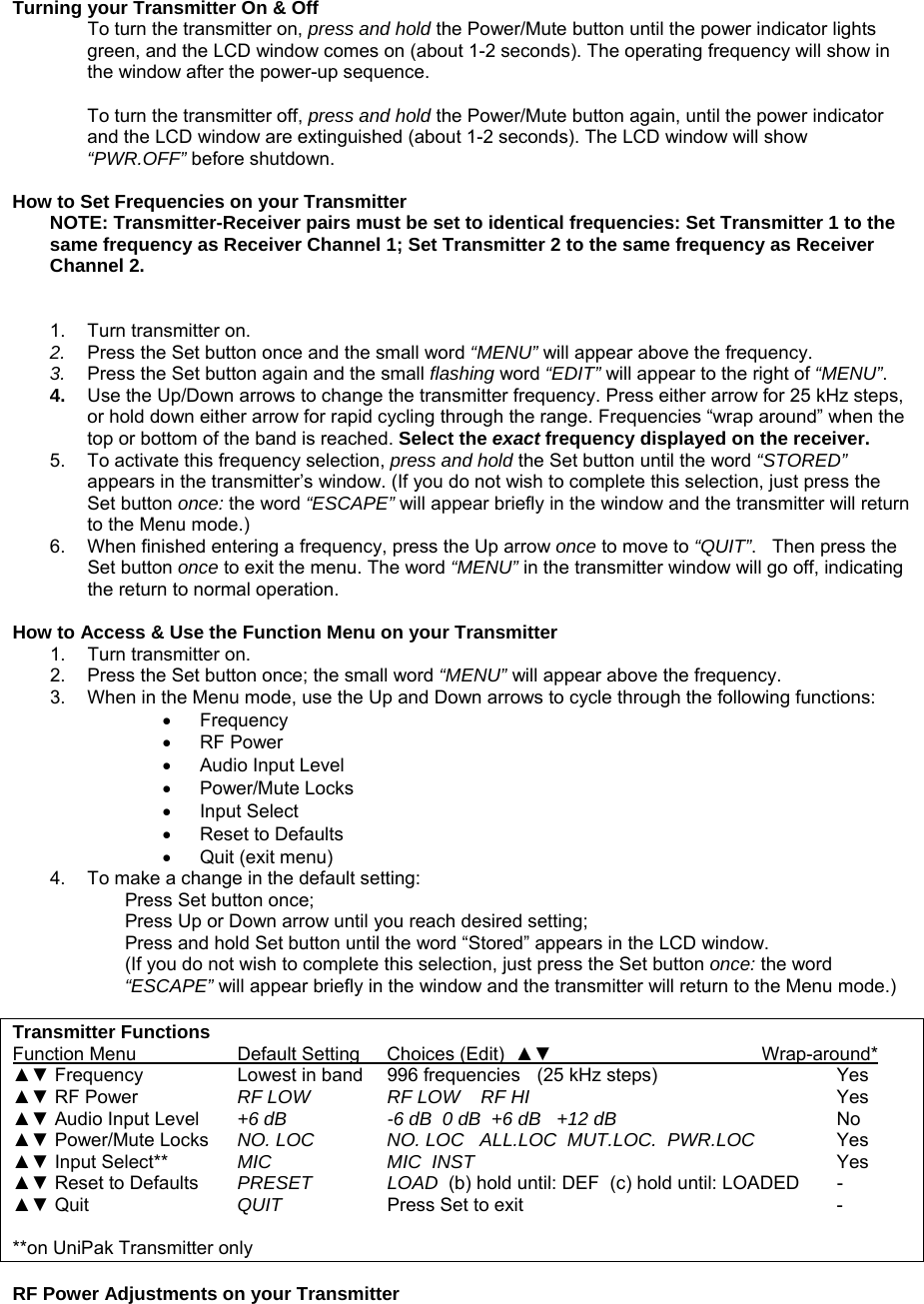
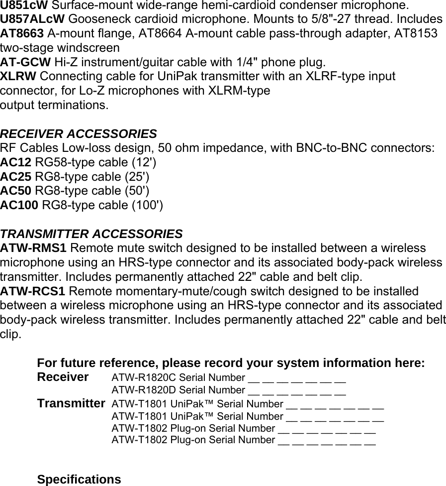
![It is also red when switch is in position 2, indicating muted operation for Receiver Channel 2. LED turns green in Hold position, indicating unit is ready for operation. Set Use with the Dual-channel Control Switch and Up/Down arrows to choose operating frequencies manually or automatically (using your choice of three automatic scan groups). Up/Down Arrows Press Up or Down arrows, in conjunction with the Set button, to choose operating frequencies manually or automatically (using your choice of three automatic scan groups). Rear Panel: Output A BALANCED AUDIO OUTPUT JACK: XLRM-type connector. Pin 1: ground (shield); Pin 2: “audio +”; Pin 3: “audio –”. A standard 2-conductor shielded cable can be used to connect the receiver output to a balanced microphone-level input on a camera, mixer or integrated amplifier. Output B BALANCED AUDIO OUTPUT JACK: XLRM-type connector. Pin 1: ground (shield); Pin 2: “audio +”; Pin 3: “audio –”. A standard 2-conductor shielded cable can be used to connect the receiver output to a balanced microphone-level input on a camera, mixer or integrated amplifier. Output Select Switch The rear panel provides two balanced XLR audio outputs (Outputs A & B). The unit is equipped with an output select switch that assigns a signal to each of the audio outputs, as follows: Output A (left) can be assigned either Receiver Channel 1 or MIX. (MIX = Ch. 1 and Ch. 2 signals mixed together. The relative levels of each signal can be adjusted using the individual receiver level controls.) Output B (right) can be assigned either Receiver Channel 1, Receiver Channel 2, or Mix. Typical configuration: Output A is assigned Channel 1; Output B is assigned Channel 2, feeding individual channels in a mixer or camera. Many other options are available, providing much flexibility, for instance: • If your camera doesn’t accept two inputs, you can sum the signal from both transmitters in Output A and connect this mixed signal to your camera. • You can connect Output A (mixed signal) to a camera, and Output B (mixed signal) to an audio mixer • When using the unit with a single transmitter (single-channel operation), Output A can be used to feed a camera, while Output B can feed an audio mixer (both with identical signals from Receiver Channel 1). Receiver Level Controls [1and 2] The signal levels of each receiver signal (Receiver Channel 1 and Receiver Channel 2) may be adjusted using these controls. When the outputs are assigned to a single receiver signal, these controls will adjust the output level. (Turn clockwise to increase output level.) When the outputs are assigned to MIX, these controls adjust the relative levels between the receiver signals. Monitor Select Switch This switch assigns a signal to the Monitor headphone output. • Choose 1 [left position] to hear Channel 1 in both ears (mono signal, stereo output); • Choose 2 [right position] to hear Channel 2 in both ears (mono signal, stereo output);](https://usermanual.wiki/Audio-Technica/T1801D/User-Guide-715926-Page-5.png)
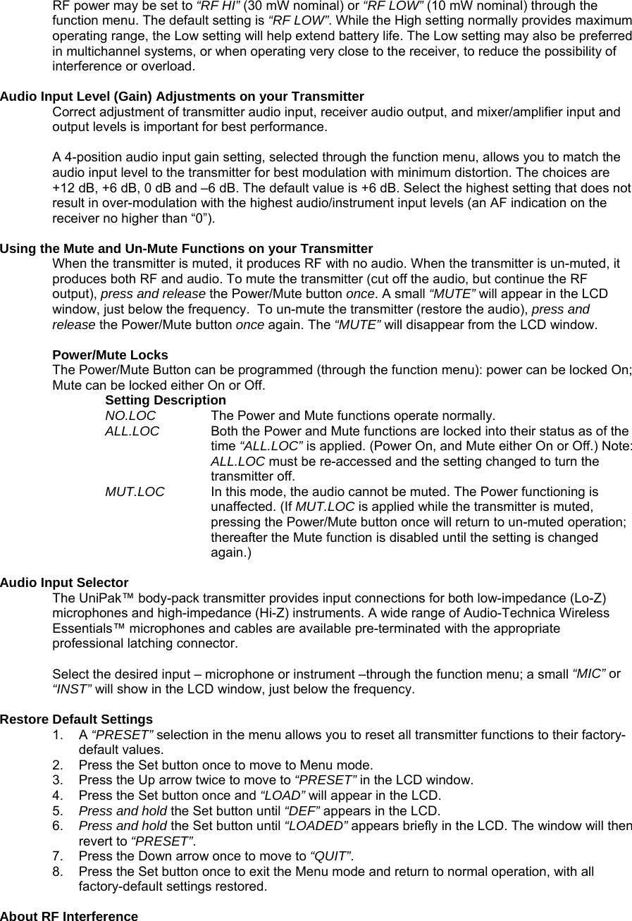
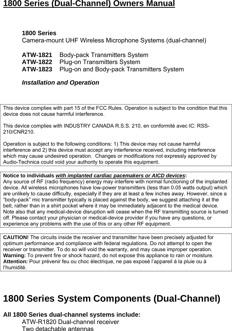
![• Choose Out [middle position], to hear Output A in the left ear, and Output B in the right ear. Monitor Level Control The level control (volume control) for headphones is independent of other level controls. Turn to the right to increase output (turn up the volume). DC Input You may connect the unit to an external power supply (12V DC source, 500 mA nominal current, not included. In this case, move the Power Switch to the “External” position; both receiver channels are activated (indicated by illumination of power/peak LEDs 1 and 2). Monitor Output ¼” TRS jack. Side Access: Battery Selection Each ATW-R1820 dual-channel receiver uses six 1.5V AA batteries, not included. Alkaline type is recommended. Always replace all batteries. Make certain the receiver power is Off before replacing batteries. Note: The ATW-R1820 receiver also functions without batteries if connected to an external power supply (12V DC source, 500 mA nominal current, not included). Receiver Battery Installation 1. Open the battery compartment door by pushing the catch back 2. Observe correct polarity as marked and carefully insert six fresh 1.5V AA alkaline batteries 3. Replace the door, making certain the latch clicks securely in place. Battery Condition Indicator After the batteries are installed, turn the power on by moving the Power switch to either the 1 or Both position. The small red power-on LED should light (red light at 1 if Power switch is in position 1; right light at 1 & 2 if Power switch is in Both position) and the LCD window should come on. If this does not happen, the batteries are installed incorrectly or they are dead. The receiver’s “fuel gauge” battery indicator displays a maximum of four bar segments. When LCD flashes LOW.BAT, the batteries should be replaced immediately to ensure continued operation. Operating the Receiver NOTE: Receiver Channel 1 and Receiver Channel 2 must be set to different frequencies to avoid interference. Transmitter-Receiver pairs must be set to identical frequencies: Set Transmitter 1 to the same frequency as Receiver Channel 1; Set Transmitter 2 to the same frequency as Receiver Channel 2. Selecting Frequencies on your Dual-channel Receiver Overview… 1. Turn the power on by moving the Power switch to either the 1 position (for single-channel operation) or Both position (for dual-channel operation). 2. Switch the Dual-channel Control Switch to 1 (to set frequency for Receiver Channel 1) or 2 (to set frequency for Receiver Channel 2). Audio output is muted for the channel that is selected. 3. Press the Set button to enter the Frequency Selection Menu mode; the world “Menu” will appear.](https://usermanual.wiki/Audio-Technica/T1801D/User-Guide-715926-Page-6.png)