Audio Technica T220AD HANDHELD WIRELESS MICROPHONE User Manual
Audio-Technica Corporation HANDHELD WIRELESS MICROPHONE Users Manual
Users Manual
2000 Series
Frequency-agile True Diversity UHF Wireless System
Installation and Operation

2000 Series Installation and Operation
2
This device complies with part 15 of the FCC Rules. Operation is
subject to the condition that this device does not cause harmful
interference.
This device complies with INDUSTRY CANADA R.S.S. 210, en
conformité avec IC: RSS-210/CNR210. Operation is subject to the
following conditions: 1) This device may not cause harmful interference
and 2) this device must accept any interference received, including
interference which may cause undesired operation.
CAUTION! Electrical shock can result from removal of the receiver
cover. Refer servicing to qualied service personnel. No user-
serviceable parts inside.
• To prevent re or shock hazard, do not expose this appliance to rain
or moisture.
• To prevent re, do not place any naked ame sources (such as
lighted candles) on the apparatus.
• To prevent re, do not cover the ventilation of the apparatus with
newspaper, tablecloths, curtains etc.
• Do not expose this apparatus to drips or splashes.
• Do not place any objects lled with liquids, such as vases, on the
apparatus.
• Do not install this apparatus in a conned space such as a bookcase
or similar unit.
• The apparatus should be located close enough to the AC outlet
so that you can easily grasp the AC adapter at any time. In case of
emergency, disconnect the AC adapter quickly.
• Danger of explosion if battery is incorrectly replaced. Replace only
with the same or equivalent type.
• Always consider environmental issues and follow your local
regulations when disposing of batteries. Do not expose batteries
to excessive heat.
The circuits inside the receiver and transmitter have been precisely
adjusted for optimum performance and compliance with federal
regulations. Do not attempt to open the receiver or transmitter.
To do so will void the warranty, and may cause improper operation.
Notice to individuals with implanted cardiac pacemakers
or AICD devices:
Any source of RF (radio frequency) energy may interfere with normal
functioning of the implanted device. All wireless microphones have
low-power transmitters (less than 0.05 watts output) which are unlikely
to cause difculty, especially if they are at least a few inches away.
However, since a “body-pack” mic transmitter typically is placed against
the body, we suggest attaching it at the belt, rather than in a shirt
pocket where it may be immediately adjacent to the medical device.
Note also that any medical-device disruption will cease when the RF
transmitting source is turned off. Please contact your physician or
medical-device provider if you have any questions, or experience any
problems with the use of this or any other RF equipment.
RF Interference
Please note that wireless frequencies are shared with other radio
services. According to Federal Communications Commission
regulations, “Wireless microphone operations are unprotected
from interference from other licensed operations in the band. If any
interference is received by any Government or non Government
operation, the wireless microphone must cease operation...” If you
need assistance with operation or frequency selection, please contact
your dealer or Audio-Technica. Extensive wireless information also is
available at www.audio-technica.com.
Thank you for choosing an Audio-Technica professional wireless
system. You have joined thousands of other satised customers who
have chosen our products because of their quality, performance and
reliability. This Audio-Technica wireless microphone system is the
successful result of years of design and manufacturing experience.
Each 2000 Series wireless system provides a choice of 10 PLL
synthesized UHF frequencies in one of ve UHF frequency ranges,
available for exible performance in a wide variety of regions
worldwide:
Frequency Range
Band D 656.125 – 678.500 MHz
Band E 800.550 – 813.150 MHz
Band F 854.900 – 864.900 MHz
Band G 722.125 – 744.500 MHz
Band I 487.125 – 506.500 MHz
The band letter reference at the end of 2000 Series Stock Numbers
indicates what band system/component operates in. For simplicity,
model numbers used throughout this manual will reference only the
basic model number without the band indications.
Each wireless system includes a receiver and either a body-pack or
handheld transmitter. UniPak® body-pack transmitter systems include
accessory microphones for particular applications. All A-T Wireless
Essentials® microphones and cables, available separately, are pre-
terminated for use with any Audio-Technica 2000 Series wireless
system.
The ATW-R2100a receiver features true diversity reception. Two
antennas feed two completely independent RF sections on the same
frequency; automatic logic circuitry continuously compares and
selects the superior received signal, providing better sound quality and
reducing the possibility of interference and dropouts. The receiver also
offers a switchable output attenuator to reduce the level of the output
signal by 12 dB for exible use with a variety of system congurations.
Switchable antenna power is also provided. Soft-touch controls provide
convenient access to selection of operating frequency and automatic
scanning, while an LCD information display provides constant
monitoring of system operation. The receiver is half-width for a standard
1U 19" rack mount; rack-mount adapters are included. Two receivers can
be mounted side by side, using an optional AT8630 joining-plate kit.
The versatile ATW-T210a UniPak® body-pack transmitter has both
low- and high-impedance inputs plus a bias connection, for use
with dynamic and electret condenser microphones, as well as Hi-Z
instrument pickups. The UniPak® transmitter also offers separate trim
controls for instrument and microphone, plus switchable high/low RF
power.
The ATW-T220a handheld dynamic microphone/transmitter features
the same element used in the PRO 41 dynamic handheld microphone
created for professional live-sound venues. It also offers switchable
high/low RF power. Both the ATW-T210a UniPak® and ATW-T220a
handheld transmitters also offer charging contacts so the units can be
placed in an optional recharging station for multi-transmitter charging.
For economical operation and wide availability, transmitters in the
2000 Series use two 1.5V AA alkaline batteries or rechargeable two AA
NiMH batteries for use with Audio-Technica’s ATW-CHG2 Recharging
Station. Both transmitters have battery condition indicators. 2000 Series
receivers feature a sophisticated Tone Lock™ tone squelch system that
opens the receiver’s audio output only when a 2000 Series transmitter
is detected, reducing the possibility of interference. As a result, 2000
Such modifications could void the user's
authority to operate the equipment.
2000 Series Installation and Operation
3
Series transmitters and receivers must be used together and should not
be used with components from other Audio-Technica wireless systems,
or with those of other manufacturers.
Please note that in multiple-system applications there must be a
transmitter-receiver combination set to a separate channel (frequency)
for each input desired (only one transmitter for each receiver).
Because the wireless frequencies are within UHF TV frequency bands,
only certain channels (operating frequencies) may be useable in a
particular geographic area. The 10 channels (operating frequencies) per
band that are used in the 2000 Series have been selected for multi-
channel compatibility. Subject to frequency availability in a particular
geographic area, any of these 10 channels may be used together. The
operating frequencies that correspond to each of the 10 channels are
listed on page 10.
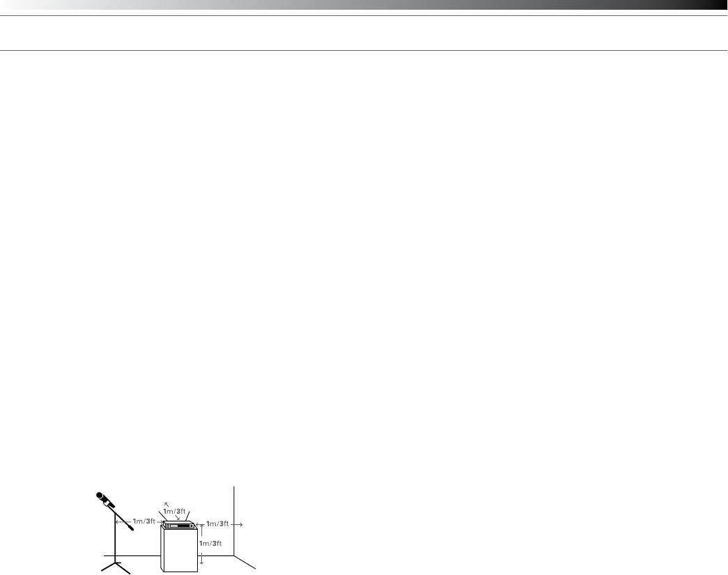
Receiver Installation
Location
For best operation the receiver should be at least 3 ft. (1 m) above the
ground and at least 3 ft. away from a wall or metal surface to minimize
reections. The transmitter should be at least 3 ft. from the receiver,
as shown in Figure A. Keep antennas away from noise sources such
as digital equipment, motors, automobiles and neon lights, as well as
away from large metal objects.
Fig. A
Output Connections
There are two audio outputs on the back panel: balanced and
unbalanced. Use shielded audio cable for the connection between the
receiver and the mixer. If the input of the mixer is a 1/4" jack, connect a
cable from the 1/4" unbalanced audio output on the back of the receiver
housing to the mixer. If the input of the mixer is an XLR-type input,
connect a cable from the balanced XLR-type audio output on the back
panel to the mixer. The two isolated audio outputs permit simultaneous
feeds to both unbalanced and balanced inputs. For example, both a
guitar amp and a mixer can be driven by the receiver.
Antennas
Attach the included pair of UHF antennas to the antenna input jacks.
The antennas are normally positioned in the shape of a “V” (both 45°
from vertical) for best reception.
Accessory antennas can be remotely located from the receiver.
However, due to signal loss in cables at UHF frequencies, use the
lowest-loss RF cables practical for any cable runs over 25 feet. RG8-
type is a good choice. Use only copper-shielded cable, not CATV-type
foil-shielded wire. Audio-Technica offers quality RF cables in four
lengths, as well as remote antennas; see audio-technica.com for a wide
selection of wireless system accessories.
Antenna Power
The antenna input jacks also can provide +12V DC output on their
center pins to power inline RF devices. A maximum of 60 mA can be
drawn from each of the jacks. While an accidental short-circuit will not
harm the internal 12V supply, make certain that an antenna cable shield
does not contact the center conductor. Antenna Power is selected by
a switch on the back of the ATW-R2100a Receiver. The unit is shipped
with the switch in the “off” position.
Note: the antennas included with the ATW-R2100a Receiver do not
require power. If you have an antenna system that requires power
(such as powered antennas or active combiners or splitters) switch the
Antenna Power switch to the “on” position.
Power Connections
Connect the included AC adapter to the DC power input on the back of
the receiver. Loop the small cord from the DC plug over the cord hook
above the jack, to keep the plug from being detached by an accidental
tug on the cord. Operation of the receiver is controlled by the front-
panel Power switch.
2000 Series Installation and Operation
4
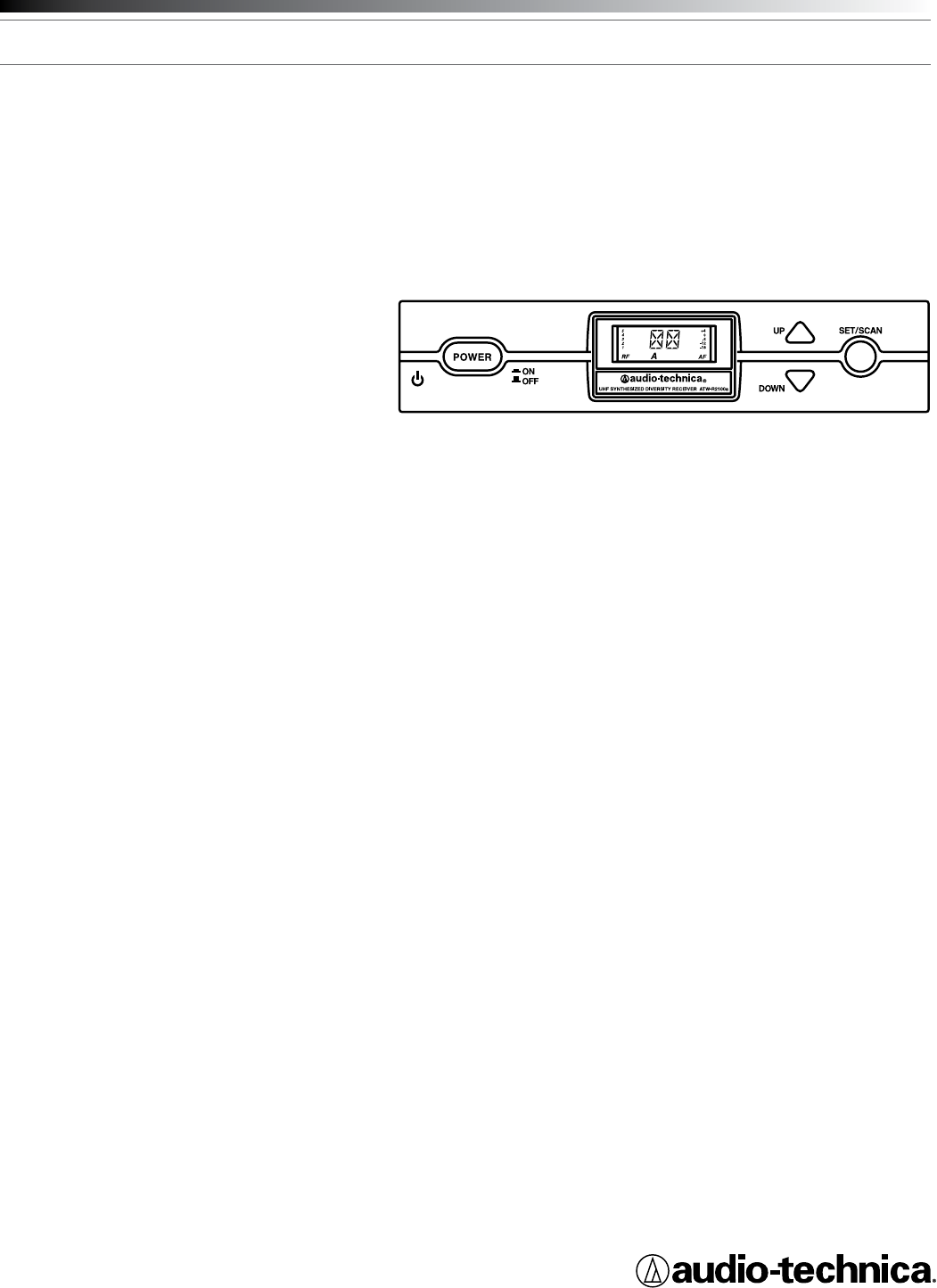
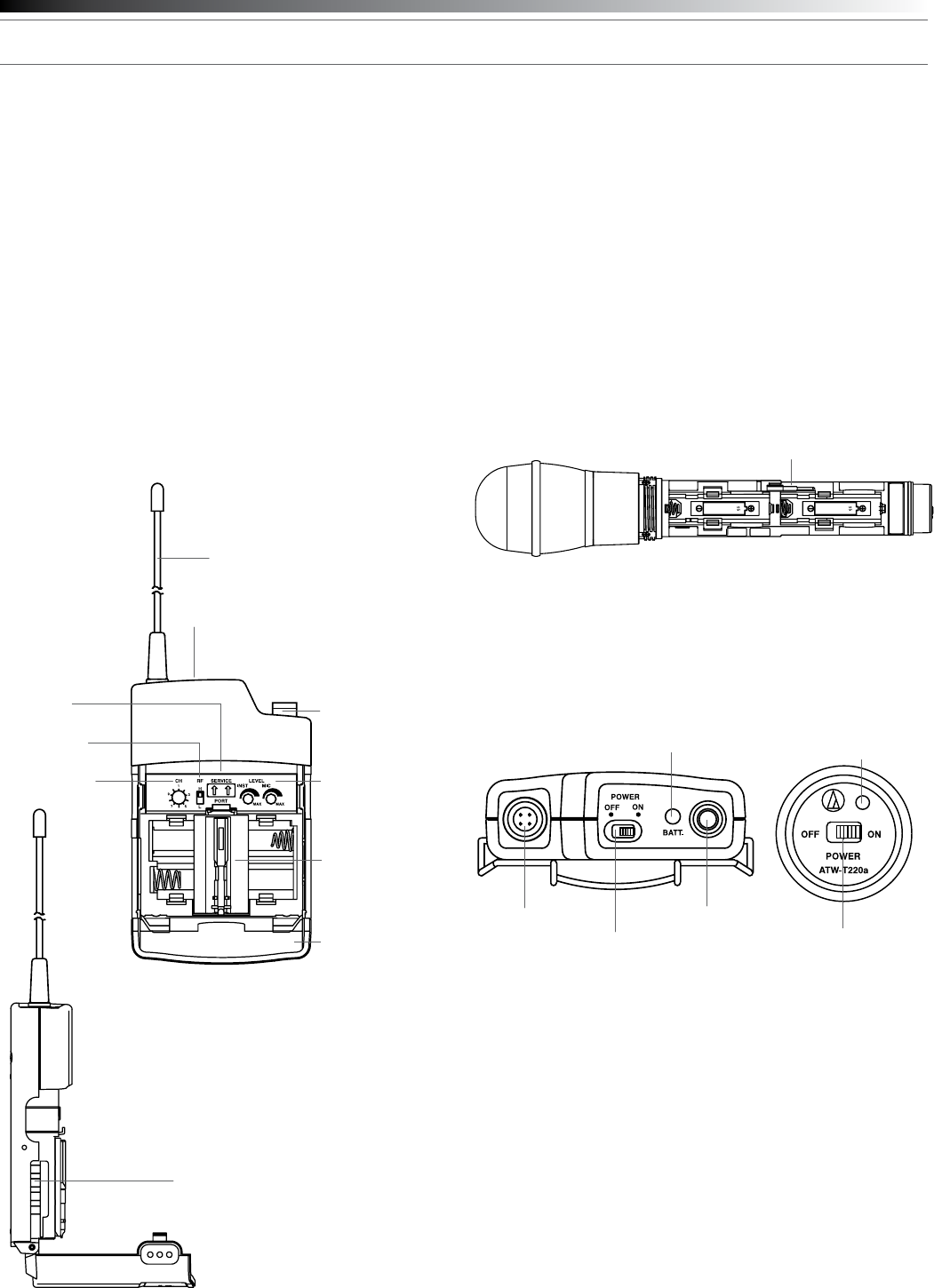
Receiver Controls and Functions
Fig. B – Front Panel Controls and Functions
1. POWER SWITCH: Press the Power switch in to turn the receiver
on. The LCD window will light, and the operating channel number
will be displayed in the window. To turn the receiver off, press the
Power switch again.
2. LCD WINDOW: Liquid Crystal Display indicates channel setting and
operational readings. See Fig. C for examples.
3. UP/DOWN BUTTONS: Press Up or Down arrow buttons to arrive at
desired channel. The selected number will ash on and off. Press
and hold Set/Scan button to set the channel (operating frequency).
4. SET/SCAN BUTTON: Two distinct operations are associated with
this button:
Touch: A momentary press of the Set/Scan button.
Hold: A press and hold (about two seconds) of the Set/Scan button.
The Set/Scan button can be used in two ways: Manual Set Mode,
to permit selection of an operating channel; and Automatic Scan/Set
Mode, to initiate the automatic channel scan and selection, as follows:
Manual Set Mode: After using the Up or Down arrow button to
arrive at desired channel, hold the Set/Scan button to set the
channel. NOTE: Before the channel has been set, a touch of the
Set/Scan button will revert the channel to its previous setting.
Automatic Scan/Set Mode: Hold the Set/Scan button. The Automatic
Scan/Set Mode will automatically scan for and set the next open
channel.
5. MOUNTING ADAPTERS: For mounting the receiver in any standard
19" rack. Attach adapters to the receiver with the screws supplied
and remove the four receiver feet. (Use optional AT8630 joining-
plate kit to mount two ATW-R2100 receivers side-by-side.)
Fig. C – Receiver LCD Window Display
6. RF SIGNAL LEVEL INDICATOR: Shows the strength of the RF signal
received from the transmitter.
7. TUNER OPERATION INDICATOR: Indicates which Tuner (A or B) has
the better reception and is in operation.
8. CHANNEL DISPLAY: Shows which channel is selected.
9. AF LEVEL INDICATOR: Shows the audio modulation level of the
received signal.
1 2 3 4 5
6 7 98
2000 Series Installation and Operation
5
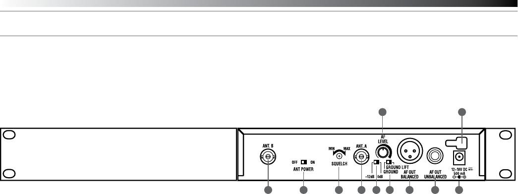
Fig. D – Rear Panel Controls and Functions
10. ANTENNA INPUT JACK: BNC-type antenna connector for
Tuner “B.” Attach the antenna directly, or extend it with a low-loss
antenna cable. See the “Antennas” section on page 3 for more
details.
11. ANTENNA POWER SWITCH: Two-position switch turns on/off the
12V AC antenna power for use with powered antennas or
accessories. Factory setting is off. See the “Antennas” section on
page 3 for more details.
12. SQUELCH CONTROL: Adjusts level of noise-muting circuit (preset
at factory but can be adjusted as circumstances warrant). Factory
setting is full counterclockwise (minimum).
13. ANTENNA INPUT JACK: Input for Tuner “A.” Attach the supplied
antenna directly, or extend it to an accessory antenna with a low-
loss antenna cable.
14. AF OUTPUT ATTENUATOR: Two-position switch adjusts audio output
level of the balanced (XLR) audio output jack with attenuation of
0 dB or –12 dB. Factory setting is 0 dB.
15. AF LEVEL CONTROL: Adjusts audio output level of both AF output
jacks. Factory setting maximum output—fully clockwise.
16. GROUND LIFT SWITCH: Disconnects the ground pin of the
balanced output jack (15) from ground. Normally, the switch should
be to the left (ground connected). If hum caused by a ground loop
occurs, slide switch to the right (ground lifted). Factory setting is
ground connected.
17. BALANCED AUDIO OUTPUT JACK: XLRM-type connector. A
standard 2-conductor shielded cable can be used to connect the
receiver output to a balanced microphone-level input on a mixer or
integrated amplier.
18. UNBALANCED AUDIO OUTPUT JACK: 1/4" phone jack. Can be
connected to an unbalanced aux-level input of a mixer, guitar amp or
tape recorder.
19. POWER INPUT JACK: Connect the DC plug from the included in-line
AC adapter.
20. CORD HOOK: Loop the small DC cord around the cord hook to keep
the DC plug from pulling out accidentally.
10 11 13 1412 1716 18 19
15 20
2000 Series Installation and Operation
6
Transmitter Controls and Functions
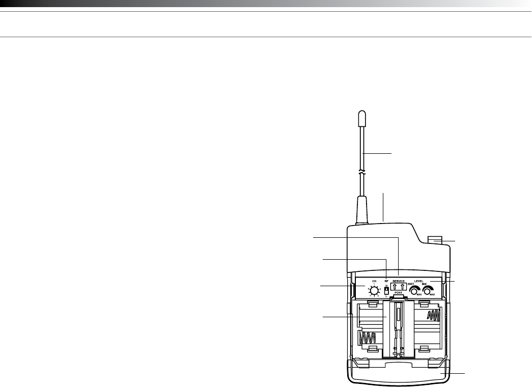
Battery Selection
Two 1.5V AA alkaline batteries or rechargeable AA NiMH batteries
for use with Audio-Technica’s ATW-CHG2 Recharging Station are
recommended.
UniPak®
Transmitter Battery Installation
1. Open the transmitter door by pressing gently on the side-cover
indentations and pulling back the hinged cover.
2. Lift the battery-keeper arm, and carefully insert two fresh 1.5V AA
alkaline batteries or rechargeable AA NiMH batteries, observing
correct polarity as marked inside the battery compartment.
3. Close the battery-keeper arm.
4. Close the transmitter door.
Fig. E – UniPak® Transmitter Open
Handheld Transmitter Battery Installation
1. While holding the upper part of the transmitter body below the ball-
screen, unscrew the lower body cover, slide it downward, and
remove it to expose the battery compartment.
2. Observe correct polarity as marked inside the battery compartment
and carefully insert two fresh 1.5V AA alkaline batteries or
rechargeable AA NiMH batteries. Make certain the batteries are fully
seated in the battery compartment. (Fig. F )
3. Slide the lower body cover back up the body, then screw the
housing together. Do not overtighten.
Note: Remove batteries from the handheld transmitter starting at the
bottom end, where nger indents in the battery housing are provided
for easy grip.
Fig. F – Handheld Transmitter Battery Compartment
Battery Indicator
After the battery is installed, turn on the power switch (located on
the bottom of the handheld transmitter and on the top of the UniPak
transmitter). The battery indicator LED (Fig. G/H) should turn red. If it
does not, the batteries are installed incorrectly or they are dead.
Fig. G – UniPak Transmitter
Top View
UniPak®Transmitter Input Connection
Connect an audio input device (microphone or guitar cable) to the
audio input connector on the top of the transmitter. A number of
Audio-Technica professional microphones and cables are available
separately, pre-terminated with a UniPak input connector.
UniPak® Transmitter Antenna
The ATW-T210a UHF UniPak® body-pack transmitter includes one
eld-replaceable antenna mounted on the transmitter. The antenna
simply screws into the transmitter’s antenna tting. Check the installed
antenna occasionally to make certain it is snugly attached (only nger-
tight). If the received signal is marginal, experiment with different
transmitter positions on your body or instrument or try repositioning the
receiver. Do not attempt to modify the transmitting antenna. Replace
it only with the same parts, available from the Audio-Technica Service
Department.
Charging Contacts
Transmitter
Door
Antenna
Audio Input Jack
Instrument/
Microphone Level Trim
Controls
Channel Selector
Switch
RF Power
Select Switch
Service Port
(for factory use only)
Battery-keeper
Arm with
Screwdriver
attached
Power-on LED
Screwdriver
Input Connector
Power Switch
Battery Indicator
Antenna
Power Switch
Battery Indicator
Fig. H – Handheld Transmitter
Bottom View
2000 Series Installation and Operation
7
System Operation
Switch on the receiver. Do not switch on the transmitter yet.
Receiver On…
The LCD display will light up and one of the tuner operation indicator
LCD segments (A or B) will light, even though the transmitter is not on.
If two or more of the RF LCD segments light up at this point, there may
be RF interference in the area. If this occurs, change operating channels
(select another frequency).
How to Make Operating Channel Changes
Operating channel changes (frequency changes) may be made in two
ways: manually and automatically.
To change channel manually
1. Use the Up/Down arrow buttons to reach the desired channel
number.
2. Hold the Set/Scan button until the channel number stops ashing
to set the receiver to the channel indicated. NOTE: Before the
channel has been set, a touch (momentary press) of the Set/Scan
(rather than a hold) will revert the channel to its previous setting.
To change channel automatically
1. Hold the Set/Scan button. The Automatic Scan/Set Mode will
automatically scan for and set the next open channel. LCD screen
will ash “FS” four times to indicate start of scan.
Transmitter On…
Before turning on the transmitter, use the provided screwdriver to
set the transmitter channel selector switches (Fig. E/I) to the same
numbers as those displayed on the receiver. Always turn the transmitter
off when changing channels (frequencies).
The transmitters have a two-position, on-off power switch. When the
switch is “On,” the transmitter produces both RF and audio.
The transmitters have a two-position RF power select switch, offering
low/high transmission modes to conserve battery life/maximize power.
Factory setting is high.
There is about a half-second delay after the transmitter is switched to
the “On” position before the receiver’s Tone Lock squelch un-mutes the
receiver.
When the transmitter is switched on and in normal operation, the
receiver’s RF signal level indicators will display as dark segments (signal
strength indicators) from bottom to top at the left side of the LCD
display.
Setting Levels
Correct adjustment of transmitter audio input, receiver audio output,
and mixer/amplier input and output levels is important for optimum
system performance.
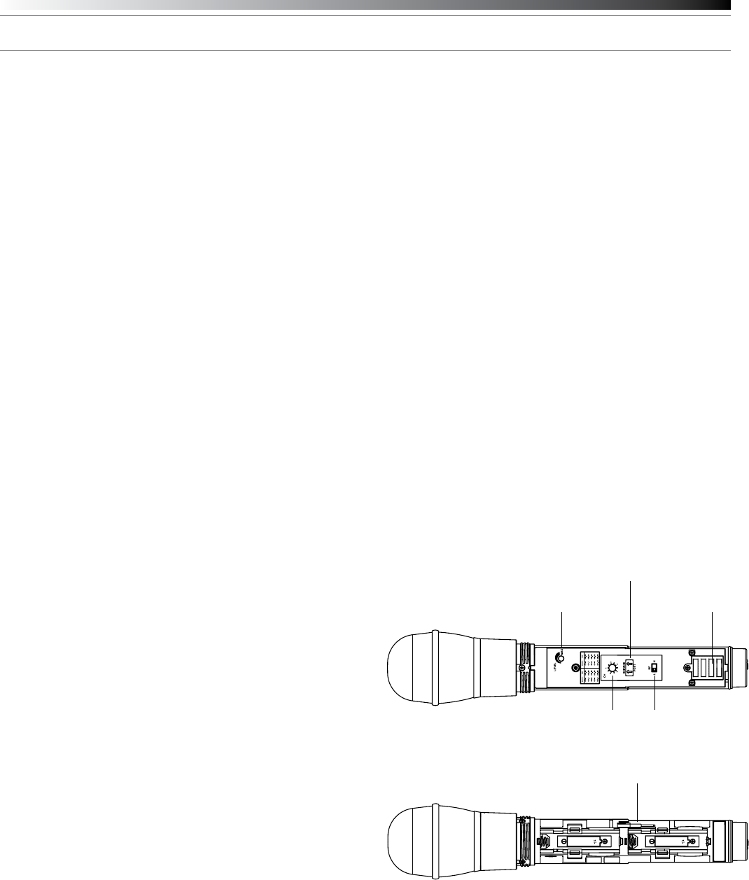
ATW-T220a Handheld Transmitter
The 2000 Series handheld transmitter has factory pre-set audio input
levels. Factory setting is full clockwise, maximum gain.
1. While speaking/singing into the microphone at typically loud levels,
check the AF meter levels on the receiver. If all ve AF meter bars
are consistently illuminated and distortion is heard through the
system, it may be necessary to adjust the transmitter audio input
level.
2. To adjust the transmitter audio input level, unscrew the lower body
cover and slide it downwards, exposing the screwdriver and level
trim control (Fig. I ). Remove the screwdriver and gently turn the level
trim control counterclockwise until the topmost receiver AF level
meter bar is illuminated only on audio peaks.
3. Return the screwdriver to its clip and close and secure the lower
body. No further transmitter gain adjustments should be needed, as
long as the acoustic input does not change signicantly.
CAUTION! The small trimmer controls are delicate; use only the
supplied screwdriver. Do not force the trimmers beyond their normal
180° range of rotation. Return the screwdriver to its storage clip when
not in use.
Fig. I – Handheld Transmitter Interior View
Charging Contacts
RF Power
Select Switch
Service Port
(for factory use only)
Channel
Selector
Switch
Level Trim Control
Screwdriver
2000 Series Installation and Operation
8
Setting Levels (Continued)
ATW-T210a UniPak® Transmitter
Trimmer adjustments in the UniPak® transmitter (Fig. E) will enable you
to use microphones or instruments with different output levels.
1. For MIC: Set microphone level trim control fully clockwise
(maximum) and instrument level trim control fully counterclockwise
(minimum). Factory setting is fully clockwise (maximum).
For INSTRUMENT: Set instrument level trim control fully clockwise
(maximum) and microphone level trim control fully counterclockwise
(minimum). Factory setting is fully clockwise (maximum).
2. Set the receiver’s AF Level control to its full clockwise position
(maximum). See Figure D on page 5.
3. Plug the mic or instrument into the transmitter and power up the
system.
4. For MIC: Make an initial adjustment of the mixer’s level controls that
will allow audio through the system.
For INSTRUMENT: Make an initial adjustment of the instrument
amplier input level control that will allow audio through the system.
5. For MIC: While speaking/singing into the microphone at typically
loud levels, check the AF meter levels on the receiver. If all ve
meter bars are consistently illuminated and distortion is heard
through the system, it may be necessary to adjust the UniPak
transmitter audio input level. To adjust the transmitter audio input
level, gently turn the microphone level trim control counterclockwise
until the topmost receiver AF level meter bar is illuminated only on
audio peaks.
For INSTRUMENT: While playing the instrument at typically loud
levels, check the AF meter levels on the receiver. If all ve meter
bars are consistently illuminated and distortion is heard through
the system, it may be necessary to adjust the UniPak transmitter
audio input level. To adjust the transmitter audio input level, gently
turn the instrument level trim control counterclockwise until the
topmost receiver AF level meter bar is illuminated only on audio
peaks.
6. For MIC: While again speaking/singing into the microphone at
typically loud levels, adjust the mixer’s input trim control so the
highest sound pressure level going into the microphone causes no
input overload in the mixer, and yet permits the mixer’s channel and
output level controls to operate in their “normal” range (not set too
high or too low).
For INSTRUMENT: While again playing the instrument at typically
loud levels, adjust the receiver’s AF Level control so the highest
signal level causes no input overload in the instrument amplier
and yet permits the amplier’s input level controls to operate in their
“normal” range (not set too high or too low).
Note: If the mixer cannot be adjusted to operate in its normal
range without distortion, adjust the receiver’s AF Level Control (turn
counterclockwise) until the mixer/ amplier is no longer overloaded.
Fig. E – UniPak® Transmitter Open
Receiver Squelch
The squelch control on the back panel of the receiver is preset
at the factory for best system performance (factory setting is full
counterclockwise), but can be adjusted if you must use the system in
an area with considerable RF interference. If there is interference in
the audio, and changing the channel is not an option, adjust the squelch
control so the system will receive the signal from your transmitter but
will “squelch” or eliminate the unwanted background RF noise. This
adjustment can cause a reduction in useable range of the wireless
transmitter, so set the control to the lowest position that reliably mutes
the unwanted RF signals.
Transmitter
Door
Antenna
Audio Input Jack
Instrument/
Microphone Level Trim
Controls
Channel
Selector
Switch
RF Power
Select Switch
Service Port
(for factory use only)
Battery-keeper
Arm with
Screwdriver
attached
Power-on LED

2000 Series Installation and Operation
9
Specications†
Overall System
UHF Operating Frequencies
Frequency Range Number of Channels
Band D: 656.125 to 678.500 MHz 10
Band E: 800.550 to 813.150 MHz 10
Band F: 854.900 to 864.900 MHz 10
Band G: 722.125 to 744.500 MHz 10
Band I : 487.125 to 506.500 MHz 10
Not all frequencies are available in all areas. Please check with local regulations.
Modulation Mode FM
Maximum Deviation ±40 kHz
Dynamic Range > 110 dB (A-weighted), typical
Total Harmonic Distortion < 1% (at 1 kHz, ±20 kHz deviation)
Operating Range 100 m (300'), typical
Open range environment with no interfering signals.
Operating Temperature Range 5º C to +45º C
41º F to 113º F
Battery and LCD performance may be reduced at very low temperatures.
Frequency Response 100 Hz to 15 kHz (+1 dB, -3 dB)
ATW-R2100a Receiver
Receiving System True diversity
Image Rejection 60 dB nominal, 55 dB minimum
RF Sensitivity 20 dBuV at 60 dB S/N ratio
(50 ohms termination)
Maximum Output Level
XLR, balanced: +9 dBV
¼" (6.3 mm), unbalanced: +4 dBV
Balanced Audio Output Attenuator Two position switch: 0 / -12 dB
Antenna Input BNC-type, 50 ohms
Bias voltage 12V DC, 60 mA, each
Power Requirements 12-18V DC, 500 mA
Dimensions 210.0 mm (8.27") W x
162.2 mm (6.39") D x
44.0 mm (1.73") H
Not including BNC connectors or feet.
Net Weight 1.0 kg (35.3 oz), without accessories
Accessories Included Two exible UHF antennas;
AC adapter (country dependent);
rack-mount adapters
ATW-T210a UniPak® Transmitter
RF Power Output (50 ohms) High: 30 mW, Low: 10 mW
(switchable)
Spurious Emissions Following federal and national
regulations
Input Connection Four-pin Locking Connector
Pin 1: GND, Pin 2: INST INPUT,
Pin 3: MIC INPUT, Pin 4: DC BIAS +9V
Batteries Two 1.5V AA, not included
Battery Life High: 7 hours (alkaline)
Low: 9 hours (alkaline)
Depending on battery type and use pattern.
Dimensions 66.0 mm (2.60") W x
22.5 mm (0.89") D x
92.3 mm (3.63") H
Net Weight 81 g (2.9 oz), without batteries
ATW-T220a Handheld Transmitters
RF Power Output (50 ohms) High: 30 mW; Low: 10 mW,
(switchable)
Spurious Emissions Following federal and national
regulations
Microphone Element Dynamic cardioid
Batteries Two 1.5V AA, not included
Battery Life High: 7 hours (alkaline)
Low: 9 hours (alkaline)
Depending on battery type and use pattern.
Dimensions 232.0 mm (9.13") long,
48.0 mm (1.89") diameter
Net Weight 252 g (8.9 oz), without batteries
Accessory Included AT8456a Quiet-Flex™ stand clamp
† In the interest of standards development, A.T.U.S. offers full details on its test methods to
other industry professionals on request.
Specications are subject to change without notice.

2000 Series Installation and Operation
10
2000 Series Frequency Channel Plan
Band D
Channel Frequency-MHz
1 656 . 125
2 659 . 375
3 660 . 000
4 662 . 125
5 665 . 125
6 669 . 750
7 671 . 500
8 677 . 000
9 678 . 125
10 678 . 500
Band E
Channel Frequency-MHz
1 800 . 225
2 802 . 775
3 804 . 000
4 804 . 700
5 805 . 900
6 806 . 300
7 813 . 100
8 813 . 900
9 815 . 000
10 818 . 025
Band F
Channel Frequency-MHz
1 863 . 100
2 863 . 500
3 864 . 100
4 864 . 900
5 854 . 900
6 855 . 275
7 855 . 900
8 856 . 175
9 858 . 200
10 861 . 750
Band G
Channel Frequency-MHz
1 772 . 125
2 725 . 375
3 726 . 000
4 728 . 125
5 731 . 125
6 735 . 750
7 737 . 500
8 743 . 000
9 744 . 125
10 744 . 500
Band I
Channel Frequency-MHz
1 487 . 125
2 487 . 625
3 488 . 875
4 491 . 750
5 494 . 375
6 495 . 375
7 501 . 375
8 503 . 375
9 505 . 750
10 506 . 500
CAUTION: U.S. Public Safety/Security Restrictions
(Private Land Mobile Radio Services)
Pertains to Band I Only.
Avoid the frequencies/channels listed below in each of the following
U.S. metropolitan areas (as of November 2009). Refer to www.fcc.gov
for updates.
Land Mobile Allocation
Metropolitan Areas 2000 Series I Band
Channels
TV Channels* to Avoid in
Indicated Metropolitan Areas
Boston, MA 1, 2 14, 16
Dallas, TX 1, 2 16
Detroit, MI 1, 2 15, 16
Houston, TX 3, 4 17
Los Angeles, CA 1, 2, 10 14, 16, 20
New York, NY 1, 2 14, 15, 16
Philadelphia, PA 7, 8, 9, 10 19, 20
Pittsburgh, PA 5, 6 14, 18
San Francisco, CA 1, 2, 3, 4 16, 17
Washington, DC 3, 4, 5, 6 17, 18
Note: Cleveland and Chicago public safety allocations (TV Channels 14 & 15) and Miami FL public
safety allocations (TV Channel 14) are outside of the 2000 Series operating bandwidth.
* The 2000 Series operates in TV channels 16-20; Channels 14 and 15 are outside the 2000 Series
operating bandwidth.
U.S. Two-Year Limited Warranty
This product and selected Audio-Technica brand products purchased in the U.S.A.
from an authorized Audio-Technica (A.T.U.S.) dealer are warranted for two years from
date of purchase by A.T.U.S. to be free of defects in materials and workmanship. To
identify those products, go to www.audio-technica.com/usawarranties. In event of a
defect, End-User’s exclusive remedy is at A.T.U.S.’ election, the cost of repair, refund
of the purchase price in the form of credit or cash, or replacement of the product.
The product must be delivered to A.T.U.S. or an Authorized Service Center, prepaid,
together with the sales slip or other proof of purchase date. This warranty excludes
defects due to normal wear, abuse, shipping damage, or failure to use product in
accordance with instructions. This warranty is void in the event of unauthorized repair
or modication, or removal or defacing of the product labeling.
For U.S. service return instructions and procedure please go to:
www.audio-technica.com/returninstructions.
A.T.U.S.’ warranty is to the End User only. Except for A.T.U.S.’ said express
warranty, A.T.U.S. MAKES NO WARRANTIES, EXPRESS OR IMPLIED, WITH
RESPECT TO THE PRODUCTS. A.T.U.S. SPECIFICALLY MAKES NO WARRANTY
OF MERCHANTABILITY OR FITNESS FOR A PARTICULAR PURPOSE.
Except to the extent precluded by applicable state law, A.T.U.S. IS NOT LIABLE
FOR CONSEQUENTIAL, INCIDENTAL, DIRECT OR SPECIAL DAMAGES ARISING,
DIRECTLY OR INDIRECTLY, IN RESPECT OF SUCH PRODUCTS OR USE OR
FAILURE THEREOF, WHETHER BASED ON BREACH OF WARRANTY, NEGLIGENCE,
STRICT LIABILITY, TORT OR OTHERWISE.
This warranty gives you specic legal rights, and you may have other rights which
vary from state to state.
Outside the U.S.A., please contact your local dealer for warranty details.
Audio-Technica U.S., Inc.
1221 Commerce Drive
Stow, Ohio 44224
11
Stetement of Compliance
Audio-Technica U.S., Inc.
1221 Commerce Drive, Stow, Ohio 44224 USA +1 (330) 686-2600
Audio-Technica Limited
Old Lane, Leeds LS11 8AG England +44 (0) 113 277 1441
Audio-Technica (Greater China) Limited
Unit K, 9/F., Kaiser Est. (Ph.2) 51 Man Yue St. Kowloon, HK. +852-2356-9268
Audio-Technica (S.E.A.) Pte. Ltd.
No 1 Ubi View, #01-14 Focus One, Singapore 408555 +65-6749-5686
Audio-Technica Corporation
2206, Naruse Machida, Tokyo Japan
©2010 Audio-Technica U.S., Inc. audio-technica.com P# 2323-04360 P52121 Printed in Malaysia
To reduce the environmental impact of a multi-language printed document, product information
is available online at www.audio-technica.com in a selection of languages.
An de réduire l’impact sur l’environnement de l’impression de plusieurs, les informations
concernant les produits sont disponibles sur le site www.audio-technica.com dans une large
sélection de langue.
Para reducir el impacto al medioambiente, y reducir la producción de documentos en varios
leguajes, información de nuestros productos están disponibles en nuestra página del Internet:
www.audio-technica.com.
Para reduzir o impacto ecológico de um documento impresso de várias linguas, a Audio-Technica
providência as informações dos seus produtos em diversas linguas na www.audio-technica.com.
Per evitare l’impatto ambientale che la stampa di questo documento determinerebbe, le
informazioni sui prodotti sono disponibili online in diverse lingue sul sito www.audio-technica.com.
Der Umwelt zuliebe nden Sie die Produktinformationen in deutscher Sprache und weiteren
Sprachen auf unserer Homepage: www.audio-technica.com.
Om de gevolgen van een gedrukte meertalige handleiding op het milieu te verkleinen, is
productinformatie in verschillende talen “on-line” beschikbaar op: www.audio-technica.com.