Audio Technica T5000AD HANDHELD WIRELESS MICROPHONE User Manual
Audio-Technica Corporation HANDHELD WIRELESS MICROPHONE Users Manual
UserManual.wiki
>
Audio Technica
>
T5000AD User Manual
Users Manual
Navigation menu
Upload a User Manual
Namespaces
Wiki Guide
HTML
PDF
Info
Views
User Manual
Discussion / Help
Navigation
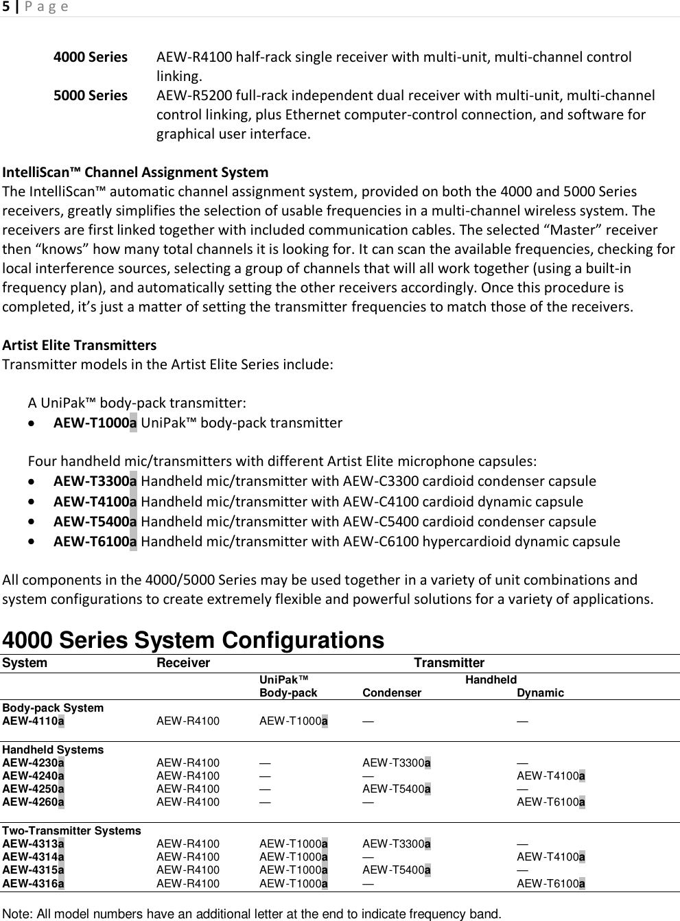
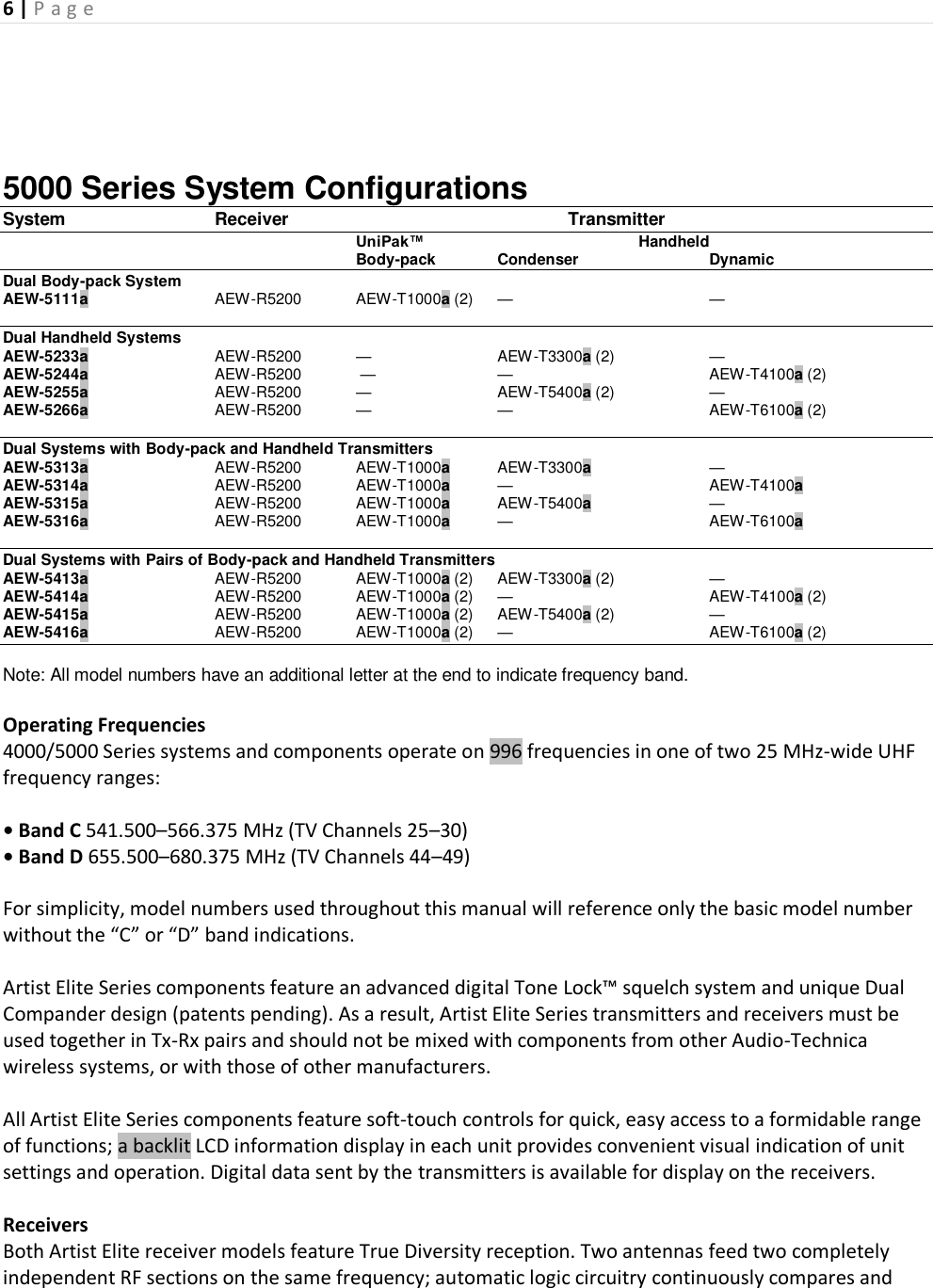
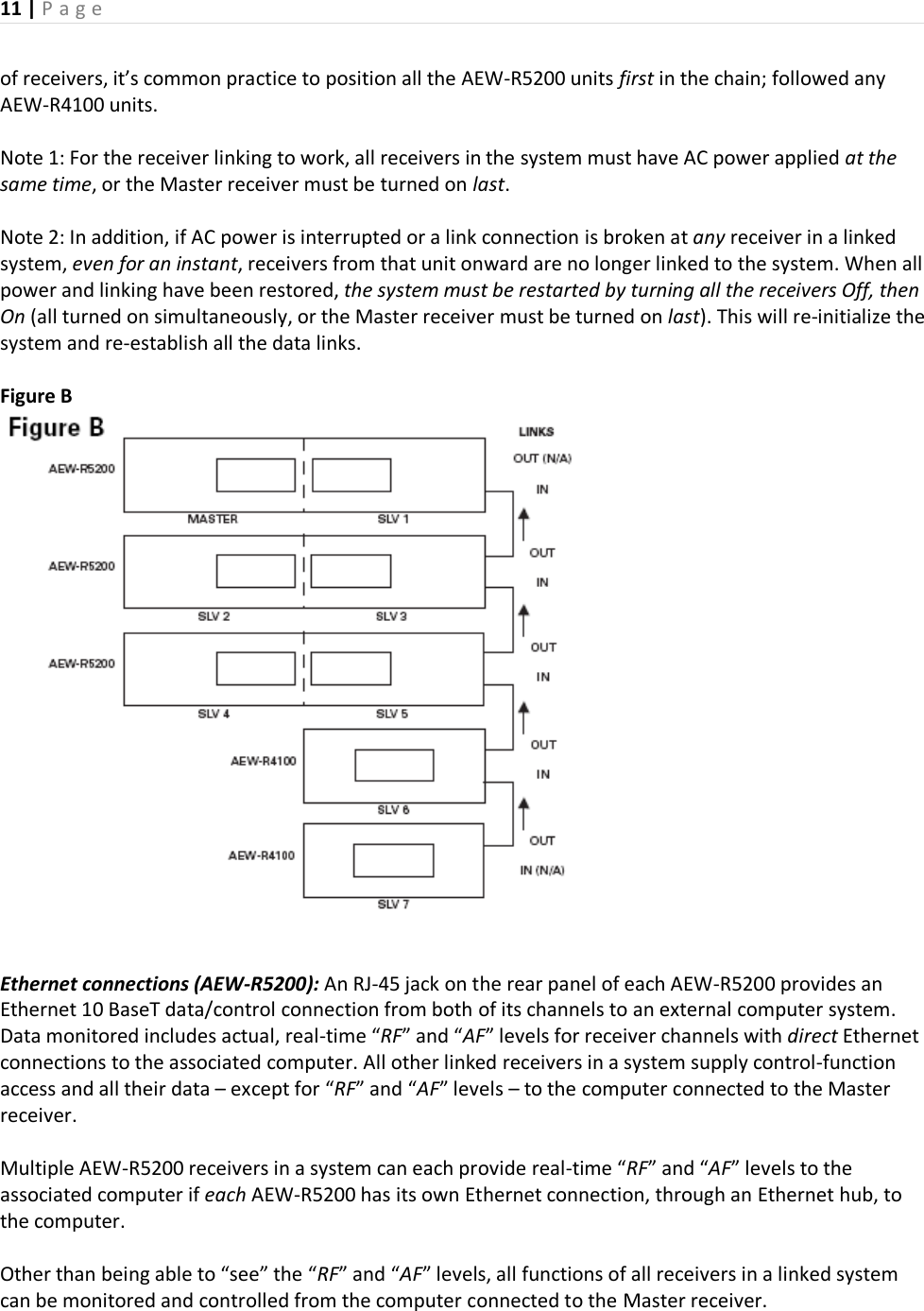
![7 | P a g e selects the superior received signal, providing better sound quality and reducing the possibility of interference and dropouts. Both receivers offer a choice of 996 operating frequencies in a 25 MHz-wide UHF frequency range. 25 khz frequency spacing enables the systems to easily find an open frequency in crowded RF environments. (For operation of two or more systems at the same time, use the IntelliScan™ function for frequency selection or, if setting the frequencies manually, use frequencies that are within the same IntelliScan groups listed on page [--].) AEW-R4100: A single synthesized UHF receiver in a half-rack 1U case. Its power supply operates on 100–240V 50/60 Hz AC power worldwide with the appropriate IEC-type power input cordset. AEW-R5200: Two independent synthesized UHF receiver channels in a full-rack 1U case. Its common power supply operates on 100–240V 50/60 Hz AC power worldwide with the appropriate IEC-type power input cordset. In addition, a “pass-through” AC outlet on each receiver with included AC jumper cable permits daisy-chaining of an entire AEW-R5200 receiver stack, freeing AC outlets for other equipment. Multi-channel Systems Artist Elite systems provide extensive monitoring and control facilities. Transmitter data, in addition to being available at the transmitter, is conveyed in digital form to and displayed on the associated receiver. Linked systems: Both Artist Elite receivers provide linking jacks and cables. AEW-R4100 and AEW-R5200 receivers may be combined in linked multi-channel systems, if desired. Ethernet-based monitoring and control (AEW-R5200): Some wireless systems on the market offer remote control/monitoring of the receiver via a serial interface, but the Audio-Technica AEW-R5200 receiver takes this a significant step further by including control over IP using standard networking protocol and Ethernet interfacing. This permits receivers in a system to be integrated, monitored and controlled from a single computer in real-time. And not only can an individual channel of an individual receiver be examined and its settings modified: if the transmitter on that channel is activated, thanks to the digital data link, data from the associated transmitter can also be monitored. Because standard control over IP is used, Ethernet-connected AEW systems can range from a single laptop controlling a free-standing multi-channel system, to local area network-based systems, to systems controlled via the Internet, even from great distances. Complete setup and operating information for computer-connected AEW systems will be found in the separate Computer Interface manual provided with AEW-R5200 receivers and 5000 Series systems. Transmitters The versatile AEW-T1000a UniPak™ body-pack transmitter features a metal case and includes field-replaceable helical and flexible-wire antennas. It has both low- and high-impedance inputs plus a bias connection, for use with dynamic and electret condenser microphones, as well as Hi-Z instrument pickups. In addition to its programmable functions, the transmitter includes a three-position sliding control cover to limit access, if desired, to only the Power/Mute button, or to no controls at all, as appropriate for the application and/or user.](https://usermanual.wiki/Audio-Technica/T5000AD/User-Guide-1249198-Page-7.png)
![8 | P a g e The handheld microphone/transmitters feature metal-body construction. Four models are available, incorporating a variety of capsules from the Artist Elite wired-microphone series created for professional live-sound venues. All Artist Elite Series transmitters use two 1.5V AA batteries for economical operation and wide availability. The receiver and both transmitters have “fuel gauge” battery condition indicators with low-battery warnings. Please note that in multiple-system applications there must be a transmitter-receiver combination set to a separate frequency for each input desired (only one transmitter for each receiver). Because the wireless frequencies are within UHF TV frequency bands, only certain operating frequencies may be usable in a particular geographic area. Also, only certain of the available operating frequencies may be used together. Operating frequencies and IntelliScan frequency groupings will be found on pages [--]. (Use of the IntelliScan channel assignment system will determine and set appropriate frequencies automatically.) Receiver Installation Receiver Installation Location For best operation the receiver should be at least 3 ft. (1 m) above the ground and at least 3 ft. away from a wall or metal surface to minimize reflections. The transmitter should be at least 3 ft. from the receiver, as shown in Figure A. Keep antennas away from noise sources such as digital equipment, motors, automobiles and neon lights, as well as away from large metal objects. Output Connections There are two audio outputs on the back panel: an XLR Mic Output and a 1/4" (6.3 mm) phone jack Instrument Output. The two isolated audio outputs permit simultaneous feeds to two different inputs. AEW-R4100: This receiver offers a balanced XLR Mic jack and an unbalanced Instrument 1/4" TS phone jack. Output levels of both are adjusted by the rear-panel Attenuator (ATTN) switch. AEW-R5200: Since there are two independent channels of receiver in the AEW-R5200, there are two sets of output jacks. All audio outputs on the AEW-R5200 are transformer-isolated and balanced. The ground connections of both outputs on each receiver channel may be interrupted (“lifted”) by use of their associated Ground Lift switch. This permits feeding mixers with different ground levels without an additional external splitter. The Instrument output is a balanced 1/4" TRS jack with “audio +” on the Tip, “audio –” on the Ring and ground (shield) on the Sleeve. The rear-panel Attenuator (ATTN) switch for each receiver channel adjusts levels of both outputs in its channel. Use the appropriate shielded audio cable for connections between the receiver and the input(s) of the mixer or other equipment. Antennas Attach a pair of UHF antennas to the antenna input jacks. The antennas are normally positioned in the shape of a “V” (both 45° from vertical) for best reception. In addition to rotating at the connector, the included half-wave antennas pivot from straight to right-angle. Antennas can be remotely located from the receiver. However, due to signal loss in cables at UHF frequencies, use the lowest-loss RF cables practical for any cable runs over 25 feet. RG8- type is a good](https://usermanual.wiki/Audio-Technica/T5000AD/User-Guide-1249198-Page-8.png)
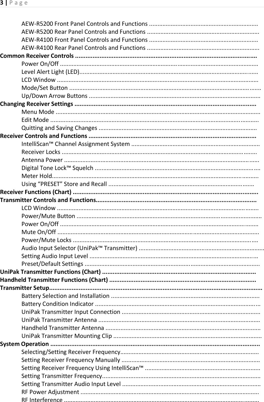
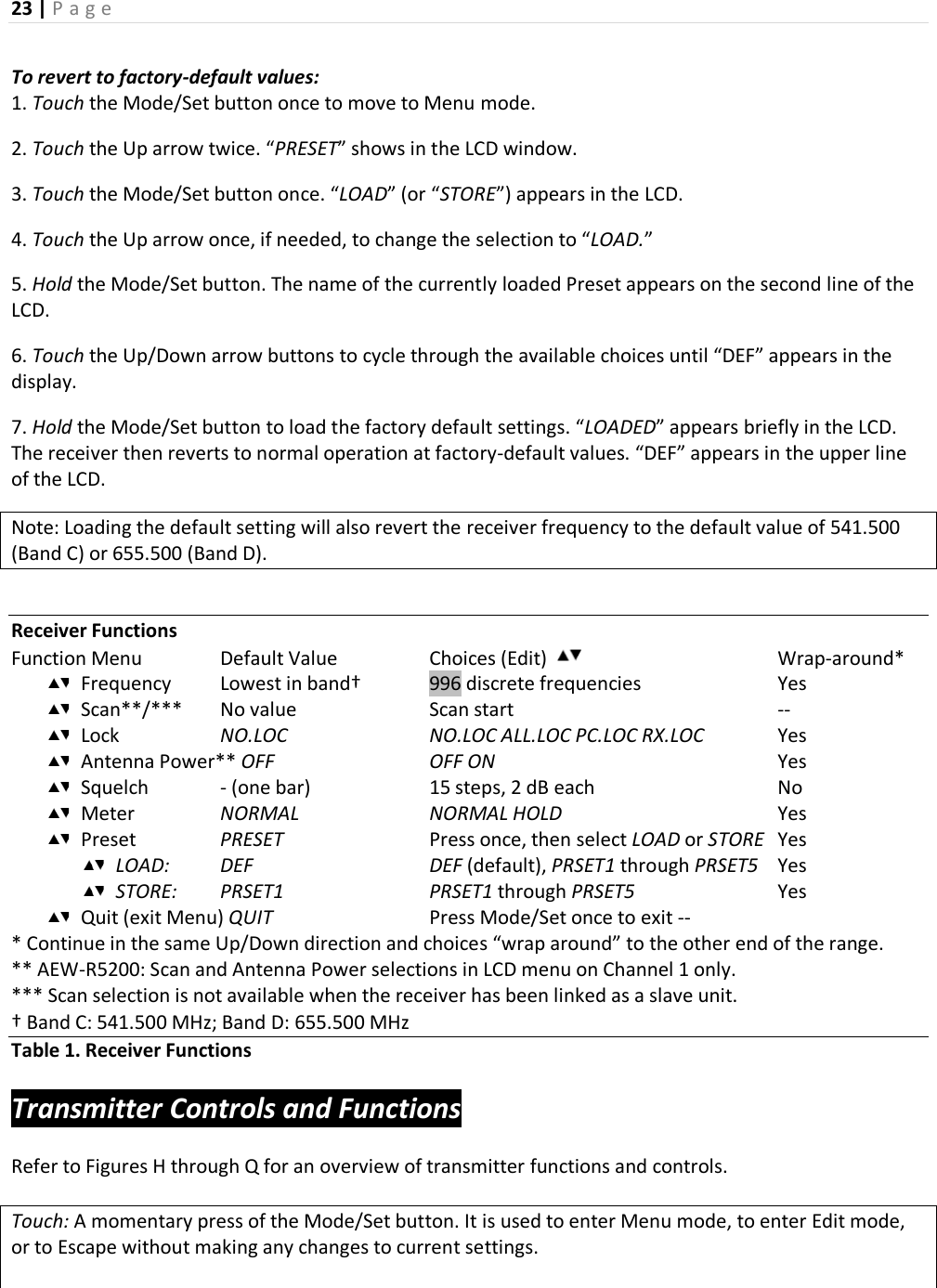
![12 | P a g e Details of the computer setup and operation will be found in a separate AEW Control Interface manual provided with AEW-R5200 receivers and 5000 Series systems. Receiver Installation (Continued) Receiver Controls and Functions Figure C AEW-R5200 Receiver Front Panel Front Panel Controls and Functions (Fig. C) 1 POWER SWITCH: Press Power switch in and the receiver readouts will light. 2 HEADPHONE OUTPUT: 1/4" (6.3 mm) TRS (“stereo”) phone jack. Plug in either a mono or "stereo" headphone to monitor receiver signal. 3 HEADPHONE LEVEL CONTROL / CHANNEL SWITCH: Adjusts the level of the headphone jack only; it does not affect receiver audio output. Press-and-release the knob to switch between Channel 1 and Channel 2. 4 HEADPHONE CHANNEL INDICATOR: Shows which receiver channel is feeding the monitor headphones. Channel 1 / Channel 2 5 / 9 ALERT INDICATOR: The Alert Indicator lights: (a) When the receiver is in the Mute mode, (b) When no RF signal is received from the transmitter, (c) When only one or two RF signal-strength bars are on, (d) When the transmitter is in the Mute mode, (e) When audio modulation level from the transmitter is close to the clipping point (AF +6 bar), or (f) When the “LOW BAT” warning appears in the LCD (transmitter battery is weak). Receiver Controls and Functions 6 / 10 LCD WINDOW: Liquid Crystal Display indicates control settings and operational readings. See Figure G on page [--] for details. 7 / 11 UP/DOWN BUTTONS: Press Up or Down arrow button, in conjunction with the Mode/Set button, to step through menus, select operating frequency and edit receiver function choices. 8 / 12 MODE/SET BUTTON: Use in conjunction with the Up/Down arrow buttons to step through menus, choose operating frequency and select receiver function options. 13 FRONT-MOUNT ANTENNAS: Cables and panel connectors are included with the AEW-R5200 to permit attaching antennas at the front panel. Figure D AEW-R5200 Receiver Rear Panel Rear Panel Controls and Functions (Fig. D)](https://usermanual.wiki/Audio-Technica/T5000AD/User-Guide-1249198-Page-12.png)
![13 | P a g e 14 ANTENNA INPUT JACK: BNC-type antenna connector for Tuner “B.” Attach the antenna directly, or extend it with a low-loss antenna cable. See the ”Antennas” section on page [--] for more details. Antenna power at +12 volts is available at both antenna jacks; select it via the LCD menu on Channel 1. 15 / 22 EXTERNAL MUTE: Permits manual and absolute muting of the receiver via a 1/4" TS phone jack and a user-provided external switch. “Shorting” the jack (closing the switch connection) mutes the receiver channel. When External Mute has been applied, the only way to un-mute the receiver is to open the External Mute switch connection. 16 / 23 INSTRUMENT OUTPUT JACK: 1/4" transformer-isolated TRS balanced phone jack output. Tip: “audio +”; Ring: “audio –”; Sleeve: ground (shield). Can be connected to an aux-level input of a mixer, guitar amp or tape recorder. Using the associated Ground Lift switch permits feeding equipment with different ground levels. 17 / 24 AF OUTPUT ATTENUATOR: Three-position switch adjusts audio output level of both audio output jacks, with attenuation of 0 dB, –6 dB or –12 dB. 18 / 25 MIC OUTPUT JACK: XLRM-type connector. Pin 1: ground (shield); Pin 2: “audio +”; Pin 3: “audio -”. A standard 2-conductor shielded cable can be used to connect the receiver output to a balanced microphone-level input on a mixer or integrated amplifier. This output is transformer-isolated from the 1/4" TRS Instrument output jack. 19 / 26 GROUND LIFT SWITCH: Disconnects the ground of both the Mic and Instrument output jacks on the associated receiver channel. Normally, the switch should be to the right (ground connected). If hum caused by a ground loop occurs, slide switch to the left (ground lifted). 20 NETWORK INTERFACE CONNECTOR: An Ethernet connection on the AEW-R5200 provides full communication and monitor/control by an associated computer. See the separate AEW Control Interface manual for computer setup and operation. 21 ANTENNA INPUT JACK: Connector for Tuner “A.” Attach the antenna directly, or extend it with a low-loss antenna cable. 27 LINK IN JACK: Connect the provided cable to this jack with the index mark on the plug aligned toward the screw head to the right of the jack. The receiver with a Link In and no Link Out connection is the “Master” unit. (With an AEW-R5200 in the Master position, its Channel 1 is the system’s Master and its Channel 2 is the first “slave.”) 28 LINK OUT JACK: Connect the provided cable to this jack with the index mark on the plug aligned toward the screw head to the right of the jack. The receiver with a Link Out and no Link In connection is the last slave in a multi-unit system.](https://usermanual.wiki/Audio-Technica/T5000AD/User-Guide-1249198-Page-13.png)
![14 | P a g e 29 AUXILIARY AC OUTLET: An auxiliary AC pass-through outlet and included “jumper” power cordset simplify making power connections to an array of AEW-R5200’s. Maximum output from the auxiliary AC outlet is 5 Amperes. 30 AC POWER INPUT: IEC-type connector for 100V–240V AC, 50/60 Hz power input. No adjustment for mains voltage/ frequency is necessary. 31 REAR RACK MOUNT: Mounts are provided at the rear of the side panels to permit attachment to rear rack rails in racks so equipped. The additional support is especially helpful when equipment is transported. Receiver Controls and Functions (Continued) Figure E AEW-R4100 Receiver Front Panel 31 14 15 16 17 18 19 20 21 22 23 24 25 26 27 28 31 Front Panel Controls and Functions (Fig. E) 32 POWER SWITCH: Press Power switch in and the receiver readouts will light. 33 HEADPHONE OUTPUT: 1/4" (6.3 mm) TRS (“stereo”) phone jack. Plug in either a mono or “stereo” headphone to monitor receiver signal. 34 HEADPHONE LEVEL CONTROL: Adjusts the level of the headphone jack only; it does not affect receiver audio output. 35 ALERT INDICATOR: The Alert Indicator lights: (a) When the receiver is in the Mute mode, (b) When no RF signal is received from the transmitter, (c) When only one or two RF signal-strength bars are on, (d) When the transmitter is in the Mute mode, (e) When audio modulation level from the transmitter is close to the clipping point (AF +6 bar), or (f) When the “LOW BAT” warning appears in the LCD (transmitter battery is weak). 36 LCD WINDOW: Liquid Crystal Display indicates control settings and operational readings. See Figure G on page [--] for details. 37 UP/DOWN BUTTONS: Press Up or Down arrow buttons, in conjunction with the Mode/Set button, to step through menus, select operating frequency and edit receiver function choices. 38 MODE/SET BUTTON: Use in conjunction with the Up/Down arrow buttons to step through menus, choose operating frequency and select receiver function options.](https://usermanual.wiki/Audio-Technica/T5000AD/User-Guide-1249198-Page-14.png)
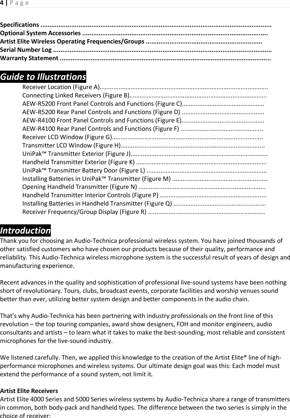
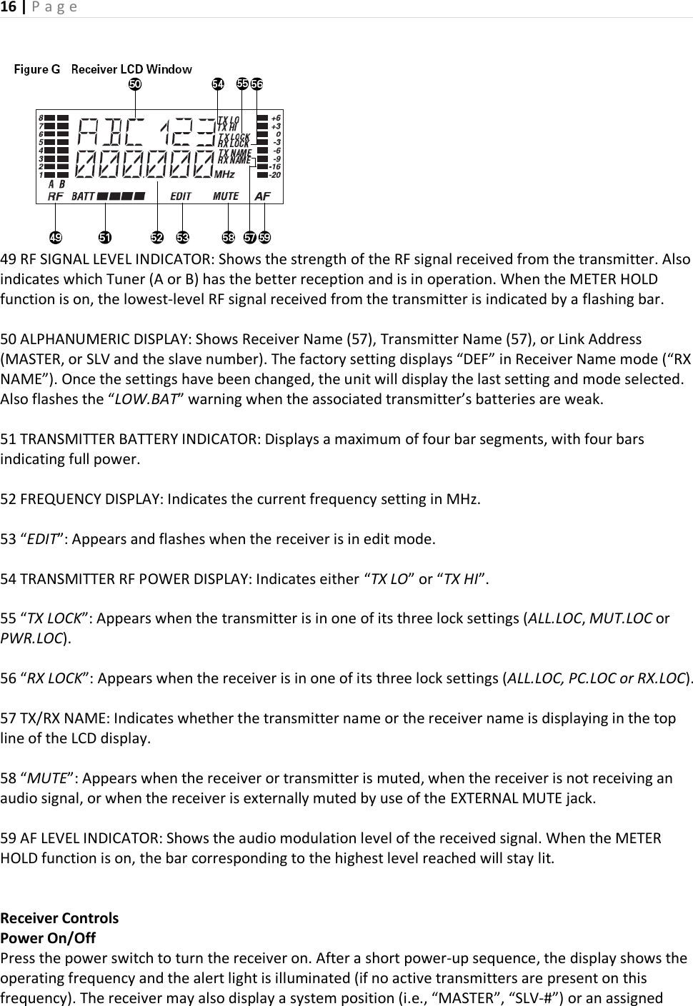
![15 | P a g e 39 MOUNTING ADAPTERS: For mounting the receiver in any standard 19" rack. Attach to the receiver with the screws supplied. (Use an optional AT8628a joining-plate kit to mount two AEW-R4100 receivers side by side.) Receiver Controls and Functions (Continued) Figure F AEW-R4100 Receiver Rear Panel 42 43 44 45 46 47 48 Rear Panel Controls and Functions (Fig. F) 40 ANTENNA INPUT JACK: BNC-type antenna connector for Tuner “B.” Attach the antenna directly, or extend it with a low-loss antenna cable. See the “Antennas” section on page [--] for more details. 41 INSTRUMENT OUTPUT JACK: 1/4" phone jack. Can be connected to an aux-level input of a mixer, guitar amp or tape recorder. On the AEW-R4100, this is an unbalanced TS phone jack. 42 AF OUTPUT ATTENUATOR: Three-position switch adjusts audio output level of both audio output jacks with attenuation of 0 dB, –6 dB or –12 dB. 43 MIC OUTPUT JACK: XLRM-type connector. A standard 2-conductor shielded cable can be used to connect the receiver output to a balanced microphone-level input on a mixer or integrated amplifier. 44 GROUND LIFT SWITCH: Disconnects the ground pin of the balanced output jack (43) from ground. Normally, the switch should be to the right (ground connected). If hum caused by a ground loop occurs, slide switch to the left (ground lifted). 45 LINK IN JACK: Connect provided cable to this jack with the index mark on the plug aligned toward the screw head above the jack. The receiver with a Link In and no Link Out connection is the “Master” unit. 46 LINK OUT JACK: Connect provided cable to this jack with the index mark on the plug aligned toward the screw head above the jack. The receiver with a Link Out and no Link In connection is the last unit in a multi-unit system. 47 ANTENNA INPUT JACK: Connector for Tuner “A.” Attach the antenna directly, or extend it with a low-loss antenna cable. 48 AC POWER INPUT: IEC-type connector for 100V–240V AC, 50/60 Hz power input. No adjustment for mains voltage/ frequency is necessary. 50 54 55 56 Figure G Receiver LCD Window](https://usermanual.wiki/Audio-Technica/T5000AD/User-Guide-1249198-Page-15.png)
![17 | P a g e transmitter or receiver name (if this feature has been set up—the display recalls the setting from the last time power was applied). Refer to page [--] on setting up receiver names or page [--] on setting up transmitter names. Level This control is used to set a comfortable listening level for the headphone jack. Turn the control clockwise to increase the level. LCD Window The LCD (Liquid Crystal Display) window provides visual indication of key operating and configuration parameters. It is also used in conjunction with the Mode/Set and Up/Down arrow buttons to change user-configurable functions. Alert Light (LED) The alert light illuminates to indicate to the user that something needs attention; for example, the transmitter batteries are low, or the transmitter is muted or turned off. Refer to page [--] for a complete description of alert light indications. Mode/Set Button The Mode/Set button has different functions depending on the status of the receiver. Two distinct operations are associated with this button: Touch: A momentary press of the Mode/Set button. It is used to enter Menu mode, to enter Edit mode, or to Escape without making any changes to current settings. Hold: A press and hold (about two seconds) of the Mode/Set button. It is used to accept a new setting when the receiver is in Edit mode or to save the current settings to one of the five user-defined name presets or the internal memory location (“NAME?”). Up/Down Arrow Buttons The Up/Down arrow buttons are used in conjunction with the Mode/Set button to scroll through the function menu in Menu mode or through the available choices for a given function in Edit mode. When the receiver is in normal operating mode, the Up/Down arrow buttons scroll through Receiver Address (“MASTER” or “SLV-#”), Receiver Preset Name, or Transmitter Preset Name. How to change receiver settings Enter Menu mode With the receiver in the normal operating mode, touch the Mode/Set button. The top line of the receiver display shows “FRQ” preceded by one, two, or three asterisks. Touch the Up/Down arrow buttons to scroll through the available functions that may be changed. (See the chart on page [--] for a list of functions and display indication.) Note that the display’s lower line indicates the current setting for a given function. Enter Edit mode When the function to be edited is displayed, touch the Mode/Set button. The small word “EDIT” flashes in the bottom of the display, indicating Edit mode.](https://usermanual.wiki/Audio-Technica/T5000AD/User-Guide-1249198-Page-17.png)
![22 | P a g e desired second character; touch the Mode/Set button once to accept it and move to the third position. Repeat this selection process until the character for the sixth position has been selected. b4. Once the sixth character has been selected as desired, hold the Mode/Set button until “STORED” appears in the window. This stores the custom Name with the associated function choices and returns the unit to normal operation. The display shows the custom name in the top line. Note: If a correction or change is desired while entering characters, simply touch the Mode/Set button once when the sixth (last) character has been reached. The window will flash “ESCAPE.” Touch the Mode/Set button once more to start the name-entry process over at the first character. (To leave any characters as they are, simply touch Mode/Set once to skip over them.) Available receiver Name character choices: A …through… Z, __ (underscore) … (space) … [ (left bracket) … ] (right bracket), * … + … -- … / , 0 …through… 9, | … < … > … ? Receiver Controls and Functions (Continued) To load (recall) a Preset: 1. Touch the Mode/Set button once to move to Menu mode. 2. Touch the Up arrow twice. LCD top line shows “PRESET.” 3. Touch the Mode/Set button once. “LOAD” (or “STORE”) appears in the LCD. 4. If needed, touch the Up arrow once to change the selection to “LOAD.” 5. Hold the Mode/Set button. The name of the currently loaded Preset appears on the second line of the LCD. 6. Touch the Up or Down arrow to cycle through the available choices, stopping on the desired choice. 7. Hold the Mode/Set button until “LOADED” appears briefly in the LCD. The receiver reverts to normal operation with the selected preset’s functions loaded. The top display line indicates the loaded preset and the bottom line the current frequency.](https://usermanual.wiki/Audio-Technica/T5000AD/User-Guide-1249198-Page-22.png)
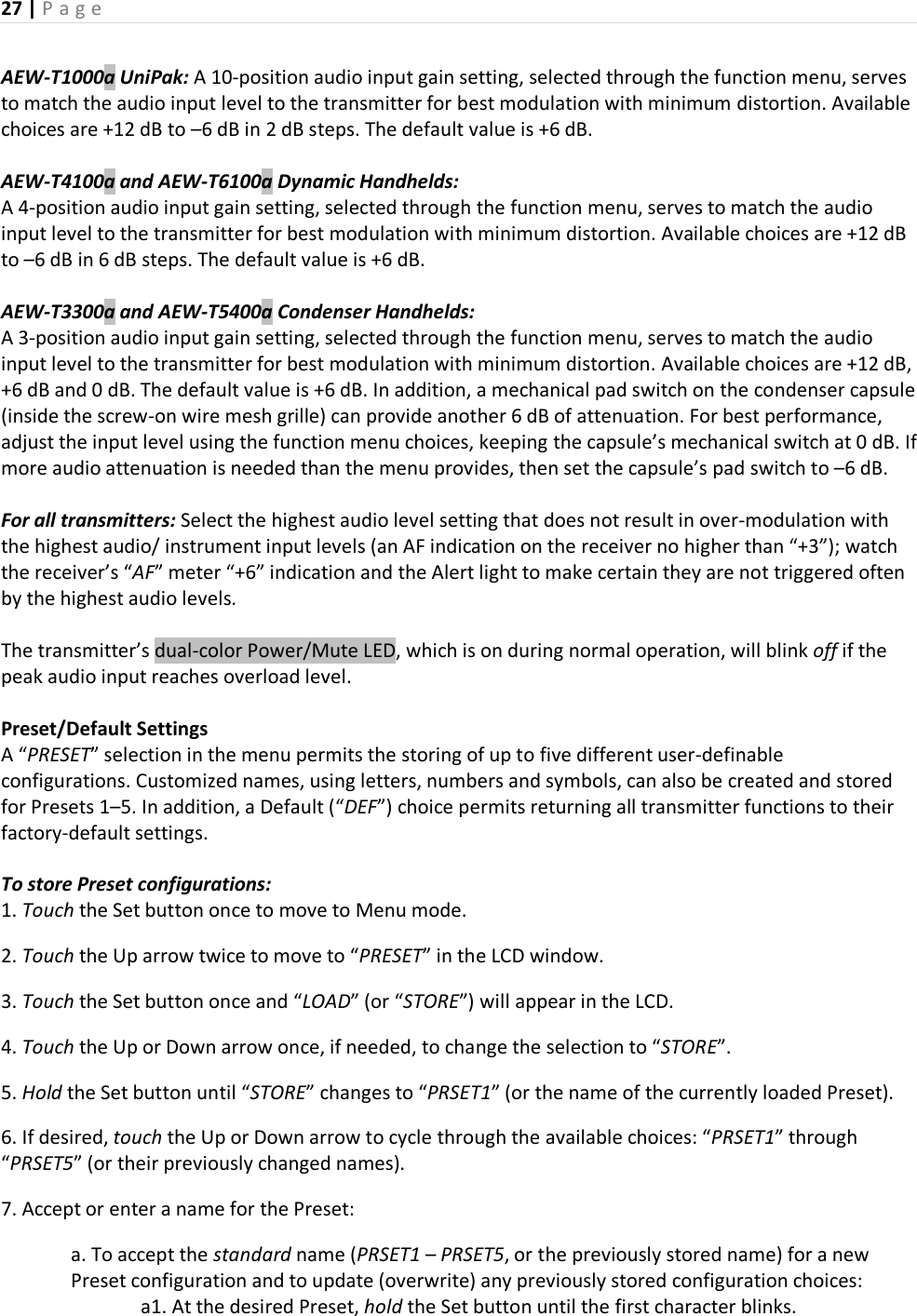
![24 | P a g e Hold: A press and hold (about two seconds) of the Mode/Set button. It is used to accept a new setting when the receiver is in Edit mode or to save the current settings to one of the five user-defined name presets or the internal memory location (“NAME?”). LCD Window The backlit Liquid Crystal Display presents a great deal of setup and operating information clearly and conveniently (Figure H). The LCD in the transmitters is designed for greatest contrast and best viewing with the window rotated somewhat away from the viewer (about 30 degrees), not straight-on, for a more convenient holding/viewing position. Power/Mute Button The transmitters have a combination Power and Mute switch (Figure J/K). When used in combination with the programmed choices explained below, the various functions available to the transmitter user may be tailored to fit personal preferences or particular situations. Power On/Off To turn the transmitter on, hold the Power/Mute button until the dual-color Power/Mute LED lights green and the backlit LCD window comes on (about 1–2 seconds). The operating frequency shows in the window after the power-up sequence. To turn the transmitter off, hold the Power/Mute button again, until the dual-color Power/Mute LED and the LCD window are extinguished (about 1–2 seconds). The LCD window shows “PWR.OFF” before shutdown. Mute On/Off When the transmitter is muted, it produces RF with no audio signal modulation. When the transmitter is un-muted, it produces both RF and audio. To mute the transmitter (cut off the audio, but continue the RF output), touch the Power/Mute button once. The Power/Mute LED turns red, and a small “MUTE” appears in the LCD window, just below the frequency (Figure H-2). To un-mute the transmitter (restore the audio), touch the Power/Mute button once again. The Power/Mute LED turns green, and the “MUTE” disappears from the LCD window. [Change to copy in Figure H: Add an “a” after the product number (AEW-T1000a) in figure H]](https://usermanual.wiki/Audio-Technica/T5000AD/User-Guide-1249198-Page-24.png)
![25 | P a g e [Changes to Figure J: Add an “a” after product number (AEW-T1000a – on transmitter) in figure j; illustrate new battery door; at top, callout should read Power/Mute LED not Power-on LED.] smitter Controls and [Change to Figure K: At bottom on figure K, callout should read Power/Mute LED not Power-on LED] Transmitter Controls and Functions (Continued) Power/Mute Locks Programmable Power/Mute Locks limit the functioning of the Power/Mute button as desired for particular users and/or applications. Power can be locked On; Mute can be locked Off. Selection of the desired locks, if any, is made through the function menu:](https://usermanual.wiki/Audio-Technica/T5000AD/User-Guide-1249198-Page-25.png)
![26 | P a g e Setting Description NO.LOC The normal Power and Mute functions are fully operational. ALL.LOC Power is locked On and Mute is locked Off when “ALL.LOC” is applied. When in the ALL.LOC mode, the transmitter may be turned off by (1) re-accessing the .LOC Menu and changing the setting, (2) pressing and holding the Up arrow button and the Set button at the same time, until the power goes off, or (3) removing and re-installing the batteries. When the transmitter is turned on again, it will power up in the NO.LOC mode. [Note; item 2 is not working in our sample.] MUT.LOC In this mode, the audio cannot be muted (Mute function is locked Off). The Power functioning is unaffected. “Mute” Note: If ALL.LOC or MUT.LOC is applied while the transmitter is muted, pressing the Power/Mute button once will return the transmitter to un-muted operation; thereafter the Mute function is disabled (Mute Off) until the .LOC setting is changed again. PWR.LOC Power is locked On when “PWR.LOC” is applied. The Mute functioning is unaffected. When in the PWR.LOC mode, the transmitter may be turned off by: (1) Re-accessing the .LOC Menu and changing the setting, (2) Pressing and holding the Up arrow button and the Set button at the same time, until the power goes off, or (3) Removing and re-installing the batteries. When the transmitter is turned on again, it will power up in the NO.LOC mode. [Note: item 2 is not working in our sample.] Note: Only the ALL.LOC or PWR.LOC Power function will change when batteries are removed; NO.LOC and MUT.LOC settings remain stored in memory. If an action is attempted that currently is locked out, the transmitter LCD will briefly display “LOCKED”, then return to its previously displayed contents. Whenever any lock condition is applied to a transmitter, its associated receiver will display a small “TX LOCK” in the LCD window, just to the right of the frequency. Audio Input Selector The UniPak™ body-pack transmitter provides input connections for both low-impedance (Lo-Z) microphones and high-impedance (Hi-Z) instruments. A wide range of Audio-Technica Wireless Essentials® microphones and cables is available pre-terminated with the appropriate professional latching connector. (See page [--].) Selection of the desired input – microphone or instrument – is made through the function menu. Depending upon the input selected, a small “MIC” or “INST” will continue to show in the LCD window, just below the frequency. (In the handheld transmitters, “MIC” will always show in the LCD window.) Setting Audio Input Level](https://usermanual.wiki/Audio-Technica/T5000AD/User-Guide-1249198-Page-26.png)
![28 | P a g e a2. Hold the Set button again until “STORED” appears in the window. This stores the standard Preset name with the associated function choices and returns the transmitter to normal operation. b.To enter a custom name for a Preset: b1. At the desired Preset, hold the Set button until the first character blinks. b2. Using the Up or Down arrow, move through the available characters (see box below) until the desired character is reached. Touch an arrow button for single steps, or hold it down to scroll through the characters at increasing speed. b3. Touch the Set button once to accept the first character and move to the second character, which now is blinking. Use an Up/Down arrow to find the desired second character; touch the Set button once to accept it and move to the third position. Repeat this selection process until the character for the sixth position has been selected. (It is not necessary to change or step through all six characters before storing the result. At any point in the process, simply hold the Set button until “STORED” appears in the window.) b4. Once the sixth character has been selected as desired, hold the Set button until “STORED” appears in the window. This stores the custom Name with the associated function choices and returns the transmitter to normal operation. Note: If a correction or change is desired while entering characters, simply touch the Set button once when the sixth (last) character has been reached. The window will flash “ESCAPE.” Touching the Set button once more will start the name-entry process over at the first character. (To leave any characters as they are, simply touch the Set 20 button once to skip over them.) Available transmitter Name character choices (listed in the Up-arrow direction): A …through… Z, __ (underscore) … (space), [ (left bracket) … ] (right bracket), * … + … -- … /, 0 …through… 9, | … < … > … ? To load (recall) a Preset: 1. Touch the Set button once to move to Menu mode. (The window changes to frequency, if Name had been displayed.) 2. Touch the Up arrow twice to move to “PRESET” in the LCD window. 3. Touch the Set button once. “LOAD” (or “STORE”) appears in the LCD.](https://usermanual.wiki/Audio-Technica/T5000AD/User-Guide-1249198-Page-28.png)
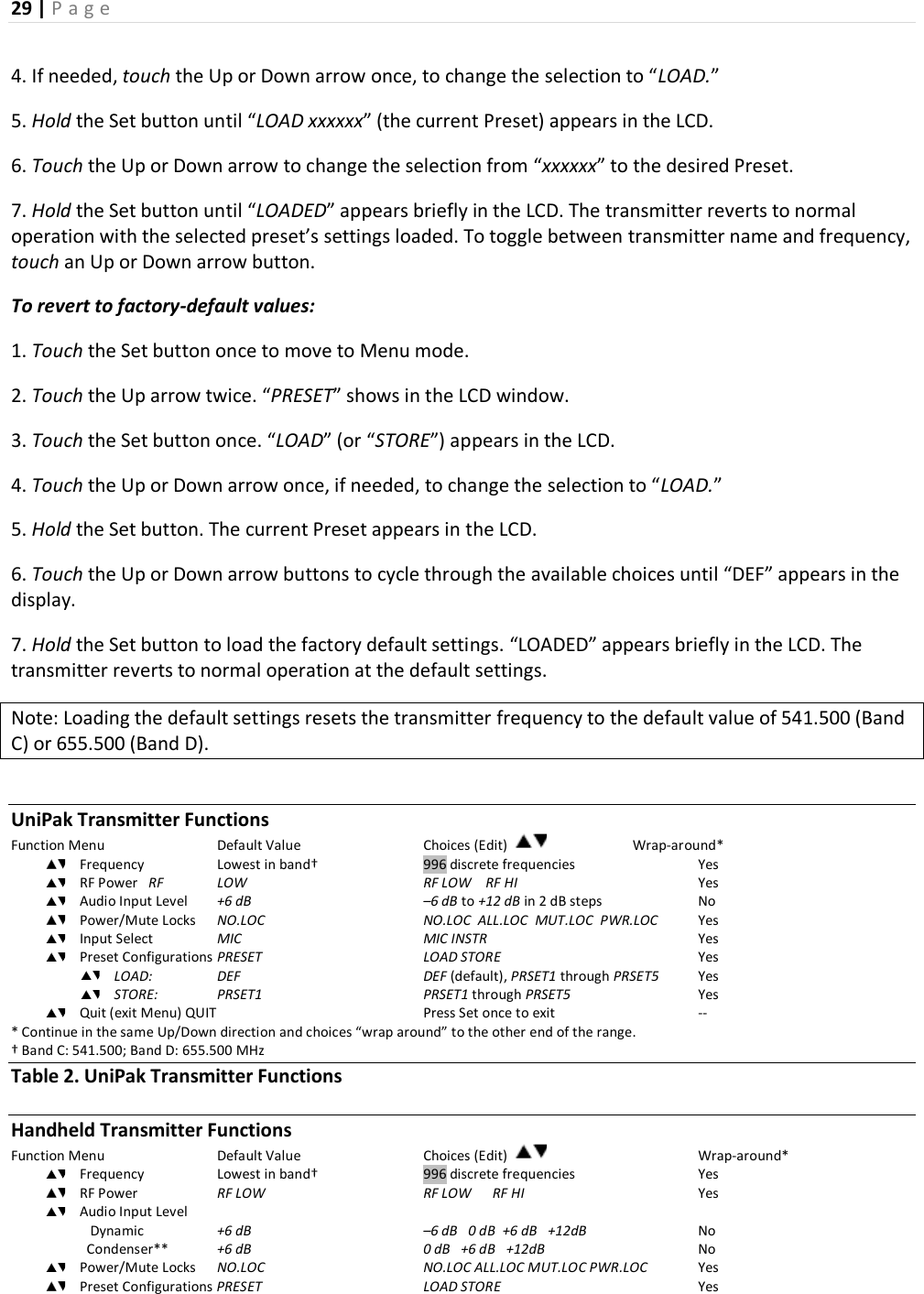
![30 | P a g e LOAD: DEF DEF (default), PRSET1 through PRSET5 Yes STORE: PRSET1 PRSET1 through PRSET5 Yes Quit (exit Menu) QUIT Press Set once to exit -- * Continue in the same Up/Down direction and choices “wrap around” to the other end of the range. ** Additional 6 dB pad switch on capsule. † Band C: 541.500; Band D: 655.500 MHz Table 3. Handheld Transmitter Functions Transmitter Setup Battery Selection and Installation Each transmitter uses two 1.5V AA batteries, not included. Alkaline type is recommended. Always replace both batteries. Make certain the transmitter power is Off before replacing batteries. UniPak™ Transmitter Battery Installation 1.Open the battery compartment door as follows: Slide door lock down to the unlocked position. Pinch the release arrows together to open the compartment. (Fig. L) 2. Observe correct polarity as marked on the metal contacts on the door and carefully insert two fresh 1.5V AA alkaline batteries (Figure M). 3. Close the door, making certain the latch clicks securely in place. 4. Slide the door lock up to the locked position. Figure L [NOTE: This is new – from 3000 Series owner’s manual] Figure M [NOTE: This is new – from 3000 Series owner’s manual]](https://usermanual.wiki/Audio-Technica/T5000AD/User-Guide-1249198-Page-30.png)
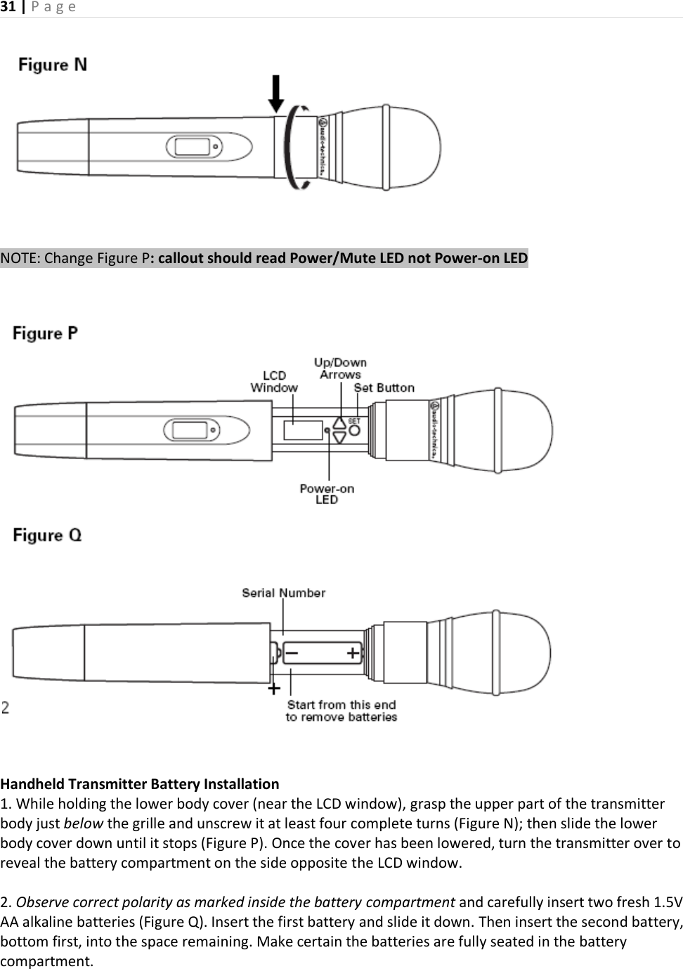
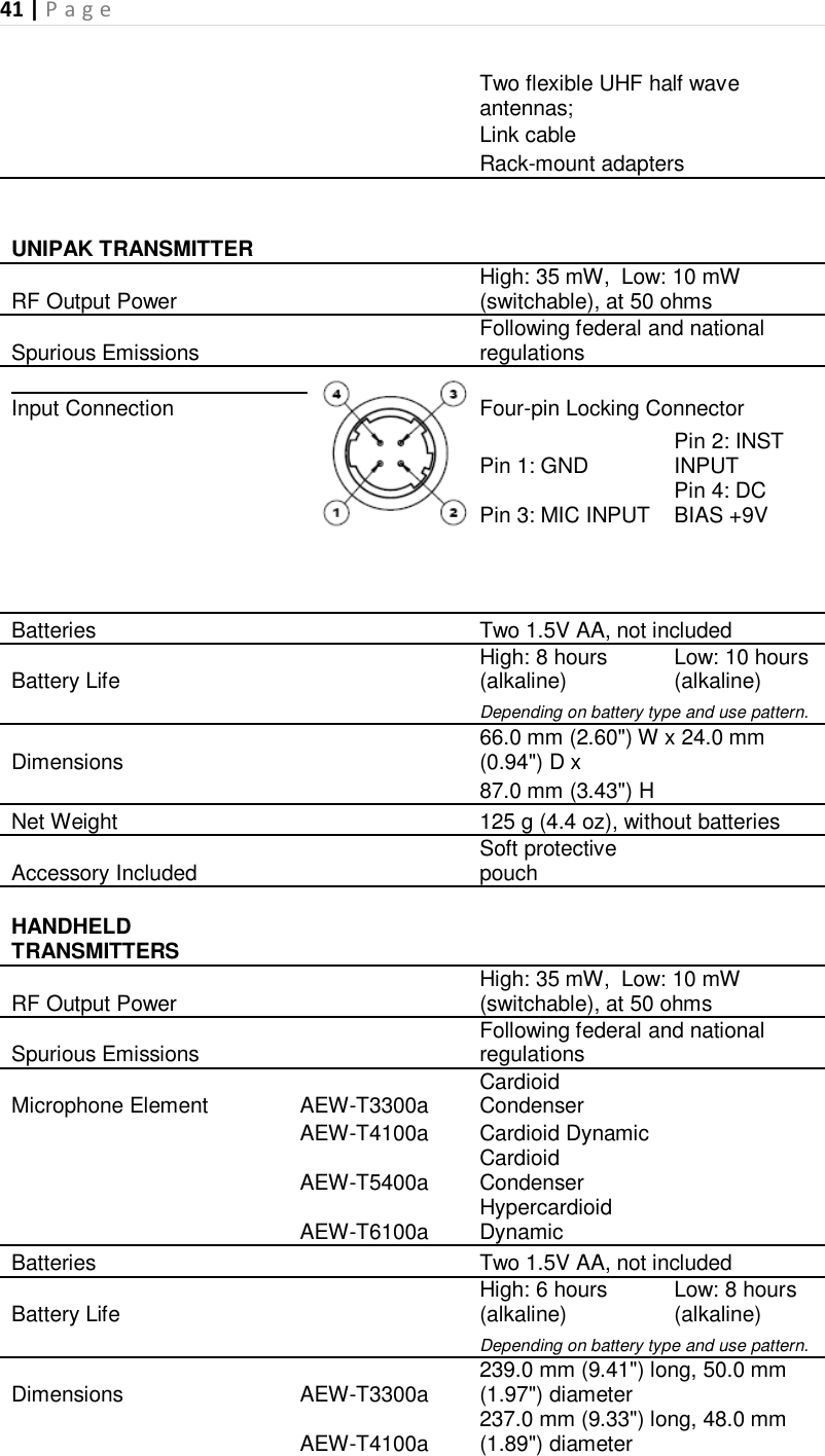
![32 | P a g e 3. Slide the lower body cover back up the body, then screw the housing together. Do not overtighten. Note: Remove batteries from the handheld transmitter starting at the bottom (– end) of the top battery (Figure Q). The top (+ end) of the top battery is captured in a recess and will not come straight out. Battery Condition Indicator After the batteries are installed, turn the power on by pressing and holding the Power/Mute button. The small dual-color Power/Mute LED (see Figure J/K on page [--].) should light and the LCD window should come on. If this does not happen, the batteries are installed incorrectly or they are dead. The transmitter’s “fuel gauge” battery indicator displays a maximum of four bar segments. When the LCD flashes “LOW.BAT”, the batteries should be replaced immediately to ensure continued operation. (The receiver also displays the transmitter’s battery condition in the LCD window with bar segments; the Alert indicator and a flashing “LOW.BAT” come on to warn of a low-battery condition.) Transmitter Setup (Continued) UniPak Transmitter Input Connection Connect an audio input device (microphone or guitar cable) to the audio input jack on the transmitter. A number of Audio-Technica professional microphones and cables are available separately, pre-terminated with a UniPak input connector. The cable connector latches automatically when inserted into the transmitter jack. To unlatch and remove the connector, simply pull up on the connector’s knurled metal collar. UniPak Transmitter Antenna The AEW-T1000a transmitter includes two field-replaceable antennas. A flexible-wire antenna is supplied mounted on the transmitter, while a separate short, helical antenna is supplied with the accessories. Either antenna simply screws into the transmitter’s antenna fitting. Check the installed antenna occasionally to make certain it is snugly attached (only finger-tight). The helical antenna is more convenient physically but may not have the operating range of the wire antenna. The wire antenna should extend, at its full length, from the transmitter. If the received signal is marginal, experiment with different transmitter positions on your body or instrument; try the wire antenna; or try repositioning the receiver. Do not attempt to modify either transmitting antenna. Replace them only with the same parts, available from the Audio-Technica Service Department. Handheld Transmitter Antenna The antenna for the handheld mic/transmitter is in the black, non-metallic section at the bottom of the unit (see Figure K on page [--]). For best results, hold the mic/transmitter naturally, around its painted metal case. Holding or otherwise covering the antenna housing may reduce operating range. UniPak Transmitter Mounting Clip The UniPak transmitter’s mounting clip may be installed with the case positioned either “up” or “down,” depending upon which is preferred for the particular application. To turn the clip around, spring the ends of the clip out of the two holes on the sides of the transmitter case (see Figure J on page [--]) and reinstall it facing in the opposite direction. System Operation Artist Elite wireless receivers and transmitters are extremely versatile components with many operating features and functions, some of which are not obvious. As a result, we suggest the following approaches to assure a “comfort level” with any new equipment:](https://usermanual.wiki/Audio-Technica/T5000AD/User-Guide-1249198-Page-32.png)
![33 | P a g e 1. Begin using a single receiver/transmitter pair at their Default (“DEF”) settings, to become familiar with equipment functions and operation before doing any customizing. (If the Default frequency is not usable in your area, change the frequency to one that is suitable.) 2. Before installing/starting up a large multi-channel system, explore the functions and operation of only two or three receiver/transmitter pairs together. The details of setting up and operating a multi-channel system vary greatly in complexity, depending upon the number of receivers and nature of the system. Because the feature-rich nature of AEW units can greatly increase this complexity, we suggest starting with a simpler, straightforward setup and use to become familiar with the equipment and its capabilities. Single AEW-R4100 receiver system: Begin using a receiver and transmitter at their Default (“DEF”) settings, to become familiar with equipment functions and operation before doing any customizing. (If the Default frequency is not usable in your area, manually change only the frequency to one that is suitable.) Single AEW-R5200 receiver system (two channels): Start out using only Channel 1, treating this the same as the single AEW-R4100 above. Multiple-receiver system with link cables only: The link cables provide data and control between receivers. The IntelliScan™ feature scans for clear channels and assigns non-conflicting frequencies to all linked receivers. (If IntelliScan is not used, the receiver frequencies may all be set individually/manually, as with any standard receiver, selecting frequencies that are within the same IntelliScan groups listed on page [--].) Multiple-receiver system with Ethernet-connected computer interface: Refer to the separate AEW Control Interface manual for setup and operation of a computer-based system. Basic hardware aspects of the receivers, and all transmitter setup/operating information, are in the manual you are now reading. Basic Operation – Single AEW-R4100 receiver system: Turn down the AF Level of the mixer or amplifier. Switch on the receiver. Do not switch on the transmitter yet. Turning on the Receiver The Alert indicator and the LCD window lights up; the normal operation LCD display appears after 1–2 seconds. If any of the bars show in the “RF” bar-graph meters, there may be RF interference in the area. If this occurs, select another frequency as explained below. (If the Meter Hold function has been selected, one of the RF bars in each column will be flashing, indicating the lowest RF levels received.) Selecting/Setting Receiver Frequency Selection of the desired operating frequency is made through the function menus. There must be no local interference on that frequency. If the Default frequency (lowest in band) happens not to be usable, the receiver frequency may be set manually, or by using the IntelliScan function.](https://usermanual.wiki/Audio-Technica/T5000AD/User-Guide-1249198-Page-33.png)
![34 | P a g e • Manual frequency selection: Adjust the receiver frequency as detailed in the next section. • IntelliScan frequency selection: The receiver’s IntelliScan function may be employed to select a usable operating frequency automatically, as detailed in the section following on page [--]. Note: Once the receiver frequency is set, the associated transmitter must be set manually to the receiver’s exact frequency. See page [--] for the correct procedure. Setting Receiver Frequency Manually Touch: A momentary press of the Mode/Set button. It is used to enter Menu mode, to enter Edit mode, or to Escape without making any changes to current settings. Hold: A press and hold (about two seconds) of the Mode/Set button. It is used to accept a new setting when the receiver is in Edit mode or to save the current settings to one of the five user-defined name presets or the internal memory location (“NAME?”). 1. Touch the Mode/Set button once. “FRQ” appears on the first line of the LCD window with the current frequency setting on the second line. (The receiver is now in Menu mode.) 2. Touch the Mode/Set button again. The small flashing word “EDIT” appears at the bottom of the window. (The receiver is now in Edit mode.) 3. Use the Up/Down arrow buttons to change the first three digits (MHz) to the desired frequency. Choose a frequency appropriate for your area, avoiding frequencies with active TV channels. Press either arrow for single steps, or hold down either arrow for rapid cycling through the band. Frequencies “wrap around” to the other end of the range when the top or bottom of the band is reached. 4. Press the Mode/Set button once to set the first three digits to the desired frequency. 5. Use the Up/Down arrow buttons to change the second three digits (kHz) to the desired frequency. Again, be certain to choose a frequency appropriate for your area, avoiding frequencies with active TV channels. 6. To activate this frequency selection, hold the Mode/Set button until the word “STORED” appears in the receiver’s window. (If you do not wish to complete this particular selection, just press the Mode/Set button once. The word “ESCAPE” will appear briefly in the window and the receiver will return to the Menu mode.) Note: The top line of the LCD indicates when frequencies belong to IntelliScan groups. Asterisks (*) are displayed in front of “FRQ” to indicate membership in one of more of the three groups (Figure R on page [--]). See page [--] for frequency group listings. 7. When finished entering a frequency, touch the Up arrow button once. The display reads “QUIT.” There are several ways to quit, depending on whether the current Name is to be retained or the frequency stored to a user preset. See page [--] for help with Quitting and saving changes.](https://usermanual.wiki/Audio-Technica/T5000AD/User-Guide-1249198-Page-34.png)
![35 | P a g e To quickly store the new frequency into the “NAME?” location, touch the Mode/Set button. The receiver shows “NAME?” in the top line and the new frequency in the bottom line. Note: You must now set the transmitter to the exact same frequency for the system to operate! System Operation (Continued) Note: An asterisk in two or more locations indicates this frequency is in more than one group. Setting Receiver Frequency Using IntelliScan Single-receiver systems (either an AEW-R4100 or an AEW-R5200): Turn down the AF level of the associated mixer or amplifier. Make certain that any AEW transmitters are turned off. (Other RF-generating devices in the area should be turned on, if possible.) 1. Touch the Mode/Set button once to enter the Menu mode. (On an AEW-R5200, use Channel 1 to perform the IntelliScan for both channels.) 2. Touch the Down arrow once. The display shows “SCAN.” 3. Hold the Mode/Set button to start the scan. The second line displays “------” during the scan and then briefly displays “SCAN OK” when the scan is successfully completed. 4. The display on the receiver then shows “RESET NAMES.” The receiver remains in this state (system is muted) until one of the following steps is completed: a. To accept and use this frequency with the currently loaded/named preset, touch the Mode/Set button. The LCD briefly displays “STORED” and reverts to normal operation. At this point, the display shows the receiver name/preset currently loaded. (Note: This frequency is now stored with the associated named preset and is recalled when that preset is reloaded.) b.To accept and use this frequency and store it in the special “NAME?” location, hold the Mode/Set button. The LCD displays “NAME?” on the top line. (Note: Doing this allows a new frequency to be used without affecting previously stored preset data. However, the receiver shows “NAME?” instead of the preset’s name.) To store this frequency along with other settings into one of the user presets, refer to the instructions on page [--].](https://usermanual.wiki/Audio-Technica/T5000AD/User-Guide-1249198-Page-35.png)
![36 | P a g e IMPORTANT! If one of the above steps (a or b) is not completed, the receiver will remain in the “RESET NAMES” state indefinitely (system is muted), and it will not automatically back out to normal operating mode. Multiple-receiver systems: Turn down the AF level of the associated mixer or amplifier. Make certain that any AEW transmitters are turned off. (Other RF-generating devices in the area should be turned on, if possible.) 1. Make certain all the receivers are connected (daisy-chained) with link cables. The receiver with only a Link In (no Link Out connection) becomes the Master receiver. (See “Link connections” on page [--].) 2. Switch on all the slave receivers first; switch on the Master receiver last. Alternatively, all receivers can be turned on simultaneously, as when using AC power plug strips controlled by a single AC switch. (If an AC power or link connection is interrupted, even briefly, all receivers must be turned off and the power-up sequence repeated to assure complete system control.) 3. Using controls on the Master receiver, follow all the steps listed for single-receiver systems to assign compatible frequencies for all receivers by using IntelliScan. 4. The display on the Master shows “RESET NAMES”, and the display on each slave shows “SCAN” and the new frequency. The receivers remain in this state (system is muted) until one of the following steps is completed to accept the new frequency plan: a. To accept and use this frequency plan with the currently loaded/named presets, touch the Mode/Set button. If a user preset was previously loaded on the receiver, the LCD briefly displays “STORED” and reverts to normal operation. The LCD then displays the previously loaded user preset or receiver name and the new frequency. (Note: This frequency is now stored with the associated named preset and is recalled when that preset is reloaded.) If no user preset was loaded (i.e., the default settings were in effect), the LCD shows “NAME?” and the new frequency. b.To accept and use this frequency and store it in the special “NAME?” location, hold the Mode/Set button. The LCD displays “NAME?” on the top line. (Note: Doing this allows a new frequency to be used without affecting previously stored preset data. However, the receiver shows “NAME?” instead of the preset’s name.) To store this frequency along with other settings into one of the user presets, refer to the instructions on page [--]. Note: These changes affect all linked receivers. IMPORTANT! If one of the above steps (a or b) is not completed, the Master and all linked slave receivers will remain in the “RESET NAMES” state indefinitely (system is muted) and will not automatically back out to normal operating mode. Note: A “SCAN ERROR” message may be attributable to one or more of the following: The link connection was broken somewhere in the chain. The power to one or more of the linked receivers was turned off. Not enough available frequencies existed for IntelliScan to assign all receivers a frequency. If IntelliScan cannot locate enough available frequencies, it will set as many as it can on the linked receivers.](https://usermanual.wiki/Audio-Technica/T5000AD/User-Guide-1249198-Page-36.png)
![37 | P a g e System Operation (Continued) Turning on the Transmitter Turn on the transmitter by holding the Power/Mute button (see Figure J/K on page [--]) for a second or two, until the dual-color Power/Mute indicator lights green and the backlit LCD display comes on. (When using a handheld transmitter, unscrew and slide down the lower body cover, as shown in Figures N/P on page [--].) Setting Transmitter Frequency Touch: A momentary press of the Mode/Set button. It is used to enter Menu mode, to enter Edit mode, or to Escape without making any changes to current settings. Hold: A press and hold (about two seconds) of the Mode/Set button. It is used to accept a new setting when the receiver is in Edit mode or to save the current settings to one of the five user-defined name presets or the internal memory location (“NAME?”). 1. Touch the Set button once. The small word “MENU” appears above the frequency. Touch the Set button again and the small flashing word “EDIT” appears to the right of “MENU.” 2. Use the Up/Down arrow buttons to change the first three digits (MHz) to the desired frequency. 3. Press Set button once to set the first three digits to the desired frequency. 4. Use the Up/Down arrow buttons to change the second three digits (kHz) to the desired frequency. 5. To activate this frequency selection, press and hold the Set button until the word “STORED” appears in the transmitter’s window. (If you do not wish to complete this particular selection, just press the Set button once. The word “ESCAPE” will appear briefly in the window and the transmitter will return to the Menu mode.) 6. When finished entering a frequency, touch the Up arrow button once to move to “QUIT.” Then touch the Set button once to exit the menu. The word “MENU” in the transmitter window disappears, indicating the return to normal operation. 7. If desired, assign a standard or custom Preset Name at this time as described on page [--] (To store Preset configurations), so this particular configuration can be recalled in the future. If a new name is not assigned, the transmitter will continue to operate on this frequency (and with these settings) until some other change in settings is made. When the transmitter is switched on and in normal operation, the receiver’s two “RF” signal-level bar meters will display from bottom to top, with more bars indicating increased signal reception. For optimum performance, at least four bars, and preferably five or more bars, on at least one of the RF indicators should be displayed at all times. Setting Levels Correct adjustment of transmitter audio input, receiver audio output, and mixer/amplifier input and output levels is important for optimum system performance.](https://usermanual.wiki/Audio-Technica/T5000AD/User-Guide-1249198-Page-37.png)
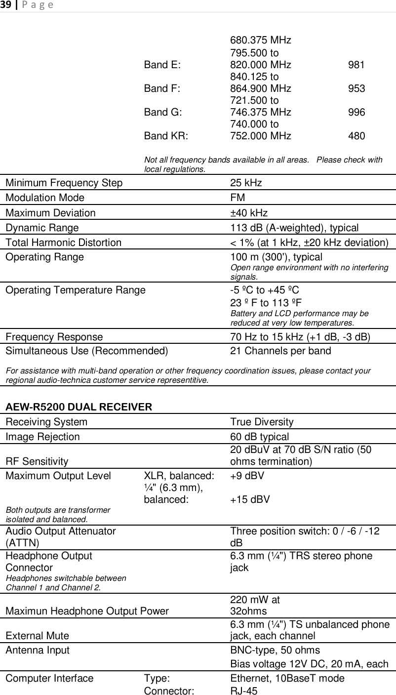
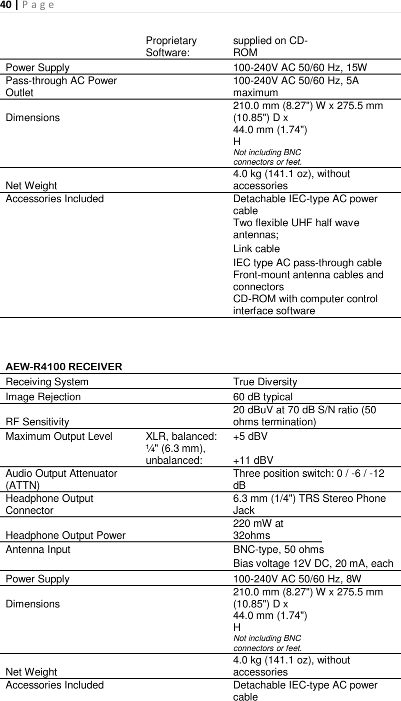
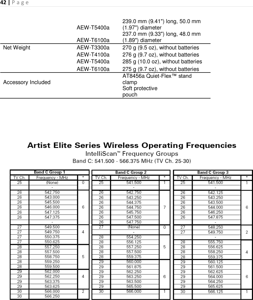
![38 | P a g e Setting Transmitter Audio Input Level Multiple-position audio input gain settings, selected through the function menu, serve to match the audio input level to the transmitter for best modulation and highest signal-to-noise ratio with minimum distortion. Select the highest setting that does not result in over-modulation with the highest audio/instrument input levels (an AF indication on the receiver no higher than “+3”); watch the receiver’s “AF” bar-graph “+6” indication and the Alert light to make certain that they are not triggered by the highest audio levels. Also, the transmitter’s dual-color LED Power/Mute indicator, which is on during normal operation, will blink off if the peak audio input reaches overload level. Available Level Settings AEW-T1000a UniPak™: Choices are +12 dB to –6 dB in 2 dB steps. The default setting is +6 dB. AEW-T4100a/6100a Dynamic Handhelds: Choices are +12 dB, +6 dB, 0 dB and –6 dB. The default setting is +6 dB. AEW-T3300a/5400a Condenser Handhelds: Choices are +12 dB, +6 dB and 0 dB. The default setting is +6 dB. A mechanical switch on the condenser capsule activates a 6 dB pad. For best performance, adjust the input level using the function menu choices first, keeping the capsule’s pad switch at 0 dB. If more audio attenuation is needed, set the capsule’s switch to –6 dB. RF Power Adjustment RF power may be set to “RF HI” (35 mW nominal) or “RF LOW” (10 mW nominal) through the function menu. The default setting is “RF LOW.” While the Hi setting normally provides maximum operating range, the Low setting will help extend battery life. The Low setting may also be preferred when using multi-channel systems, or when operating very close to the receiver, to reduce the possibility of interference or overload. RF Interference Wireless frequencies are shared with other radio services. According to Federal Communications Commission regulations, “Wireless microphone operations are unprotected from interference from other licensed operations in the band. If any interference is received by any Government or non-Government operation, the wireless microphone must cease operation....” If you need assistance with operation or frequency selection, please contact your dealer or the Audio-Technica professional division. Extensive information on using wireless microphones is also available on the Audio-Technica Web site at www.audio-technica.com. AEW Specifications [NOT FINAL – Created 2/4/10, before TP stage] AEW Specifications OVERALL SYSTEM UHF Operating Frequencies Frequency Range Number of Frequencies Band C: 541.500 to 566.375 MHz 996 Band D: 655.500 to 996](https://usermanual.wiki/Audio-Technica/T5000AD/User-Guide-1249198-Page-38.png)
![43 | P a g e Optional System Accessories [include 5-year warranty]](https://usermanual.wiki/Audio-Technica/T5000AD/User-Guide-1249198-Page-43.png)