Audio Technica T5201EF2 Body Pack Transmitter User Manual
Audio-Technica Corporation Body Pack Transmitter
UserManual.wiki
>
Audio Technica
>
T5201EF2 User Manual
>
User manual
Contents
1.
safety leaflet
2.
User manual
User manual
Navigation menu
Upload a User Manual
Namespaces
Wiki Guide
HTML
PDF
Info
Views
User Manual
Discussion / Help
Navigation
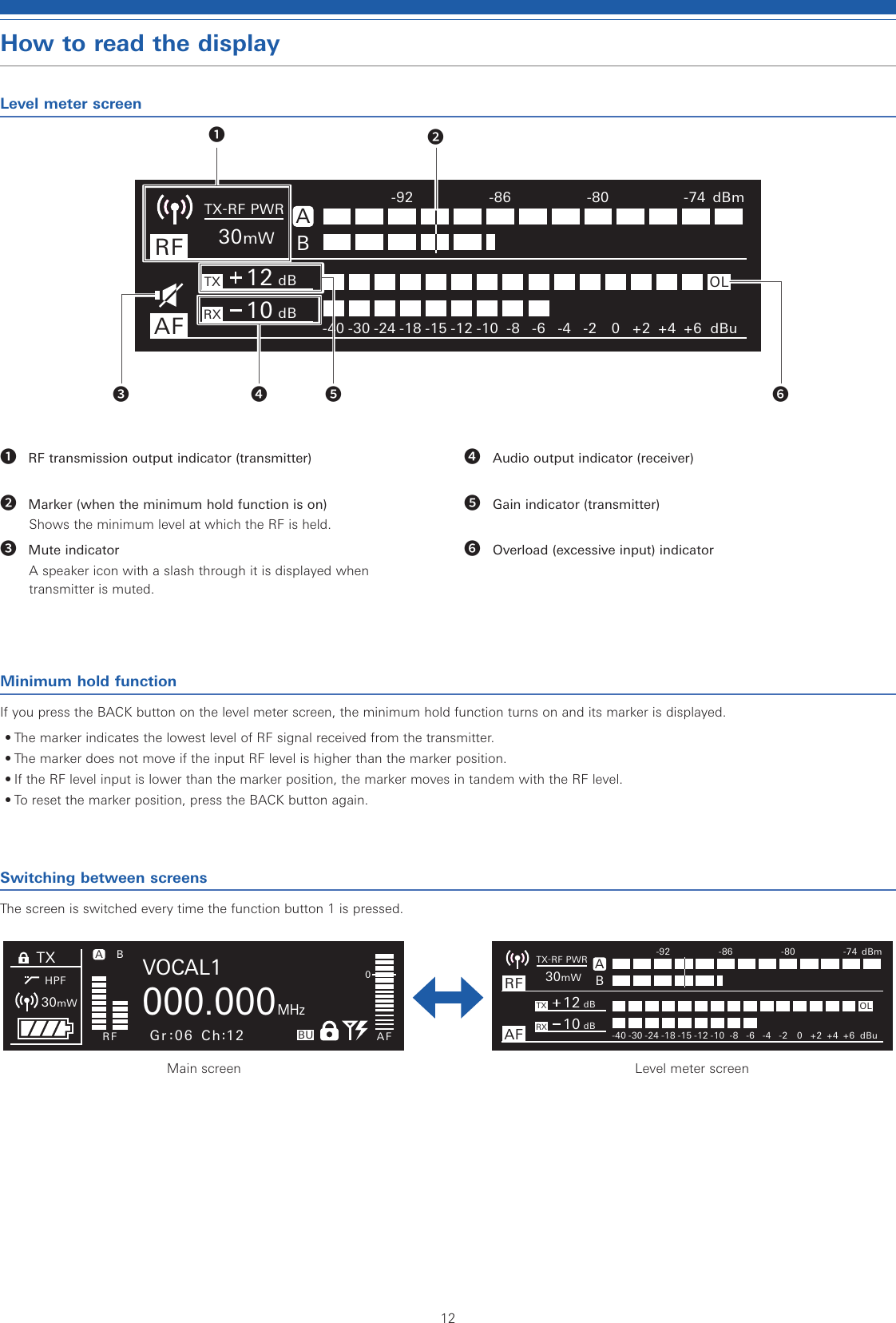
![16Setting ATW-R5220/ATW-R5220DANList of setting itemsFREQUENCY MANUAL Set the operating frequency.Gr/ChNAME Set the channel name.AUDIO Set the audio output level.SCAN Scan for open channels.TX SYNC Set transmitters via IR SYNC.SQUELCH AUTO Set the squelch level.MANUALUTILITIES LOCK Set this function to prevent the receiver settings from being changed.ANT PWR Set whether to turn power on or off to the antenna input terminals.Gr/Ch Edit the groups/channels 01 to 10.BACKUP FREQSet the backup frequency.AF METER Switch the level meter on the main screen between receiver and transmitter.BRIGHTNESSSet the display brightness.ACCESS Set the user access level.RESET This returns the receiver settings to their factory defaults.VERSION This function displays product information such as the version of the receiver.NETWORK DEVICE ID Set the receiver's ID No.IP SETTING Set the IP.REMOTE CTRLSet the remote control.SYSLOG Set whether to send the log message to the Syslog server.DISCOVERY Set automatic detection by the application.NTP Set the NTP (Network Time Protocol).MAC ADDRESSDisplay the MAC address.TOOLS WALK TEST Record for 90 sec. the RF level being received.MONITOR MODEThis mode will enable monitoring with headphones only. (The audio OUT and DANTE OUT will be muted.)DANTE* INFO Display the device name and channel label.IP SETTING Set the DANTE's IP.MAC ADDRESSDisplay the MAC address.VERSION This function displays product information such as the version of the receiver.* ATW-R5220DAN onlySetting the operating frequencyManual setting1. From the menu screen, turn the control dial, select [FREQUENCY] and then press the control dial.2. Select [MANUAL] and press the control dial.3. Turn the control dial to set the first 3 digits. When finished setting them, press the control dial.4. Turn the control dial to set the last 3 digits. When finished setting them, press the control dial.• The setting is complete.Setting by group/channel1. From the menu screen, turn the control dial, select [FREQUENCY] and then press the control dial.2. Select [Gr/Ch] and press the control dial.3. Turn the control dial to set the group. When finished setting it, press the control dial.4. Turn the control dial to set the channel. When finished setting it, press the control dial.• The setting is complete.Setting the channel (receiver) nameThe following characters can be entered:• The maximum number of characters that can be entered is 8.Alphabetic (uppercase letters)NumericSymbols (+, −, #, &, period) Space1. From the menu screen, turn the control dial, select [NAME] and then press the control dial.2. Turn the control dial, select the desired character and then press the control dial.• The character is input and the cursor moves.3. Repeat the operation in Step 2 to enter all characters.4. Turn the control dial, select [End] and then press the control dial.• The setting is complete.](https://usermanual.wiki/Audio-Technica/T5201EF2.User-manual/User-Guide-3931694-Page-17.png)
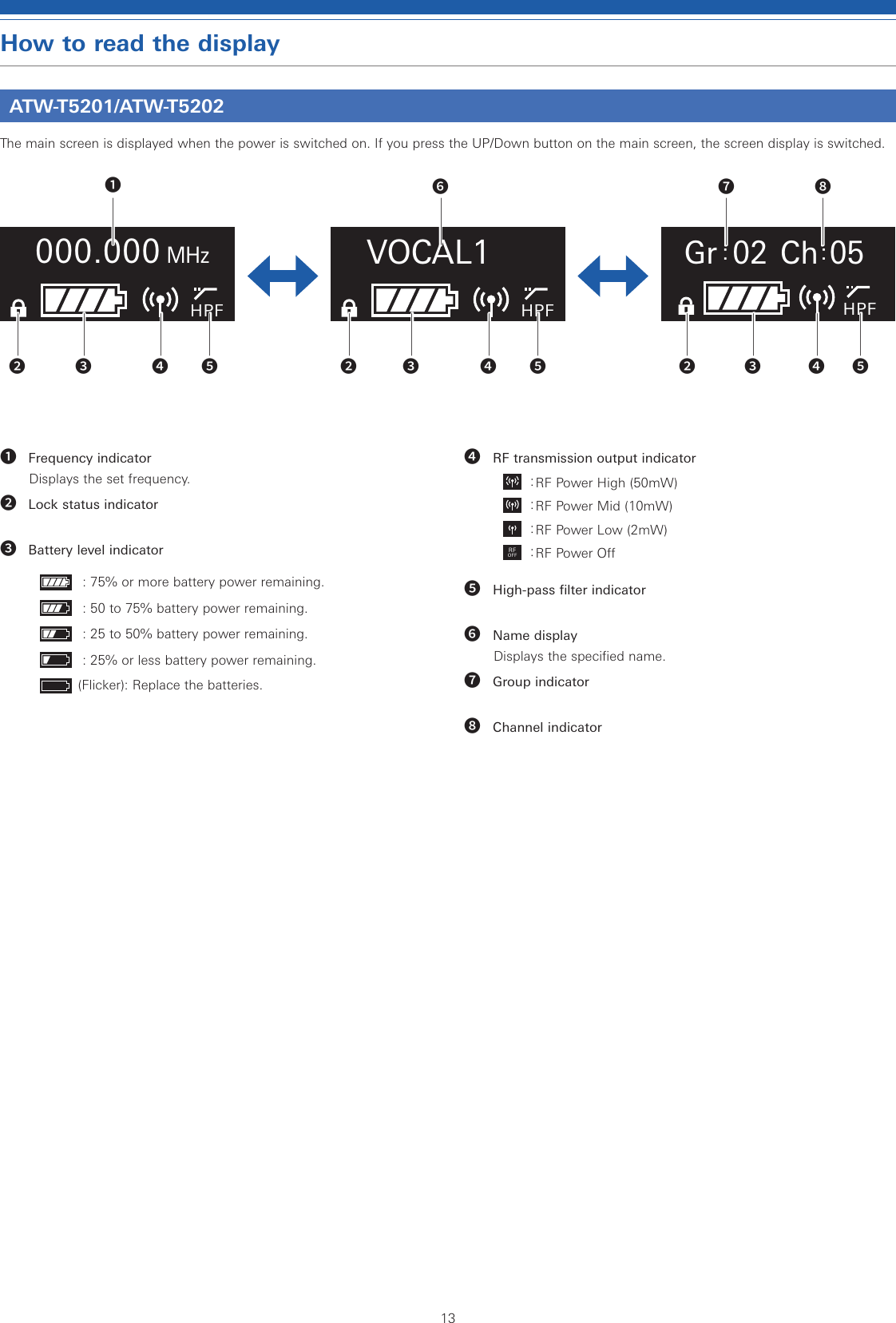
![17Setting ATW-R5220/ATW-R5220DANSetting the audio output level1. From the menu screen, turn the control dial, select [AUDIO] and then press the control dial.2. Turn the control dial to set the audio output level.• The level changes 2dB +/- each time you turn the control dial.• It can be set from -60 to 0dB.3. Press the control dial.• The setting is complete.Scanning for open channelsScan for unused channels in the current environment for use.1. From the menu screen, turn the control dial, select [SCAN] and then press the control dial.2. Turn the control dial to select the group you want to scan. After selecting a group, press the control dial.• Selecting "ALL" will scan all the groups.3. Turn the control dial to select the preferred threshold. selecting the threshold, press the control dial.• You can select [Normal], [High] or [Low] sensitivity.High: Prioritize the number of channels.NormalLow: Prioritize stable operation.• Scan starts.Selecting [ALL]:4. Confirm the scan result, select the group and then press the control dial.5. Select the channel selection method, and them press the control dial.• When selecting [Manual] and pressing the control dial, available channels and frequencies are shown in a list. Turn the control dial, select an available channel and then press the control dial. The setting is complete.• When selecting [Find Best] and pressing the control dial, the optimum channel and frequency are shown. Turn the control dial, select [Set] and then press the control dial. The setting is complete.Selecting the group you want to scan:4. Confirm the scan result by selecting [OK] and then pressing the control dial.• If you want to scan over again, select [Retry].5. Select the channel selection method, and them press the control dial.• When selecting [Manual] and pressing the control dial, available channels and frequencies are shown in a list. Turn the control dial, select an available channel and then press the control dial. The setting is complete.• When selecting [Find Best] and pressing the control dial, the optimum channel and frequency are shown. Turn the control dial, select [Set] and then press the control dial. The setting is complete.Setting transmitters via IR SYNCThis function allows you to make transmitter settings on the receiver and then automatically configure the transmitter via IR SYNC. The following are the available settings and setting values:Settings Setting valuesFreq Current setting value, NoChangeName Current setting value, NoChangeRF Pwr Low:2mW, Mid:10mW, High:50mW, NoChangeGain -10 to +20dB, NoChangeSens.* 0, +10dB, NoChangeLock Lock, Unlock, NoChangeBatt Alkaline, Ni-MH, NoChangeHPF OFF, ON, NoChange* ATW-T5201 only1. From the menu screen, turn the control dial, select [TX SYNC] and then press the control dial.2. Turn the control dial to select a setting you would like to sync to the transmitter and then press the control dial.3. Turn the control dial to select the setting value and then press the control dial.4. Repeat Steps 2 and 3 for each setting you would like to sync to the transmitter.5. Turn the control dial, select [SYNC START] and then press the control dial.• Communication function is in standby. Refer to "Using IR SYNC" (p. 28) for subsequent steps.](https://usermanual.wiki/Audio-Technica/T5201EF2.User-manual/User-Guide-3931694-Page-18.png)
![18Setting ATW-R5220/TW-R5220DANSetting the squelch levelSetting automatically1. From the menu screen, turn the control dial, select [SQUELCH] and then press the control dial.2. Turn the control dial, select [AUTO] and then press the control dial.3. Turn the control dial, select [Normal], [High] or [Low] and then press the control dial.• You can select one from [Normal], [High] or [Low].High: Prioritize the sound/voice quality.NormalLow: Prioritize the available range.• Scan starts.• If an error message is displayed, change the operating frequency. The error indicates that the current frequency is already in use or that there is excessive noise.4. Scan starts. Press the control dial.• The setting is complete.Setting manually1. From the menu screen, turn the control dial, select [SQUELCH] and then press the control dial.2. Turn the control dial, select [MANUAL] and then press the control dial.3. Turn the control dial to select the value you wish to set.• The meter indicates the RF level.• It can be set from levels 1 to 16.• While the available range of the transmitter becomes wider as the squelch level is lower, there may be cases when noises occur under the influence of other radio waves. While the available range of the transmitter becomes narrower as the squelch level is made higher, noises are less likely to occur due to the less influence of other radio waves.4. Press the control dial.• The setting is complete.Setting the system-related functionsSetting the lockSet this function to prevent the receiver settings from being changed.• The default setting is [Unlock].1. From the menu screen, turn the control dial, select [UTILITIES] and then press the control dial.2. Turn the control dial, select [LOCK] and then press the control dial.3. Turn the control dial to select [Lock] or [Unlock], and then press the control dial.• The setting is complete.Setting the antenna powerSet whether to turn power on or off to the antenna input terminals.• The default setting is [OFF].• If set to [ON], power is supplied to both antennas A and B.1. From the menu screen, turn the control dial, select [UTILITIES] and then press the control dial.2. Turn the control dial, select [ANT PWR] and then press the control dial.3. Turn the control dial, select [ON] or [OFF] and then press the control dial.• The setting is complete.](https://usermanual.wiki/Audio-Technica/T5201EF2.User-manual/User-Guide-3931694-Page-19.png)
![19Setting ATW-R5220/ATW-R5220DANSetting group/channnel editingSetting group/channelGroups/Channels 01 to 10 can be edited.1. From the menu screen, turn the control dial, select [UTILITIES] and then press the control dial.2. Turn the control dial, select [Gr/Ch EDIT] and then press the control dial.3. Turn the control dial, select [EDIT] and then press the control dial.4. Turn the control dial, select a channel and then press the control dial.5. Turn the control dial, select [ON] or [OFF] and then press the control dial.• If you select [OFF], the group can not be used.6. Turn the control dial, select a channel and then press the control dial.7. Turn the control dial, select [EDIT] and then press the control dial.• By pressing [SET], you can set the frequency of the selected channel.• If you press [RESET], the frequency of the selected channel becomes blank.8. After setting all channels, turn the control dial, select [Sync] or [Save] and then press the control dial.• If you press [Save], the setting is completed.• If you press [Sync], the screen turns to an IR SYNC standby screen. Refer to "Using IR SYNC" (p. 28) for subsequent steps.Syncing the Group/ChannelThe Groups/Channels that have been set with [EDIT] can be set to the transmitter in groups with IR SYNC.1. From the menu screen, turn the control dial, select [UTILITIES] and then press the control dial.2. Turn the control dial, select [Gr/Ch EDIT] and then press the control dial.3. Turn the control dial, select [Gr/Ch SYNC] and then press the control dial.4. Turn the control dial to select group and then press the control dial.• The screen turns to an IR SYNC standby screen. Refer to "Using IR SYNC" (p. 28) for subsequent steps.Setting the backup frequency modeIf you set the backup frequency in advance, you can switch the frequency of the transmitter and receiver with the transmitter. It is convenient to set this function when you want to switch the frequency easily.• The default setting is [OFF].1. From the menu screen, turn the control dial, select [UTILITIES] and then press the control dial.2. Turn the control dial, select [BACKUP FREQ] and then press the control dial.3. Turn the control dial, select [ON] and then press the control dial.4. Turn the control dial, select [Manual] or [Gr/Ch] and then press the control dial.• If you select [Manual], you can set the frequency.• If you select [Gr/Ch], you can set the group/channel.5. After setting each item, turn the control dial, select [Set] or [Sync] and then press the control dial.• If you press [SET], the setting is completed but you must still sync the setting with the transmitter or set the backup frequency manually on the transmitter in order to use the backup frequency.• If you press [Sync], the screen turns to an IR SYNC standby screen. Refer to "Using IR SYNC" (p. 28) for subsequent steps.](https://usermanual.wiki/Audio-Technica/T5201EF2.User-manual/User-Guide-3931694-Page-20.png)
![20Setting ATW-R5220/ATW-R5220DANSetting the AF level meter on the main screenSwitch the AF level meter on the main screen between [Receiver (Rx)] and [Transmitter (TX)].• The default setting is [RX].1. From the menu screen, turn the control dial, select [UTILITIES] and then press the control dial.2. Turn the control dial, select [AF METER] and then press the control dial.3. Turn the control dial, select [RX] or [TX] and then press the control dial.• The setting is complete.Setting the display brightnessThe default setting is [High].1. From the menu screen, turn the control dial, select [UTILITIES] and then press the control dial.2. Turn the control dial, select [BRIGHTNESS] and then press the control dial.3. Turn the control dial, select [High] or [Low] and then press the control dial.• The setting is complete.Setting the user access levelSet the user access level.• The default setting is [Free Tuning].1. From the menu screen, turn the control dial, select [UTILITIES] and then press the control dial.2. Turn the control dial, select [ACCESS] and then press the control dial.3. Turn the control dial, select [Free Tuning] or [Group Only] and then press the control dial.Free Tuning No limitGroup Only Selection of frequency can be made only from group.• The setting is complete.ResettingThis returns the receiver settings to their factory defaults.1. From the menu screen, turn the control dial, select [UTILITIES] and then press the control dial.2. Turn the control dial, select [RESET] and then press the control dial.3. Turn the control dial, select [Yes] and then press the control dial.4. After the confirmation screen is displayed, turn the control dial again to select [Yes] and then press the control dial.• Reset starts.Checking the receiver informationThis function displays product information such as the version of the receiver.1. From the menu screen, turn the control dial, select [UTILITIES] and then press the control dial.2. Turn the control dial, select [VERSION].](https://usermanual.wiki/Audio-Technica/T5201EF2.User-manual/User-Guide-3931694-Page-21.png)
![21Setting ATW-R5220/ATW-R5220DANSetting networkBy connecting the receiver and PC, you can use the dedicated app for monitoring or controlling with the PC.Setting the receiver's ID No.1. From the menu screen, turn the control dial, select [NETWORK] and then press the control dial.2. Turn the control dial, select [DEVICE ID] and then press the control dial.3. Turn the control dial, select the device ID and then press the control dial.• The setting is complete.Setting the IP1. From the menu screen, turn the control dial, select [NETWORK] and then press the control dial.2. Turn the control dial, select [IP SETTING] and then press the control dial.3. Select an item you want to set and press the control dial.IP Mode Set how to obtain IP addresses.[Auto]: IP addresses are automatically assigned.[Static]: Set to use the specified static IP addresses.IP Address* Specify static IP addresses.Subnet Mask* Set the subnet mask.Gateway* Set the gateway.*This item can be set only when [IP Mode] is set to [Static].4. Set each item.Setting the remote control1. From the menu screen, turn the control dial, select [NETWORK] and then press the control dial.2. Turn the control dial, select [REMOTE CTRL] and then press the control dial.3. Select an item you want to set and press the control dial.Port Set the receiver's ID No.Notification Receive notifications from the receiver.LVL Notify Set whether to include the AF and RF level in the notification from the receiver during remote control.Multicast IP Set the address for multicast.Multicast Port Set the port number for multicast.4. Set each item.Setting the log messageSet whether to send the log message to the Syslog server.1. From the menu screen, turn the control dial, select [NETWORK] and then press the control dial.2. Turn the control dial, select [SYSLOG] and then press the control dial.3. Turn the control dial, select [ON] or [OFF] and then press the control dial.• The setting is complete.• Syslog is a standard for transferring log messages across IP networks. It is used for administration of computer systems and security monitoring.Setting automatic detection by the application1. From the menu screen, turn the control dial, select [NETWORK] and then press the control dial.2. Turn the control dial, select [DISCOVERY] and then press the control dial.3. Turn the control dial, select [ON] or [OFF] and then press the control dial.• The setting is complete.Setting NTPSet the NTP (Network Time Protocol).1. From the menu screen, turn the control dial, select [NETWORK] and then press the control dial.2. Turn the control dial, select [NTP] and then press the control dial.3. Select an item you want to set and press the control dial.NTP Set whether to enable or disable the NTP (Network Time Protocol).Server adrs Set the NTP server address.Port Set the NTP port number.Time Zone Set the time difference from the UTC (Coordinated Universal Time).DST Turn on/off the daylight saving time.DST Start Date Set the starting date of daylight saving time.DST Start Time Set the starting time of daylight saving time.DST End Date Set the ending date of daylight saving time.DST End Time Set the ending time of daylight saving time.4. Set each item.](https://usermanual.wiki/Audio-Technica/T5201EF2.User-manual/User-Guide-3931694-Page-22.png)
![22Setting ATW-R5220/TW-R5220DANSetting MAC address1. From the menu screen, turn the control dial, select [NETWORK] and then press the control dial.2. Turn the control dial, select [MAC ADDRESS].Using test modeUsing the walk test functionWhen using the walk test function, record for 90 sec. the RF level being received.1. From the menu screen, turn the control dial, select [TOOLS] and then press the control dial.2. Turn the control dial, select [WALK TEST] and then press the control dial.3. Select [START] and press the control dial.• Walk test starts.Setting monitor modeThis mode will enable monitoring with headphones only. (The audio OUT and DANTE OUT will be muted.)1. From the menu screen, turn the control dial, select [TOOLS] and then press the control dial.2. Turn the control dial, select [MONITOR MODE] and then press the control dial.• Monitor mode is set.Setting DANTEThis setting is used only for ATW-R5220DAN.Displaying the device name and channel label1. From the menu screen, turn the control dial, select [DANTE] and then press the control dial.2. Turn the control dial, select [INFO].Setting the DANTE's IP1. From the menu screen, turn the control dial, select [DANTE] and then press the control dial.2. Turn the control dial, select [IP SETTING] and then press the control dial.3. Select an item you want to set and press the control dial.IP Mode Set how to obtain IP addresses.[Auto]: IP addresses are automatically assigned.[Static]: Set to use the specified static IP addresses.IP Address* Specify static IP addresses.Subnet Mask* Set the subnet mask.Gateway* Set the gateway.*This item can be set only when [IP Mode] is set to [Static].4. Set each item.Setting MAC address1. From the menu screen, turn the control dial, select [DANTE] and then press the control dial.2. Turn the control dial, select [MAC ADDRESS].Checking the receiver informationThis function displays product information such as the version of the receiver.1. From the menu screen, turn the control dial, select [DANTE] and then press the control dial.2. Turn the control dial, select [VERSION].](https://usermanual.wiki/Audio-Technica/T5201EF2.User-manual/User-Guide-3931694-Page-23.png)
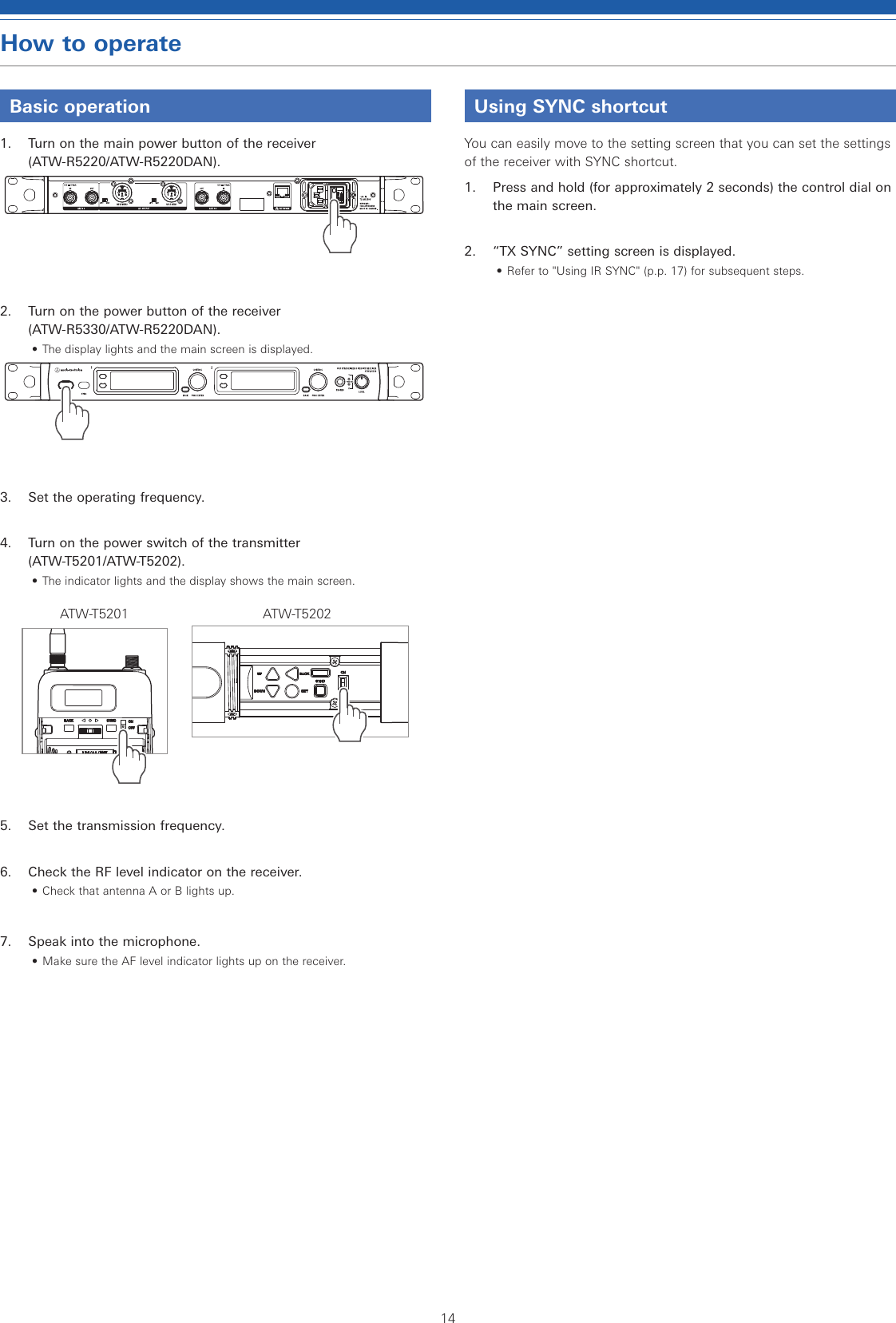
![23Settting ATW-T5201/ATW-T5202List of setting itemsFREQUENCY MANUAL Set the transmission frequency.Gr/ChNAME Set the channel name.GAIN Set the microphone input gain.SENSITIVITY* Set the gain.RF POWER Set the transmission output.HPF Set HPF (High-Pass Filter).LOCK Set a lock.TOOLS Fn BUTTON Set the function allocation for function button.TEST TONE Output a test signal from the transmitter.UTILITIES BATTERY Set the type of batteries used.LEDSet whether to constantly keep indicator turned on or off.ACCESS Set the user access level.RESET This returns the transmitter settings to their factory defaults.VERSION It shows the version of the transmitter.* ATW-T5201 onlySetting the transmission frequencySetting manually1. From the menu screen, press the UP/DOWN button to select [FREQUENCY], and then press the SET button..000MHz000FREQUENCY2. After selecting [MANUAL], press the SET button.MANUALFREQUENCY3. Press the UP/DOWN button to set the first 3 digits. After completing the setting, press the SET button.4. Press the UP/DOWN button to set the last 3 digits. After completing the setting, press the SET button.• The setting is complete.Setting by group/channel1. From the menu screen, press the UP/DOWN button to select [FREQUENCY], and then press the SET button..000MHz000FREQUENCY2. After selecting [Gr/Ch], press the SET button.Gr/ChFREQUENCY3. Press the UP/DOWN button to set the group. After completing the setting, press the SET button.4. Press the UP/DOWN button to set the channel. After completing the setting, press the SET button.• The setting is complete.Setting the channel (transmitter) nameThe following characters can be entered:• The maximum number of characters that can be entered is 8.Alphabetic (uppercase letters)NumericSymbols (+, −, #, &, period) Space1. From the menu screen, press the UP/DOWN button to select [NAME], and then press the SET button.NAME2. Press the UP/DOWN to select a desired character and press the SET button.• The character is input and the cursor moves.3. Repeat the operation in Step 2 to enter all characters.• If you don't enter 8 characters, press the UP/DOWN button and select [End] and then press the SET button.4. After entering the 8th character, press the SET button.• [End] is displayed.5. Press the SET button.• The setting is complete.](https://usermanual.wiki/Audio-Technica/T5201EF2.User-manual/User-Guide-3931694-Page-24.png)
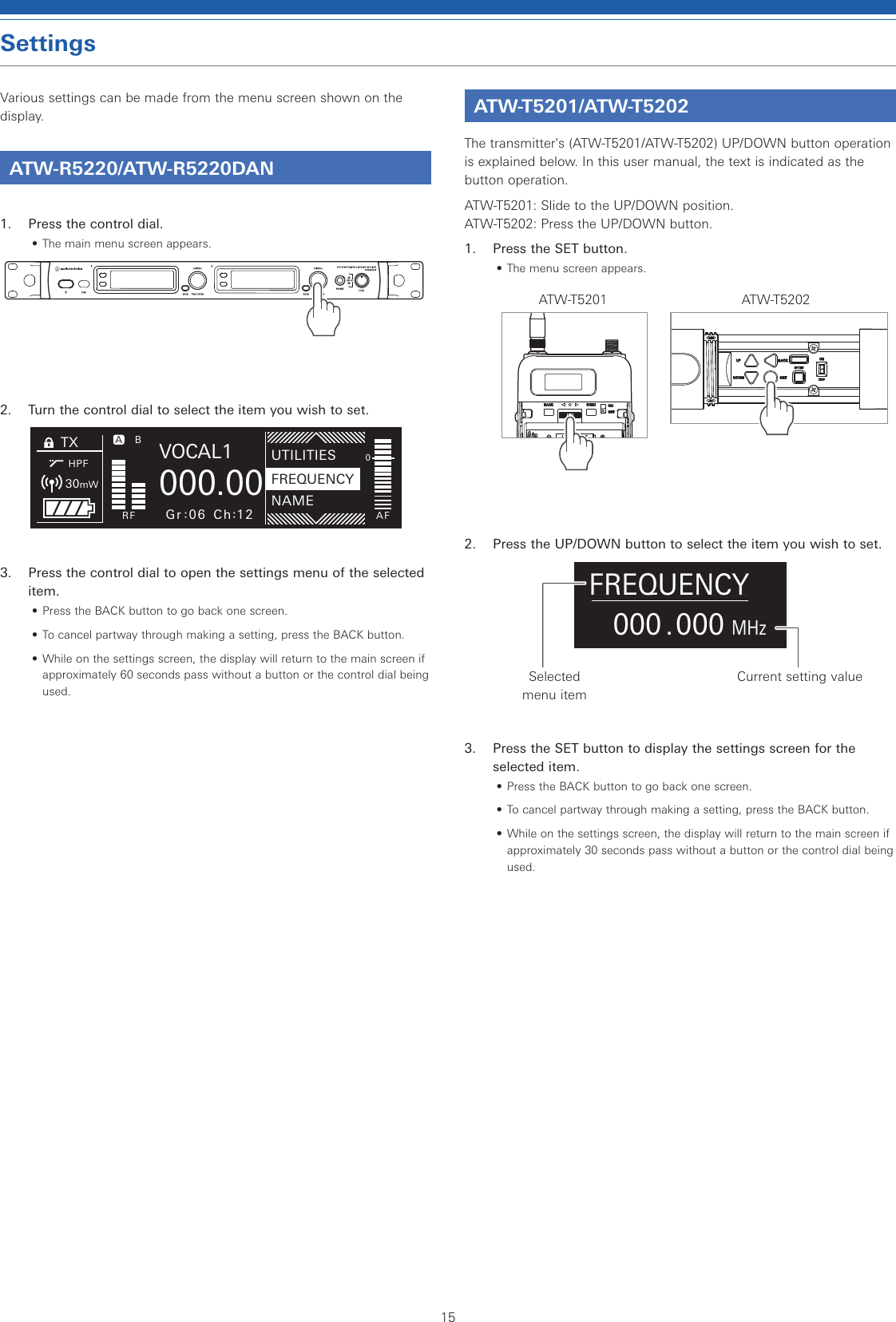
![24Settting ATW-T5201/ATW-T5202Setting the gain1. From the menu screen, press the UP/DOWN button to select [GAIN], and then press the SET button.0dBGAIN2. Press the UP/DOWN button to select the gain you wish to set.• The level changes 2dB +/- each time you press the UP/DOWN button.• It can be set from -10 to +20 dB.3. Press the SET button.• The setting is complete.Setting the microphone input gain1. From the menu screen, press the UP/DOWN button to select [SENSITIVITY], and then press the SET button.0dBSENSITIVITY2. Press the UP/DOWN button and select [0dB] or [+10dB].3. Press the SET button.• The setting is complete.Setting the RF transmission output1. From the menu screen, press the UP/DOWN button to select [RF POWER], and then press the SET button.High:50mWRF POWER2. Press the UP/DOWN button and select [High:50mW], [Mid:10mW], [Low:2mW] or [Off].3. Press the SET button.• The setting is complete.Setting HPF (High-Pass Filter)1. From the menu screen, press the UP/DOWN button to select [HPF], and then press the SET button.OHPF2. Press the UP/DOWN button to select [On] or [Off].3. Press the SET button.• The setting is complete.Setting lock1. From the menu screen, press the UP/DOWN button to select [LOCK], and then press the SET button.UnlockLOCK2. Press the UP/DOWN button to select [Lock] or [Unlock].Lock Locks transmitter buttonsUnlock Unlocks transmitter buttons3. Press the SET button.• The setting is complete.](https://usermanual.wiki/Audio-Technica/T5201EF2.User-manual/User-Guide-3931694-Page-25.png)
![25Settting ATW-T5201/ATW-T5202Setting the functionSetting the function for the function buttonSelect the function to be performed when the function button is pressed and held1. From the menu screen, press the UP/DOWN button to select [TOOLS], and then press the SET button.TOOLS2. Press the UP/DOWN button to select [Fn BUTTON], and then press the SET button.DisableFn BUTTON3. Press the UP/DOWN button to select the function you wish to set.Disable No functionMute (only for ATW-T5202)Mutes the transmitterMuteOnLock (only for ATW-T5202)Mutes the transmitter (even when transmitter buttons are locked)Bkup Freq Switches to backup frequency (When selected, set the frequency, group, and channel.)RF Off Turns off RF transmission output4. Press the SET button.• The setting is complete.Outputting a test signal from the transmitter1. From the menu screen, press the UP/DOWN button to select [TOOLS], and then press the SET button.TOOLS2. Press the UP/DOWN button to select TEST TONE], and then press the SET button.OTEST TONE3. Press the UP/DOWN button to select [On], and then press the SET button.• Outputting a test signal starts.• While outputting a test signal, a microphone input will be muted.Setting the system-related functionsSetting the battery typeSet the type of batteries used.• The default setting is [Alkaline].1. From the menu screen, press the UP/DOWN button to select [UTILITIES], and then press the SET button.UTILITIES2. Press the UP/DOWN button to select [BATTERY] and press the SET button.AlkalineBATTERY3. Press the UP/DOWN button to select the battery you wish to set.Alkaline Select when using alkaline batteries.NiMH Select when using nickel–metal hydride batteries.4. Press the SET button.• The setting is complete.• If the appropriate setting is not made for the batteries used, the battery power indicator will not display the correct information. Always set the type of battery according to the batteries used.](https://usermanual.wiki/Audio-Technica/T5201EF2.User-manual/User-Guide-3931694-Page-26.png)
![26Settting ATW-T5201/ATW-T5202Setting the indicatorThe indicator LED can be turned [On] or [Off].• The default setting is [On].1. From the menu screen, press the UP/DOWN button to select [UTILITIES], and then press the SET button.UTILITIES2. Press the UP/DOWN button to select [LED] and press the SET button.OnLED3. Press the UP/DOWN button to select [On] or [Off].4. Press the SET button.• The setting is complete.Setting the user access levelSet the user access level.• The default setting is [Free].1. From the menu screen, press the UP/DOWN button to select [UTILITIES], and then press the SET button.UTILITIES2. Press the UP/DOWN button to select [ACCESS] and press the SET button.FreeACCESS3. Press the UP/DOWN button to select [Free] or [Group].Free No limitGroup Selection of frequency can be made only from group.4. Press the SET button.• The setting is complete.ResettingThis returns the transmitter settings to their factory defaults.1. From the menu screen, press the UP/DOWN button to select [UTILITIES], and then press the SET button.UTILITIES2. Press the UP/DOWN button to select [RESET] and press the SET button.NoRESET3. Press the UP/DOWN button to select [Yes].4. When the confirmation screen is shown, press the UP/DOWN button again to select [Yes].5. Press the SET button.• Reset starts.Checking the transmitter informationThis function displays the firmware version for the transmitter.1. From the menu screen, press the UP/DOWN button to select [UTILITIES], and then press the SET button.UTILITIES2. Press the UP/DOWN button to select [VERSION] and press the SET button.• The version is shown.000.000.000VERSION](https://usermanual.wiki/Audio-Technica/T5201EF2.User-manual/User-Guide-3931694-Page-27.png)