Audio Technica T5202EF2 Handheld Transmitter User Manual
Audio-Technica Corporation Handheld Transmitter
Contents
- 1. safety leaflet
- 2. user manual.pdf
- 3. user manual
user manual
User Manual
UHF Wireless Systems
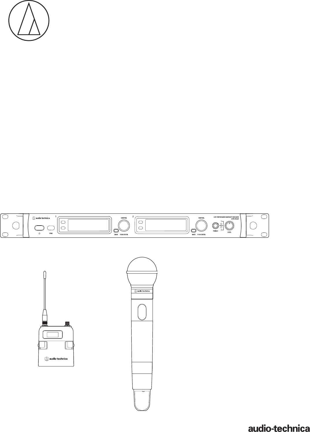
ATW-R5220
Dual Receiver
ATW-R5220DAN
Dual Receiver with Dante Output
ATW-T5201
Body-Pack Transmitter
ATW-T5202
Handheld Transmitter (without capsule)
5000 Series

1
Contents
Introduction .................................................................................2
Important information .................................................................2
Notes on use ...............................................................................4
Maintenance ................................................................................4
Part names and functions ............................................................5
ATW-R5220/ATW-R5220DAN .......................................................................... 5
ATW-T5201 ...................................................................................................... 7
ATW-T5202 ...................................................................................................... 8
How to insert batteries ................................................................9
ATW-T5201 ...................................................................................................... 9
ATW-T5202 ...................................................................................................... 9
How to attach and detach the interchangeable microphone
capsule (only for ATW-T5202) ....................................................10
How to attach ............................................................................................... 10
How to remove ............................................................................................. 10
How to read the display ............................................................11
ATW-R5220/ATW-R5220DAN ........................................................................ 11
ATW-T5201/ATW-T5202 ................................................................................. 13
How to operate ..........................................................................14
Basic operation ............................................................................................. 14
Using SYNC shortcut .................................................................................... 14
Settings .....................................................................................15
ATW-R5220/ATW-R5220DAN ........................................................................ 15
ATW-T5201/ATW-T5202 ................................................................................. 15
Setting ATW-R5220/ATW-R5220DAN .......................................16
List of setting items ...................................................................................... 16
Setting the operating frequency ................................................................... 16
Setting the channel (receiver) name ............................................................. 16
Setting the audio output level ....................................................................... 17
Scanning for open channels ......................................................................... 17
Setting transmitters via IR SYNC .................................................................. 17
Setting the squelch level ............................................................................... 18
Setting the system-related functions ............................................................ 18
Setting network ............................................................................................. 21
Using test mode ............................................................................................ 22
Setting DANTE .............................................................................................. 22
Settting ATW-T5201/ATW-T5202 ...............................................23
List of setting items ...................................................................................... 23
Setting the transmission frequency .............................................................. 23
Setting the channel (transmitter) name ........................................................ 23
Setting the gain ............................................................................................. 24
Setting the microphone input gain ............................................................... 24
Setting the RF transmission output .............................................................. 24
Setting HPF (High-Pass Filter) ....................................................................... 24
Setting lock ................................................................................................... 24
Setting the function ...................................................................................... 25
Setting the system-related functions ............................................................ 25
How to attach the transmitter (ATW-T5201) .............................27
Making connections (basic connections) ..................................27
Using IR SYNC ........................................................................... 28
Achieving stable reception ........................................................28
Rack-mounting the receiver.......................................................28
Troubleshooting .........................................................................29
ATW-R5220/ATW-R5220DAN ........................................................................ 29
ATW-T5201/ATW-T5202 ................................................................................. 29
Dimensions ................................................................................30
ATW-R5220/ATW-R5220DAN ........................................................................ 30
ATW-T5201 .................................................................................................... 31
ATW-T5202 .................................................................................................... 31
Specifications ............................................................................32
Overall system specifications........................................................................ 32
ATW-R5220/ATW-R5220DAN ........................................................................ 32
ATW-T5201 .................................................................................................... 32
ATW-T5202 .................................................................................................... 33
2
Introduction
Thank you for purchasing this Audio-Technica product.
Before using the product, read through this user manual to ensure that you will use the product correctly. Please keep this manual for future
reference.
Important information
Warning:
• To prevent fire or shock hazard, do not expose this apparatus to rain or moisture.
Caution:
• Do not expose this apparatus to drips or splashes.
• To avoid electric shock, do not open the cabinet.
• Refer servicing to qualified personnel only.
• Do not expose this apparatus to excessive heat such as that generated by sunshine, fire or other heat sources.
• Do not subject this apparatus to strong impact.
• This apparatus should be located close enough to the AC outlet so that you can easily grasp the power cord plug at any time.
• In case of emergency, disconnect the power cord plug of this apparatus quickly.
• Do not place any objects filled with liquids, such as vases, on this apparatus.
• To prevent fire, do not place any naked flame sources (such as lighted candles) on this apparatus.
• Do not install this apparatus in a confined space such as a bookcase or similar unit.
• Install this apparatus only in the places with good ventilation.
• To prevent fire, do not cover the ventilation of this apparatus with newspapers, table-clothes, curtains, etc.
• This apparatus with ClassⅠconstruction shall be connected to the AC outlet with a protective grounding connection.
• This apparatus is not disconnected from the mains as long as it is connected to the AC outlet, even if the unit itself has been turned off.
• In order to maintain proper ventilation, do not place any objects around the rear of this apparatu s.
• This apparatus should be placed at least 15 cm away from a rear wall. This apparatus should not be placed near to other electrical apparatuses.
Keep the top and sides of this apparatus at least 10 mm away from any other surface if sitting on shelving, such as an audio apparatus rack.
Failure to do so may cause this apparatus to overheat which in turn may cause it or surrounding items to catch fire.
Battery caution:
• Keep batteries out of the reach of children.
• Observe correct polarity as marked.
• Do not expose the battery to excessive heat such as sunshine, fire or the like.
• Always consider the environment issues and follow local regulations when disposing of batteries.
• Remove depleted battery immediately.
• Danger of explosion if battery is incorrectly replaced. Replace only with the same or equivalent type.
• Use only disposable LR06(AA) alkaline or Ni-MH batteries.
• Do not use new batteries and old one at the same time.
• Do not use different batteries type or model.
• Do not use a leaking battery. If battery leakage occurs, avoid contact with skin. If contact occurs, immediately wash thoroughly with soap and
water.
• If battery leakage comes into contact with your eyes, immediately flush with water and seek medical attention.
For customers in the USA/Canada
Caution:
To prevent electric shock, do not remove the cover. There are
no user-serviceable parts inside. Internal adjustments are for qualified
professionals only. Refer all servicing to qualified service personnel.
The lightning flash with arrowhead symbol, within an
equilateral triangle, is intended to alert the user to the
presence of uninsulated “dangerous voltage” within the
product's enclosure that may be of sufficient magnitude to
constitute a risk of shock to persons.
The exclamation point symbol within an equilateral
triangle is intended to alert the user to the presence
of important operating and maintenance (servicing)
instructions in the literature accompanying the
product.
CAUTION
RISK OF ELECTRIC SHOCK
DO NOT OPEN

3
Important information
Important Safety Instructions
1. Read these instructions.
2. Keep these instructions.
3. Heed all warnings.
4. Follow all instructions.
5. Do not use this apparatus near water.
6. Clean only with dry cloth.
7. Do not block any of ventilation openings. Install in accordance with the manufacturer’s instructions.
8. Do not install near any heat sources such as radiators, heat registers, stoves, or other apparatus (including amplifiers) that produce heat.
9. Do not defeat the safety purpose of the polarized or grounding plug. A polarized plug has two blades with one wider than the other. A grounding
plug has two blades and a third grounding prong. The wide blade or the third prong is provided for your safety. If the provided plug does not fit into
your outlet, consult an electrician for replacement of the obsolete outlet.
10. Protect the power cord from being walked on or pinched particularly at plugs, convenience receptacles, and the point where they exit
from the apparatus.
11. Only use attachments/accessories specified by the manufacturer.
12.
Use only with a cart, stand, tripod, bracket or table specified by the manufacturer, or sold with the apparatus. When a cart is used, use caution
when moving the cart/apparatus combination to avoid injury from tip-over.
13. Unplug this apparatus during lightning storms or when unused for long periods of time.
14. Refer all servicing to qualified service personnel. Servicing is required when the apparatus has been damaged in any way, such as power-supply cord or
plug is damaged, liquid has been spilled or objects have fallen into the apparatus, the apparatus has been exposed to rain or moisture, does not operate
normally, or has been dropped.
FCC Notice
Warning:
This device complies with Part 15 of the FCC Rules. Operation is subject to the following two conditions: (1) This device may not cause harmful
interference, and (2) this device must accept any interference received, including interference that may cause undesired operation.
Caution:
You are cautioned that any changes or modifications not expressly approved in this manual could void your authority to operate this equipment.
Wireless microphone users shall rely on the white space databases in part 15, Subpart H to determine that their intended operating frequencies are
available for unlicensed wireless microphone operation at the location where they will be used. Wireless microphone users must register with and
check a white space database to determine available channels prior to beginning operation at a given location. A user must re-check the database
for available channels if it moves to another location.
Note: This equipment has been tested and found to comply with the limits for a Class B digital device, pursuant to part 15 of the FCC Rules. These
limits are designed to provide reasonable protection against harmful interference in a residential installation. This equipment generates, uses and
can radiate radio frequency energy and, if not installed and used in accordance with the instructions, may cause harmful interference to radio
communications. However, there is no guarantee that interference will not occur in a particular installation. If this equipment does cause harmful
interference to radio or television reception, which can be determined by turning the equipment off and on, the user is encouraged to try to correct
the interference by one or more of the following measures:
- Reorient or relocate the receiving antenna.
- Increase the separation between the equipment and receiver.
- Connect the equipment into an outlet on a circuit different from that to which the receiver is connected.
- Consult the dealer or an experienced radio/TV technician for help.
For customers in Canada
IC statement
CAN RSS-Gen/CNR-Gen
This device complies with INDUSTRY CANADA R.S.S. 210. Operation is subject to the following conditions: (1) This device may not cause harmful
interference and (2) this device must accept any interference received, including interference which may cause undesired operation.
This device complies with RSS-102 radiation exposure limits set forth for an uncontrolled environment.

4
Notes on use
• Be sure to read the user manual for any microphone or cable that you attach to the product.
• Disconnect the power cable from the outlet when this product is not in use.
• Turn off the power of this product before connecting or disconnecting cables.
• If you use the product near a TV or radio antenna, you may hear unwanted noise in the television or radio. If this occurs, move the product away
from the device.
• Two waves of the same frequency can't be used simultaneously.
• Be careful of interference noise caused by the surrounding radio wave environment and use of multiple systems.
• Wireless systems may be affected by the spark noise of vehicles, dimmer of lighting apparatus, computers, office automation apparatus and
electronic musical instruments. Place and use the product where it is less likely to be affected by the above.
• Be sure to use this product in combination with components specified by our company.
• Be sure the connected cable is plugged all the way into the product.
• When you connect the product with a mixer, turn off the phantom power source.
• If you use the product close to an electronic or communications device (such as a mobile phone), the product may produce unwanted noise. If
this occurs, move the product away from the device.
• When setting up the product, make sure there are no obstacles between the transmitter and the receiver that might block the signal.
• To prevent the batteries from wearing out, turn the transmitter off when not in use.
• Over time, discoloration may occur due to ultraviolet rays (especially direct sunlight) and friction.
• It is legally prohibited to dismantle and modify this product. In addition, this product is so precisely manufactured that dismantling it could cause
electric shock, failure or fire. Never dismantle this product.
Using multiple wireless systems
• If you use more than one device at the same time, use them in the same group.
• When using multiple units simultaneously, maintain 1 meter or more between individual transmitters and 3 meters or more between transmitters
and receivers' antennas.
• When using multiple units, power on transmitters one by one, making sure there is no unwanted noise.
• When a howling (beeping or squealing) sound is produced during use, turn down the output volume of the connected mixer/amplifier.
Maintenance
• If the product becomes stained or covered with dust, be sure to disconnect the power cable before wiping it off with a dry and soft cloth.
• Do not use benzine, thinner or electrical contact cleaner, etc. They may deform or otherwise damage the product, or cause operational failure.
5
Part names and functions
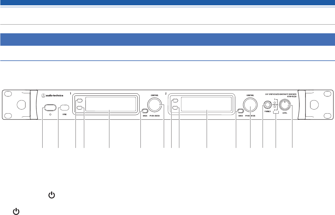
ATW-R5220/ATW-R5220DAN
Front panel
❶ Power button ( )
Use to turn the receiver on or standby.
(: Symbol indicates standby.)
❷ IR sync window
Use to IR SYNC with the transmitter (ATW-T5201, ATW-T5202).
❸ Function button 1
Press to switch the main display and the level meter display.
❹ Function button 2
Press to switch the main display..
❺ Display
Displays the receiver state and setting menus.
❻ BACK button
Press to take the display back one screen.
Returns to the Main screen when pressed and held.
❼ Control dial
Displays the setting menu when you press the dial. Turn the dial to select a setting and press to confirm.
When you press and hold the dial, “TX SYNC” setting screen is displayed.
❽ Headphone monitor(6.3 mm)output jack
This is the headphone output jack used for monitoring. It allows you to monitor receivers 1 and 2.
❾ Headphone channel indicator
Displays which receiver is being monitored, receiver 1 or 2.
❿ Headphone volume/Channel switch
Use when adjusting the volume of the headphones for monitoring.
Press and release the dial to switch between receivers 1 and 2.
• Does not affect receiver audio output level.
❷❶ ❻ ❼❸ ❹ ❺ ❸ ❹ ❽ ❾ ❿❺ ❻ ❼
6
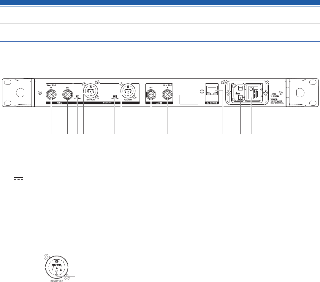
Part names and functions
Rear panel
The figure below is ATW-R5220.
❶ Antenna input jack
(: Symbol indicates direct current.)
Each jack supplies DC12 V to a connected antenna.
Additionally other compatible accessories (sold separately) can be connected.
❷ Antenna output jack
Distributes and outputs signals input to antennas A and B.
By using this jack, it is possible to connect up to seven receivers (8 total).
❸ Ground lift switch
This switch isolates the GND pin of the balanced/unbalanced output from the ground.
Normally this is kept in the GND position, but if a hum develops due to a ground loop, switch to the LIFT side.
❹ Balanced output jack (XLR 3-pin male)
GND HOT
COLD
❺ Network interface
By connecting to a PC via Ethernet, you can use the PC for monitoring or control.
In the case of ATW-R5220DAN, it will be the DANTE output port.
❻ AC inlet
Connect the power cable.
(~: Symbol indicates the current.)
❼ Main power switch
Press the main power switch to turn the power on.
Turn the main power switch on before turning the front panel power switch on.
❷❶ ❹ ❷❸❹ ❸ ❶ ❼❺ ❻
7
Part names and functions
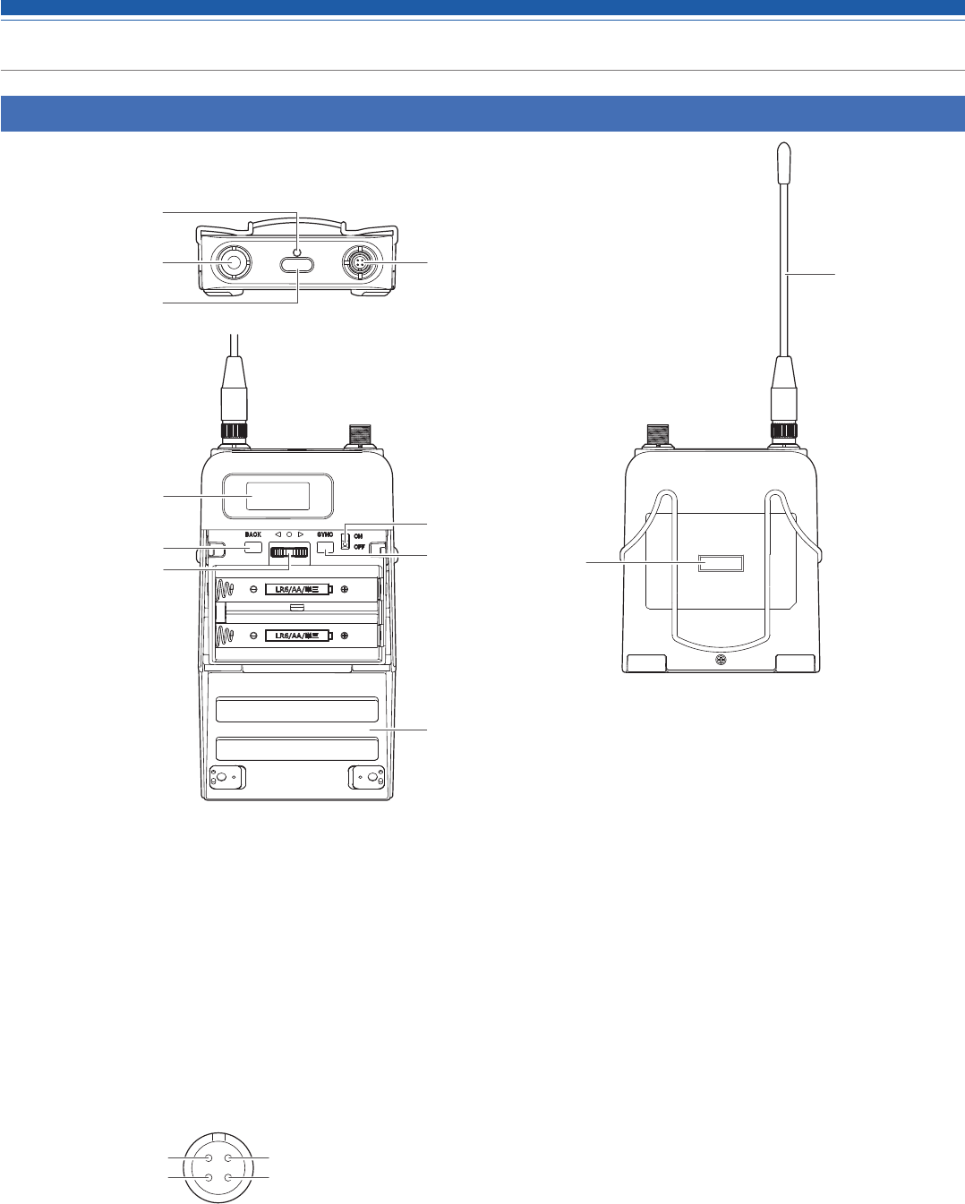
ATW-T5201
❶ Indicator
LED that shows the status of the transmitter.
When the power is turned ON: Solid green
When the transmitter is muted: Solid red
❷ Transmission antenna
❸ Function button
Press briefly to turn the screen back on if it shuts off. Press and
hold to perform preselected function.
❹ Input connector
Connect a microphone, a headworn microphone, a guitar cable,
etc.
Pin 1: GND Pin 4: +5 V output
Pin 2: Instrument input Pin 3: Microphone input
❺ Display
Shows the current status.
If no buttons are pressed for a period of 30 seconds, the display
will turn off.
❻ BACK button
Press to take the display back one screen.
Returns to the Main screen when pressed and held.
❼ Lever push switch
Use to select various settings.
UP(▶)
Turn to the right to change a selection.
DOWN(●)
Turn to the left to change a selection.
SET(◀)
Press to confirm a selection.
❽ Power switch
Use to turn the power on or off.
❾ SYNC button
Use to IR SYNC with the receiver (ATW-R5220/ATW-R5220DAN).
❿ Battery cover
⓫ IR sync window
Use to IR SYNC with the receiver.
❶
❷
❸
❹
❺
❻
❼
❽
❾
❿
⓫
❷
8
Part names and functions
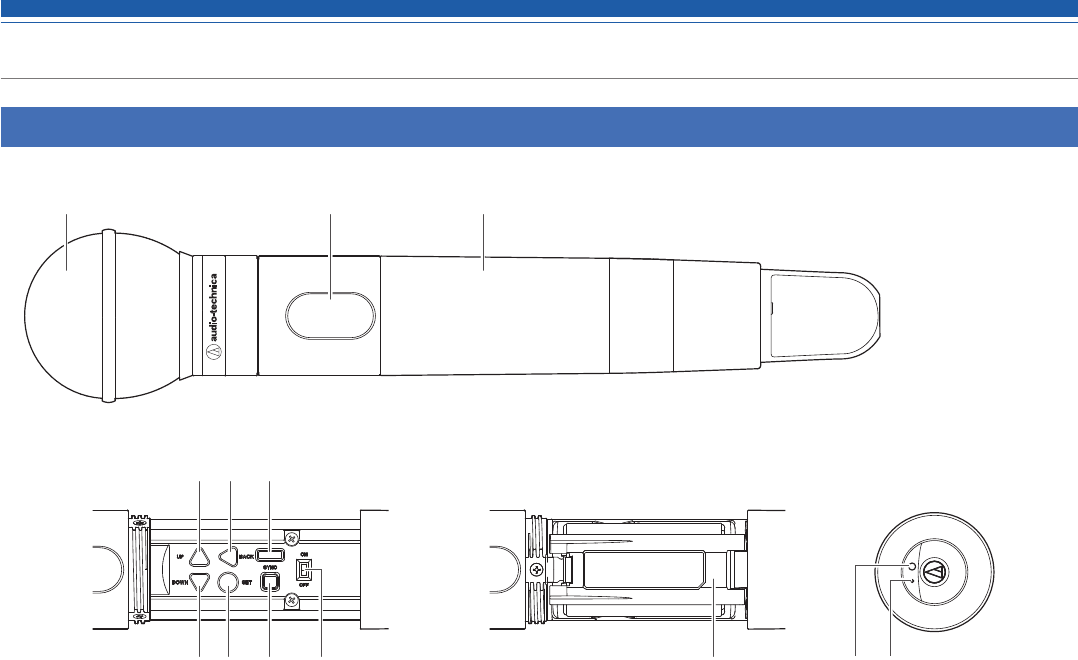
ATW-T5202
❶ Interchangeable microphone capsule
❷ Display
Shows the current status.
If no buttons are pressed for a period of 30 seconds, the display
will turn off.
❸ Grip case
❹ UP button
Used for selecting various settings.
❺ BACK button
Press to take the display back one screen.
Returns to the Main screen when pressed and held.
❻ IR sync window
Use to IR SYNC with the receiver.
❼ DOWN button
Used for selecting various settings.
❽ SET button
Press to confirm a selection.
❾ SYNC button
Use to IR SYNC with the receiver (ATW-R5220/ATW-R5220DAN).
❿ Power switch
Use to turn the power on or off.
⓫ Battery cover
⓬ Function button
Press briefly to turn the screen back on if it shuts off. Press and
hold to perform preselected function.
⓭ Indicator
LED that shows the status of the transmitter.
When the power is turned ON: Solid green
When the transmitter is muted: Solid red
❸❷❶
❹ ❺ ❻
❼ ❽ ❾ ❿ ⓫ ⓬ ⓭
9
How to insert batteries
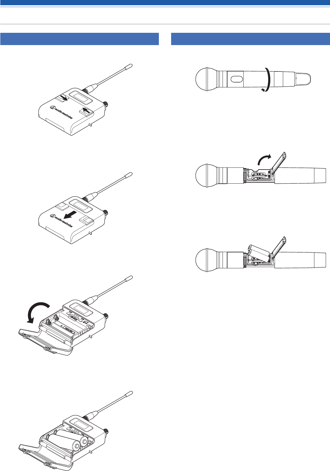
ATW-T5201
1. Slide the battery cover latches inward as shown by the arrows.
2. With the latches pressed in, slide the cover down as shown by
the arrow.
3. Open the battery cover.
4. Insert the batteries according to the plus (+) and minus (-) marks
found inside the battery compartment.
ATW-T5202
1. Rotate the grip case of the battery compartment.
2. Open the battery cover.
• Put your finger on the hook of the battery cover and pull it to open the
battery cover.
3. Insert the batteries according to the plus (+) and minus (-) marks
found inside the battery compartment.
10
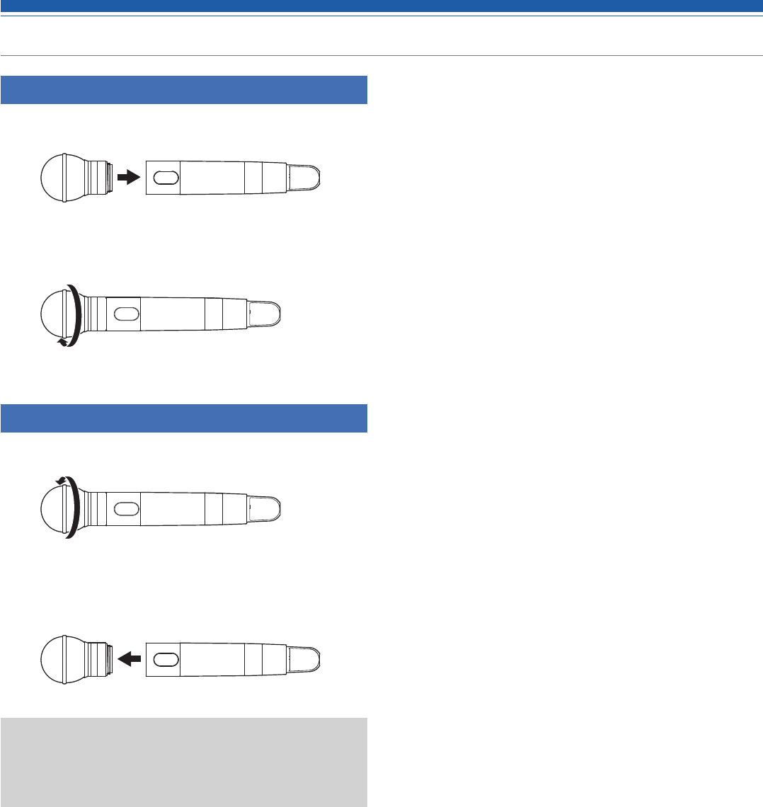
How to attach and detach the interchangeable microphone capsule (only for ATW-T5202)
How to attach
1. Attach the microphone capsule to the body of the transmitter.
2. Rotate the microphone capsule clockwise to tighten it.
How to remove
1. Rotate the microphone capsule counterclockwise to loosen it.
2. Detach the microphone capsule from the body of the
transmitter.
• Do not directly touch or scratch the connection surface.
• Be sure to turn off the power of the transmitter before attaching/
detaching the microphone capsule.
• Do not forcibly attach the microphone capsule. Doing so may damage
the transmitter or microphone capsule.
11
How to read the display
ATW-R5220/ATW-R5220DAN
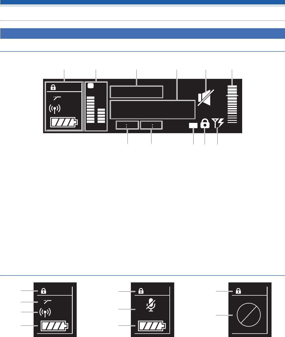
Main screen
❶ Transmitter information display area
Information on the connected transmitter is displayed. Refer to
"Transmitter information display area" (p. 10) for screen display.
❷ RF level indicator
Displays the strength of RF reception for antennas A & B.
❸ Name display
Displays the specified name.
❹ Frequency indicator
Displays the set frequency.
❺ Receiver mute indicator
A speaker icon with a slash through it is displayed when the
receiver is muted.
❻ AF level indicator
Displays the strength of the received audio signal.
❼ Group indicator
❽ Channel indicator
❾ Backup frequency indicator
"BU" icon is displayed when the backup frequency mode is ON.
❿ Lock status indicator
⓫ Antenna input power indicator
Icon is displayed when the antenna power supply is ON.
Transmitter information display area
TX
HPF
30mW
❶
❷
❸
❹
TX
MUTE
❶
❺
❹
TX
❶
❻
Normal Muted Non-communication
❶Lock status indicator
❷High-pass filter indicator
❸RF transmission output indicator
❹Battery level indicator
❺Transmitter mute indicator
A microphone with a slash through it is displayed when the
transmitter is muted.
❻Transmitter non-communication indicator
TX
HPF
B
RF AF
BU
0
000.000
VOCAL1
MHz
A
30mW
Gr 06 Ch 12
❷ ❸ ❹ ❺ ❻
❼ ❽ ❿❾ ⓫
❶
12
How to read the display
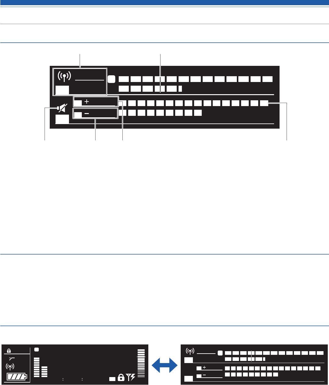
Level meter screen
Minimum hold function
If you press the BACK button on the level meter screen, the minimum hold function turns on and its marker is displayed.
• The marker indicates the lowest level of RF signal received from the transmitter.
• The marker does not move if the input RF level is higher than the marker position.
• If the RF level input is lower than the marker position, the marker moves in tandem with the RF level.
• To reset the marker position, press the BACK button again.
Switching between screens
The screen is switched every time the function button 1 is pressed.
B
RF
TX
AF
A
30mW
TX-RF PWR -92
-40 -30 -24 -18 -15 -12 -10 -8 -6 -4 -2 0+2 +4 +6 dBu
-86 -80 -74 dBm
RX
12 dB
10 dB
OL
TX
HPF
B
RF AF
BU
0
000.000
VOCAL1
MHz
A
30mW
Gr 06 Ch 12
Main screen
B
RF
TX
AF
A
30mW
TX-RF PWR -92
-40 -30 -24 -18 -15 -12 -10 -8 -6 -4 -2 0+2 +4 +6 dBu
-86 -80 -74 dBm
RX
12 dB
10 dB
OL
Level meter screen
❶ RF transmission output indicator (transmitter)
❷ Marker (when the minimum hold function is on)
Shows the minimum level at which the RF is held.
❸ Mute indicator
A speaker icon with a slash through it is displayed when
transmitter is muted.
❹ Audio output indicator (receiver)
❺ Gain indicator (transmitter)
❻ Overload (excessive input) indicator
❶❷
❸ ❹ ❺ ❻
13
How to read the display
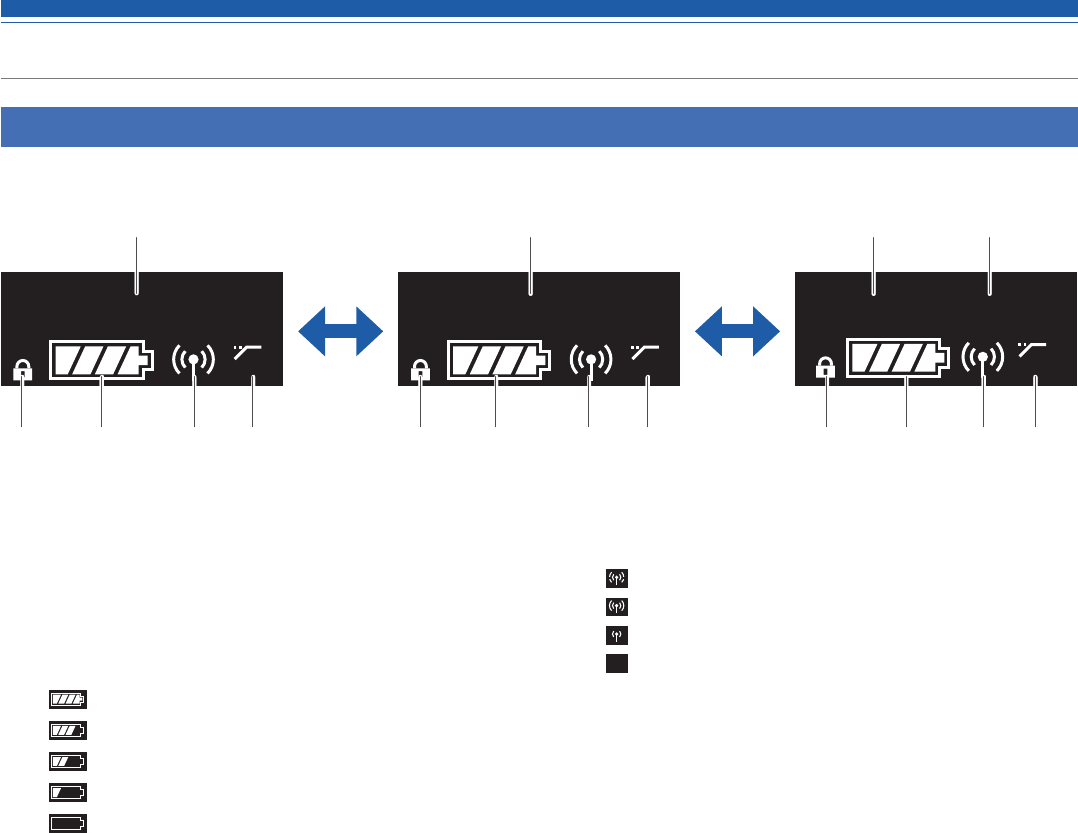
ATW-T5201/ATW-T5202
The main screen is displayed when the power is switched on. If you press the UP/Down button on the main screen, the screen display is switched.
HPF
000.000
MHz
VOCAL1
HPF
HPF
Gr
:
02 Ch
:
05
❶ Frequency indicator
Displays the set frequency.
❷ Lock status indicator
❸ Battery level indicator
: 75% or more battery power remaining.
: 50 to 75% battery power remaining.
: 25 to 50% battery power remaining.
: 25% or less battery power remaining.
(Flicker): Replace the batteries.
❹ RF transmission output indicator
:RF Power High (50mW)
:RF Power Mid (10mW)
:RF Power Low (2mW)
RF
OFF :RF Power Off
❺ High-pass filter indicator
❻ Name display
Displays the specified name.
❼ Group indicator
❽ Channel indicator
❶
❷ ❷❸ ❸❸❹ ❹❹❺ ❺
❻ ❼ ❽
❷ ❺
14
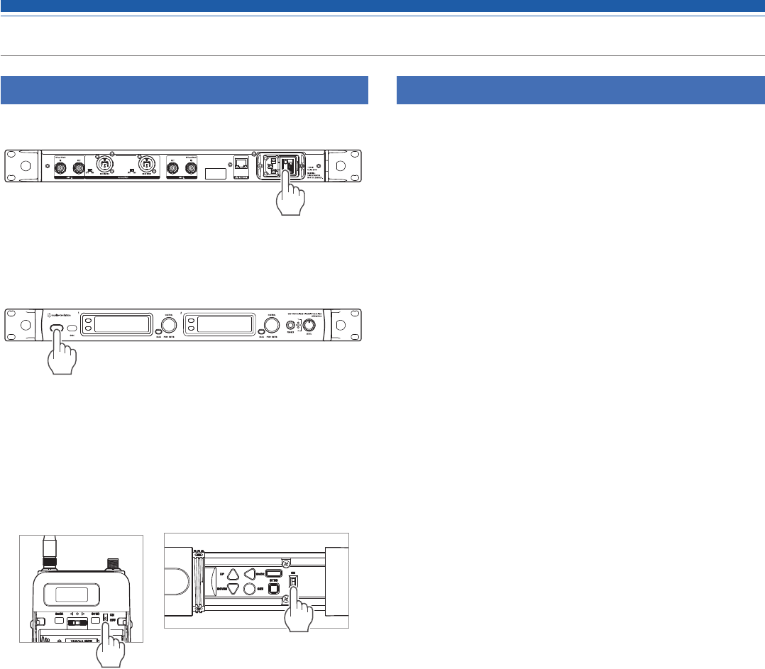
How to operate
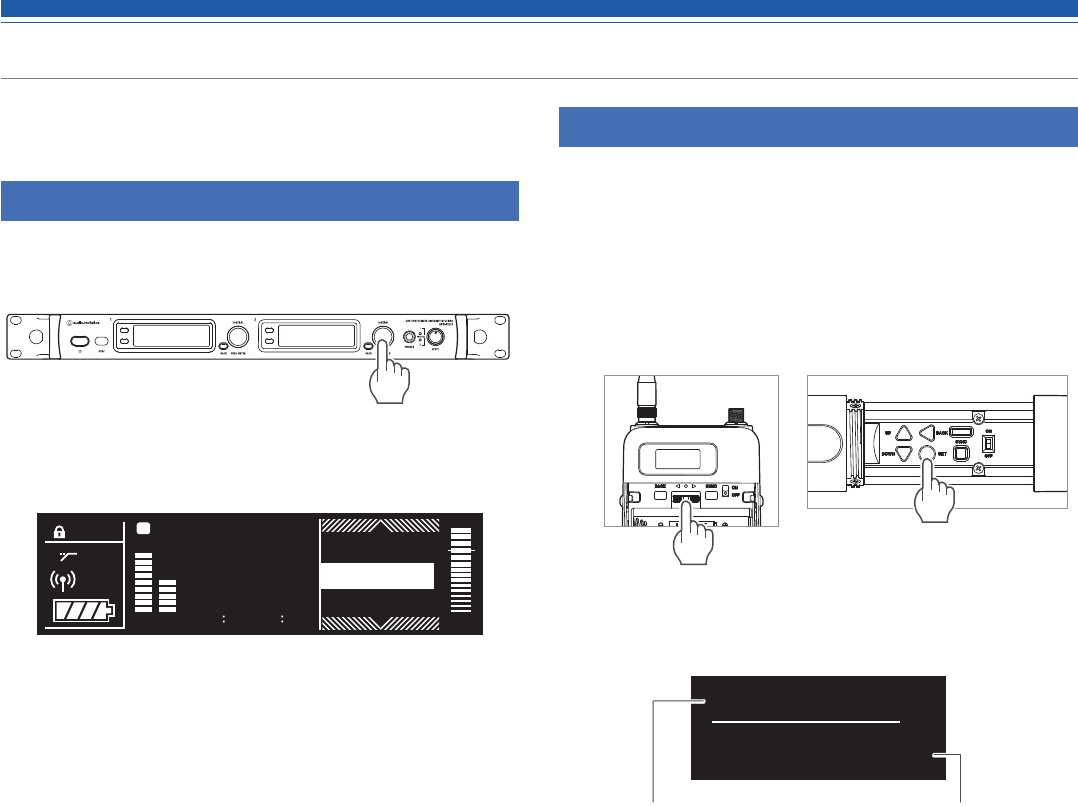
Basic operation
1. Turn on the main power button of the receiver
(ATW-R5220/ATW-R5220DAN).
2. Turn on the power button of the receiver
(ATW-R5330/ATW-R5220DAN).
• The display lights and the main screen is displayed.
3. Set the operating frequency.
4. Turn on the power switch of the transmitter
(ATW-T5201/ATW-T5202).
• The indicator lights and the display shows the main screen.
ATW-T5201 ATW-T5202
5. Set the transmission frequency.
6. Check the RF level indicator on the receiver.
• Check that antenna A or B lights up.
7. Speak into the microphone.
• Make sure the AF level indicator lights up on the receiver.
Using SYNC shortcut
You can easily move to the setting screen that you can set the settings
of the receiver with SYNC shortcut.
1. Press and hold (for approximately 2 seconds) the control dial on
the main screen.
2. “TX SYNC” setting screen is displayed.
• Refer to "Using IR SYNC" (p.p. 17) for subsequent steps.
15
Settings
Various settings can be made from the menu screen shown on the
display.
ATW-R5220/ATW-R5220DAN
1. Press the control dial.
• The main menu screen appears.
2. Turn the control dial to select the item you wish to set.
3. Press the control dial to open the settings menu of the selected
item.
• Press the BACK button to go back one screen.
• To cancel partway through making a setting, press the BACK button.
• While on the settings screen, the display will return to the main screen if
approximately 60 seconds pass without a button or the control dial being
used.
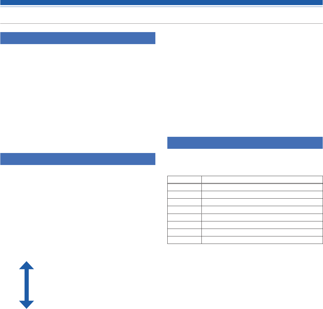
ATW-T5201/ATW-T5202
The transmitter's (ATW-T5201/ATW-T5202) UP/DOWN button operation
is explained below. In this user manual, the text is indicated as the
button operation.
ATW-T5201: Slide to the UP/DOWN position.
ATW-T5202: Press the UP/DOWN button.
1. Press the SET button.
• The menu screen appears.
ATW-T5201 ATW-T5202
2. Press the UP/DOWN button to select the item you wish to set.
.000
MHz
000
FREQUENCY
Selected
menu item
Current setting value
3. Press the SET button to display the settings screen for the
selected item.
• Press the BACK button to go back one screen.
• To cancel partway through making a setting, press the BACK button.
• While on the settings screen, the display will return to the main screen if
approximately 30 seconds pass without a button or the control dial being
used.
TX
HPF
B
RF AF
BU
0
000.000
VOCAL1
MHz
A
30mW
Gr 06 Ch 12
NAME
UTILITIES
FREQUENCY

16
Setting ATW-R5220/ATW-R5220DAN
List of setting items
FREQUENCY MANUAL Set the operating frequency.
Gr/Ch
NAME Set the channel name.
AUDIO Set the audio output level.
SCAN Scan for open channels.
TX SYNC Set transmitters via IR SYNC.
SQUELCH AUTO Set the squelch level.
MANUAL
UTILITIES LOCK Set this function to prevent the
receiver settings from being changed.
ANT PWR Set whether to turn power on or off
to the antenna input terminals.
Gr/Ch Edit the groups/channels 01 to 10.
BACKUP
FREQ
Set the backup frequency.
AF METER Switch the level meter on the main
screen between receiver and
transmitter.
BRIGHTNESS
Set the display brightness.
ACCESS Set the user access level.
RESET This returns the receiver settings to
their factory defaults.
VERSION This function displays product
information such as the version of the
receiver.
NETWORK DEVICE ID Set the receiver's ID No.
IP SETTING Set the IP.
REMOTE
CTRL
Set the remote control.
SYSLOG Set whether to send the log message
to the Syslog server.
DISCOVERY Set automatic detection by the
application.
NTP Set the NTP (Network Time Protocol).
MAC
ADDRESS
Display the MAC address.
TOOLS WALK TEST Record for 90 sec. the RF level being
received.
MONITOR
MODE
This mode will enable monitoring
with headphones only. (The audio
OUT and DANTE OUT will be muted.)
DANTE* INFO Display the device name and channel
label.
IP SETTING Set the DANTE's IP.
MAC
ADDRESS
Display the MAC address.
VERSION This function displays product
information such as the version of the
receiver.
* ATW-R5220DAN only
Setting the operating frequency
Manual setting
1. From the menu screen, turn the control dial, select
[FREQUENCY] and then press the control dial.
2. Select [MANUAL] and press the control dial.
3. Turn the control dial to set the first 3 digits. When finished
setting them, press the control dial.
4. Turn the control dial to set the last 3 digits. When finished
setting them, press the control dial.
• The setting is complete.
Setting by group/channel
1. From the menu screen, turn the control dial, select
[FREQUENCY] and then press the control dial.
2. Select [Gr/Ch] and press the control dial.
3. Turn the control dial to set the group. When finished setting it,
press the control dial.
4. Turn the control dial to set the channel. When finished setting it,
press the control dial.
• The setting is complete.
Setting the channel (receiver) name
The following characters can be entered:
• The maximum number of characters that can be entered is 8.
Alphabetic (uppercase
letters)
Numeric
Symbols (+, −, #, &, period) Space
1. From the menu screen, turn the control dial, select [NAME] and
then press the control dial.
2. Turn the control dial, select the desired character and then press
the control dial.
• The character is input and the cursor moves.
3. Repeat the operation in Step 2 to enter all characters.
4. Turn the control dial, select [End] and then press the control
dial.
• The setting is complete.
17
Setting ATW-R5220/ATW-R5220DAN
Setting the audio output level
1. From the menu screen, turn the control dial, select [AUDIO] and
then press the control dial.
2. Turn the control dial to set the audio output level.
• The level changes 2dB +/- each time you turn the control dial.
• It can be set from -60 to 0dB.
3. Press the control dial.
• The setting is complete.
Scanning for open channels
Scan for unused channels in the current environment for use.
1. From the menu screen, turn the control dial, select [SCAN] and
then press the control dial.
2. Turn the control dial to select the group you want to scan. After
selecting a group, press the control dial.
• Selecting "ALL" will scan all the groups.
3. Turn the control dial to select the preferred threshold. selecting
the threshold, press the control dial.
• You can select [Normal], [High] or [Low] sensitivity.
High: Prioritize the number of channels.
Normal
Low: Prioritize stable operation.
• Scan starts.
Selecting [ALL]:
4. Confirm the scan result, select the group and then press the
control dial.
5. Select the channel selection method, and them press the control
dial.
• When selecting [Manual] and pressing the control dial, available channels
and frequencies are shown in a list. Turn the control dial, select an
available channel and then press the control dial. The setting is complete.
• When selecting [Find Best] and pressing the control dial, the optimum
channel and frequency are shown. Turn the control dial, select [Set] and
then press the control dial. The setting is complete.
Selecting the group you want to scan:
4. Confirm the scan result by selecting [OK] and then pressing the
control dial.
• If you want to scan over again, select [Retry].
5. Select the channel selection method, and them press the control
dial.
• When selecting [Manual] and pressing the control dial, available channels
and frequencies are shown in a list. Turn the control dial, select an
available channel and then press the control dial. The setting is complete.
• When selecting [Find Best] and pressing the control dial, the optimum
channel and frequency are shown. Turn the control dial, select [Set] and
then press the control dial. The setting is complete.
Setting transmitters via IR SYNC
This function allows you to make transmitter settings on the receiver
and then automatically configure the transmitter via IR SYNC. The
following are the available settings and setting values:
Settings Setting values
Freq Current setting value, NoChange
Name Current setting value, NoChange
RF Pwr Low:2mW, Mid:10mW, High:50mW, NoChange
Gain -10 to +20dB, NoChange
Sens.* 0, +10dB, NoChange
Lock Lock, Unlock, NoChange
Batt Alkaline, Ni-MH, NoChange
HPF OFF, ON, NoChange
* ATW-T5201 only
1. From the menu screen, turn the control dial, select [TX SYNC]
and then press the control dial.
2. Turn the control dial to select a setting you would like to sync to
the transmitter and then press the control dial.
3. Turn the control dial to select the setting value and then press
the control dial.
4. Repeat Steps 2 and 3 for each setting you would like to sync to
the transmitter.
5. Turn the control dial, select [SYNC START] and then press the
control dial.
• Communication function is in standby. Refer to "Using IR SYNC" (p. 28)
for subsequent steps.

18
Setting ATW-R5220/TW-R5220DAN
Setting the squelch level
Setting automatically
1. From the menu screen, turn the control dial, select [SQUELCH]
and then press the control dial.
2. Turn the control dial, select [AUTO] and then press the control
dial.
3. Turn the control dial, select [Normal], [High] or [Low] and then
press the control dial.
• You can select one from [Normal], [High] or [Low].
High: Prioritize the sound/voice quality.
Normal
Low: Prioritize the available range.
• Scan starts.
• If an error message is displayed, change the operating frequency. The
error indicates that the current frequency is already in use or that there is
excessive noise.
4. Scan starts. Press the control dial.
• The setting is complete.
Setting manually
1. From the menu screen, turn the control dial, select [SQUELCH]
and then press the control dial.
2. Turn the control dial, select [MANUAL] and then press the
control dial.
3. Turn the control dial to select the value you wish to set.
• The meter indicates the RF level.
• It can be set from levels 1 to 16.
• While the available range of the transmitter becomes wider as the
squelch level is lower, there may be cases when noises occur under the
influence of other radio waves. While the available range of the
transmitter becomes narrower as the squelch level is made higher, noises
are less likely to occur due to the less influence of other radio waves.
4. Press the control dial.
• The setting is complete.
Setting the system-related functions
Setting the lock
Set this function to prevent the receiver settings from being changed.
• The default setting is [Unlock].
1. From the menu screen, turn the control dial, select [UTILITIES]
and then press the control dial.
2. Turn the control dial, select [LOCK] and then press the control
dial.
3. Turn the control dial to select [Lock] or [Unlock], and then press
the control dial.
• The setting is complete.
Setting the antenna power
Set whether to turn power on or off to the antenna input terminals.
• The default setting is [OFF].
• If set to [ON], power is supplied to both antennas A and B.
1. From the menu screen, turn the control dial, select [UTILITIES]
and then press the control dial.
2. Turn the control dial, select [ANT PWR] and then press the
control dial.
3. Turn the control dial, select [ON] or [OFF] and then press the
control dial.
• The setting is complete.

19
Setting ATW-R5220/ATW-R5220DAN
Setting group/channnel editing
Setting group/channel
Groups/Channels 01 to 10 can be edited.
1. From the menu screen, turn the control dial, select [UTILITIES]
and then press the control dial.
2. Turn the control dial, select [Gr/Ch EDIT] and then press the
control dial.
3. Turn the control dial, select [EDIT] and then press the control
dial.
4. Turn the control dial, select a channel and then press the control
dial.
5. Turn the control dial, select [ON] or [OFF] and then press the
control dial.
• If you select [OFF], the group can not be used.
6. Turn the control dial, select a channel and then press the control
dial.
7. Turn the control dial, select [EDIT] and then press the control
dial.
• By pressing [SET], you can set the frequency of the selected channel.
• If you press [RESET], the frequency of the selected channel becomes
blank.
8. After setting all channels, turn the control dial, select [Sync] or
[Save] and then press the control dial.
• If you press [Save], the setting is completed.
• If you press [Sync], the screen turns to an IR SYNC standby screen. Refer
to "Using IR SYNC" (p. 28) for subsequent steps.
Syncing the Group/Channel
The Groups/Channels that have been set with [EDIT] can be set to the
transmitter in groups with IR SYNC.
1. From the menu screen, turn the control dial, select [UTILITIES]
and then press the control dial.
2. Turn the control dial, select [Gr/Ch EDIT] and then press the
control dial.
3. Turn the control dial, select [Gr/Ch SYNC] and then press the
control dial.
4. Turn the control dial to select group and then press the control
dial.
• The screen turns to an IR SYNC standby screen. Refer to "Using IR
SYNC" (p. 28) for subsequent steps.
Setting the backup frequency mode
If you set the backup frequency in advance, you can switch the
frequency of the transmitter and receiver with the transmitter. It is
convenient to set this function when you want to switch the frequency
easily.
• The default setting is [OFF].
1. From the menu screen, turn the control dial, select [UTILITIES]
and then press the control dial.
2. Turn the control dial, select [BACKUP FREQ] and then press the
control dial.
3. Turn the control dial, select [ON] and then press the control dial.
4. Turn the control dial, select [Manual] or [Gr/Ch] and then press
the control dial.
• If you select [Manual], you can set the frequency.
• If you select [Gr/Ch], you can set the group/channel.
5. After setting each item, turn the control dial, select [Set] or
[Sync] and then press the control dial.
• If you press [SET], the setting is completed but you must still sync the
setting with the transmitter or set the backup frequency manually on the
transmitter in order to use the backup frequency.
• If you press [Sync], the screen turns to an IR SYNC standby screen. Refer
to "Using IR SYNC" (p. 28) for subsequent steps.

20
Setting ATW-R5220/ATW-R5220DAN
Setting the AF level meter on the main screen
Switch the AF level meter on the main screen between [Receiver (Rx)]
and [Transmitter (TX)].
• The default setting is [RX].
1. From the menu screen, turn the control dial, select [UTILITIES]
and then press the control dial.
2. Turn the control dial, select [AF METER] and then press the
control dial.
3. Turn the control dial, select [RX] or [TX] and then press the
control dial.
• The setting is complete.
Setting the display brightness
The default setting is [High].
1. From the menu screen, turn the control dial, select [UTILITIES]
and then press the control dial.
2. Turn the control dial, select [BRIGHTNESS] and then press the
control dial.
3. Turn the control dial, select [High] or [Low] and then press the
control dial.
• The setting is complete.
Setting the user access level
Set the user access level.
• The default setting is [Free Tuning].
1. From the menu screen, turn the control dial, select [UTILITIES]
and then press the control dial.
2. Turn the control dial, select [ACCESS] and then press the control
dial.
3. Turn the control dial, select [Free Tuning] or [Group Only] and
then press the control dial.
Free Tuning No limit
Group Only Selection of frequency can be made only
from group.
• The setting is complete.
Resetting
This returns the receiver settings to their factory defaults.
1. From the menu screen, turn the control dial, select [UTILITIES]
and then press the control dial.
2. Turn the control dial, select [RESET] and then press the control
dial.
3. Turn the control dial, select [Yes] and then press the control dial.
4. After the confirmation screen is displayed, turn the control dial
again to select [Yes] and then press the control dial.
• Reset starts.
Checking the receiver information
This function displays product information such as the version of the
receiver.
1. From the menu screen, turn the control dial, select [UTILITIES]
and then press the control dial.
2. Turn the control dial, select [VERSION].

21
Setting ATW-R5220/ATW-R5220DAN
Setting network
By connecting the receiver and PC, you can use the dedicated app for
monitoring or controlling with the PC.
Setting the receiver's ID No.
1. From the menu screen, turn the control dial, select [NETWORK]
and then press the control dial.
2. Turn the control dial, select [DEVICE ID] and then press the
control dial.
3. Turn the control dial, select the device ID and then press the
control dial.
• The setting is complete.
Setting the IP
1. From the menu screen, turn the control dial, select [NETWORK]
and then press the control dial.
2. Turn the control dial, select [IP SETTING] and then press the
control dial.
3. Select an item you want to set and press the control dial.
IP Mode Set how to obtain IP addresses.
[Auto]: IP addresses are automatically
assigned.
[Static]: Set to use the specified static IP
addresses.
IP Address* Specify static IP addresses.
Subnet Mask* Set the subnet mask.
Gateway* Set the gateway.
*This item can be set only when [IP Mode] is set to [Static].
4. Set each item.
Setting the remote control
1. From the menu screen, turn the control dial, select [NETWORK]
and then press the control dial.
2. Turn the control dial, select [REMOTE CTRL] and then press the
control dial.
3. Select an item you want to set and press the control dial.
Port Set the receiver's ID No.
Notification Receive notifications from the receiver.
LVL Notify Set whether to include the AF and RF level
in the notification from the receiver during
remote control.
Multicast IP Set the address for multicast.
Multicast Port Set the port number for multicast.
4. Set each item.
Setting the log message
Set whether to send the log message to the Syslog server.
1. From the menu screen, turn the control dial, select [NETWORK]
and then press the control dial.
2. Turn the control dial, select [SYSLOG] and then press the control
dial.
3. Turn the control dial, select [ON] or [OFF] and then press the
control dial.
• The setting is complete.
• Syslog is a standard for transferring log messages across IP networks. It
is used for administration of computer systems and security monitoring.
Setting automatic detection by the application
1. From the menu screen, turn the control dial, select [NETWORK]
and then press the control dial.
2. Turn the control dial, select [DISCOVERY] and then press the
control dial.
3. Turn the control dial, select [ON] or [OFF] and then press the
control dial.
• The setting is complete.
Setting NTP
Set the NTP (Network Time Protocol).
1. From the menu screen, turn the control dial, select [NETWORK]
and then press the control dial.
2. Turn the control dial, select [NTP] and then press the control
dial.
3. Select an item you want to set and press the control dial.
NTP Set whether to enable or disable the NTP
(Network Time Protocol).
Server adrs Set the NTP server address.
Port Set the NTP port number.
Time Zone Set the time difference from the UTC
(Coordinated Universal Time).
DST Turn on/off the daylight saving time.
DST Start Date Set the starting date of daylight saving
time.
DST Start Time Set the starting time of daylight saving
time.
DST End Date Set the ending date of daylight saving
time.
DST End Time Set the ending time of daylight saving
time.
4. Set each item.

22
Setting ATW-R5220/TW-R5220DAN
Setting MAC address
1. From the menu screen, turn the control dial, select [NETWORK]
and then press the control dial.
2. Turn the control dial, select [MAC ADDRESS].
Using test mode
Using the walk test function
When using the walk test function, record for 90 sec. the RF level
being received.
1. From the menu screen, turn the control dial, select [TOOLS] and
then press the control dial.
2. Turn the control dial, select [WALK TEST] and then press the
control dial.
3. Select [START] and press the control dial.
• Walk test starts.
Setting monitor mode
This mode will enable monitoring with headphones only. (The audio
OUT and DANTE OUT will be muted.)
1. From the menu screen, turn the control dial, select [TOOLS] and
then press the control dial.
2. Turn the control dial, select [MONITOR MODE] and then press
the control dial.
• Monitor mode is set.
Setting DANTE
This setting is used only for ATW-R5220DAN.
Displaying the device name and channel label
1. From the menu screen, turn the control dial, select [DANTE] and
then press the control dial.
2. Turn the control dial, select [INFO].
Setting the DANTE's IP
1. From the menu screen, turn the control dial, select [DANTE] and
then press the control dial.
2. Turn the control dial, select [IP SETTING] and then press the
control dial.
3. Select an item you want to set and press the control dial.
IP Mode Set how to obtain IP addresses.
[Auto]: IP addresses are automatically
assigned.
[Static]: Set to use the specified static IP
addresses.
IP Address* Specify static IP addresses.
Subnet Mask* Set the subnet mask.
Gateway* Set the gateway.
*This item can be set only when [IP Mode] is set to [Static].
4. Set each item.
Setting MAC address
1. From the menu screen, turn the control dial, select [DANTE] and
then press the control dial.
2. Turn the control dial, select [MAC ADDRESS].
Checking the receiver information
This function displays product information such as the version of the
receiver.
1. From the menu screen, turn the control dial, select [DANTE] and
then press the control dial.
2. Turn the control dial, select [VERSION].
23
Settting ATW-T5201/ATW-T5202
List of setting items
FREQUENCY MANUAL Set the transmission frequency.
Gr/Ch
NAME Set the channel name.
GAIN Set the microphone input gain.
SENSITIVITY* Set the gain.
RF POWER Set the transmission output.
HPF Set HPF (High-Pass Filter).
LOCK Set a lock.
TOOLS Fn BUTTON Set the function allocation for
function button.
TEST TONE Output a test signal from the
transmitter.
UTILITIES BATTERY Set the type of batteries used.
LED
Set whether to constantly keep
indicator turned on or off.
ACCESS Set the user access level.
RESET This returns the transmitter settings
to their factory defaults.
VERSION It shows the version of the
transmitter.
* ATW-T5201 only
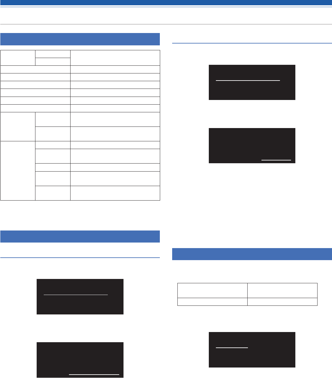
Setting the transmission frequency
Setting manually
1. From the menu screen, press the UP/DOWN button to select
[FREQUENCY], and then press the SET button.
.000
MHz
000
FREQUENCY
2. After selecting [MANUAL], press the SET button.
MANUAL
FREQUENCY
3. Press the UP/DOWN button to set the first 3 digits. After
completing the setting, press the SET button.
4. Press the UP/DOWN button to set the last 3 digits. After
completing the setting, press the SET button.
• The setting is complete.
Setting by group/channel
1. From the menu screen, press the UP/DOWN button to select
[FREQUENCY], and then press the SET button.
.000
MHz
000
FREQUENCY
2. After selecting [Gr/Ch], press the SET button.
Gr/Ch
FREQUENCY
3. Press the UP/DOWN button to set the group. After completing
the setting, press the SET button.
4. Press the UP/DOWN button to set the channel. After completing
the setting, press the SET button.
• The setting is complete.
Setting the channel (transmitter) name
The following characters can be entered:
• The maximum number of characters that can be entered is 8.
Alphabetic (uppercase
letters)
Numeric
Symbols (+, −, #, &, period) Space
1. From the menu screen, press the UP/DOWN button to select
[NAME], and then press the SET button.
NAME
2. Press the UP/DOWN to select a desired character and press the
SET button.
• The character is input and the cursor moves.
3. Repeat the operation in Step 2 to enter all characters.
• If you don't enter 8 characters, press the UP/DOWN button and select
[End] and then press the SET button.
4. After entering the 8th character, press the SET button.
• [End] is displayed.
5. Press the SET button.
• The setting is complete.

24
Settting ATW-T5201/ATW-T5202
Setting the gain
1. From the menu screen, press the UP/DOWN button to select
[GAIN], and then press the SET button.
0dB
GAIN
2. Press the UP/DOWN button to select the gain you wish to set.
• The level changes 2dB +/- each time you press the UP/DOWN button.
• It can be set from -10 to +20 dB.
3. Press the SET button.
• The setting is complete.
Setting the microphone input gain
1. From the menu screen, press the UP/DOWN button to select
[SENSITIVITY], and then press the SET button.
0dB
SENSITIVITY
2. Press the UP/DOWN button and select [0dB] or [+10dB].
3. Press the SET button.
• The setting is complete.
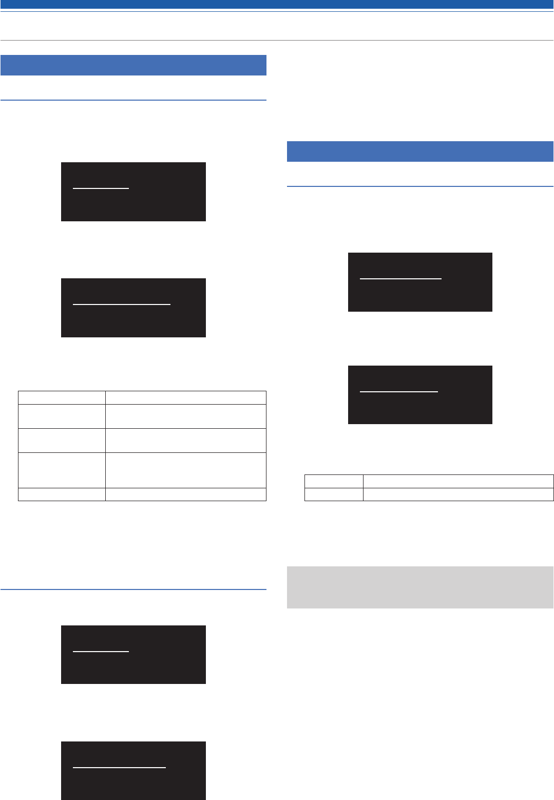
Setting the RF transmission output
1. From the menu screen, press the UP/DOWN button to select
[RF POWER], and then press the SET button.
High:50mW
RF POWER
2. Press the UP/DOWN button and select [High:50mW], [Mid:10mW],
[Low:2mW] or [Off].
3. Press the SET button.
• The setting is complete.
Setting HPF (High-Pass Filter)
1. From the menu screen, press the UP/DOWN button to select
[HPF], and then press the SET button.
O
HPF
2. Press the UP/DOWN button to select [On] or [Off].
3. Press the SET button.
• The setting is complete.
Setting lock
1. From the menu screen, press the UP/DOWN button to select
[LOCK], and then press the SET button.
Unlock
LOCK
2. Press the UP/DOWN button to select [Lock] or [Unlock].
Lock Locks transmitter buttons
Unlock Unlocks transmitter buttons
3. Press the SET button.
• The setting is complete.
25
Settting ATW-T5201/ATW-T5202
Setting the function
Setting the function for the function button
Select the function to be performed when the function button is
pressed and held
1. From the menu screen, press the UP/DOWN button to select
[TOOLS], and then press the SET button.
TOOLS
2. Press the UP/DOWN button to select [Fn BUTTON], and then
press the SET button.
Disable
Fn BUTTON
3. Press the UP/DOWN button to select the function you wish to
set.
Disable No function
Mute (only for ATW-
T5202)
Mutes the transmitter
MuteOnLock (only
for ATW-T5202)
Mutes the transmitter (even when
transmitter buttons are locked)
Bkup Freq Switches to backup frequency (When
selected, set the frequency, group, and
channel.)
RF Off Turns off RF transmission output
4. Press the SET button.
• The setting is complete.
Outputting a test signal from the transmitter
1. From the menu screen, press the UP/DOWN button to select
[TOOLS], and then press the SET button.
TOOLS
2. Press the UP/DOWN button to select TEST TONE], and then
press the SET button.
O
TEST TONE
3. Press the UP/DOWN button to select [On], and then press the
SET button.
• Outputting a test signal starts.
• While outputting a test signal, a microphone input will be muted.
Setting the system-related functions
Setting the battery type
Set the type of batteries used.
• The default setting is [Alkaline].
1. From the menu screen, press the UP/DOWN button to select
[UTILITIES], and then press the SET button.
UTILITIES
2. Press the UP/DOWN button to select [BATTERY] and press the
SET button.
Alkaline
BATTERY
3. Press the UP/DOWN button to select the battery you wish to
set.
Alkaline Select when using alkaline batteries.
NiMH Select when using nickel–metal hydride batteries.
4. Press the SET button.
• The setting is complete.
• If the appropriate setting is not made for the batteries used, the battery
power indicator will not display the correct information. Always set the
type of battery according to the batteries used.

26
Settting ATW-T5201/ATW-T5202
Setting the indicator
The indicator LED can be turned [On] or [Off].
• The default setting is [On].
1. From the menu screen, press the UP/DOWN button to select
[UTILITIES], and then press the SET button.
UTILITIES
2. Press the UP/DOWN button to select [LED] and press the SET
button.
On
LED
3. Press the UP/DOWN button to select [On] or [Off].
4. Press the SET button.
• The setting is complete.
Setting the user access level
Set the user access level.
• The default setting is [Free].
1. From the menu screen, press the UP/DOWN button to select
[UTILITIES], and then press the SET button.
UTILITIES
2. Press the UP/DOWN button to select [ACCESS] and press the SET
button.
Free
ACCESS
3. Press the UP/DOWN button to select [Free] or [Group].
Free No limit
Group Selection of frequency can be made only
from group.
4. Press the SET button.
• The setting is complete.
Resetting
This returns the transmitter settings to their factory defaults.
1. From the menu screen, press the UP/DOWN button to select
[UTILITIES], and then press the SET button.
UTILITIES
2. Press the UP/DOWN button to select [RESET] and press the SET
button.
No
RESET
3. Press the UP/DOWN button to select [Yes].
4. When the confirmation screen is shown, press the UP/DOWN
button again to select [Yes].
5. Press the SET button.
• Reset starts.
Checking the transmitter information
This function displays the firmware version for the transmitter.
1. From the menu screen, press the UP/DOWN button to select
[UTILITIES], and then press the SET button.
UTILITIES
2. Press the UP/DOWN button to select [VERSION] and press the SET
button.
• The version is shown.
000.000.000
VERSION
27
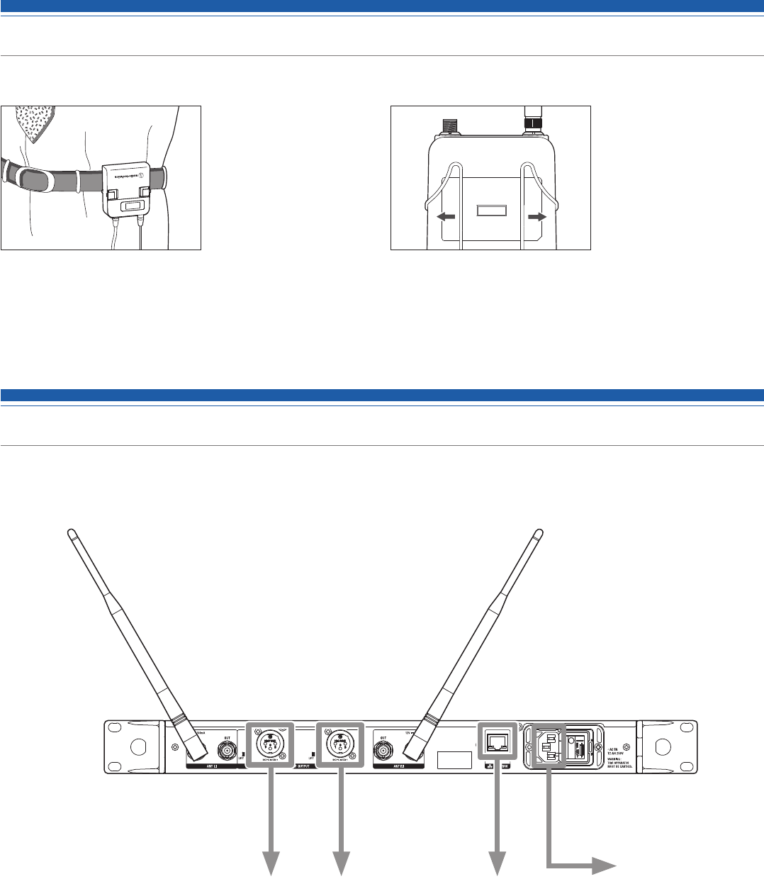
How to attach the transmitter (ATW-T5201)
The ATW-T5201 transmitter is equipped with a clip that can be used to attach the transmitter to a belt, etc.
You can reverse the direction of the input connector by
attaching the clip in the opposite direction.
Pull both sides of the clip firmly to the outside to remove
the clip from the transmitter.
Making connections (basic connections)
This is an example of connections made when using one receiver.
When connecting more than one receiver via a distributor (sold separately), refer to the distributor's user manual.
Whip antenna Whip antenna
Power cable
To computer or
DANTE device
Mixer input Mixer input
28
Using IR SYNC
This function allows you to make settings on the receiver that are specified for the transmitter.
1. When IR SYNC is started as part of setting the receiver, the “Communication in standby” screen is displayed.
2. Position the IR sync windows of the receiver and transmitter so they face each other.
3. Press the SYNC button on the transmitter.
• Wait several seconds until communication is established.
4. When the SYNC is complete, the “completed” screen is displayed.
• The settings made on the receiver are automatically synced to the transmitter.
• If an error occurs in the SYNC process, an error screen opens and then the display returns to the menu screen. Check the IR SYNC windows of the receiver and
transmitter and then SYNC again.
• To cancel the SYNC process, press the BACK button on the receiver. You will be returned to the previous screen.
Achieving stable reception
Low RF signal may result if there are obstructions between receiver antennas and transmitter(s). In such a case, reposition the antennas to get
better reception. Use external antennas (sold separately) if the installation space is limited.
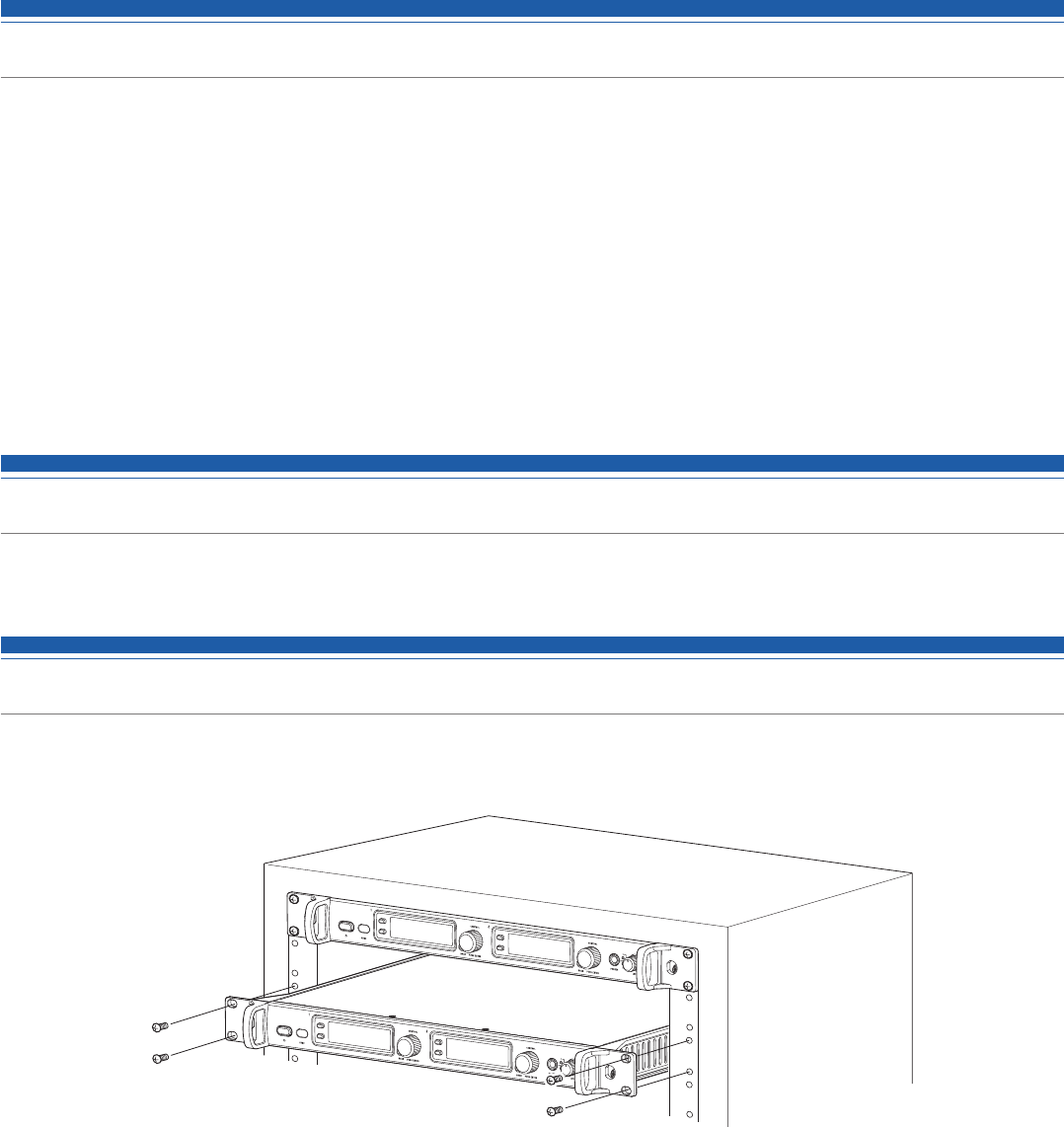
Rack-mounting the receiver
• Screws for rack-mounting the receiver are not included.
• Consider ventilation when rack-mounting to avoid heat building up in the rack.
•
29
Troubleshooting
ATW-R5220/ATW-R5220DAN
Symptoms Causes and countermeasures Reference page
The power can't be turned on. Confirm that the power cable is correctly connected. -
There is no voice output. The voice output level is low. Confirm that the transmitter/receiver channels are correct p. 15, p. 20
Confirm that the power buttons of the transmitter/receiver are not turned OFF. p. 13
Confirm that the antennas are correctly connected. -
Confirm that all connected components, such as a mixer, are correctly connected to
the receiver. -
Confirm that the audio output isn't set to the minimum level. p. 16
Confirm that the audio output level of connected components (such as a mixer) is not
minimized. -
Sound is distorted. Confirm that the audio output level isn't too high. p. 16
Confirm that the volume of any connected component isn't too high. -
There is unwanted noise. Confirm that there is no noise source, such as a fluorescent lamp or electric
component, near the receiver. -
Confirm that each transmitter is using a different frequency. -
Confirm that the output terminal of the receiver is correctly connected. p. 24
Confirm that the receiver isn't taking power from an electrical outlet that is also being
used by another noisy component. -
Confirm that there isn't any other nearby wireless system using the same frequency
band. Adjust the squelch level. p. 17
ATW-T5201/ATW-T5202
Symptoms Causes and countermeasures Reference page
The power can't be turned on. Confirm that batteries are in place. -
Confirm that batteries are not depleted. -
Confirm that batteries are inserted in the right direction. p. 8
There is no voice output. The voice output level is low. Confirm that the transmitter/receiver channels are correct p. 15, p. 20
Confirm that the power switch is not turned OFF. p. 13
Confirm that RF Power isn't OFF. p. 21
Confirm that the transmitter isn't in mute mode. p. 21
Confirm that the transmission output of the transmitter is not too low. p. 21
Confirm that the microphone or the guitar cable is not disconnected (only for ATW-
T5201). -
Confirm that the output volume of the musical instrument, such as a guitar, isn't set
at the minimum level. -
Confirm that the microphone capsule is connected properly (only for ATW-T5202). p. 9
Sound is distorted. Confirm that the gain setting of the transmitter is not too high. p. 21
There is unwanted noise. Confirm that there is no noise source, such as a fluorescent lamp, LED lamp, or
electric component, near the transmitter. -
Confirm that each transmitter is using a different frequency. -
Confirm that the transmission output setting of the transmitter is not too high. p. 21
30
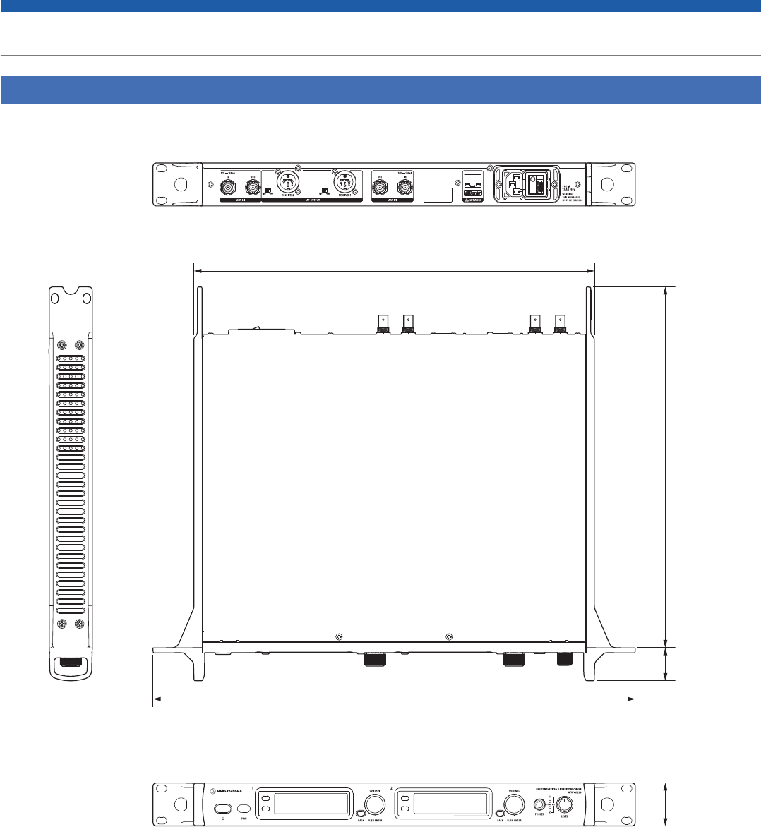
(Unit: mm)
Dimensions
ATW-R5220/ATW-R5220DAN
482.0
400.0
32.843.0 361.0
31
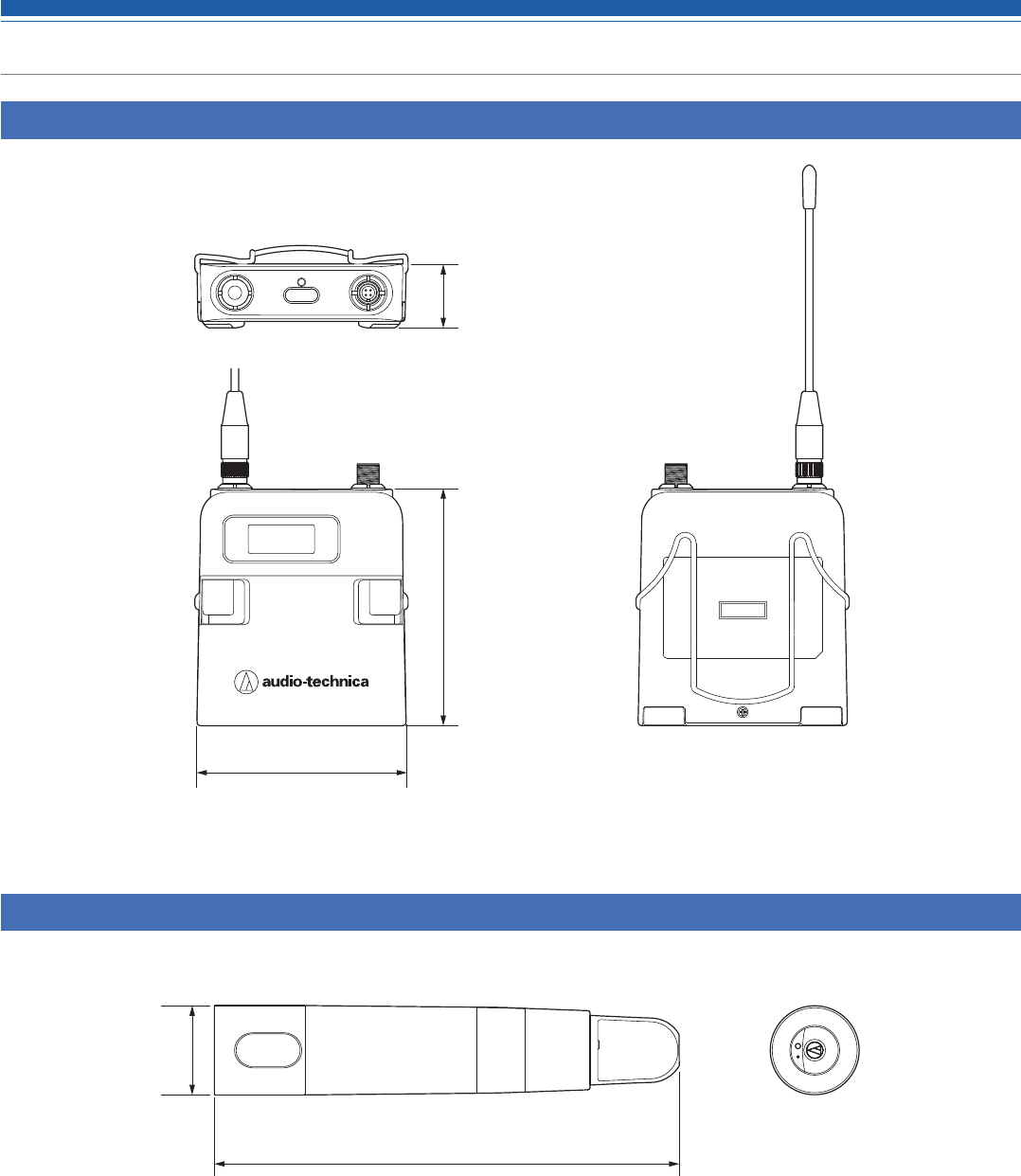
(Unit: mm)
(Unit: mm)
Dimensions
ATW-T5201
ATW-T5202
193.0
Φ
37
64.0
70.0 17.0

32
Specifications
Overall system specifications
Operating frequencies*1 Frequency range Number of frequencies
ATW-R5220
Band DG1:
Band DF1:
ATW-T5201/ATW-T5202
Band DE1:
Band EG1:
Band FE2:
470.125 to 699.875 MHz
470.125 to 607.875 MHz, 657.100 to 662.900 MHz
470.125 to 590.000 MHz
580.000 to 699.875 MHz
580.000 to 607.875 MHz, 657.100 to 662.900 MHz
9,191
5,511+233
4,796
4,796
1,116+223
Minimum frequency step 25 kHz
Modulation mode FM
Maximum deviation ATW-T5201: ±40 kHz (THD:10%)
ATW-T5202: ±40 kHz (THD:10%)
Dynamic range
ATW-T5201 Mic input: 120 dB or higher (A-weighted), typical
ATW-T5201 Inst input: 107 dB or higher (A-weighted), typical
ATW-T5202: 116 dB or higher (A-weighted), typical
Total harmonic distortion 1.0 % or less (at 1 kHz, ±17.5 kHz deviation)
Operating range*2 100 m (328')
Frequency response*3 ATW-T5201: 23 Hz to 16,300 Hz
ATW-T5202: 33 Hz to 16,300 Hz
*1 Please note that some frequency bands might not be available in your territory or could come with a limited tuning bandwidth/transmitting power due to local regulations.
*2 Open range environment with no interfering signals.
*3 Frequency response depends on attached microphone element.
ATW-R5220/ATW-R5220DAN
Receiving system True diversity
Image rejection 80 dB nominal
RF sensitivity 18 dBuV at 60 dBA S/N ratio (50 ohms termination)
Maximum output level XLR, Balanced, +18 dBV
Headphone output connector 6.3 mm (1/4") TRS Stereo
Headphone output power 180 mW, typical
Antenna input BNC-type, 50 ohms
Antenna power 12 V DC, 150 mA (combined)
Power supply 100 to 240 V AC (50/60 Hz)
Operating temperature range -5 ºC to +45 ºC (23 º F to 113 ºF)
Dimensions 482.0 mm (18.98") x 361.0 mm (14.21") x 43.0 (1.69") mm (W x D x H)
Weight (without accessories) 4.8 kg (169.3 oz)
Included accessories Rack-mount (large, small), Rack-mount screw set, Flexible UHF antenna x 2, AC adapter (country dependent)
ATW-T5201
RF output power High: 50 mW, Mid: 10 mW, Low: 2 mW (switchable), at 50 ohms
Spurious emissions Following federal and national regulations
Input connection Four pin locking connector
14
23
Pin 1: GND
Pin 3: MIC INPUT
Pin 2: INST INPUT
Pin 4: DC BIAS +5 V
High-pass (low-freq. roll-off) 80 Hz, 12 dB/octave
Batteries Two 1.5V AA, not included
Battery life* High: 7 hours, Mid: 9 hoursm Low: 10.5 hours (alkaline)
Dimensions 62 mm (2.44") × 70 mm (2.75") × 17 mm (0.67") (W × D × H)
Weight (without batteries) 92 g (3.2 oz)
Operating temperature range -5 ºC to +45 ºC (23 º F to 113 ºF)
Included accessories AT-BG3 Protective Carrying Case
* Depending on battery type, usage and environmental conditions.

33
Specifications
ATW-T5202
RF output power High: 50 mW, Mid: 10 mW, Low: 2 mW (switchable), at 50 ohms
Spurious emissions Following federal and national regulations
Microphone capsule Interchangable industry standard thread
High-pass (low-freq. roll-off) 80 Hz, 6dB/octave
Batteries Two 1.5V AA, not included
Battery life* High: 6.5 hoursm Mid: 8 hours, Low: 9.5 hours (alkaline)
Dimensions
ATW-T5202 (without capsule): 193 mm (7.60") long, 37 mm (1.46") maximum diameter
ATW-T5202/C510: 265 mm (10.43") long, 54 mm (2.13") maximum diameter
ATW-T5202/C710: 271 mm (10.67") long, 50 mm (1.97") maximum diameter
Weight (without batteries)
ATW-T3202 (without capsule): 200 g (7.1 oz)
ATW-T5202/C510: 330 g (11.6 oz)
ATW-T5202/C710: 314 g (11.1 oz)
Operating temperature range -5 ºC to +40 ºC (23 º F to 104 ºF)
Included accessories AT8456a Quiet-Flex™ stand clamp (5/8"-27 male to 3/8"-16 female threaded screw adapter)
* Depending on battery type, usage and environmental conditions.
For product improvement, the product is subject to modification without notice.
Audio-Technica Corporation
2-46-1 Nishi-naruse, Machida, Tokyo 194-8666, Japan
www.audio-technica.com
©2018 Audio-Technica Corporation
Global Support Contact: www.at-globalsupport.com ver.1 2018.08.01232417000-02-01