Audio Technica T6001S UHF SYNTHESIZED WIRELESS TRANSMITTER User Manual ATW T6001 S Manual EN 20151106
Audio-Technica Corporation UHF SYNTHESIZED WIRELESS TRANSMITTER ATW T6001 S Manual EN 20151106
User Manual
User Manual
UHF SYNTHESIZED WIRELESS
TRANSMITTER
ATW-T6001 S
Thank you for purchasing the product.
Before using the product, take time to read this user manual
thoroughly and use the product correctly. Keep this user
manual handy together with the warranty so that it is always
available for reference.

2
Features
・・・・・・・・・・・・・・・・・・・・・・ 2
Important information
・・・・・・・・・・・・・・ 3
Notes on use ・・・・・・・・・・・・・・・・・・・ 4
When using multiple wireless systems
・・・・・ 4
Part names and functions ・・・・・・・・・・・・ 5
How to insert batteries ・・・・・・・・・・・・・・ 6
About display
・・・・・・・・・・・・・・・・・・・ 7
About settings
・・・・・・・・・・・・・・・・・・・ 8
Menu screen ・・・・・・・・・・・・・・・・・・・・・・・・・・ 8
Transmission frequency setting
・・・・・・・・・・・・・・・・ 9
NAME setting ・・・・・・・・・・・・・・・・・・・・・・・・・ 9
To correct characters
・・・・・・・・・・・・・・・・・・・・・10
Transmission power setting
・・・・・・・・・・・・・・・・・10
Gain setting
・・・・・・・・・・・・・・・・・・・・・・・・・・10
Key lock setting
・・・・・・・・・・・・・・・・・・・・・・・・10
Lock code setting
・・・・・・・・・・・・・・・・・・・・・・・11
Battery setting
・・・・・・・・・・・・・・・・・・・・・・・・・11
Using the key lock function ・・・・・・・・・・・12
Setting up the key lock function
・・・・・・・・・・・・・・・12
Cancelling the key lock function ・・・・・・・・・・・・・・・ 12
About IR link
・・・・・・・・・・・・・・・・・・・12
How to attach to body
・・・・・・・・・・・・・・13
Troubleshooting
・・・・・・・・・・・・・・・・・13
Specications ・・・・・・・・・・・・・・・・・・14
Contents
● Simultaneous 31-band transmission
● IR Link feature for easy transmitter conguration
● A highly reliable, uniquely designed miniature
microphone connector
● Lever push switch for improved controllability
● UHF band transmitter for wireless systems resistant
to the effects of extraneous noise
● Great for stage use in live concerts, events, and
the like
● Employs PLL synthesizer method
● Greater dynamic range and lower noise thanks
to a double compandor (voice compression/
expansion) system (PAT.)
● Organic EL display for enhanced visibility
● Cover to prevent accidental operations
● Flexible 1/4 wavelength whip antenna with
broad operating range
Features

3
Important information
Warning:
To prevent fire or shock hazard, do not expose this apparatus to rain or
moisture.
Caution:
Do not expose this apparatus to drips or splashes.
To avoid electric shock, do not open the cabinet.
Refer servicing to qualified personnel only.
Do not expose this apparatus to excessive heat such as sunshine, fire
or the like.
Do not subject this apparatus to strong impact.
FCC Notice
Warning:
Changes or modifications not expressly approved in writing by Audio-
Technica may void the user’s authority to operate this equipment.
RF Exposure Statement:
This transmitter must not be co-located or operated in conjunction
with any other antenna or transmitter used in other systems.
No userserviceable parts inside. The circuits inside the chassis,
transmitters have been precisely adjusted for optimum performance
and compliance with federal regulations. Do not attempt to open the
chassis, transmitters. To do so will void the warranty, and may cause
improper operation.
Batteries caution
Keep batteries out of the reach of children.
Observe correct polarity as marked.
Do not expose the battery to excessive heat such as sunshine, fire or
the like.
Always consider the environment issues and follow local regulations
when disposing of batteries.
Remove depleted battery immediately.
Danger of explosion if battery is incorrectly replaced. Replace only with
the same or equivalent type.
Do not use new batteries and old one at the same time.
Do not use different batteries type or model.
Do not use a leaking battery. If battery leakage occurs, avoid contact
with skin.
If contact occurs, immediately wash thoroughly with soap and water.
If battery leakage comes into contact with your eyes, immediately flush
with water and seek medical.

4
● Be sure to read the operation manual for the connected device
before use.
● If you use the product close to an electronic device or communications
device (such as mobile phone), noise may be caused in the product.
If this happens, keep it away from such devices.
● When setting up the product, make sure there are no obstacles
between the product and receiver that will block the signal.
● If you use the product near a TV or radio antenna, noise may be
caused in the television or radio. If this happens, keep it away from
the television or radio.
● To prevent the batteries from wearing out, turn off the receiver power
after use or when the product is not in use.
● If the product is used for a long period of time, discoloration may
occur due to ultraviolet rays (especially direct sunlight) and friction.
● Any alteration or modication of this product is prohibited by law.
Also, disassembly of this precision product may result in electrical
shock, equipment damage or re. Never disassemble this product.
● If using multiple units in the same location, keep 80 cm or more
between individual transmitters and 3 m or more between
transmitters and receivers.
● When using multiple units, turn on the transmitters one by one,
making sure there is no noise.
When using multiple wireless systems
Notes on use
5
単三
LR
6
/
AA
/
単三
LR
6
/
AA
/
BACK SYNC
ON
OFF
FREQ.: 946-950 MHz
FCC ID: JF Z T6001S
BATT.: LR6, AA×2, 3 V
Audio-Technica Corp.
MA DE IN JAPAN
ATW-T60 01 S
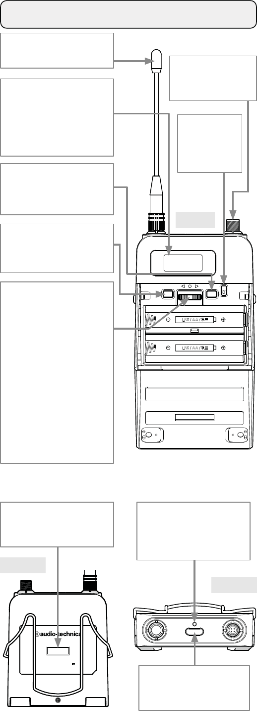
Part names and functions
Front
Transmission
antenna
Display
Shows the current status.
* If no buttons are pressed
for a period of 20 seconds,
the display will turn off.
BACK button
Returns to the previous
operation.
SYNC button
Use for IR Link with a
receiver.
Lever push switch
Used for selecting various
settings.
UP (
▲
)
Turn to the right to
change a selection.
DOWN (
▼
)
Turn to the left to
change a selection.
SET ( ●)
Press to conrm a
selection.
* For details on how to
operate, see
"About settings".
Input connector
Connect a microphone
(optional).
Power
switch
Turns the
power on/off.
Power indicator
Lights in green when the
power is on. Lights in red
when battery power is low.
Recall button
Turns the screen back on if
the screen is off.
Top
Rear
IR receiving part
This is the receiving part for
IR link.
6
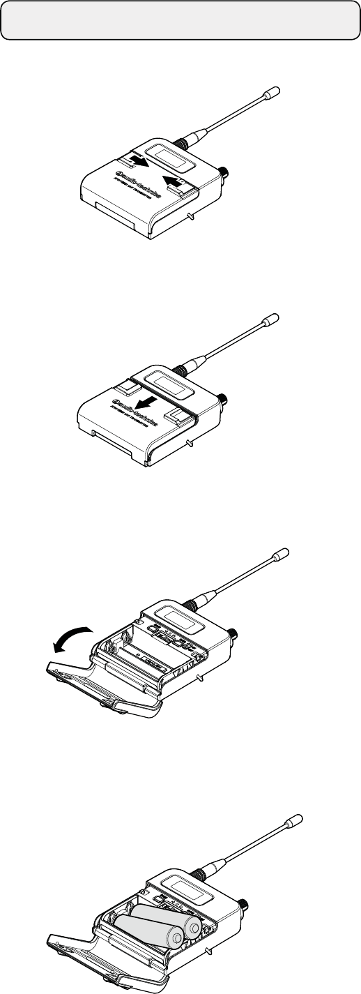
How to insert batteries
1. Slide the battery cover nob toward the inside.
2. From that position, slide the nob in the direction shown by
the arrow
3. Then, open the battery cover as shown in the diagram.
4. Insert the batteries correctly according to the plus (+) and
minus (-) marks indicated on the product.
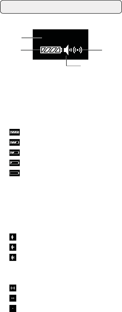
7
The main screen is displayed when the power is switched on.
946. 125MHz
①
②
③
④
① Frequency/NAME
Press UP/DOWN to switch screens.
* Only frequency displays as the default setting.
② Battery power indicator
Shows how much battery power is remaining.
: 75 % or more battery power remaining.
: 50 to 75 % battery power remaining.
: 25 to 50 % battery power remaining.
: 25 % or less battery power remaining.
: Charge the batteries.
* Use as a general guide for determining how much
battery power has been consumed.
* If there is no remaining battery power, change the batteries.
If rechargeable batteries are in use, charge them.
③ Microphone gain screen
: 0 to 6 dB
: 8 to 12 dB
: 14 to 20 dB
④ Transmission output screen
: RF Power High (50 mW)
: RF Power Mid (10 mW)
: RF Power Low (2 mW)
About display
8
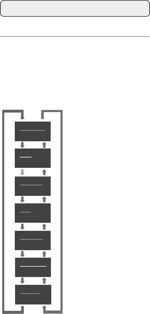
Transmission frequency setting
NAME setting
Transmission power setting
Gain setting
Key lock setting
Lock code setting
Battery setting
FREQUENCY
946. 125MHz
NAME
v
RF POWER
High
GAIN 10dB
LOCK KEY
Unlock
LOCK CODE
0000
BATTERY
Alkaline
NAME
GAIN 10dB
LOCK KEY
Unlock
BATTERY
Alkaline
LOCK CODE
0000
DOWN (◀)UP (▶)
About settings
* If there is no button operation within 10 seconds, the display
will return to the main screen.
■ Menu screen
Press the SET ( ٴ) button on the lever push switch for menu
screen mode. Moving the UP (㌣) / DOWN ( ㌢) button takes you
to the screens for the details to set in the order shown below.
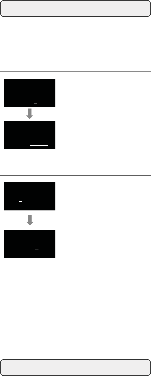
9
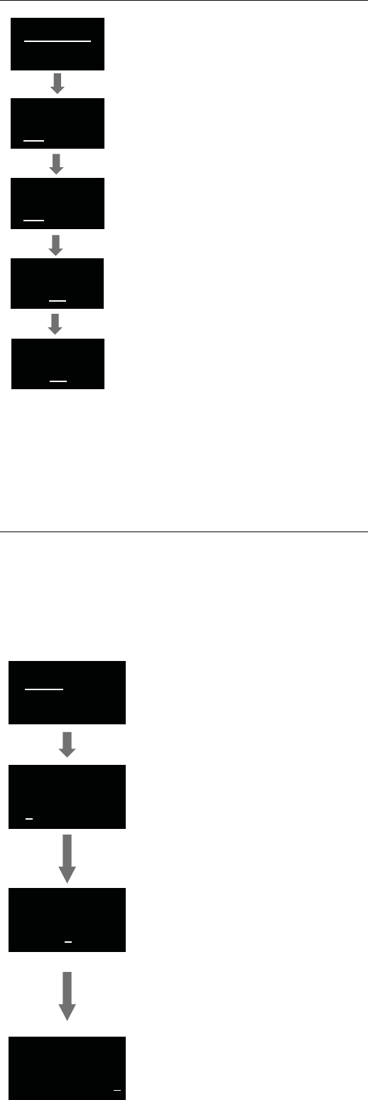
From the menu screen, use the UP/
DOWN button to select “FREQUENCY”,
and then press the SET button.
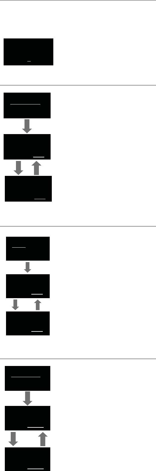
From the menu screen, use the UP/
DOWN button to select “NAME”, and then
press the SET button.
A line is displayed under the rst three
digits.
Use UP/DOWN button to select characters.
When the desired character is displayed,
press the SET button. This will conrm the
selection and move the cursor to the right.
Use the UP/DOWN button to select the
frequency.
Repeat the operation until all characters
have been entered.
An entry of 10 characters is required.
If less than 10 characters is desired, set
the entry for SPACE and press the SET
button until the cursor moves to the 10th
character position.
Use the UP/DOWN button to select the
frequency.
Press the SET button.
A line is displayed under the last three digits.
At the 10th character position, press the
SET button.
Once pressed, "STORED" is displayed and
NAME entry is complete.
Press the SET button.
“STORED” is displayed, and the
transmission frequency setting is complete.
The maximum number of characters that can be entered is 10.
The following types of characters can be entered.
・Alphabetic (52 letters/upper and lower case) ・Period
・Numeric ・Plus
・Space ・Minus
FREQUENCY
945. 000MHz
FREQUENCY
945. 000MHz
FREQUENCY
946. 000MHz
FREQUENCY
946. 000MHz
FREQUENCY
946. 125MHz
NAME
NAME
v
NAME
v o c a l
NAME
v o c a l
■ Transmission frequency setting
■ NAME setting
10
NAME
v o c a
BS
RF POWER
High
RF POWER
High
RF POWER
Low
GAIN 10dB
GAIN 10dB
GAIN 20dB
LOCK KEY
Unlock
LOCK KEY
Unlock
LOCK KEY
Lock
To correct a character after it has been entered, select "BS" with the UP/
DOWN button.
When the SET button is pressed, the last entered character is deleted
and the cursor will move one position to the left.
■ To correct characters
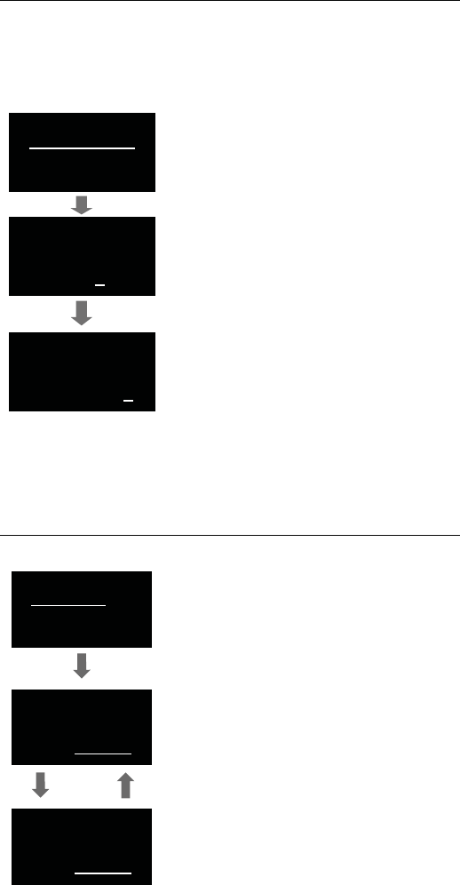
■ Transmission power setting
■ Key lock setting
■ Gain setting
From the menu screen, use the UP/
DOWN button to select “RF POWER”, and
then press the SET button.
Display the key lock status.
Unlock: Keys unlocked
Lock: Keys locked
From the menu screen, use the UP/
DOWN button to select “GAIN”, and then
press the SET button.
*Initial setting is 10 dB.
Use the UP/DOWN button to select the
transmission power.
Use UP/DOWN button to switch "High",
"Mid" and "Low".
From the menu screen, use the UP/
DOWN button to select “LOCK KEY”, and
then press the SET button.
Press the UP button to increase gain in
increments of 2 dB.
Press the DOWN button to decrease gain
in increments of 2 dB.
Press the SET button.
“STORED” is displayed, and the
transmission power setting is complete.
After selecting the key lock setting, press
the SET button.
“STORED” is displayed, and the key lock
setting is complete.
After selecting the gain, press the SET
button.
“STORED” is displayed, and the gain
setting is complete.
11
Set the type of batteries used.
From the menu screen, use the UP/
DOWN button to select “BATTERY”, and
then press the SET button.
Alkaline Selecting for alkaline
batteries
Ni-MH Selecting for nickel–metal
hydride batteries
If the appropriate setting is not made
for the battery to be used, the Battery
Power Indicator will not display the correct
information. Always set the type of battery
according to the battery to be used.
LOCK CODE
0000
LOCK CODE
0000
LOCK CODE
9999
BATTERY
Alkaline
BATTERY
Alkaline
BATTERY
Ni-MH
The lock code is a 4-digit code (from 0000 to 9999) for unlocking the keys.
If the key lock function is activated, the lock code will be required to enter
the menu screen from the main screen.
■ Lock code setting
From the menu screen, use the UP/
DOWN button to select “LOCK CODE”,
and then press the SET button.
Press the UP/DOWN button to select a
number from 0 to 9.
Once the desired number is displayed,
press the SET button to conrm the
selection.
Repeat the operation until four digits have
been entered. Once the fourth digit has
been entered, press the SET button.
Once pressed, "STORED" will be displayed
and lock code setting is complete.
After selecting the battery type, press the
SET button.
“STORED” is displayed, and the battery
setting is complete.
■ Battery setting
12
LOCK CODE
9999
LOCK KEY
Lock
0***
9 9 9 9
Using the key lock function
About IR link
The key lock function prevents entry into the menu screen to
avoid any unwanted changes to the product's settings.
When the key lock function is set at "Lock", the entry of a lock
code will be required in order to proceed to the menu screen.
The product is equipped with an IR link function. It allows you
to easily congure settings when setting with a receiver.
See the user manuals for optional receivers for instruction on
how to use IR link.
■ Setting up the key lock function
■ Cancelling the key lock function
1. Set up a lock code.
* Do not forget the 4-digit code that
you set up.
1. If the key lock function is activated,
pressing the SET button when the
main screen is on will display the lock
code entry screen.
* If there is no button operation within
10 seconds or if the BACK button is
pressed, the display will return to the
main screen.
2. Enter the 4-digit lock code which was
set up earlier. Press the UP/DOWN
button to select a desired number and
press the SET button.
Repeat the operation until all 4 numerals
have been entered.
3. Once all four numerals have been
entered, press the SET button. If the
correct lock code has been entered,
the menu screen will be displayed.
4. The key lock function can be disabled
by going to the menu screen and
setting the function at "Unlock".
2. Set the key lock function at "Lock".
* The key lock function will be activated
once you press the BACK button and
return to the main screen.
13
FREQ.: 946-950 MHz
FCC I D: JFZ T60 01S
BATT.: LR6, AA×2 , 3 V
Audio-Technica Corp.
MA DE IN JAPA N
ATW-T6001 S
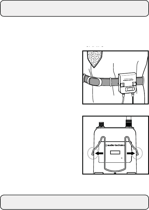
How to attach to body
The product is equipped with a clip. Use that to attach the
product to a belt, etc.
You can reverse the direction
that the input connector faces
by attaching the clip in the
opposite direction.
Pull both sides of the clip rmly
to the outside to remove the
clip from the product.
Troubleshooting
"LOW BATT" is displayed and the unit does not respond to
operation.
→ Are the batteries depleted?
Sound is distorted.
→ Is the product input level not set too high?
There is no voice output. The voice output level is low.
→ Are the frequency settings for this product or the
receiver correct?
→ Has the appropriate input level for this product been set?
→ Is the microphone properly connected?
→ Is the volume for the connected equipment completely
turned down?
There is noise.
→ Are uorescent lamps, electric appliances, and other
sources of noise kept away from the product or receiver?
→ Is the receiver not set up near a source of noise? Noise
may also be generated if power is being taken from the
same outlet as a device with much noise.