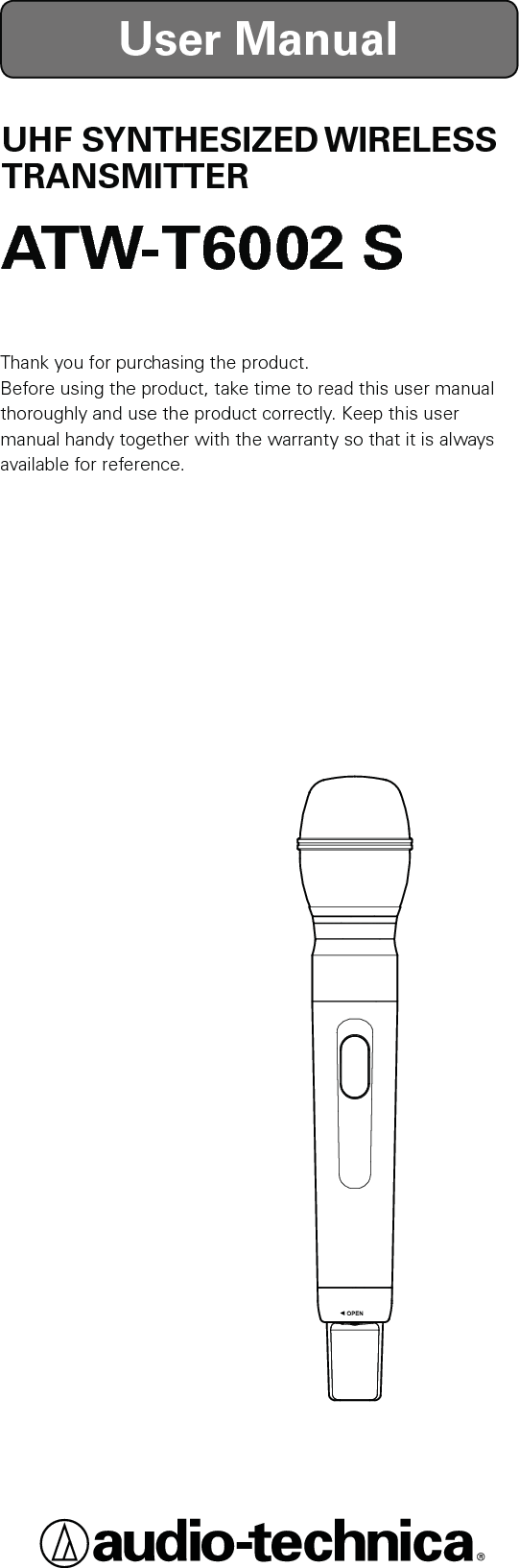
Audio Technica T6002S UHF SYNTHESIZED WIRELESS TRANSMITTER User Manual 05

Audio-Technica Corporation UHF SYNTHESIZED WIRELESS TRANSMITTER 05

User Manual

UHF SYNTHESIZED WIRELESS TRANSMITTERATW-T6002 SThank you for purchasing the product.Before using the product, take time to read this user manual thoroughly and use the product correctly. Keep this user manual handy together with the warranty so that it is always available for reference.User Manual
2● Simultaneous 31-band transmission● IR Link feature for easy transmitter conguration● UHF band transmitter for wireless systems resistant to the effects of extraneous noise● Great for stage use in live concerts, events, and the like● Employs PLL synthesizer method● Greater dynamic range and lower noise thanks to a double compandor (voice compression/expansion) system (PAT.)● Organic EL display for enhanced visibility● Specially designed high efciency antennaFeatures   ・・・・・・・・・・・・・・・・・・・・・・ 2Important information    ・・・・・・・・・・・・・・ 3Notes on use   ・・・・・・・・・・・・・・・・・・・ 4When using multiple wireless systems   ・・・・・ 4About microphone units  ・・・・・・・・・・・・・ 4Part names and functions   ・・・・・・・・・・・・ 5How to replace microphone  ・・・・・・・・・・・ 6How to insert batteries  ・・・・・・・・・・・・・・ 7About display   ・・・・・・・・・・・・・・・・・・・ 8About settings ・・・・・・・・・・・・・・・・・・・ 9  Menu screen ・・・・・・・・・・・・・・・・・・・・・・・・・・ 9  Transmission frequency setting   ・・・・・・・・・・・・・・・10  NAME setting   ・・・・・・・・・・・・・・・・・・・・・・・・・10  To correct characters   ・・・・・・・・・・・・・・・・・・・・・11  Transmission power setting  ・・・・・・・・・・・・・・・・・・11  Gain setting   ・・・・・・・・・・・・・・・・・・・・・・・・・・11  Key lock setting   ・・・・・・・・・・・・・・・・・・・・・・・・11  Lock code setting  ・・・・・・・・・・・・・・・・・・・・・・・12  Battery setting   ・・・・・・・・・・・・・・・・・・・・・・・・・12Using the key lock function   ・・・・・・・・・・・ 13  Setting up the key lock function   ・・・・・・・・・・・・・・・13  Cancelling the key lock function ・・・・・・・・・・・・・・・ 13About IR link  ・・・・・・・・・・・・・・・・・・・ 13Troubleshooting  ・・・・・・・・・・・・・・・・・ 14Specications    ・・・・・・・・・・・・・・・・・・ 14ContentsFeatures
3Warning:To prevent fire or shock hazard, do not expose this apparatus to rain or moisture.Caution:Do not expose this apparatus to drips or splashes. To avoid electric shock, do not open the cabinet.Refer servicing to qualified personnel only.Do not expose this apparatus to excessive heat such as sunshine, fire or the like.Do not subject this apparatus to strong impact.FCC NoticeWarning:Changes or modifications not expressly approved in writing by Audio-Technica may void the user’s authority to operate this equipment.RF Exposure Statement:This transmitter must not be co-located or operated in conjunctionwith any other antenna or transmitter used in other systems.No userserviceable parts inside. The circuits inside the chassis, transmitters have been precisely adjusted for optimum performance and compliance with federal regulations. Do not attempt to open the chassis, transmitters. To do so will void the warranty, and may cause improper operation.Batteries cautionKeep batteries out of the reach of children.Observe correct polarity as marked.Do not expose the battery to excessive heat such as sunshine, fire or the like.Always consider the environment issues and follow local regulations when disposing of batteries.Remove depleted battery immediately.Danger of explosion if battery is incorrectly replaced. Replace only with the same or equivalent type.Do not use new batteries and old one at the same time.Do not use different batteries type or model.Do not use a leaking battery. If battery leakage occurs, avoid contact with skin.If contact occurs, immediately wash thoroughly with soap and water.If battery leakage comes into contact with your eyes, immediately flush with water and seek medical.Important information
4● Be sure to read the operation manual for the connected device before use.● If you use the product close to an electronic device or communications device (such as mobile phone), noise may be caused in the product. If this happens, keep it away from such devices.● When setting up the product, make sure there are no obstacles between the product and receiver that will block the signal.● If you use the product near a TV or radio antenna, noise may be caused in the television or radio. If this happens, keep it away from the television or radio.● To prevent the batteries from wearing out, turn off the receiver power after use or when the product is not in use.● If the product is used for a long period of time, discoloration may occur due to ultraviolet rays (especially direct sunlight) and friction.● Any alteration or modication of this product is prohibited by law. Also, disassembly of this precision product may result in electrical shock, equipment damage or re. Never disassemble this product.● If using multiple units in the same location, keep 80 cm or more between individual transmitters and 3 m or more between transmitters and receivers.●  When using multiple units, turn on the transmitters one by one, making sure there is no noise.●ATW-C6100/HD (Dynamic microphone unit)●ATW-C4100/HD (Dynamic microphone unit)●ATW-C98/HD (Dynamic microphone unit)●ATW-C5400/HD (Back electret condenser microphone unit)●ATW-C3300/HD (Back electret condenser microphone unit)●ATW-C4200/HD (Dynamic microphone unit with mute switch)When using multiple wireless systemsAbout microphone unitsThe product can be attached to the following microphone units.  The microphone units must be purchased separately. They are not included with the product.Notes on use
5Overall DiagramControlsONSYNCBACKOFFONSYNCBACKOFFGrip caseBattery coverPush switchUsed for selecting various settings.UP (▲)Press to change a selection.DOWN (▼) Press to change a selection.SET ( ●) Press to conrm a selection.* For details on how to operate, see "About settings".BACK Returns to the previous operation.Part names and functionsDisplayShows the current status.* If no buttons are pressed for a period of 20 seconds, the display will turn off.IR receiving partThis is the receiving part for IR link.Power switchTurns the power on/off.SYNC buttonUse for IR link with a receiver.RearBottomPower indicatorLights in green when the power is on. Lights in red when battery power is low.Recall buttonTurns the screen back on if the screen is off.
6Protective capMain unitBACKOFFONSYNCAGrip caseTurn approximately a full turn and a half, and push towards the direction indicated by the arrow.Installation portionBAlign the red circles.Rotate. clickGrooveBSlide.Push the slide lock in the direction of the arrow and rotate microphone.Remove by aligning the red circles.How to replace microphone■ How to install■ How to removeMicrophone unit is sold separately.1.  Remove the protective caps from the product and the microphone.1.  Remove the microphone from the grip case by referring to "How to install" Step 2.3.  Put the protective caps on the installation portions of the microphone and product.*For the product, insert the installation portion into the grip case and put the protective cap on the installation portion.2.  Unlock the slide lock (B) by pushing it away from the product, then rotate the microphone until its red circle aligns with the product's. Pull microphone free from the product.2.  Turn the rotation lock (A) of this product's grip case approximately a full turn and a half towards    OPEN, and push the main unit free from the grip case.3.  Align the red circle on each installation portion. Rotate the microphone until its red circle aligns with the groove in the product and the microphone's slide lock (B) clicks in place.4.  Insert installation portion with microphone into the grip case and turn the rotation lock (A) to tighten.
7Main unitBACKOFFONSYNCAGrip caseTurn approximately a full turn and a half, and push towards the direction indicated by the arrow.1.  Turn the rotation lock (A) of this product's grip case approximately a full turn and a half towards    OPEN, and push the main unit free from the grip case.2.  Open the battery cover located on the back side.How to insert batteries3.  Insert the batteries correctly according to the plus (+) and minus (-) marks indicated on the product.
8②  Battery power indicator Shows how much battery power is remaining.  : 75 % or more battery power remaining.  : 50 to 75 % battery power remaining.  : 25 to 50 % battery power remaining.  : 25 % or less battery power remaining.  : Charge the batteries.* Use as a general guide for determining how much battery power has been consumed.* If there is no remaining battery power, change the batteries. If rechargeable batteries are in use, charge them.③  Microphone gain screen  : 0 to 6 dB  : 8 to 12 dB  : 14 to 20 dB × : Muted・ With no microphone unit attached・ With microphone unit's slide lock pushed up・ With ATW-C4200/HD attached and switched off④  Transmission output screen  : RF Power High (50 mW)  : RF Power Mid (10 mW)  : RF Power Low (2 mW)About displayThe main screen is displayed when the power is switched on. 946. 125MHz①②③④①  Frequency/NAME Press UP/DOWN to switch screens.  * Only frequency displays as the default setting.
9FREQUENCY946. 125MHzNAMEvRF  POWERHighGAIN 10dBLOCK  KEYUnlockLOCK  CODE0000BATTERYAlkalineNAMELOCK  KEYUnlockBATTERYAlkalineLOCK  CODE0000GAIN 10dBDOWN ( ▼)UP ( ▲)* If there is no button operation within 10 seconds, the display will return to the main screen.■ Menu screenPress the SET ( ٴ) button on the push switch for menu screen mode. Moving the UP (ٻ) / DOWN ( ٽ) button takes you to the screens for the details to set in the order shown below.About settingsTransmission frequency settingNAME settingTransmission power settingGain settingKey lock settingLock code settingBattery setting
10FREQUENCY945. 000MHzFREQUENCY945. 000MHzFREQUENCY946. 000MHzFREQUENCY946. 000MHzFREQUENCY946. 125MHzNAMENAMEvNAMEv o c a lNAMEv o c a lFrom the menu screen, use the UP/DOWN button to select “FREQUENCY”, and then press the SET button.A line is displayed under the rst three digits.Use the UP/DOWN button to select the frequency.Use the UP/DOWN button to select the frequency.Press the SET button.A line is displayed under the last three digits.Press the SET button.“STORED” is displayed, and the transmission frequency setting is complete.■ Transmission frequency settingThe maximum number of characters that can be entered is 10.The following types of characters can be entered.・Alphabetic (52 letters/upper and lower case) ・Period・Numeric ・Plus・Space ・Minus■ NAME settingFrom the menu screen, use the UP/DOWN button to select “NAME”, and then press the SET button.Use UP/DOWN button to select characters.When the desired character is displayed, press the SET button. This will conrm the selection and move the cursor to the right.Repeat the operation until all characters have been entered.An entry of 10 characters is required.If less than 10 characters is desired, set the entry for SPACE and press the SET button until the cursor moves to the 10th character position.At the 10th character position, press the SET button.Once pressed, "STORED" is displayed and NAME entry is complete.
11NAMEv o c a BSRF  POWERHighRF  POWERHighRF  POWERLowGAIN 10dBGAIN 10dBGAIN 20dBLOCK  KEYUnlockLOCK  KEYUnlockLOCK  KEY     LockTo correct a character after it has been entered, select "BS" with the UP/DOWN button.When the SET button is pressed, the last entered character is deleted and the cursor will move one position to the left.■ To correct characters■ Transmission power settingFrom the menu screen, use the UP/DOWN button to select “RF POWER”, and then press the SET button.Use the UP/DOWN button to select the transmission power.Use UP/DOWN button to switch "High", "Mid" and "Low".Press the SET button.“STORED” is displayed, and the transmission power setting is complete.■ Gain settingFrom the menu screen, use the UP/DOWN button to select “GAIN”, and then press the SET button.*Initial setting is 10 dB.Press the UP button to increase gain in increments of 2 dB.Press the DOWN button to decrease gain in increments of 2 dB.After selecting the gain, press the SET button.“STORED” is displayed, and the gain setting is complete.■ Key lock settingDisplay the key lock status.Unlock: Keys unlockedLock: Keys lockedFrom the menu screen, use the UP/DOWN button to select “LOCK KEY”, and then press the SET button.After selecting the key lock setting, press the SET button.“STORED” is displayed, and the key lock setting is complete.
12LOCK  CODE0000LOCK  CODE0000LOCK  CODE9999BATTERYAlkalineBATTERYAlkalineBATTERYNi-MHThe lock code is a 4-digit code (from 0000 to 9999) for unlocking the keys.If the key lock function is activated, the lock code will be required to enter the menu screen from the main screen.■ Lock code settingFrom the menu screen, use the UP/DOWN button to select “LOCK CODE”, and then press the SET button.Press the UP/DOWN button to select a number from 0 to 9.Once the desired number is displayed, press the SET button to conrm the selection.Repeat the operation until four digits have been entered. Once the fourth digit has been entered, press the SET button.Once pressed, "STORED" will be displayed and Lock code setting is complete.■ Battery settingSet the type of batteries used.From the menu screen, use the UP/DOWN button to select “BATTERY”, and then press the SET button.Alkaline  Selecting for alkaline     batteriesNi-MH   Selecting for nickel–metal    hydride batteriesIf the appropriate setting is not made for the battery to be used, the Battery Power Indicator will not display the correct information. Always set the type of battery according to the battery to be used.After selecting the battery type, press the SET button.“STORED” is displayed, and the battery setting is complete.
13LOCK  CODE9999LOCK  KEY     Lock0***9 9 9 9Using the key lock functionThe key lock function prevents entry into the menu screen to avoid any unwanted changes to the product's settings.When the key lock function is set at "Lock", the entry of a lock code will be required in order to proceed to the menu screen.■ Setting up the key lock function1. Set up a lock code.* Do not forget the 4-digit code that you set up.2. Set the key lock function at "Lock".* The key lock function will be activated once you press the BACK button and return to the main screen.■ Cancelling the key lock function1.  If the key lock function is activated, pressing the SET button when the main screen is on will display the lock code entry screen.* If there is no button operation within 10 seconds or if the BACK button is pressed, the display will return to the main screen.2. Enter the 4-digit lock code which was set up earlier. Press the UP/DOWN button to select a desired number and press the SET button. Repeat the operation until all 4 numerals have been entered.3. Once all four numerals have been entered, press the SET button. If the correct lock code has been entered, the menu screen will be displayed.4. The key lock function can be disabled by going to the menu screen and setting the function at "Unlock".About IR linkThe product is equipped with an IR link function. It allows you to easily congure settings when setting with a receiver.See the user manuals for optional receivers for instruction on how to use IR link.

Navigation menu