Audio MINITX MINITX Wireless Microphone Transmitter User Manual Audio 2040 User Guide
Audio Limited MINITX Wireless Microphone Transmitter Audio 2040 User Guide
Audio >
Manual

2040 User Guide
DX2040 portable true diversity receiver – page 3
miniTX miniature pocket transmitter – page 7
TX2040 pocket transmitter – page 14
HX2040 handheld transmitter – page 20
SwitchiR infrared remote control – page 26
Control-X transmitter controller – page 28

88
1
CHAPTER
1
DX2040
........................
The DX2040 true diversity receiver in the RMS2040 range
can be used with the TX2040 pocket transmitter and the
HX2040 handheld transmitter. It is also fully compatible with
the TX2020 and TX2000 UHF transmitters. All settings on the
DX2040 receiver can be read or changed via infra-red using
the SwitchiR or AudiR© for Palm™.
miniTX
........................
The miniTX transmitter is the smallest transmitter in the
Audio Ltd range. Designed as a rounded form to be very
easily concealed. All settings can be set and changed via
the infra-red port using the SwitchiR™, and the miniTX
can also be turned on and off through clothing using
the Control-X. There are two versions of the transmitter
available: one with a 4-pin Lemo connector and the other
with a 3-pin Lemo connector.
TX2040
........................
The TX2040 is a pocket transmitter that provides 32 pre-
programmed frequencies with a switching bandwidth of up
to 24MHz. The transmitter can be switched on and off, even
when it is worn beneath clothing, using the unique Control-X
handset. It is also compatible with the SwitchiR infra-red
controller, and AudiR™ application Palm PDA.
HX2040
........................
The HX2040 is a handheld transmitter designed in a classical
conical shape, designed to accept any of 14 condenser
capsules from the Schoeps™ Colette range.
The transmitter has 32 pre-programmed frequencies
with up to 24MHz switching bandwidth, and it includes a
unique infra-red remote control interface for reliable and
accessible control over settings via the SwitchiR or AudiR™
application for Palm PDAs.
Introduction
The 2040 range has been designed as a result of extensive feedback from professional sound specialists and sets a
new benchmark for radio microphone systems, with several unique features and offering benefits to appeal to sound
mixers, directors, and artists.

CHAPTER
1
88
2
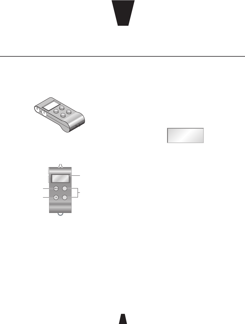
SwitchiR
........................
The SwitchiR is an infra-red remote control unit the size of
a key fob, which can be used to access all the user-settable
functions of the TX2040 and HX2040. Functions include
transmitter frequency, audio level, battery status, serial
number, and user identification.
Control-X
........................
The Control-X uses electromagnetic induction to allow the
miniTX or TX2040 transmitter to be controlled remotely, even
through clothing.
At a distance of up to 20cm (8") the Control-X can switch on
and off the transmitter, or check and display the selected
frequency, and it also provides battery check features.
RK2040
........................
The RK2040 is a compact 1U rack capable of
accommodating up to four true diversity receivers. The
RK2040 can be mains powered via an AC/DC adaptor, or can
be powered from any 10-18V DC source. A built-in RS485 PC
interface allows remote monitoring and control via Audio
Ltd’s PC-based monitoring application, Racktop.
88
3
CHAPTER
2
Controls, display and connections
........................
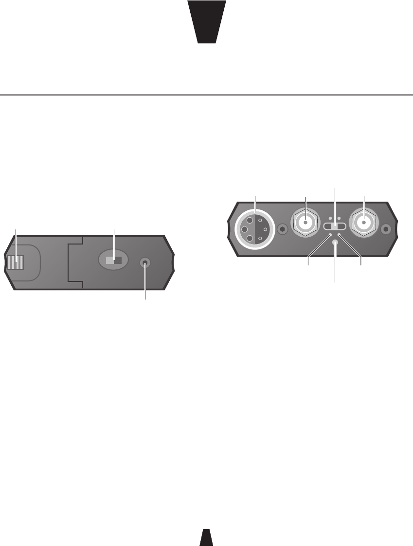
Bottom panel
Battery
compartment
Identification
plug
On/off switch
Battery compartment
Holds two 1.5v AA (LR6) type cells.
On/Off
Switches the power on or off. Additionally the output cable
includes a link which disconnects power when the Lemo
plug is removed, in which case the switch can be left on.
Identification plug
Can be fitted with one of the coloured rubber plugs supplied
with the DX2040 to identify each unit.
Top panel
Antenna A
No signal
Audio
output Antenna B
Infra-red port
TX low
battery
DX low
battery
Audio output
Provides transformer balanced microphone level and
adjustable headphone outputs.
Antenna A and Antenna B
SMA sockets to which the antennae are connected.
Indicators next to each antenna indicate which of the unit’s
two built-in receivers is active at any time.
Infra-red port
Receives commands from and transmits status information
back to the SwitchIR infra-red controller.
DX2040 Receiver
The DX2040 true diversity receiver in the RMS2040 range can be used with the TX2040 pocket transmitter and the
HX2040 handheld transmitter. It is also fully compatible with the TX2020 and TX2000 UHF transmitters. All settings on
the DX2040 receiver can be read or changed via infra-red using the SwitchiR or AudiR© for Palm™.

DX2040 Receiver
88
4
TX/DX low battery indicators
Illuminate when the unit detects low battery power in either
the TX2040 Pocket Transmitter or DX2040 Receiver. The units
should not be used when a low battery power indicator is
illuminated as poor operation may result.
Note: The low DX battery indicator does not function when
the receiver is externally powered via Audio Ltd’s cables.
This is not a fault.
No-signal indicator
Illuminated when no carrier signal is being received, such
as when the transmitter is switched off or set to an incorrect
frequency.
Setting up the DX2040
To set up the DX2040 in conjunction with a TX2040 or HX2040:
• Fit the batteries.
• Connect the A and B antennae.
• Connect the audio output cable.
• Slide the On/Off switch to the On position.
• Select the operating frequency.
• Set the output level.
• Check that one of the A and B indicators is illuminated
and that the red ‘No signal’ indicator is not illuminated.
These steps are explained below:
Fitting the batteries
To open the battery compartment, slide the release catch
towards the centre of the DX2040 and flip open the cap.
Insert two 1.5 volt AA (LR6) type batteries, negative contact
first as shown on the side of the unit, and close the cover. Do
not use excessive force.
Connecting the antennae
Connect the antennae to the SMA connectors marked
Antenna A and Antenna B. Connect the straight antenna to
one socket and the right-angled antenna to the other socket.
Selecting the operating frequency
You can check or change the operating frequency of the
DX2040 receiver via infra-red control using the SwitchiR.
To check the DX2040 frequency:
• Press MENU.
The display shows:
FREQUENCY
MHz
Fr
• Align the front of the SwitchiR with the infra-red port on
the receiver and press OK.
Optimum operating range is between 5 and 15cm.
The SwitchiR will display the
receiver frequency; for example:
FREQUENCY
Rx MHz
854.900
To change the DX2040 frequency:
• Press OK again.
The display will alternately flash between frequency and
channel number.

DX2040 Receiver
88
5
For example:
CHANNEL
01
• Press a or v to scroll through the 32 frequencies read
from the receiver until the required channel or frequency
is displayed.
For example:
CHANNEL
32
• Align the front of the SwitchiR with the infra-red port on
the receiver and press OK.
If the command was received correctly the display will show
the new frequency.
For example:
FREQUENCY
Rx MHz
857.950
Otherwise the display will show:
Error
• Repeat the above steps if an error message is displayed,
moving the SwitchiR closer to the infra-red port.
Setting the output level
The DX2040 output level is attenuated in 1dB steps over a
32dB range, allowing the receiver output to be matched to
inputs which require a lower input level. The 0dB reference
level is -25dBu.
To check the DX2040 output level:
• Press MENU.
• Press a once until
the display shows:
AF LEVEL
TxRx
AF
• Align the front of the SwitchiR with the infra-red port on
the receiver and press OK.
The display will show the current
output level setting; for example:
AF LEVEL
Rx
-07 dB
To change the receiver output level:
• Press the OK button.
The AF level display will flash.
• Press the a or v button to step between the available
output level settings until the required output level is
displayed.
For example:
AF LEVEL
TxRx
-15 dB
• Align the front of the SwitchiR with the infra-red port on
the receiver and press OK.
If the command was received correctly the new level will be
displayed.
For example:
AF LEVEL
TxRx
-15 dB
Otherwise the display will show:
Error

DX2040 Receiver
88
6
• Repeat the above steps if an error message is displayed,
moving the SwitchiR closer to the infra-red port.
Checking the DC power status
To check the status of the receiver’s DC power:
• Press MENU.
• Press a three times until
the display shows:
TxRx
BAtt
• Align the front of the SwitchiR with the infra-red port on
the receiver and press OK.
The display will
show the DC voltage:
Rx
2.7 v
If the associated transmitter is on while the DC status
is being checked the display will alternate between the
receiver’s DC status and the received transmitter DC status.
For example:
Tx
H
The transmitter status is shown as one of the following
options:
Option Description
H (high) Indicates good.
L (low) Indicates low. Replace as soon as possible.
F (failed) Transmitter will not function correctly.
External powering
Audio Ltd has a large selection of cables available for a
variety of different applications. If the DX2040 receiver is to
be externally powered, ensure that the appropriate cable is
used.
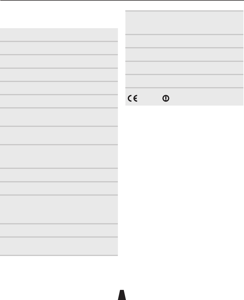
Technical specification
........................
Frequency range 470MHz–1000MHz
Number of frequencies 32 pre-programmed
Switching bandwidth Up to 24MHz
Sensitivity -98dBm for 40dB SINAD
Balanced output level -25dBu
Frequency response 50Hz to 18kHz ±1dB
THD <0.2% typical
Batteries 2 x 1.5V AA (LR6) type
Battery life > 4 hours on good alkaline batteries
Size 147 x 64 x 20mm
Weight 250g
Operating temperature
range
-20°C to +55°C
Compliant to ETS 300422 EN 300445(CE) FCC

88
7
CHAPTER
3
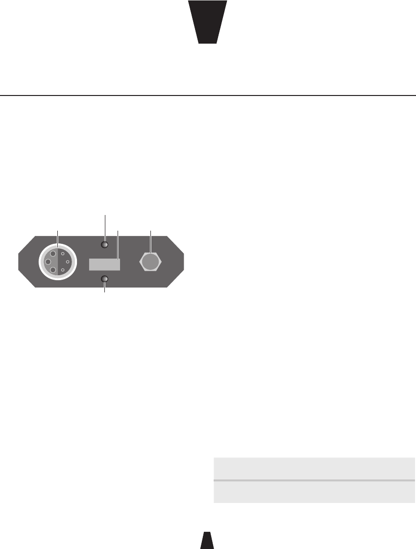
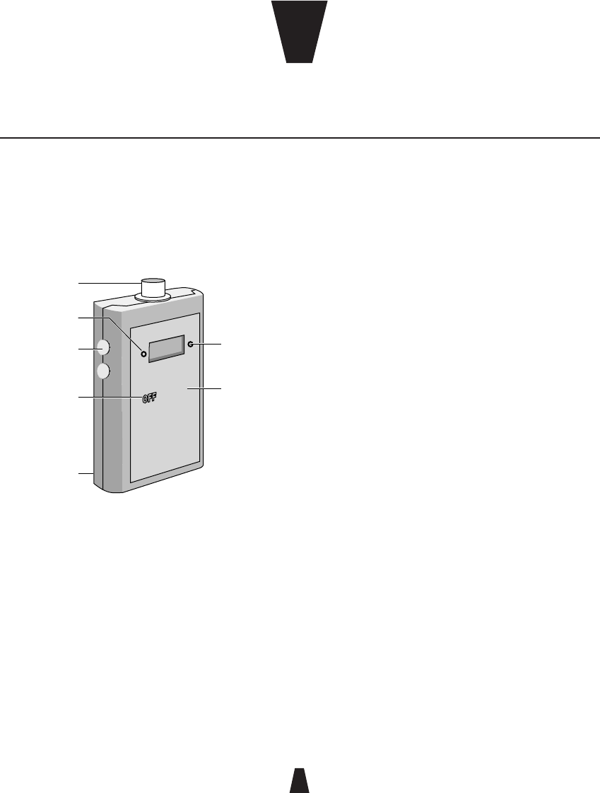
Controls, display and connections
........................
Top panel
Audio
input socket
Infra-red
port
Sleep/Low battery
(orange)
Antenna
On/Overload
(red)
Infra-red port
Receives commands from and transmits status information
back to the SwitchiR infra-red controller, or AudiR for Palm.
On/Overload indicator (red)
Flashes on momentarily to indicate an overload in the
presence of a high-level audio signal. At this point, the low
distortion limiter operates.
Sleep/Low battery indicator (orange)
Flashes every two seconds when the transmitter is in sleep
mode. Remains on when the battery is low.
Battery compartment
Holds two AAA type 1.5V alkaline or lithium batteries.
Audio input
Allows a microphone or input cable to be connected via a 4-
pin Lemo connector, or 3-pin Lemo connector on an optional
variant.
SMA antenna connector
SMA socket to which the antenna is connected.
LF cut using SwitchiR
Gives approximately 6dB LF cut at 50Hz, to assist in the
reduction of wind noise.
Gain setting using the SwitchiR
Provides eight gain options when used with standard
microphones. Position 9 gives maximum gain and each
position decreases the gain by approximately 3 to 4dB,
giving a total of 30dB of adjustment.
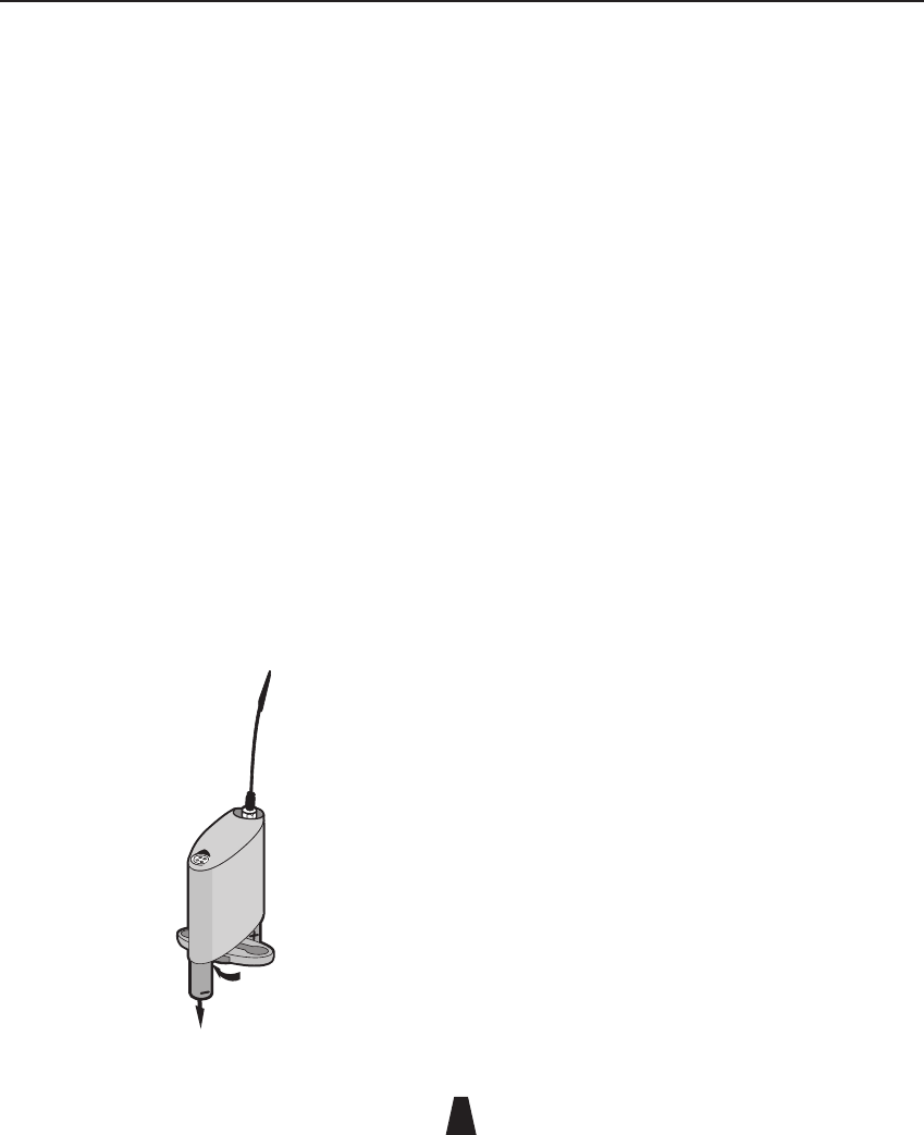
miniTX
The miniTX transmitter is the smallest transmitter in the Audio Ltd range. Designed as a rounded form to be very
easily concealed. All settings can be set and changed via the infra-red port using the SwitchiR™, and the miniTX
can also be turned on and off through clothing using the Control-X. There are two versions of the transmitter
available: one with a 4-pin Lemo connector and the other with a 3-pin Lemo connector.
miniTX Transmitter
88
8
Setting up the miniTX
........................
To set up the miniTX:
• Fit the batteries.
• Connect the antenna.
• Switch on by plugging in the microphone or input cable.
• Check or select the operating frequency.
• Check that the receiver’s no signal indicator is not
illuminated.
• Check or set the microphone gain.
• Check or set the low frequency cut filter.
• Check the battery status.
These steps are explained below:
Fitting the batteries
• Open the battery compartment by turning the battery
compartment retaining nut in an anti-clockwise direction.
• Rotate the battery cover in either direction.
• Insert two AAA (LR03) type batteries as shown in the
diagram on the miniTX cover.
• Close the battery compartment and tighten the battery
compartment retaining nut in a clockwise direction. Take
care not to over tighten.
An electronic resettable fuse protects the transmitter from
reverse powering.
Low battery indication
When the battery is low the orange LED will remain on. The
miniTX should not be used when the battery is low as poor
operation may result. A low transmitter battery indicator
is also provided on the DX2040 receiver and on the RK2040
rack.
Note: On the miniTX fitted with the 3-pin Lemo connector,
the transmitter will switch on as soon as the batteries have
been fitted to the transmitter. To maximize battery life the
miniTX should be put into sleep mode by turning the miniTX
off using the SwitchiR.
Connecting the antenna
• Connect the flexible antenna to the SMA connector.
Switching on
• Insert the microphone plug.
The red LED illuminates momentarily under the top cover to
indicate that the transmitter has been turned on.
miniTX Transmitter
88
9
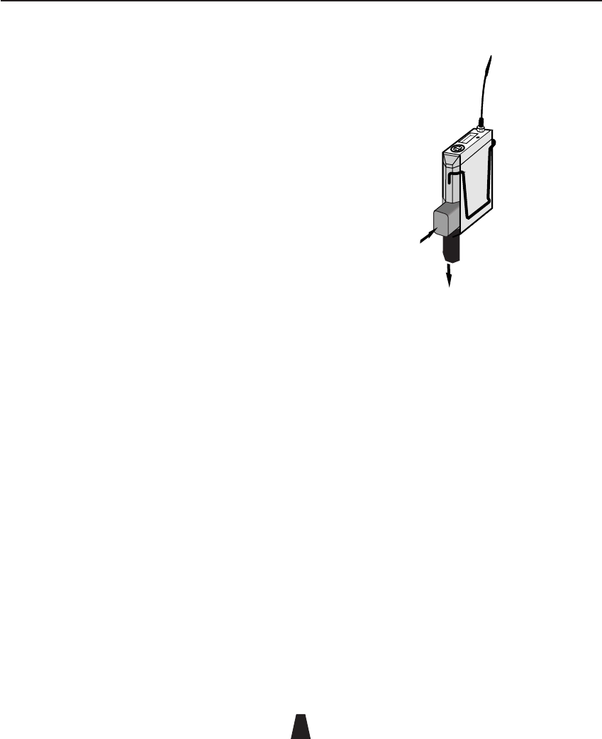
Switching off
To turn the transmitter off remove the Lemo plug, or put the
miniTX in sleep mode by switching it off using the SwitchiR.
Alternatively the miniTX can be turned off or on, even
through clothing, using the Control-X.
In sleep mode the orange LED will flash every two seconds
and the transmitter will draw very little current.
Connecting the audio input
• Connect the microphone or input cable to the four-pin
Lemo socket.
A positive microphone bias voltage is provided, enabling the
majority of modern lavalier microphones to be used with the
miniTX.
Selecting the operating frequency
You can check or change the operating frequency of the
miniTX via the infra-red control using the SwitchiR.
To check the frequency:
• Press MENU.
The display shows:
FREQUENCY
MHz
Fr
• Align the front of the SwitchiR with the infra-red port on
the miniTX and press OK.
The display shows the current
frequency; for example:
FREQUENCY
Tx MHz
854.900
To change the frequency:
• Press OK.
The display will alternately flash between showing the
frequency and channel number.
For example:
CHANNEL
01
• Press a or v to scroll through the 32 frequencies read
from the transmitter until the desired frequency or
channel is displayed.
For example:
CHANNEL
32
• Point the SwitchiR at the infra-red port on the miniTX and
press OK.
If the command was received successfully the display will
show the new set frequency.
For example:
FREQUENCY
Tx MHz
857.950
Otherwise it will show:
Error
• Repeat the above steps if an error message is displayed,
moving the SwitchiR closer to the infra-red port.
miniTX Transmitter
88
10
Setting the gain
The steps between gain settings 2-9 are approximately 3
to 4dB. Set the gain position so that the Overload indicator
does not flash on during normal operation.
To check the gain setting:
• Press MENU followed by a.
The display will indicate:
AF LEVEL
TxRx
AF
• Align the front of the SwitchiR with the infra-red port of
the miniTX and press OK.
The display will show the current
transmitter gain setting:
AF LEVEL
Tx
0
To change the gain setting:
• Press OK again.
The display will flash the level setting.
• Press a or v to step between gain settings 2-9 until the
required gain setting is displayed.
For example:
AF LEVEL
Tx
9
• Align the front of the SwitchiR with the infra-red port on
the transmitter and press OK.
If the command was received correctly the display will show
the new gain setting.
For example:
AF LEVEL
Tx
9
Otherwise the display shows:
Error
• Repeat the previous steps if an error message is
displayed, moving the SwitchiR closer to the infra-red
port.
Setting the low frequency cut filter
The LF cut filter gives an approximately 6dB cut at 50Hz to
reduce handling and wind noise.
To check the status of the low frequency cut filter:
• Press MENU.
• Press a twice until the
display shows:
Tx
LF Cut
• Align the front of the SwitchiR with the infra-red port on
the transmitter and press OK.
The current LF cut filter setting
is displayed; for example:
Tx
OFF
To change the filter setting:
• Press OK again.
The current setting will flash.
• Press a or v to toggle between ON or OFF until the
required setting is displayed.
miniTX Transmitter
88
11
• Align the front of the SwitchiR with the infra-red port on
the transmitter and press OK.
If the command was received successfully the new setting
will be displayed.
For example:
Tx
On
Otherwise the display will show:
Error
• Repeat the previous steps if an error message is
displayed, moving the SwitchiR closer to the infra-red
port.
Checking the battery status
• Press MENU.
• Press a three times until
the display shows:
TxRx
BAtt
• Align the front of the SwitchiR with the infra-red port on
the transmitter and press OK.
The display will show the
current battery status:
Tx
2.6 v
The battery level can also be checked from the receiver; see
the appropriate instructions for the receiver.
Infra-red disable
........................
You can protect the miniTX from an accidental change
of settings, such as in a live performance, by disabling
the infra-red port on the transmitter. This will prevent all
communication with the transmitter until the the battery is
disconnected and reconnected via the microphone plug.
Disabling the infra-red port
• Press MENU.
• Press v twice.
The display
will show:
TxRx
dISABLE
TxRx
Ir ?
• Align the front of the SwitchiR with the infra-red port on
the transmitter and press OK.
If the command was received
successfully the display will show:
Tx
Ir OFF
Note: Once the infra-red port has been disabled, any
subsequent interrogation of the transmitter will give an error
display; this is not a fault.
Sleep mode
........................
The miniTX can be put into sleep mode using the SwitchiR.
In sleep mode the orange LED will flash every two seconds.
The miniTX uses very little current and the SwitchiR can still
be used to read all settings other than frequency.

miniTX Transmitter
88
12
When not in use the power should be switched off by
removing the microphone plug or input cable.
Putting the miniTX into sleep mode
• Press MENU followed by v.
The display will indicate:
Tx
OFF
• Align the front of the SwitchiR with the infra-red port on
the transmitter and press OK.
The display will show:
tr oFF
To switch the transmitter on again:
• Press MENU.
The display shows:
FREQUENCY
MHz
Fr
• Align the front of the SwitchiR with the infra-red port on
the transmitter and press OK.
The display shows:
Error
The red overload LED will flash on momentarily to indicate
that the miniTX has woken from sleep mode.
• Press MENU.
The display shows:
FREQUENCY
MHz
Fr
• Align the front of the SwitchiR with the infra-red port on
the transmitter and press OK.
The display shows the current
frequency; for example:
FREQUENCY
Tx MHz
857.950
Alternatively, you can use the Control-X to turn the miniTX
on again.
miniTX Transmitter
88
13
Technical specification
........................
Frequency range 470MHz–1000MHz
Number of frequencies 32 pre-programmed
Frequency stability Better than ETS 300–422
Switching range Up to 24MHz
Output power 25mW nominal
RF output connector SMA 50Ω
Audio input connector 4 pin Lemo™
Other variant available: 3 pin Lemo™
System frequency
response
50Hz to 18kHz ±1dB
System THD measured
at 1kHz
<0.1% at working levels
<0.3% at gain position 9 with
-6dB input in overload
Gain control range 30dB in 8 steps
Maximum input level 0dB gain position 2
Indicators Red LED to indicate overload
Flashing orange LED to indicate
standby mode
Static orange LED for low battery
Batteries 2 x AAA (LR03) 1.5V type alkaline
Battery life Typically 5 hours with alkaline type
batteries, longer with lithium type
Other miniTX can be switched ON/OFF
through clothing via Control-X
(available separately)
Size 16.5 x 82 x 48mm (DxHxW)
Weight 90g inc batteries
Operating temperature -20°C to +55°C
Compliant to R&TTE, FCC, EN 300-422 EN 300-445
0891
CHAPTER
4
88
14
Controls, display and connections
........................
Top panel
Antenna
On (green)
Overload (orange)
Infra-red
port
Audio
input socket
On/Reset button
Infra-red port
Receives commands from and transmits status information
back to the SwitchiR infra-red controller.
On/Overload indicator
The LED glows green while the TX2040 is switched on, but
will flash orange to indicate an overload in the presence of a
high-level audio signal. At this point the low distortion limiter
operates.
Brown reset button
Resets the TX2040 and turns it on again from sleep mode.
Please use the tip of the antenna to press the button.
Battery compartment
Holds a 6LR61 type 9V alkaline battery.
Audio input
Allows a microphone or input cable to be connected.
SMA antenna connector
SMA socket to which the antenna is connected.
LF cut using SwitchiR
Gives approximately 6dB LF cut at 50Hz, to assist in the
reduction of wind noise.
Gain setting using the SwitchiR
Provides eight gain options when used with standard
microphones. Position 9 gives maximum gain and each
position decreases the gain by approximately 3 to 4dB,
giving a total of 30dB of adjustment. Positions 1 and 0
provide line-level input.
The following table gives the equivalent settings for the
TX2020:
TX2040 0123456789
TX2020 8901234567
TX2040 Pocket Transmitter
The TX2040 is a small, lightweight battery-powered pocket transmitter for use with a wide range of lapel
microphones. All settings can be read and changed via the infra-red port using the SwitchiR™.
TX2040 Pocket Transmitter
88
15
Note: Positions 0 and 1 (8 and 9 on the TX2020) provide line-
level input.
Setting up the TX2040
........................
To set up the TX2040:
• Fit the battery.
• Connect the antenna.
• Switch on by plugging in the microphone or input cable.
• Check or select the operating frequency.
• Check that the receiver’s no signal indicator is not
illuminated.
• Check or set the microphone gain.
• Check or set the low frequency cut filter.
• Check the battery status.
These steps are explained below:
Fitting the battery
• Press and slide open the battery compartment door.
• Insert a 6LR61 type 9V alkaline battery with its contacts
facing downwards observing the polarity as shown on the
sleeve.
• Push the battery down against the spring-loaded contacts
and slide the battery compartment door closed, pushing
against the spring-loaded contacts.
Do not use excessive force:
+
_
An electronic resettable fuse protects the transmitter from
reverse powering. A low transmitter battery indicator is
provided on the DX2040 receiver and on the RK2040 rack in
addition to the LED indicator on the TX2040 transmitter.
Connecting the antenna
• Connect the flexible antenna to the SMA connector.
Switching on
• Insert the microphone plug.
The LED illuminates green and the transmitter turns on. To
turn the transmitter off remove the lemo plug. Alternatively
the TX2040 can be turned off or on, even through clothing,
using the Control-X.
TX2040 Pocket Transmitter
88
16
The LED flashes green when the battery voltage falls below
6.5V. The unit should not be used when the battery is low as
poor operation may result.
Connecting the audio input
• Connect the microphone or input cable to the six-pin
Lemo socket.
Both positive and negative microphone bias voltages are
provided, enabling the majority of Lavalier microphones to
be used with the TX2040.
Selecting the operating frequency
You can check or change the operating frequency of the
TX2040 via the infra-red control using the SwitchiR.
To check the frequency:
• Press MENU.
The display shows:
FREQUENCY
MHz
Fr
• Align the front of the SwitchiR with the infra-red port on
the TX2040 and press OK.
The display shows the current
frequency; for example:
FREQUENCY
Tx MHz
854.900
To change the frequency:
• Press OK.
The display will alternately flash between showing the
frequency and channel number.
For example:
CHANNEL
01
• Press a or v to scroll through the 32 frequencies read
from the transmitter until the desired frequency or
channel is displayed.
For example:
CHANNEL
32
• Point the SwitchiR at the infra-red port on the TX2040 and
press OK.
If the command was received successfully the display will
show the new set frequency.
For example:
FREQUENCY
Tx MHz
857.950
Otherwise it will show:
Error
• Repeat the above steps if an error message is displayed,
moving the SwitchiR closer to the infra-red port.
Setting the gain
The steps between gain settings 2-9 are approximately 3
to 4dB. Set the gain position so that the Overload indicator
does not flash on during normal operation.

TX2040 Pocket Transmitter
88
17
To check the gain setting:
• Press MENU followed by a.
The display will indicate:
AF LEVEL
TxRx
AF
• Align the front of the SwitchiR with the infra-red port of
the TX2040 and press OK.
The display will show the current
transmitter gain setting:
AF LEVEL
Tx
0
To change the gain setting:
• Press OK again.
The display will flash the level setting.
• Press a or v to step between gain settings 2-9 until the
required gain setting is displayed.
For example:
AF LEVEL
Tx
9
• Align the front of the SwitchiR with the infra-red port on
the transmitter and press OK.
If the command was received correctly the display will show
the new gain setting.
For example:
AF LEVEL
Tx
9
Otherwise the display shows:
Error
• Repeat the previous steps if an error message is
displayed, moving the SwitchiR closer to the infra-red
port.
Setting the low frequency cut filter
The LF cut filter gives an approximately 6dB cut at 50Hz to
reduce handling and wind noise.
To check the status of the low frequency cut filter:
• Press MENU.
• Press a twice until the
display shows:
Tx
LF Cut
• Align the front of the SwitchiR with the infra-red port on
the transmitter and press OK.
The current LF cut filter setting
is displayed; for example:
Tx
OFF
To change the filter setting:
• Press OK again.
The current setting will flash.
• Press a or v to toggle between ON or OFF until the
required setting is displayed.
• Align the front of the SwitchiR with the infra-red port on
the transmitter and press OK.

TX2040 Pocket Transmitter
88
18
If the command was received successfully the new setting
will be displayed.
For example:
Tx
On
Otherwise the display will show:
Error
• Repeat the previous steps if an error message is
displayed, moving the SwitchiR closer to the infra-red
port.
Checking the battery status
• Press MENU.
• Press a three times until
the display shows:
TxRx
BAtt
• Align the front of the SwitchiR with the infra-red port on
the transmitter and press OK.
The display will show the
current battery status:
Tx
9.0 v
The battery level can also be checked from the receiver; see
the appropriate instructions for the receiver.
Infra-red disable
........................
You can protect the TX2040 from an accidental change
of settings, such as in a live performance, by disabling
the infra-red port on the transmitter. This will prevent all
communication with the transmitter until the brown reset
button is pressed, or the battery is disconnected and
reconnected via the microphone plug.
Disabling the infra-red port
• Press MENU.
• Press v twice.
The display
will show:
TxRx
dISABLE
TxRx
Ir ?
• Align the front of the SwitchiR with the infra-red port on
the transmitter and press OK.
If the command was received
successfully the display will show:
Tx
Ir OFF
Note: Once the infra-red port has been disabled, any
subsequent interrogation of the transmitter will give an error
display; this is not a fault.
Sleep mode
........................
The TX2040 can be put into sleep mode using the SwitchiR.
In the sleep mode the TX2040 uses very little current and the
SwitchiR can still be used to read all settings.
When not in use the power should be switched off by
removing the microphone plug or input cable.
TX2040 Pocket Transmitter
88
19
Putting the TX2040 into sleep mode
• Press MENU followed by v.
The display will indicate:
Tx
OFF
• Align the front of the SwitchiR with the infra-red port on
the transmitter and press OK.
The display will show:
tr oFF
To switch the transmitter on again:
• Press MENU.
The display shows:
FREQUENCY
MHz
Fr
• Align the front of the SwitchiR with the infra-red port on
the transmitter and press OK.
The display shows the current
frequency; for example:
FREQUENCY
Tx MHz
857.950
Alternatively, you can use the tip of the antenna to press the
brown On/Reset button to turn the TX2040 on again.
Technical specification
........................
Frequency range 470MHz–1000MHz
Frequency stability Better than ETS 300–422
Number of frequencies 32 pre-programmed
Switching bandwidth Up to 24MHz
Output power 50mW nominal
Gain control range 28dB in 8 steps, plus 2 steps for
600Ω line input
Maximum input level +8dB gain position 0, 600Ω
Frequency response 50Hz to 18kHz ±1dB
THD <0.1% at working levels
<0.3% at gain position 7 with
-6dB input in overload
Battery 9V (IEC 6LR61) Alkaline
Battery life Typically 10 hours
Size 89 x 60 x 21mm
Weight 135g
Operating temperature
range
-20°C to +55°C
Compliant to R&TTE Directive FCC
0891

88
20
CHAPTER
5
Controls, displays, and connections
.......................
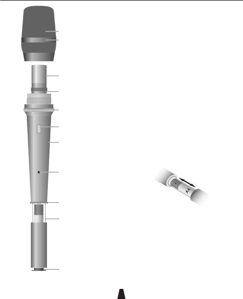
Windshield
Can be unscrewed to access the microphone capsule.
Microphone capsule
Any capsule from the Schoeps™ Colette range can be used
with the HX2040 transmitter. There are 18 different capsules
available, ranging from a hyper-cardioid to an omni pattern.
Many of the capsules are available from Audio Limited.
Identification ring and button
The HX2040 is supplied with six colour identifying rings and
buttons to aid recognition in multi-channel use.
Anti-roll ring
An anti-roll ring is fitted to the windshield to prevent the
HX2040 from rolling when placed on a flat surface, such as
a table.
Infra-red port
Receives commands from and transmits status information
back to the SwitchiR infra-red controller.
On button
Switches the microphone on.
To prevent the microphone from accidentally being switched
off during use the HX2040 can only be switched off by using
the SwitchiR, or by briefly disconnecting the battery.
On/Overload indicator
The ring above the battery compartment glows red while
the HX2040 is switched on, but will flash off to indicate an
overload if the microphone experiences a loud signal.
Battery compartment
Holds one AA 1.5V (LR6 type) alkaline battery.
Antenna
The transmitter antenna is integrated into the battery
compartment and therefore no external antenna is required.
HX2040 Hand-Held Transmitter
The HX2040 is a multi-frequency UHF hand-held transmitter for use with all the receivers from the RMS 2040, RMS
2020, and Envoy ranges. It is also compatible with the older RMS 2000 range. It provides 32 switchable frequencies,
and is configured entirely by infra-red control using the supplied SwitchiR. The HX2040 can be used with a range of
microphone capsules from the Schoeps™ Colette series, and features a robust ergonomic design with a microphone
suspension designed to minimise handling noise.
HX2040 Hand-Held Transmitter
88
21
Setting up the HX2040
.......................
To set up the HX2040 :
• Fit the battery.
• Switch on by pressing and holding the grey On button
below the infra-red port for one second.
• Check or select the operating frequency.
• Check or set the gain.
• Check or set the low frequency cut filter.
• Check the battery status.
These steps are explained below:
Fitting the battery
• Open the battery compartment by gripping the cover and
sliding it gently away from the body of the HX2040.
• Fit the battery with the positive terminal uppermost and
close the battery cover until it clicks shut.
Do not twist or turn the battery cover.
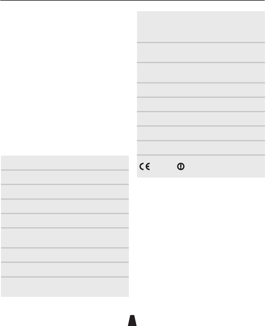
Removing the battery
The battery can easily be removed by pushing a small coin
into the slot in the compartment beneath the battery.
AA
+
Coloured
identification
button
Microphone
mount
Microphone
capsule
Windshield
Anti-roll ring
Transmitter
body
Coloured
identification
ring
Infra-red
port
On button
On/Overload
indicator
Battery
compartment
with integral
antenna

HX2040 Hand-Held Transmitter
88
22
Switching on
* Press and hold the grey On button below the infra-red
port for one second until the ring above the battery
compartment glows red.
When not in use the power should be switched off using the
SwitchiR, as described below. Alternatively the HX2040 can
be switched off by opening the battery compartment and
briefly disconnecting the battery.
Selecting the operating frequency
You can check or change the operating frequency of the
HX2040 via infra-red control using the SwitchiR.
To check the frequency:
• Press MENU.
The display shows:
FREQUENCY
MHz
Fr
• Align the front of the SwitchiR with the infra-red port on
the HX2040 and press OK.
The display shows the current
frequency; for example:
FREQUENCY
Tx MHz
854.900
To change the frequency:
• Press OK.
The display will alternately flash between showing the
frequency and channel number.
For example:
CHANNEL
01
• Press a or v to scroll through the 32 frequencies read
from the transmitter until the desired frequency or
channel is displayed.
For example:
CHANNEL
32
• Point the SwitchiR at the infra-red port on the HX2040 and
press OK.
If the command was received successfully the display will
show the new set frequency.
For example:
FREQUENCY
Tx MHz
857.950
Otherwise it will show:
Error
• Repeat the above steps if an error message is displayed,
moving the SwitchiR closer to the infra-red port.
Setting the gain
The steps between 0-9 gain settings are approximately 3
to 4dB. Set the gain position so that the Overload indicator
does not flash off during normal operation. A typical setting
is 6 or 7.
To check the gain setting:
• Press MENU followed by a.

HX2040 Hand-Held Transmitter
88
23
The display will indicate:
AF LEVEL
TxRx
AF
• Align the front of the SwitchiR with the infra-red port of
the HX2040 and press OK.
The display will show the current
transmitter gain setting:
AF LEVEL
Tx
0
To change the gain setting:
• Press OK again.
The display will flash the level setting.
• Press a or v to step between gain settings 0-9 until the
required gain setting is displayed.
For example:
!&,%6%,
4X
• Align the front of the SwitchiR with the infra-red port on
the transmitter and press OK.
If the command was received correctly the display will show
the new gain setting.
For example:
!&,%6%,
4X
Otherwise the display shows:
Error
• Repeat the previous steps if an error message is
displayed, moving the SwitchiR closer to the infra-red
port.
Setting the low frequency cut filter
The LF cut filter gives an approximately 10dB cut at 50Hz to
reduce handling and wind noise.
To check the status of the low frequency cut filter:
• Press MENU
• Press a twice until the
display shows:
Tx
LF Cut
• Align the front of the SwitchiR with the infra-red port on
the transmitter and press OK.
The current LF cut filter setting
is displayed; for example:
Tx
OFF
To change the filter setting:
• Press OK again.
The current setting will flash.
• Press a or v to toggle between ON or OFF until the
required setting is displayed.
• Align the front of the SwitchiR with the infra-red port on
the transmitter and press OK.
If the command was received successfully the new setting
will be displayed.
For example:
Tx
On

HX2040 Hand-Held Transmitter
88
24
Otherwise the display will show:
Error
• Repeat the previous steps if an error message is
displayed, moving the SwitchiR closer to the infra-red
port.
Checking the battery status
• Press MENU.
• Press a three times until
the display shows:
TxRx
BAtt
• Align the front of the SwitchiR with the infra-red port on
the transmitter and press OK.
The display will show the
current battery status:
Tx
1.25v
The battery level can also be checked from the receiver; see
the appropriate instructions for the receiver.
Infra-red disable
........................
You can protect the HX2040 from an accidental change
of settings, such as in a live performance, by disabling
the infra-red port on the transmitter. This will prevent
all communication to the transmitter until the battery is
disconnected and reconnected.
Disabling the infra-red port
• Press MENU.
• Press v twice.
The display
will show:
TxRx
dISABLE
TxRx
Ir ?
• Align the front of the SwitchiR with the infra-red port on
the transmitter and press OK.
If the command was received
successfully the display will show:
Tx
Ir OFF
Note: Once the infra-red port has been disabled, any
subsequent interrogation of the transmitter will give an Error
display; this is not a fault.
Fitting the microphone capsule
.......................
The HX2040 transmitter uses high quality interchangeable
condensor capsules from the Schoeps™ Colette range. The
HX2040 is compatible with the full range of capsules and
accessories in this range.
The capsule mounting has a unique gel-based suspension to
minimise handling noise.
To fit a capsule
• Unscrew the metal windscreen from the top of the
transmitter.
• Screw the capsule into place taking care not to cross-
thread the capsule or over-tighten it.
• Replace the windscreen.
HX2040 Hand-Held Transmitter
88
25
Holding the HX2040
.......................
The HX2040 should be held above the illuminated On/
Overload indicator ring. This will enable maximum power
to be radiated from the integral antenna in the battery
compartment. Holding the HX2040 over the battery
compartment will impair the range of the transmitter and
should be avoided.
The frequency, gain, and LF status setting will be retained
even if the battery is removed from the transmitter.
An external foam windshield is available from Audio Limited.
Technical specification
.......................
Frequency range 470MHz–1000MHz
Number of frequencies 32 pre-programmed
Switching range Up to 24MHz
Output power 10mW nominal
Gain control range 30dB in 10 steps
Frequency response 50Hz to 18kHz ±1dB excluding
capsule
THD <0.2% typical
Battery 1.5V AA cell (IEC LR6) Alkaline
Battery life Typically 5 hours with an alkaline
battery
Available capsules A02S bright omni
AC4 cardioid
AC4A cardioid for vocal use and
others from Schoeps™ Colette range
Indicators Red LED for on;
LED off indicates overload
Other Specially designed suspension
minimises handling noise
Length 260mm including windshield
Diameter 44/36mm reducing to 22mm at base
Weight 185g
Operating temperature -20°C to +55°C range
Compliant to R&TTE Directive FCC
0891
CHAPTER
6
88
26
<>
Menu
OK
Controls
........................
V
V
FREQUENCY
MHz
Fr
Display
Scroll buttons
Menu/On button
9V battery
tester
Infra-red port
+
_
OK button
Infra-red port
Point the infra-red port at the front of the SwitchiR directly at
the infra-red port of the transmitter or receiver, keeping the
SwitchiR within 30cm of the port.
Menu/On button
Turns on the SwitchiR . The display will initially show the
frequency screen:
FREQUENCY
MHz
Fr
a/v Scroll buttons
Allow you to scroll through the menus, or the selections on
the frequency, audio level, and LF cut screens.
OK button
Confirms the current selection.
Power saving feature
The SwitchiR will switch off if no buttons are pressed within
30 seconds, to conserve battery life.
The SwitchiR will also switch off automatically if the
menu button is kept pressed for more than 50 seconds; for
example while the SwitchiR is in a pocket or bag.
SwitchiR Infra-Red Controller
The SwitchiR is a compact custom-designed infra-red controller for use with the 2040 Range. It provides functions
to allow you to read the status of a device, or change its settings. In addition it includes a convenient built-in 9V
battery tester:
SwitchiR Infra-Red Controller
88
27
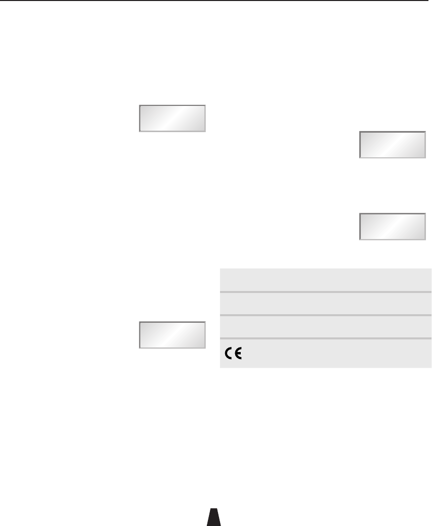
Using SwitchiR
........................
Full instructions for using SwitchiR with each of the products
in the 2040 Range are given in the appropriate chapter of
this guide.
The following table summarises the SwitchiR functions, and
describes the additional functions included in SwitchiR .
Menu Description
Fr Press OK to read the transmitter or receiver
frequency setting. Press OK again followed by a
or v to select a new frequency, and press OK to
transmit it to the unit.
AF Press OK to read the receiver or transmitter audio
level. Press OK again followed by a or v to select
a new audio level and press OK to transmit it to the
unit.
LF Cut Press OK to read the transmitter’s LF cut setting.
Press OK again followed by a or v to switch the
setting between on or off and press OK to transmit
it to the unit.
Batt Press OK to read the transmitter or receiver
battery level. For receivers the receiver battery
level alternates with a transmitter battery status
indicator: H (high), L (low), or F (fail).
Int Batt Displays the battery voltage of the SwitchiR internal
battery. If this falls below 5.00V the internal battery
should be replaced.
9V Batt Allows you to test a 9V 6LR61 type battery by
holding it against the two metal terminals on the
side of the SwitchiR. A reverse polarity warning is
displayed if the battery is connected the wrong way
round.
Menu Description
Sn Press OK to read the serial number of a receiver or
transmitter and display it on the display. The serial
number consists of a six-digit prefix followed by a
two-digit suffix, and these are flashed alternately on
the display.
User ID Displays the unit’s user ID. You can edit the user ID
using the AudiR™ application.
iR disable Press OK to disable the infra-red port on a
transmitter or receiver until power is disconnected
and reapplied.
Off Press OK to turn a transmitter off. Not available for
receivers.
Technical specification
........................
Size 65 x 30 x 11mm (17mm at battery end)
Weight 20g including battery
Battery type 6V PX28L Lithium or equivalent
CHAPTER
7
88
28
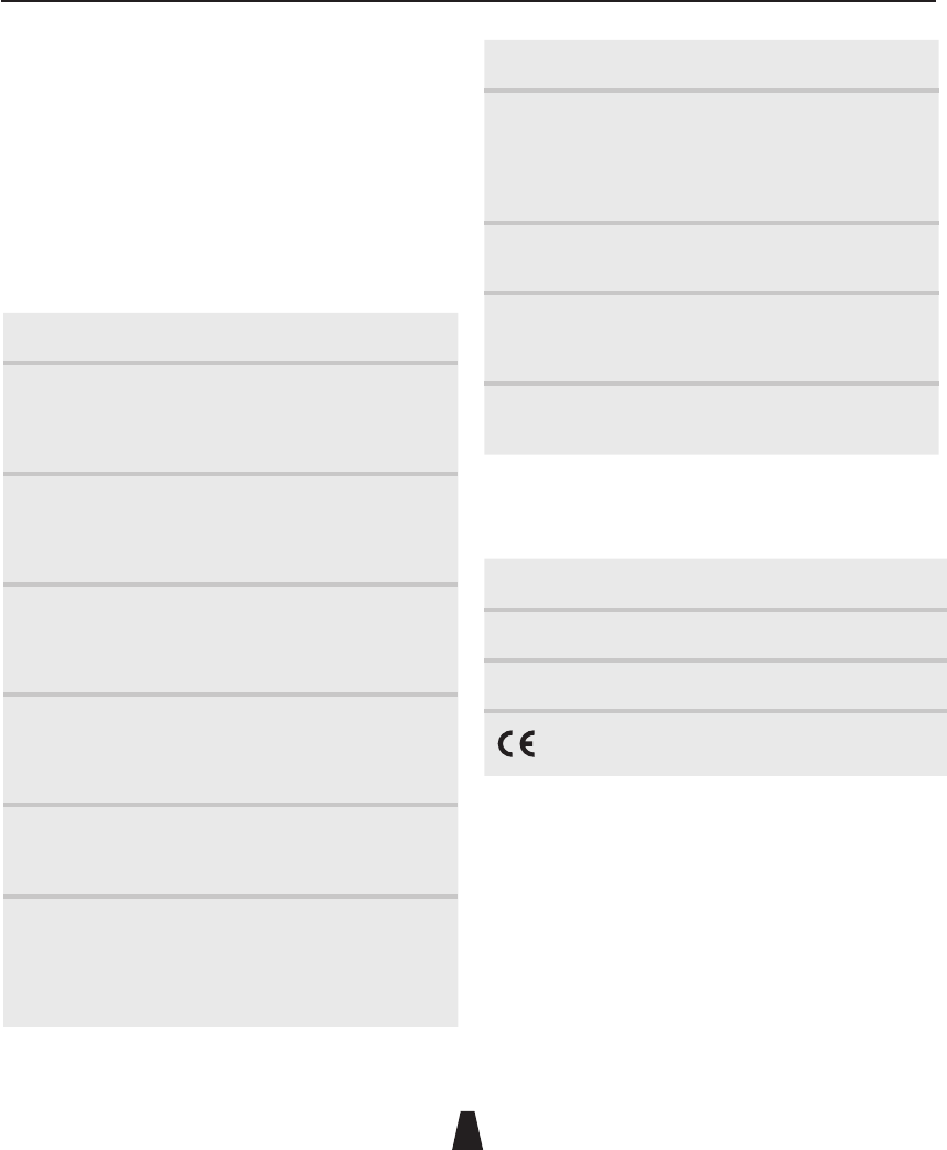
Controls, display, and connections
........................
ÀiiÊ"
`V>ÌÀ
" ÊLÕÌÌ
i
ViVÌÀ
,i`Ê"
`V>ÌÀ
>ÌÌiÀÞ
VÌ>VÌÃ
"ÊLÕÌÌ
>ÌÌiÀÞÊ
V«>ÀÌiÌ
"
Lemo connector
Allows you to plug in a TX2040, TX2020, or DX2020 and
measure its on-load internal battery voltage.
Battery contacts
Allow you to measure the voltage of a 9V 6LR61 type battery.
Red off indicator
Indicates no signal from the transmitter.
Green on indicator
Indicates a signal received from the transmitter.
Display
Shows the status of the Control-X, and displays frequency
and voltage.
ON/OFF buttons
For turning the pocket transmitter on or off.
Battery compartment
Takes a 9V 6LR61 type battery.
Controlling a miniTX or TX2040
........................
In the miniTX the receptor for the Control-X is located in the
top part of the transmitter between the Lemo socket and the
antenna socket.
In the TX2040 the receptor for the Control-X is located
in the bottom part of the transmitter below the battery
compartment.
Control-X Transmitter Controller
The Control-X uses electromagnetic induction to switch on or off the miniTX or the TX2040 transmitter, or check its
frequency, even when the transmitter is hidden beneath clothing. It has a built-in frequency counter and battery
tester.

Control-X Transmitter Controller
88
29
Switching on
To switch the miniTX or TX2040 on, even through clothing:
• Hold the Control-X within 20cm (8") of the transmitter.
• Press and hold the ON button and slowly wave the
Control-X in front of the transmitter.
The green indicator illuminates
and the display shows:
tr On
• Release the ON button.
The green indicator stays illuminated if a signal is being
received from the transmitter, and the display shows the
frequency.
For example:
MHz
856.575
FREQUENCY
Switching off
• Hold the Control-X within 20cm (8") of the transmitter.
• Press and hold the OFF button and slowly wave the
Control-X in fromt of the transmitter.
The red indicator illuminates
and the display shows:
tr OFF
• Release the OFF button.
The red indicator stays illuminated
and the display then shows:
no SIG
This confirms that the transmitter has been switched off.
Checking whether the miniTX or TX2040 is switched on
You can use the Control-X to check the status of the
transmitter, without switching it on or off, as follows:
• Hold the Control-X more than 20cm (8") away from the
transmitter, and press and release the ON button.
• Move the Control-X within 20cm (8") of the transmitter.
If the transmitter is operating the green indicator will be
illuminated and the display shows the frequency.
For example:
MHz
856.575
FREQUENCY
If the transmitter is not operating the red indicator will be
illuminated.
The display shows:
no SIG
Displaying the frequency of any
transmitter
........................
The Control-X can be used to display the frequency of any
Audio Ltd or third-party transmitter.
Displaying transmitter frequency
• Bring the transmitter within 5cm (2”) of the Control-X.
• Hold down the ON button.
The display shows the transmitter
frequency; for example:
MHz
856.575
FREQUENCY
Control-X Transmitter Controller
88
30
Checking battery voltages
........................
Checking the Control-X battery
• Press the ON and OFF buttons simultaneously, and
release them.
The display briefly shows the battery
voltage of the Control-X; for example:
7.60u
If this falls below 6V the battery should be replaced.
Note that the Control-X automatically switches itself off if no
key has been pressed for approximately 12 seconds.
Checking the battery of other Audio Ltd RMS2020 or
RMS2000 transmitters
• Plug the transmitter into the Lemo connector on the front
of the Control-X without pressing either button.
The display shows the true on-load internal battery voltage
of the unit.
For example:
8.55u
Refer to the User Guide for the product for information about
the minimum voltage requirement of the product.
Note: Although the Control-X display automatically turns off
to conserve battery life, the transmitter will remain on while
connected to the Control-X.
Measuring a battery
• Hold the 9V 6LR61 type battery against the two metal
terminals on the side of the Control-X without pressing
any buttons.
The green indicator will be illuminated and the battery
voltage will be displayed.
For example:
8.25u
If the battery is connected the wrong way round the
indicator will be illuminated.
The display shows:
ReVeRse
Technical specification
........................
Size 100 x 63 x 24mm
Weight 150g including battery
Battery type 9V 6LR61

Declaration of conformity
88
31
EC Declaration of Conformity
Déclaration de conformité pour la CEE
EG-Konformitäts-Erklärung
Certificato di conformitá comunitario
Declaración de Conformidad
EG-Conformiteitsverklaring
AUDIO LIMITED
Audio House, Progress Road High, Wycombe, HP12 4JD, U.K.
declare that these devices / déclarons que ces appareils / erklären, dass
die Produkte / declaramos que estos aparatos / dichiaria che questi
apparecchi / verklaren, dat deze toestelen
TX2040 Pocket Transmitter
HX2040 Handheld Transmitter
conform to the essential requirements of the R&TTE Directive 1999/5/EC. To
demonstrate compliance with these requirements, the following standards
were consulted:
sont conformes aux prescriptions fondamentales dan la Directive R&TTE
1999/5/EC. Pour mettre en pratique dans la règle de l’art les prescriptions,il
a été tenu compte des normes suivantes:
den einschlägigen Anforderungen der R&TTE-Direktive 1999/5/EC
entsprechen. Zur sachgemäßen Umsetzung der in den EG-Richtlinien
genannten Anforderungen wurden folgende Norman herangezogen:
complen los requimientos básicos de la normativa de la normativa R&TTE
1999/5/EC. Con il fin de realizar de forma adecuada los requirimientos
referidos en la normativa fueron consaltadas las siguientes normativas:
sono conformi alla normativa R&TTE 1999/5/EC. Per un’appropriato
risconto nell’ambito della normativa CEE sono state consultate le seguenti
normative:
evereenkomt met de basiseisen van de EG-Richtlijn 1999/5/EC. Om de eisen,
die in de EG-Richtlijnen vermeld zijn, in juiste vorm om te zetten, zijn van
volgende normen gebruik gemaakt:
Article 3.1a: EN 60065:2002 (Safety of Electrical Equipment)
Article 3.1b: EN 301 489-9:2002 (Electromagnetic Compatibility)
Article 3.2: EN 300 422-2:2000 (Radio Performance)
Conformity assessed via Annex IV using a Technical Construction. File
examined by Notified Body 0891, TRL Compliance Services Ltd.
May 2004
Lee Stone
(Technical Director)