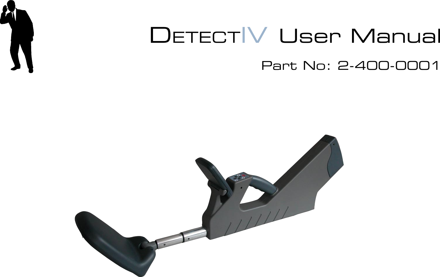
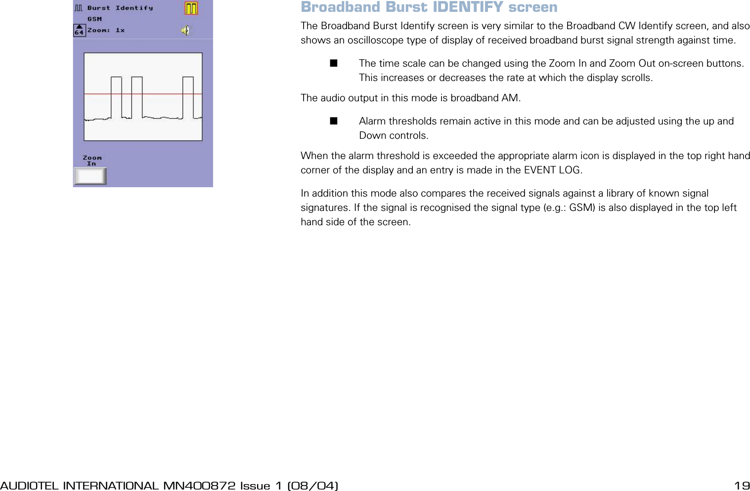
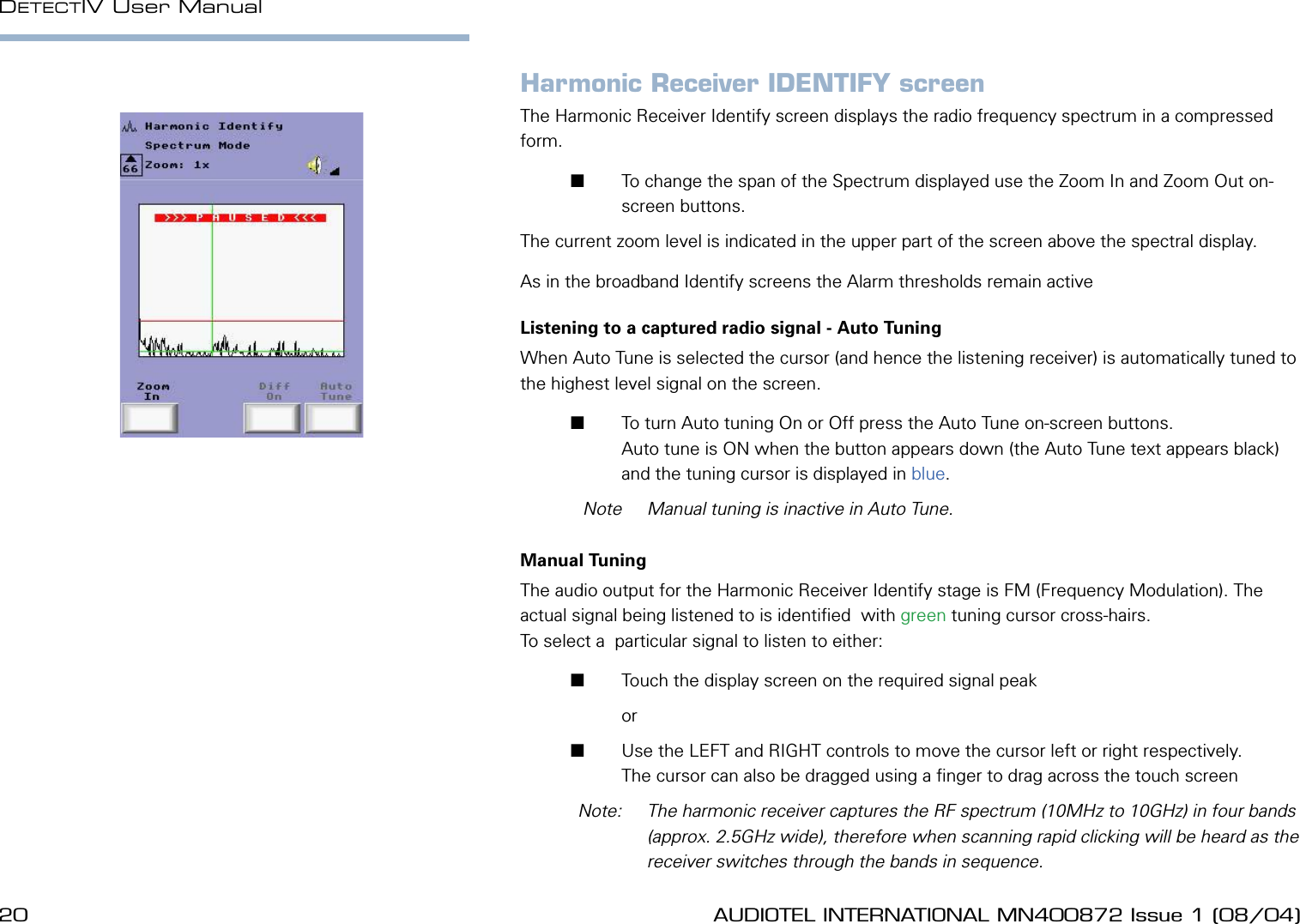
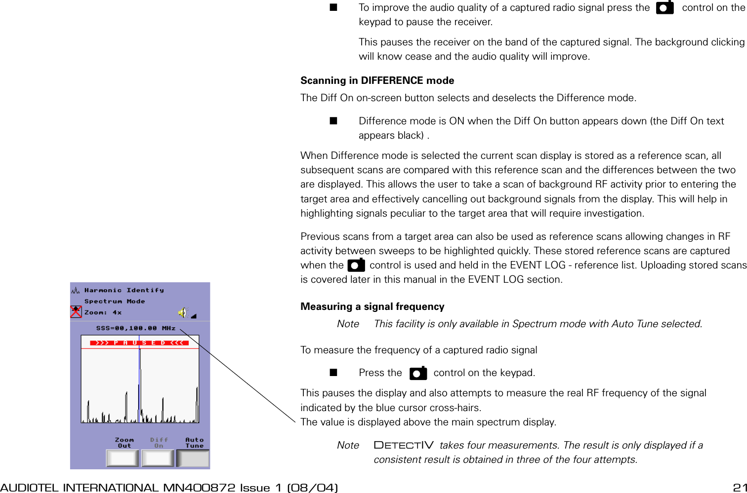
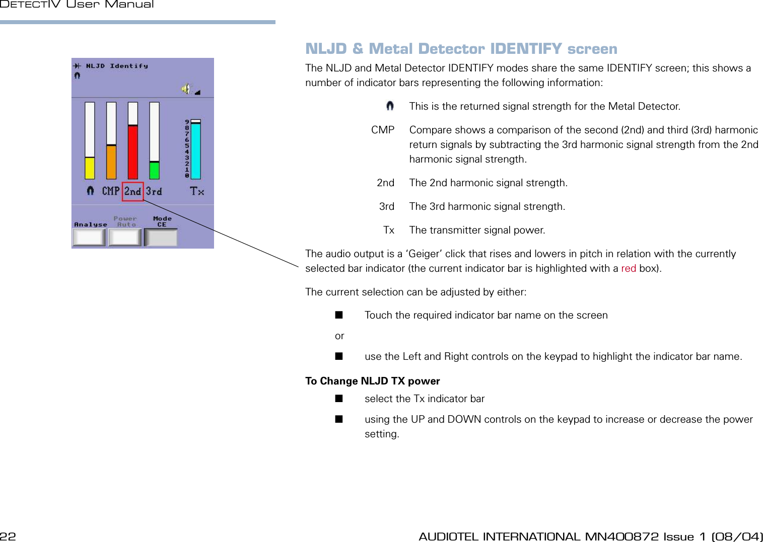
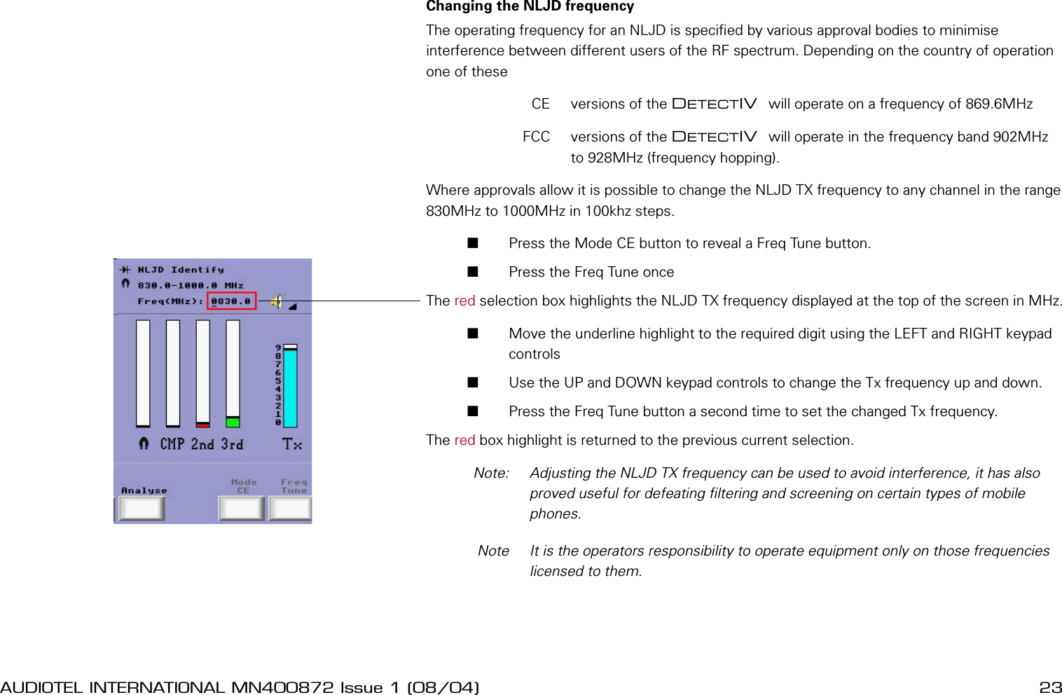
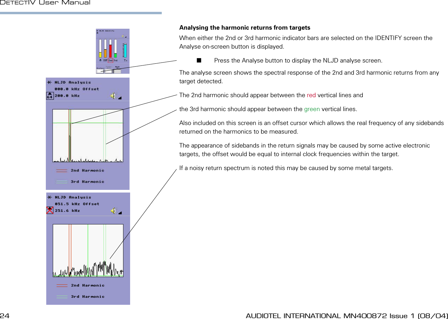
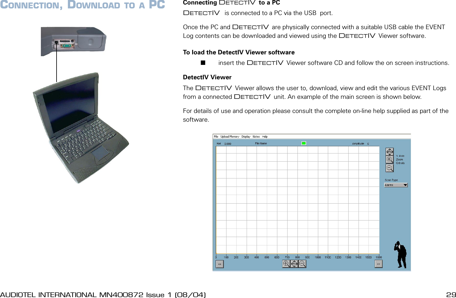
Audiotel 2-400-0001 DETECT IV Portable handheld covert Tx detector User Manual DetectIV iss 1 1
Audiotel International Limited DETECT IV Portable handheld covert Tx detector DetectIV iss 1 1
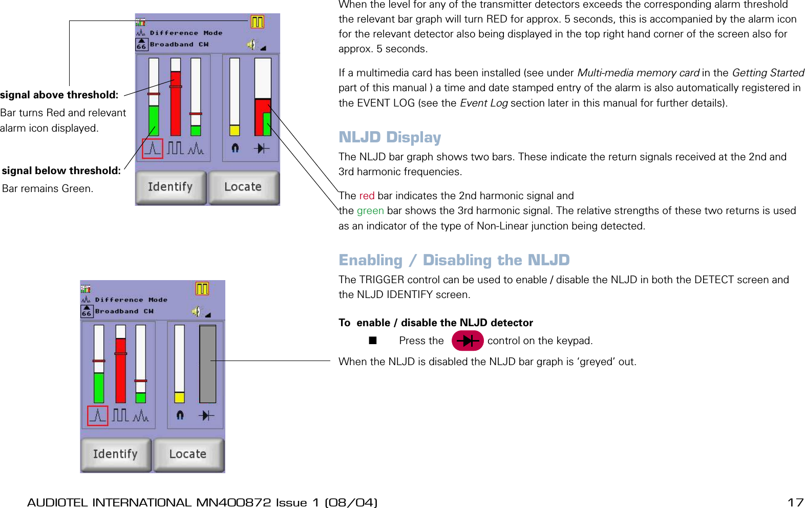
Audiotel >
Contents
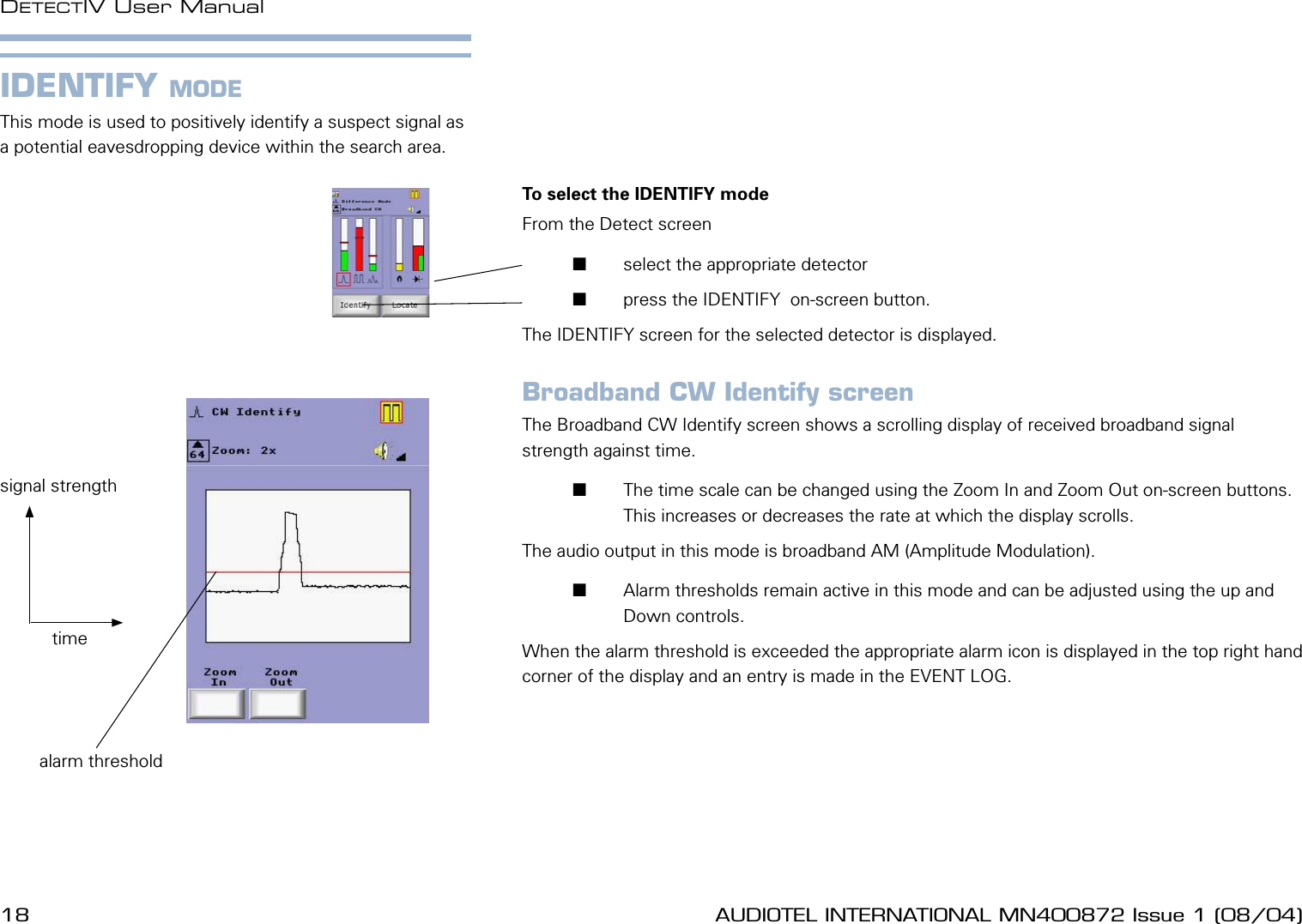
- 1. User Manual
- 2. User manual
User manual