Aurion Srl ZWTX07 EMG module for Electromyograph User Manual Multilanguage HW
Aurion Srl EMG module for Electromyograph Multilanguage HW
User Manual

USER MANUAL COD. ZW04 REV 10
04/10/05 Pag. 1
ZEROWIRE MULTICHANNEL
ELECTROMYOGRAPH
USER MANUAL
This device complies with Part 15 of the FCC Rules. Operation is subject to the following two con-
ditions: (1) this device may not cause harmful interference, and (2) this device must accept any in-
terference received, including interference that may cause undesired operation.
Changes or modifications not expressly approved by the party responsible for compliance could
void the user’s authority to operate the equipment.

USER MANUAL COD. ZW04 REV 10
04/10/05 Pag. 2
1. INTRODUCTION ........................................................................................................................ 2
2. DESTINATION AND CLASSIFICATION................................................................................ 3
2.1 HOW TO USE IT....................................................................................................................... 4
3. ZEROWIRE SYSTEM COMPONENTS ................................................................................... 5
3.1 WIRELESS ELECTRODES ......................................................................................................... 6
3.2 BASE UNIT ............................................................................................................................. 7
3.3 DOCKING MODULE ................................................................................................................. 8
4. ZEROWIRE SYSTEM USE........................................................................................................ 9
4.1 ANALOG MODE ...................................................................................................................... 9
4.1.1 Supported external devices............................................................................................. 10
4.1.2 Layout of cable connections........................................................................................... 11
4.2 DIGITAL MODE ..................................................................................................................... 12
4.2.1 External trigger.............................................................................................................. 13
4.2.1.1 Trig in..................................................................................................................................14
4.2.1.2 Trig out................................................................................................................................14
4.2.2 Supported external devices............................................................................................. 14
4.3 LED STATUS INDICATORS .................................................................................................... 15
4.4 PREGELLED ELECTRODES..................................................................................................... 15
4.5 ELECTRODES BATTERY RECHARGE ...................................................................................... 15
4.6 LED INDICATOR DURING CHARGING .................................................................................... 16
4.7 WARNINGS........................................................................................................................... 16
4.8 PIEZORESISTIVE SENSORS..................................................................................................... 18
5. SYSTEM MAINTENANCE ...................................................................................................... 20
5.1 REPAIRABLE PARTS.............................................................................................................. 20
5.2 REPLACEMENT OF ELECTRODE BATTERY............................................................................. 20
5.2.1 Module identification ..................................................................................................... 21
5.3 WARNINGS ABOUT ELECTRODES BATTERY........................................................................... 21
5.4 WARNINGS FOR BATTERY DISPOSAL..................................................................................... 22
5.5 WARNINGS FOR DEVICE DISPOSAL........................................................................................ 22
5.6 REPLACEMENT OF WORN PARTS........................................................................................... 22
5.7 ZEROWIRE CLEANING .......................................................................................................... 23
5.8 REFERENCES........................................................................................................................ 23
6. TECHNICAL SPECIFICATIONS ........................................................................................... 24
6.1 SUITABILITY......................................................................................................................... 26

USER MANUAL COD. ZW04 REV 10
04/10/05 Pag. 3
1. INTRODUCTION
ZeroWire system is an innovative multi-channel wireless surface electromyographic system.
The leading specifications of this new system are:
• Wireless and low-power electrodes for a quick patient set-up and for movements performed in total
freedom;
• Digital transmission of the EMG signal;
• Receiver device equipped with analog and digital (USB port) data output;
• Developed with high integration “SMD” technology;
• Compatible with ISM standard – low power devices (ETSI, FCC, JAPAN);
• Designed to be integrated with lab equipment for multipurpose acquisition systems.
2. DESTINATION AND CLASSIFICATION
ZeroWire is a system for the data collection of biologic signals; the main system feature is the absence
of cables between the transmitters on the patient and the data receiver/recording unit.
This allows the acquisition of EMG signal while patient is free to move.
This feature is very useful for clinical and scientific applications, for example in pathologic gait analy-
sis or in rehabilitation.
Low invasivity and high safety allow to use ZeroWire system for patients who tolerate the adhesive
elelctrodes and conductive gel for SEMG detection through medical electrodes.
ZeroWire system application areas are:
• Neurology;
• Physiatry and rehabilitation;
• Orthopedy;
• Ergonomics;
• Sport medicine;
• Veterinary.
USER MANUAL COD. ZW04 REV 10
04/10/05 Pag. 4
ZeroWire system is classified according to CEI 60601-1:1998:
- The applied part is a BF type according to CEI EN 60601-2-40 regulation (icon):
- Second class device working with an external power supply providing power to internal peripheral
units; lithium rechargeable battery (icon):
- IPX0 protection degree of shells (NOT water proof);
- Functioning type: continuous.
2.1 How to use it
To use ZeroWire, two pre-gelled disposable electrodes for each channel have to be applied to the
subject. The EMG acquisition module is applied on the surface electrodes using a snap connector.
If required by the exam, piezoelectric sensors are applied for the identification of plantar supports; the
foot-switch acquisition module is applied to the sensor by the appropriate cables.
ZeroWire system can be used by doctors, paramedics and technicians.
To use ZeroWire system, please, read carefully the instructions in the relative chapter.
USER MANUAL COD. ZW04 REV 10
04/10/05 Pag. 5
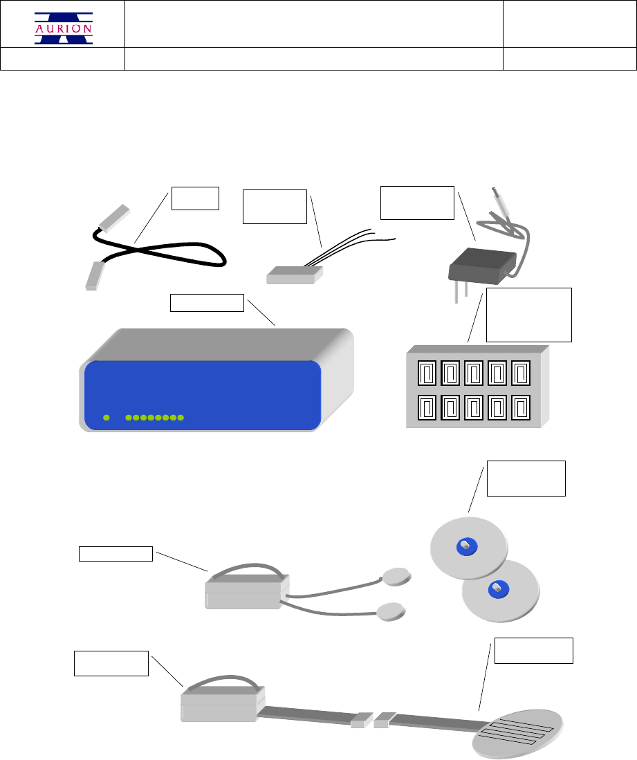
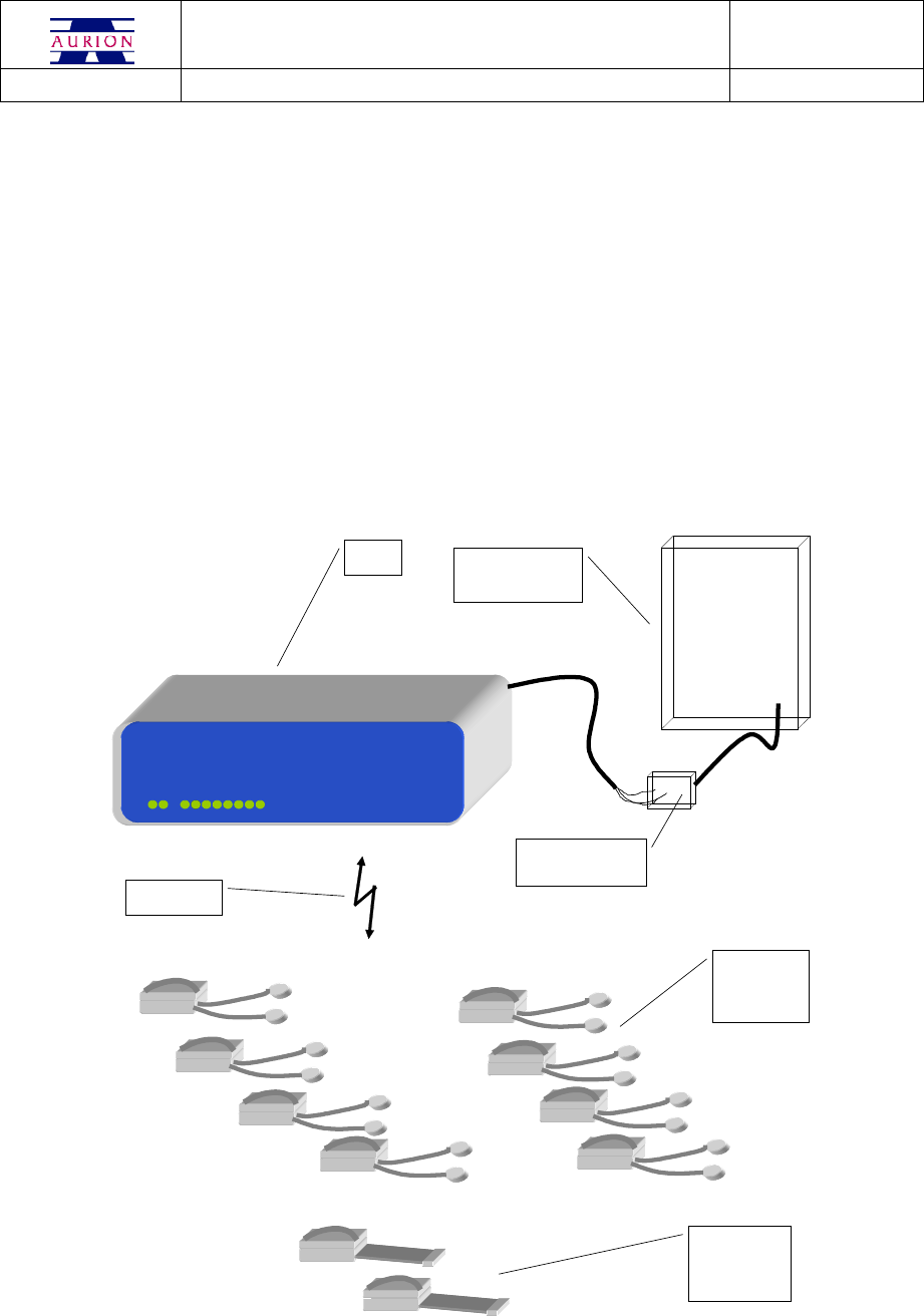
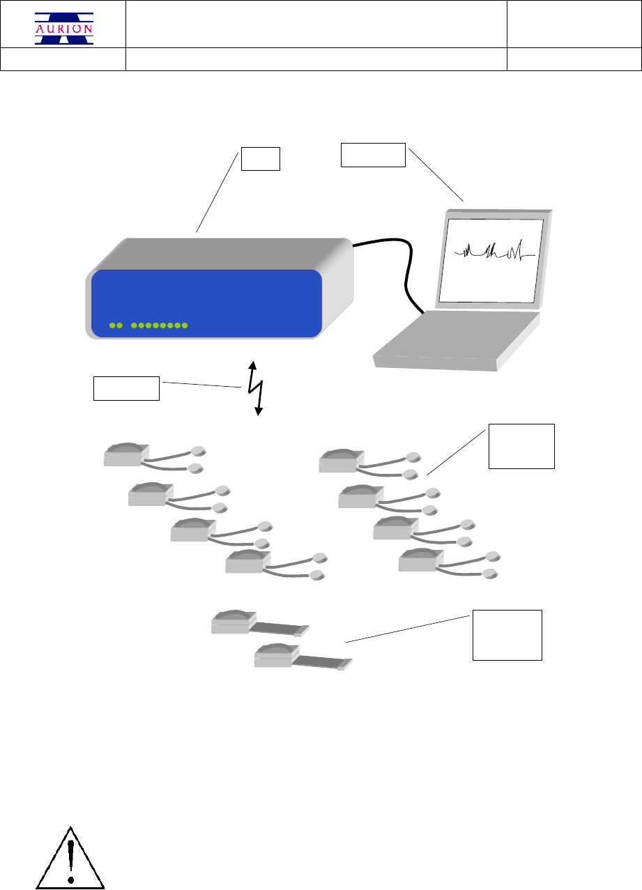
3. ZEROWIRE SYSTEM COMPONENTS
The following representation shows all ZeroWire components.
USB
CABLE
ANALOG
OUTPUT
CABLE
SWITCHING
MEDICAL
POWER SUPPLY
BASE UNIT
FOOTSWITCHES
MODULE
PREGELLED
DISPOSABLE
ELECTRODES
PIEZORESISTIVE
SENSOR
DOCKING MODULE
FOR EMG AND
FOOTSWITCHES
MODULES
RE-CHARGING
EMG MODULE
The standard configuration of the system is composed of:
EMG wireless modules, whit snap connections to the electrodes;
two wireless modules, to transmit gait cycle events (footswitches);
a receiver unit;
a docking box to recharge the wireless modules.
Wireless modules are equipped with an internal rechargeable battery. The modules communicate with
PC through the base unit thanks to a bi-directional link working at 2400 MHz.
USER MANUAL COD. ZW04 REV 10
04/10/05 Pag. 6
When not used, modules should be displaced in the dedicated areas of the docking box to receive
energy for battery recharge.
An automatic system for power saving optimise battery life during those phases in which the electrodes
are not used.
3.1 Wireless electrodes
EMG
ACQUISITION
MODULE
POWER SUPPLY
AND EMG INPUT
MODULE
POWER SUPPLY
AND
FOOTSWITCHES
INPUT MODULE
FOOTSWITCHES
ACQUISITION
MODULE
The ZeroWire system module is composed of two parts:
the conditioning signal module, with active circuitry for signal radio-transmission;
power supply module and I/O interface including rechargeable battery, recharge coil, and the
connections to the detection points.
The power supply module is connected to the acquisition unit through a sliding mechanism; the unit
disassembly should be done only during maintenance (exhausted battery or electric wire wear). In these
cases follow the instructions in chapter “Replacement of electrode battery”.
USER MANUAL COD. ZW04 REV 10
04/10/05 Pag. 7
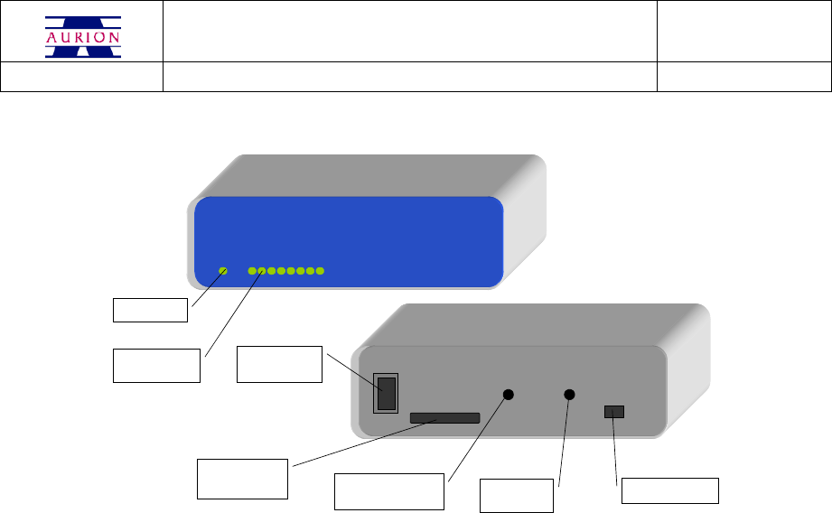
3.2 Base unit
ELECTRODES
STATUS LED
ON-OFF
SWITCH
POWER SUPPLY
PLUG USB PORT
EXTERNAL
TRIGGER
ANALOG
OUTPUT
CONNECTOR
LED ON
The base unit has a front panel with status LEDs.
The signals are:
• LED off: the electrode is non active;
• LED on: green light: the electrode is active.
The front panel has also a further green LED indicating the on/off status of the base unit.
On the rear panel:
• on-off switch;
• female port DB25 for analog EMG output and for foot switches signals;
• jack for the connection of the external trigger;
• USB port to connect the host PC.
The base unit has a RF transceiver at 2,4 GHz, a microprocessor for data synchronisation and separa-
tion, D/A converter, a USB port to connect the host PC.
USER MANUAL COD. ZW04 REV 10
04/10/05 Pag. 8
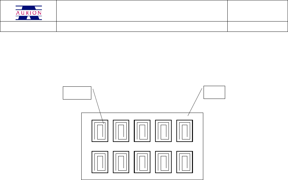
3.3 Docking module
When not in use, wireless electrodes should be in the docking; it recharges the batteries.
DOCKING
INDUCTION
COIL
The recharge occurs by coils, attached to the electrodes support base and on the layer of the charger;
the energy transfer occurs via induction.
Coils on the docking are excited to resonance by adequate impulses in frequency and amplitude; when
the electrode is on the docking, there is an induced alternate current in the electrode coil that will be
sent to the battery for its recharging.
USER MANUAL COD. ZW04 REV 10
04/10/05 Pag. 9
4. ZEROWIRE SYSTEM USE
ZeroWire system can be used in two different configurations:
• linked to an A/D converter for visualisation and analog storage of EMG and basography
data, adopting external devices ;
• linked to a PC through the USB port for visualisation, system control and digital data stor-
age of EMG and basography.
The two configurations can be used simultaneously.
4.1 Analog mode
ANALOG DEVICE
FOR EXTERNAL
ACQUISITION
TWO
ELECTRODES
FOR
FOOTSWITCHES
ACQUISITION
EIGHT
ELECTRODES
FOR EMG
ACQUISITION
BASE
UNIT
RADIO LINK
2,4 GHz
HARDWARE
INTERCONNECTION
BOX
USER MANUAL COD. ZW04 REV 10
04/10/05 Pag. 10
To operate the system:
1) connect ZeroWire Y1 cable (analog output) to the analog A/D interface of the external de-
vice
2) if required, connect the trigger cable to the external device.Check trigger electric features
(voltage and timing) adopted by the system (see “Technical specifications” chapter)
3) connect ZeroWire power supply and switch on the system
The system can be powered only with Friwo FW7555M/09 power supply provided by the
producer; the use of other power supply units can cause electric shock and damage the
system.
If used in analog mode, the system doesn’t require a Personal Computer; switching
on the base unit EMG and basographic signals are available in continuous on analog output connector
J13.
4.1.1 Supported external devices
The ZeroWire system can be connected to analog devices commonly used in clinical and scientific en-
vironments; these are the features required by systems:
• at least eight EMG data collection channels, with Zout = 100 ohm and an amplitude of ± 2,5 V
• at least two analog channels to acquire footswitches, configured for signals with Zout = 100
ohm and an amplitude of + 4 V.
• it complies with IEC 60950
The use of external devices non complying with IEC 60950 can cause electric
shock and damage the system.
USER MANUAL COD. ZW04 REV 10
04/10/05 Pag. 11
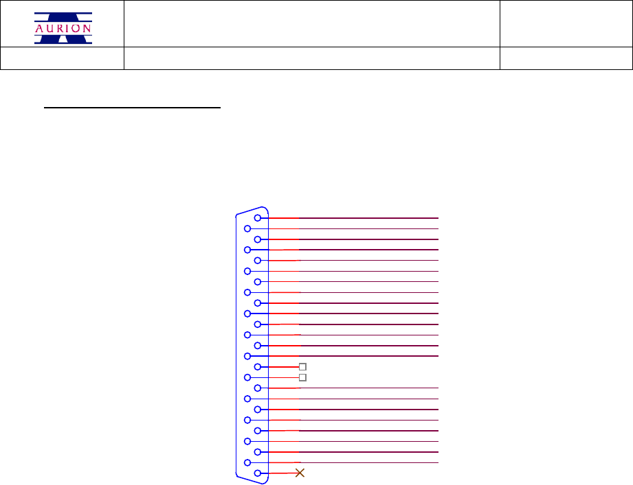
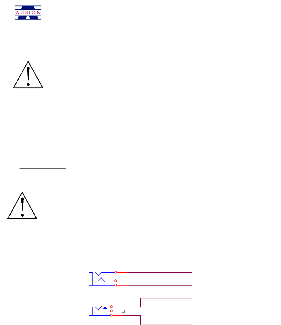
4.1.2 Layout of cable connections
Pin out of the analog output connector.
25-pin female socket (“D” type)
#2_
#2_AGND
13
25
12
24
11
23
10
22
9
21
8
20
7
19
6
18
5
17
4
16
3
15
2
14
1
J15
#1_FSWA_ANA
#1_FSWB_ANA
#1_AGND
#2_AGND#2_AGND
#1_AGND
#2_CH10
#2_CH9
#1_CH7#1_CH7#1_CH7#1_CH7#1_CH7#1_CH7
#1_CH5#1_CH5#1_CH5#1_CH5#1_CH5#1_CH5
#1_CH6#1_CH6#1_CH6#1_CH6#1_CH6#1_CH6#1_CH6#1_CH6#1_CH6#1_CH6
#1_CH2#1_CH2#1_CH2#1_CH2#1_CH2#1_CH2#1_CH2#1_CH2#1_CH2#1_CH2
#1_CH3#1_CH3#1_CH3#1_CH3#1_CH3#1_CH3
#1_CH4#1_CH4#1_CH4#1_CH4#1_CH4#1_CH4
#1_CH8
#1_CH1#1_CH1#1_CH1#1_CH1#1_CH1#1_CH1#1_CH1#1_CH1#1_CH1#1_CH1
#2_CH11
#2_CH12
#2_CH13
#2_CH14
#2_CH15
#2_CH16
USER MANUAL COD. ZW04 REV 10
04/10/05 Pag. 12
4.2 Digital mode
PERSONAL
COMPUTER
TWO
ELECTRODES
FOR
FOOTSWITCHES
ACQUISITION
EIGHT
ELECTRODES
FOR EMG
ACQUISITION
BASE
UNIT
RADIO LINK
2,4 GHz
To operate the system:
1. connect ZeroWire USB cable to the PC USB port
The use of Personal Computer non complying with IEC 60950 can cause electric shock
and damage the system. The use of Personal Computer non complying with IEC 60950 is
allowed using a medical class insulation transformer to power the PC.
2. if required, connect the trigger cable to the external device, after checking trigger electric fea-
ture (voltage and timing) adopted by the system (read “Technical specifications” chapter)
USER MANUAL COD. ZW04 REV 10
04/10/05 Pag. 13
3. connect ZeroWire power supply and switch on the system
The system can be powered only with Friwo FW7555M/09 power supply provided
by the producer; the use of other power supply units can cause electric shock and
damage the system.
4. open ZeroWire control program and follow the SW indication for data graphic rendering and
digital data collection.
The PC controls ZeroWire system. See SW User Manual for the description of operating controls.
4.2.1 External trigger
ZeroWire has a connector for external trigger of data capture. External trigger lines are not insulated
from the ZeroWire system ground.
The use of external devices non complying with IEC 60950 can cause electric shock
and damage the system.
Pin out of connections to trigger and power supply:
+9V
0V
TRIG_IN
TRIG_OUT
GND
J7
J10

USER MANUAL COD. ZW04 REV 10
04/10/05 Pag. 14
4.2.1.1 Trig in
Data capture can be synchronised with an external trigger signal. If required, connect the trigger cable
to the external device after checking that the trigger control complies with the electric features required
by the system (see “Technical Specifications”).
Trigger logic:
1) data acquisition if the “trigger in” signal is at “1” logic level
2) no data acquisition if the “trigger in” signal is at “0” logic level
The default condition of the line is “1”.
4.2.1.2 Trig out
A “trigger out” channel shows the system status:
1) “trig out” signal at “1” logic level when the system is acquiring
2) “trig out” signal at “0” logic level when the system is not acquiring
4.2.2 Supported external devices
ZeroWire system can be connected to any PC with USB interface; these are the features required by
systems:
type 2 USB interface
windows 2000 or XP
VGA graphic card with a resolution of 1024 x 768 at least
minimum ram memory, 512 MB
minimum processor frequency, 800 MHz
minimum hard disk, 20 GB
The Personal Computer linked with the ZeroWire system has to comply with IEC 60950 regulation.
ZeroWire system has a software for data collection and system set-up; for additional details see the user
manual provided with the SW.

USER MANUAL COD. ZW04 REV 10
04/10/05 Pag. 15
4.3 LED status indicators
During ZeroWire functioning, LEDs are used to indicate the functioning status of the system.
On the base unit there are ten LEDs:
- LED off: the correspondent electrode is in stand–by (non active);
- LED on, green light: the electrode is on
On the EMG unit there is one LED:
- LED off: the electrode is in stand–by condition (not active);
- LED on, green light: the electrode is on and recognised by the receiver unit;
- LED on, blinking green light: the electrode is on and has a low battery level.
4.4 Pregelled electrodes
The ZeroWire system can be used with single-use pre-gelled electrodes equipped with snaps. Pre-gelled
electrodes are available in different dimensions, and may be purchased through Noraxon USA ora local
distributor of consumable items.
To apply electrodes see the information provided by the manufacture.
Warning: the quality of the EMG signal acquired by the ZeroWire system is linked to the quality of the
contact between electrode and skin; to obtain best results:
1. Use pregelled electrodes certified for a medical use and complying with the 93/42/CEE
regulation
2. Do not use pre-gelled electrodes beyond the expiration date or with dry conductive gel
3. Do not re-use the same electrode
4. Do not use the electrode after having already applied it
5. For long data acquisition periods, check the electrodes adhesive
6. apply electrodes only on undamaged skin and verify that their removal doesn’t cause any
damage.
4.5 Electrodes battery recharge
To recharge the electrode batteries, put the electrode in the appropriate slot in the recharging module;
then power on the recharging module and wait for the signal that indicates the end of the recharging pe-
riod. The recharge lasts about eight hours; when charged, remove electrodes from the apposite unit or
switch off the unit. During charging the green LED is on, when the probe is fully charged the green
LED turns off.
USER MANUAL COD. ZW04 REV 10
04/10/05 Pag. 16
The system is designed for a long lasting recharging time; although, to maximise battery life, we sug-
gest not to exceed 24 hours of recharging.
If the ZeroWire system is supplied with the suitcase, it is recommended to leave the case
opened during the recharge of the electrodes units.
4.6 LED indicator during charging
When the probes are charging, the green LED light provide an indication about the level of charge. Particu-
larly, two state are available:
LED on: probe on charge;
LED off: probe fully charged.
The probes may be charged simply place the only power supply module on the charging slots. A second
green LED mounted in the power supply unit provides the feedback about the level of charging, with the
same logic of what described above.
NOTE THAT. During charging the probes do not transmit data.
4.7 Warnings
Extended non-use of the device
If the device has not been used for a long time, we suggest to:
• Recharge the electrodes battery every six months, or,
• Unlink/Disconnect the EMG acquisition module from the battery module and keep the ele-
ments in a dry and clean environment.
How to use the device in an environment in which a wireless LAN is working
If the ZeroWire receiving unit is close to an active LAN unit, some interference could
occur causing a loss of EMG data. Moving away the two units, the system would work properly, at least
one or two meters.
How to use the device with a disturbing electromagnetic fields
USER MANUAL COD. ZW04 REV 10
04/10/05 Pag. 17
If strong electromagnetic fields are in the environment where ZeroWire works, some interference could
occur during the data transfer via USB, causing a loss of EMG data. To make the system work properly,
the USB cable has to be moved away from the source of noise.
Do not use ZeroWire system in an environment with inflammable anaesthetic
mixture with air or oxygen or nitrogen protoxide.
Ask the patient if he/she is sensitive to electrode gel and to polycarbon of the
external shell.
Do not use in presence of devices essentials to life support.
For the small dimension of some components, we suggest not to use the system in
children of less than 3 years of age or in non co-operative subjects. In these cases
use the system watching carefully and continuously the subject.
USER MANUAL COD. ZW04 REV 10
04/10/05 Pag. 18
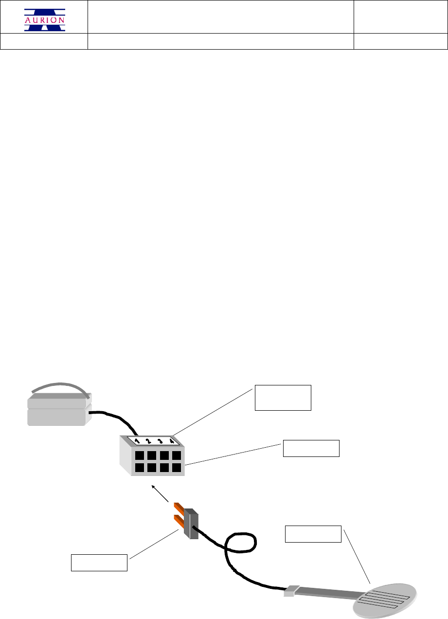
4.8 Piezoresistive sensors
Piezoresistive sensors for the gait cycles events detection are placed under the foot surface, in a position that
allows a precise measurement of support and toe off. Up to four sensors for foot are available, and these are
displaced in the typical positions:
- toe, sensor n. 1
- first metatarsus, sensor n. 2
- fifth metatarsus, sensor n. 3
- heel, sensor n. 4
Sensors are not different from each other and they are numbered from 1 to 4 only to identify the application
area.
The location and the positioning techniques can change according to operator preferences.
The connection to Footswitch electrode has to be done according to the following:
PIEZORESISTIVE
SENSOR
FSW ELECTRODE
SOCKET
FSW SENSOR
PLUG
WHITE LABEL
TOP PART OF THE
SOCKET
USER MANUAL COD. ZW04 REV 10
04/10/05 Pag. 19
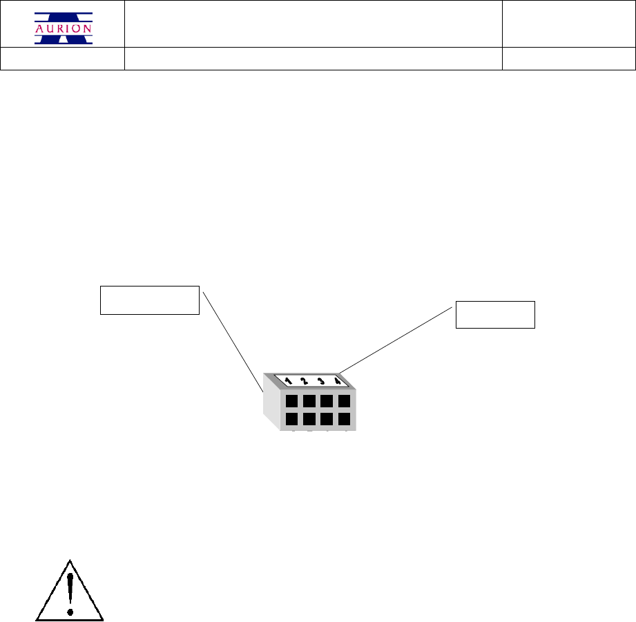
Procede according to the following instructions:
1. apply the sensor on the patient;
2. identify the orientation of the FSW electrode socket;
3. put the FSW sensor plug into the FSW electrode socket according to the number.
The four inputs are electrically and mechanically identical; to have a correct data identification, inputs
are:
TOP PART OF THE
SOCKET
FSW ELECTRODE
SOCKET
The FSW sensor plug isn’t polarised and can be connected in both ways; the FSW electrode socket has
a white coloured label to make easier the numeric assignment of sensors.
If FSW has been wrongly connected, sensors will not work properly, but the system will
not be damaged.
USER MANUAL COD. ZW04 REV 10
04/10/05 Pag. 20
5. SYSTEM MAINTENANCE
5.1 Repairable parts
ZeroWire system doesn’t contain parts repairable by the user; for standard maintenance see the following
chapters.
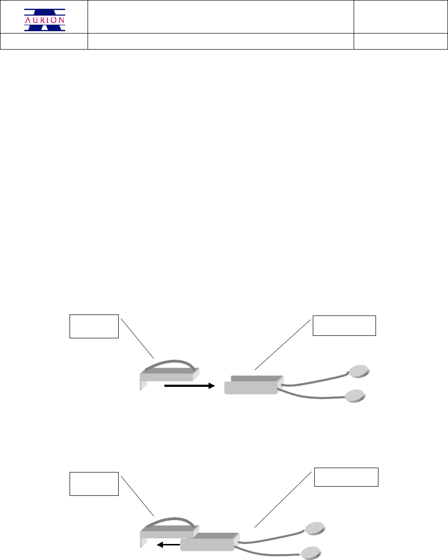
5.2 Replacement of electrode battery
After about 300 charging/discharging cycles, the battery could reduce its electric capacity that leads to
a shorter time of use of the electrodes. To re-enable the normal efficiency, replace the battery module as
follow:
EMG
ACQUISITIONE
MODULE
POWERED EMG
INPUT MODULE
Take off the battery module from the acquisition module applying a small force in the direction of the
arrow.
EMG
ACQUISITIONE
MODULE
FEEDING AND EMG
INPUT MODULE
Put on the new battery module in the acquisition module until they are aligned and you hear a click.
USER MANUAL COD. ZW04 REV 10
04/10/05 Pag. 21
You can find the battery module at:
Aurion S.r.l.
Viale Certosa, 191
20151 Milano
Tel. +39 02 87.387.000
Fax +39 02 33.499.083
e-mail: aurion@aurion.it
The replacement of the powersupply module of the foot-switch electrode is the same.
5.2.1 Module identification
Modules are identified by a label inside of the electrode; to access to labels see the indication in the
previous paragraph.
5.3 Warnings about electrodes battery
Lithium rechargeable battery is inside the power supply module; the replacement made by the user is
not allowed; only the producer can replaces it.
Lithium battery of the power supply module
Warning: DON’T disassemble the battery.
Warning: DON’T short-circuit the battery terminals.
Warning: DON’T cut or drill the battery container; the electrolyte is dangerous for human
body. If you touch the electrolyte, immediately wash the part with water and call a
doctor.
Warning: DON’T burn down or put the battery in the fire.
Warning: DON’T use electrodes with battery that is losing electrolyte, or smells of electrolyte,
or has the container blown up.
USER MANUAL COD. ZW04 REV 10
04/10/05 Pag. 22
Warning: Electrodes that are loosing electrolyte or smells of electrolyte have to be kept away
from fire.
Warning: Check the storing modalities, working and recharging temperature in chapter “Tech-
nical Specifications”
5.4 Warnings for battery disposal
Disposal of the power supply module
The power supply module contains a rechargeable battery; for its disposal observe
local and national limitation for lithium battery.
5.5 Warnings for device disposal
Disposal of the ZeroWire system
Base unit, electrodes and optional of the ZeroWire system have to be disposed off com-
plying with national and local limitation for electronical devices and with European Directive
2002/95/CE, 2002/96/CE, 2003/108/CE.
5.6 Replacement of worn parts
Parts up for wear in ZeroWire system are:
1. terminals and clips of EMG electrodes; check monthly clips and wires; if the wire is worn,
replace the lower EMG module;
2. terminals and clips of foot-switch electrodes; check monthly the connector of piezoresistive
sensors and wires; if the wire is worn, replace the FSW lower module.

USER MANUAL COD. ZW04 REV 10
04/10/05 Pag. 23
5.7 ZeroWire cleaning
To clean ZeroWire system components use a soft cloth damped with neutral soap. System components
are NOT protected by liquid infiltration.
The cleaning of the system elements has to be done:
1. base unit: every six months or more often if required
2. electrodes: every 50 hour or more often if required
Warning:
liquid infiltration can cause the EMG signal amplitude reduction, or the interruption of the electrode
functioning. In these cases, proceed as follow:
- take of the acquisition module (upper part) from the battery module, as described in
“Replacement of electrode battery” chapter;
- remove the liquid with a dry cloth;
- make the modules drying using a low temperature source (thermosiphon or owen at
maximum 30°C);
If the problem holds over, change the electrode.
5.8 References
In the event of non-functioning, breakdown or other problems dealing with ZeroWire system, please
contact:
Aurion S.r.l.
Viale Certosa, 191
20151 Milano
Tel. +39 02 87.387.000
Fax +39 02 33.499.083
e-mail: aurion@aurion.it
or the authorised service:

USER MANUAL COD. ZW04 REV 10
04/10/05 Pag. 24
6. TECHNICAL SPECIFICATIONS
Base unit
Transmission / Reception frequency 2400 – 2524 MHz
Transmission power (ARP) 0,45 mW
Number of channels 125
Power supply voltage 9 Vcc +- 10%
Absorbed power 2 W
Operating temperature range 0 + 50 °C
Input:
Start trigger TTL, max ±10 V
Trigger out TTL
Output:
EMG Output ± 2,5 V, Zout = 100 ohm
FSW Output 16 levels, max 4 V
USB USB 2.0
Gain 1.000 (1V/mV)
Dimension 200 x 140 x 50 mm
Weight 800 gr.
EMG Module
Transmission / Reception frequency 2400 – 2524 MHz
Transmission power (ARP) 0,45 mW
Number of channels 125
Power supply voltage 4 Vcc
Absorbed power 50 uW
Operating temperature range 0 + 50 °C
Using range (charged battery 100%) > 8 h
Stand by range > 180 gg.
EMG input +- 2,5 mV
Filtering High-pass 10 Hz
Low-pass 1 KHz
Sampling rate 16 bit – 2 Ks/sec.
Dimensions 33 x 23 x 19 mm.
Weight 35 gr.

USER MANUAL COD. ZW04 REV 10
04/10/05 Pag. 25
FOOTSWITCHES Module
Transmission / Reception frequency 2400 – 2524 MHz
Transmission power (ARP) 0,45 mW
Number of channels 125
Power supply voltage 4 Vcc
Absorbed power 50 uW
Operating temperature range 0 + 50 °C
Using range (charged battery 100%) > 8 h
Stand by - range > 180 gg.
FSW input for piezoresistive sensors
Dimensions 33 x 23 x 19 mm.
Weight 35 gr.
Docking Module
Recharging capacity 10 modules
Power supply voltage 9 V +- 10%
Maximum absorbed power 7 W
Recharging time 8 h (max. 24h)
Dimension 190 x 110 x 55 mm.
Weight 500 gr.
Net feeding
Power supply voltage 100 – 240 V 50/60 Hz
Output voltage 9 V cc, 1,5 A
Power supply cable 2,1 X 5,5 S 11,5 coax (+ central)
Environmental conditions
Operating temperature 0°C /+45 °C
Electrodes recharging temperature 0°C /+45 °C
Working damp 65 +- 20 % RH
Storing temperature -20°C/ 35°C

USER MANUAL COD. ZW04 REV 10
04/10/05 Pag. 26
6.1 Suitability
For a correct functioning of the radio link between electrodes and base unit, the relative distance has
not to be bigger than ten meters.