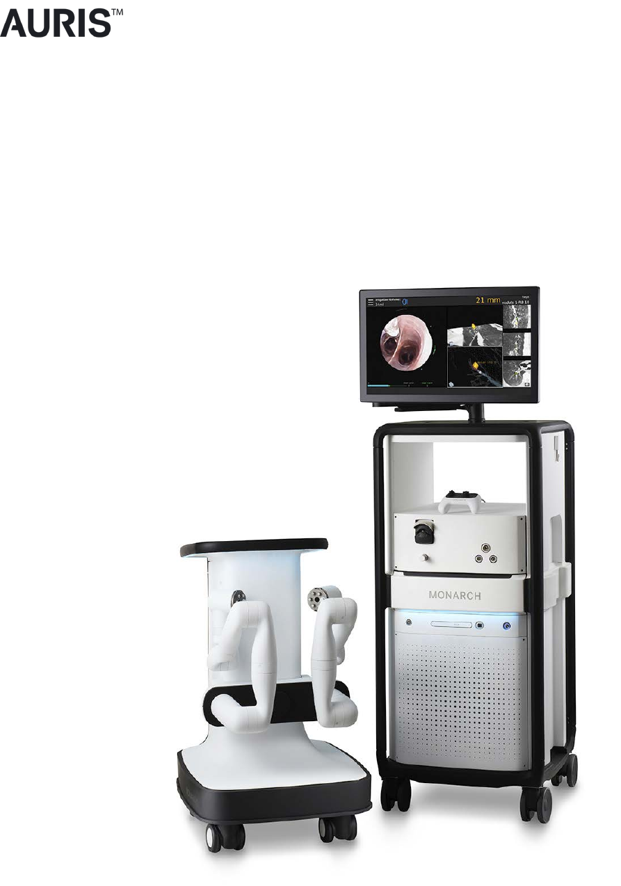
Auris Surgical Robotics MONARCH Monarch Robotic Endoscopy Platform User Manual 300 002547 00
Auris Surgical Robotics Inc. Monarch Robotic Endoscopy Platform 300 002547 00
User Manual
300-002547-00 rev7
MONARCH™ PLATFORM
User Manual
300-002547-00 rev7
300-002547-00 rev7
Monarch™ Platform
User Manual
Date of Last Revision: 2018-05-08

ii 300-002547-00 rev7
Auris Health, Inc. Headquarters and Manufacturing
150 Shoreline Drive
Redwood City, CA 94065
Tel: +1.650.264.6000
Manufacturer Responsible for Placing Products on the Market
Auris Health, Inc.
150 Shoreline Drive
Redwood City, CA 94065
Tel: +1.650.264.6000
Customer Support
Only qualified service personnel should service or maintain hardware components. If you
feel that the Monarch Platform hardware components or associated features or functions
do not perform as expected, or they provide results that are inconsistent with your
established clinical and research protocols, contact Auris Customer Care at
+1.800.434.0032 (toll-free within the United States) or +1.650.264.6000 (Worldwide).
You can also email CustomerCare@AurisHealth.com.
Copyright © 2016-2018 Auris Health, Inc. All rights reserved.
This document, the software and products to which this document refers, and any other
related materials are the copyrighted and proprietary information of Auris Health, Inc.
and may not be used or distributed without written authorization of Auris Health, Inc. No
part of this document may be photocopied, reproduced, or translated into another
language without written permission from Auris Health, Inc.
AURIS, MONARCH, MONARCH READY, and MONARCH ELEVATE are trademarks
and/or registered trademarks of Auris Health, Inc. in the United States and in other
countries and may not be used or distributed without written authorization from Auris
Health, Inc. Use of Auris Health, Inc.’s trademarks require written authorization from
Auris Health, Inc. The following logos are trademarks of Auris Health, Inc.:
300-002547-00 rev7 iii
All other trademarks and product names used herein are the property of their respective
owners. Monarch™ Pre-Op Planning Application and Monarch™ Navigation Application
are distributed on Auris Health, Inc. hardware.
Auris Health, Inc. provides this guide "as is" and "as available" without any warranties,
including, without limitation, warranties of merchantability, fitness for any particular
purpose, title and noninfringement. Auris Health, Inc. expressly excludes and disclaims
such warranties.
To the maximum extent permitted by law, Auris, its suppliers, affiliates, officers,
directors, employees, agents, and assigns will not be liable: (a) for costs of procurement
of substitute goods, technology, or services, lost profits or business opportunities or any
other special, indirect, incidental, consequential or reliance damages arising from any
claim related to this manual or use of Auris’s products discussed herein, however
caused and under any theory of liability, whether based in contract, tort (including
negligence and strict liability) or otherwise; (b) for content or data that is transmitted over
or through Auris’s networks, equipment or systems; (c) for any unavailability, defect,
error, interruption, delay, downtime, loss, or attenuation of services caused by or
resulting from any act or omission by the user of Auris’s products and services; or (d) for
injury, death, or harm of any nature (whether direct or indirect, and whether or not
foreseeable) resulting from (i) materials, equipment or accessories not furnished by
Auris, (ii) lost components, parts, and accessories, (iii) any product which has been
modified, altered, repaired, serviced, or reinstalled by anyone other than Auris or its
authorized representative, (iv) any product stored, used, or handled in any manner
inconsistent with Auris’s trainings and written instructions, or by individuals who have not
been adequately trained on the proper use of the product, (v) any product damaged due
to accident, negligence, misuse, or abnormal use, (vi) any product damaged through no
fault of Auris during shipment, or (vii) damage or failure of a product for which Auris
provided an update or replacement and the damage or failure would not have occurred
but for user’s failure to install such update or replacement (failure to install includes
failure to allow Auris to remotely install security patches and provide preventive and
remedial diagnostic services by connecting the Monarch System to Auris’s proprietary
cloud platform over the internet).
Unauthorized modifications of any Auris products may void any and all warranties. Auris
Health, Inc. does not assume any responsibility or liability with respect to unauthorized
modification or substitution of subsystems or components.
This manual applies to the Monarch™ Platform, Monarch™ Pre-Op Planning Application
2.1.1, and Monarch™ Navigation Application 2.1.1.
Expected Life Statement
With proper care and maintenance, the expected service life of the system is 7 years.

iv 300-002547-00 rev7
Introduction
This manual provides information specific to the Monarch™ Platform, also known as the
Monarch™ Platform. The operating instructions and feature descriptions herein are
specific to the software versions listed on page iii.
NOTE: Anyone who operates, services, maintains, or is otherwise associated with the
Monarch Platform must read, understand, and be thoroughly familiar with the
information in this manual, and take precautions to protect themselves, their
associates, patients, and the equipment. At each step in the installation, specific
warnings and cautions are given for specific actions.
Auris Health, Inc. reserves the right to revise this publication and to make changes in
content from time to time without obligation on the part of Auris Health, Inc. to provide
notification of such revision or change.
Intended Use/Indications for Use
The Monarch™ Endoscopy Platform (Monarch Platform) and its accessories are
intended to provide bronchoscopic visualization of and access to patient airways for
diagnostic and therapeutic procedures.
Contraindications
Contraindications include but are not limited to:
Patient whose general health or respiratory function or both are compromised to the
point that the patient would not tolerate flexible bronchoscopy.
Absence of a trained bronchoscopist to perform or closely and directly supervise the
procedure, as well as manage complications common to flexible bronchoscopy.
Use of the system in patients with electrically or magnetically activated implanted
medical devices.
Warnings
A thorough understanding of the technical principles, clinical applications, and risks
associated with pulmonary bronchoscopy is necessary before using this device.
Additional warnings are detailed throughout this document to describe actions or
conditions that could result in injury or death.
Adverse Effects
Complications from bronchoscopy are rare and most often minor, but if they occur, may
include breathing difficulty, vocal cord spasm, hoarseness, slight fever, vomiting,
dizziness, bronchial spasm, infection, low blood oxygen, bleeding from biopsied site, or
an allergic reaction to medications. Only rarely do patients experience other more

300-002547-00 rev7 v
serious complications (for example, collapsed lung, respiratory failure, heart attack
and/or cardiac arrhythmia).
Prescription Device Statement
CAUTION: Federal law restricts this device to sale by or on the order of a physician.
Safety Precautions and Warnings
Safe operation of the Monarch Platform requires careful attention to the serious hazards
associated with use of the device and ways to avoid or minimize the hazards, and
familiarity with emergency procedures. Untrained or careless operation of the Monarch
Platform can damage the system, its components or other property; cause poor
performance; or lead to serious bodily injury and possibly death.
Auris Health, Inc. strongly recommends that personnel be trained by Auris on the
Monarch Platform prior to use for research or clinical purposes. Only physicians having
adequate training and experience with endoscopic techniques should perform
endoscopic procedures.
Users must follow all instructions for use supplied with the system, its components,
instruments and accessories, including any instructions for use (IFUs) provided with
instruments or accessories. The IFU provided are the primary sources for detailed safety
information.
Under the conditions described in the declaration of immunity section, the system may
fault in an immobilized state. Follow the directions indicated to return to normal
operation.
System Error Messages
Under the error conditions described in Appendix B, all robotic functions are disabled.
Follow the directions indicated to return to normal operation.
Notations
This manual uses the special notations below to bring your attention to important
information.
WARNING: Describes actions or conditions that could result in injury or death.
CAUTION: Describes actions or conditions that could result in damage to the
equipment or minor harm to the user or patient.
NOTE: Provides more information about a subject.

vi 300-002547-00 rev7
Disposal
When an Auris product reaches the end of its useful life and your facility desires to
remove the device, contact Auris Customer Care at +1.800.434.0032 (toll-free within the
United States) or +1.650.264.6000 (Worldwide) to uninstall and appropriately dispose of
the components.
When disposing of instruments, accessories, or any of their components, follow all
applicable national and local laws and guidelines.
Regulatory Compliance with Directives and Standards
The Monarch Platform complies with the regulatory requirements of Directive 2017/745,
the Medical Device Directive of the European Economic Community (EEC).
The Monarch Platform and accessories have been tested for compliance to the following
standards:
Standard Number Standard Title
AAMI/ANSI ES60601-1:2005 (Third
Edition)
Medical electrical equipment - Part 1: General
requirements for basic safety and essential performance
EN 60601-1-2:2007 (Third Edition) Medical electrical equipment - Part 1-2: General
requirements for basic safety and essential performance –
Collateral standard: Electromagnetic compatibility –
Requirements and tests
IEC 60601-1-6:2010 (Third Edition) Medical electrical equipment – Part 1-6: General
requirements for basic safety and essential performance –
Collateral standard: Usability
IEC 60601-2-18:2009 (Third Edition) Medical electrical equipment - Part 2-18: Particular
requirements for the basic safety and essential
performance of endoscopic equipment
IEC 62366:2007 Medical devices -- Application of usability engineering to
medical devices
IEC 62366-1:2015 Medical devices -- Part 1: Application of usability
engineering to medical devices
ISO 15223-1:2016 Medical devices -- Symbols to be used with medical device
labels, labelling and information to be supplied -- Part 1:
General requirements
ISO 14971:2007 Medical devices -- Application of risk management to
medical devices
ISO 11135:2014 Sterilization of health-care products – Ethylene Oxide –
Requirements for the development, validation, and routine
control of a sterilization process for medical devices
ISO 11607-1:2006 Packaging for terminally sterilized medical devices – Part
1: Requirements for materials, sterile barrier systems and
packaging systems

300-002547-00 rev7 vii
Standard Number Standard Title
ISO 11607-2:2006 Packaging for terminally sterilized medical devices – Part
2: Validation requirements for forming, sealing and
assembly processes
ISO 10993-5:2009 Biological evaluation of medical devices -- Part 5: Tests for
in vitro cytotoxicity (Biocompatibility)
ISO 10993-10:2010 Biological evaluation of medical devices -- Part 10: Tests
for irritation and skin sensitization (Biocompatibility)
ISO 10993-11:2006 Biological evaluation of medical devices – Part 11: Tests
for systemic toxicity (Biocompatibility)
ISO 8600-1:2015
Endoscopes -- Medical endoscopes and endotherapy
devices -- Part 1: General requirements
ISO 8600-3:1997 Optics and optical instruments -- Medical endoscopes and
endoscopic accessories -- Part 3: Determination of field of
view and direction of view of endoscopes with optics
ISO 8600-4:2014
Endoscopes -- Medical endoscopes and endotherapy
devices -- Part 4: Determination of maximum width of
insertion portion
BS EN 1041:2008 Information supplied by a manufacturer of medical devices
BS EN 556-1:2001 Sterilization of medical devices - Requirements for medical
devices to be designated ""STERILE"" – Part 1:
Requirements for terminally sterilized medical devices"
ANSI/AAMI/ISO 14937:2009 Sterilization of health care products -- General
requirements for characterization of a sterilizing agent and
the development, validation and routine control of a
sterilization process for medical devices
CSA 22.2 NO 60601-1:14 Medical Electrical Equipment, Part 1: General
requirements for basic safety and essential performance
FCC ID: 2AOXMMonarch
NOTE: This equipment has been tested and found to comply with the limits for a Class
A digital device, pursuant to part 15 of the FCC Rules. These limits are designed to
provide reasonable protection against harmful interference when the equipment is
operated in a commercial environment. This equipment generates, uses, and can
radiate radio frequency energy and, if not installed and used in accordance with the
instruction manual, may cause harmful interference to radio communications.
Operation of this equipment in a residential area is likely to cause harmful interference
in which case the user will be required to correct the interference at his own expense.
viii 300-002547-00 rev7
300-002547-00 rev7 ix
x 300-002547-00 rev7
Contents
............................................................. 1
Monarch Platform Device Overview ............................................................................ 2
System Overview ........................................................................................................ 3
Pre-Procedural Planning ....................................................................................... 3
Monarch Cart ......................................................................................................... 3
Monarch Tower ..................................................................................................... 7
Monarch Bronchoscope System ........................................................................... 9
Working Channel Instruments ............................................................................. 10
Accessories ......................................................................................................... 10
Classifications ........................................................................................................... 11
Monarch Platform Labels .......................................................................................... 12
Label Locations ................................................................................................... 15
Technical Specifications ............................................................................................ 16
Physical Dimensions, Weight, and Power Requirements .................................... 16
Declaration of Emissions ........................................................................................... 17
Declaration of Immunity ............................................................................................. 19
Original Documentation ............................................................................................. 22
................................................................................................ 23
Recommended CT Scan and Reconstruction Parameters ....................................... 24
Monarch Pre-Op Planning Application User Interface ............................................... 26
Patient List ........................................................................................................... 26
Planning .............................................................................................................. 29
Manual Path ........................................................................................................ 32
Before You Can Plan ................................................................................................. 33
Create a Plan ............................................................................................................ 33
Identify a Target .................................................................................................. 35
Export a Patient Case ............................................................................................... 37
Import a Patient Case ................................................................................................ 38
300-002547-00 rev7 xi
Perform an Unplanned Case ..................................................................................... 38
............................................................................................................ 39
Software Information ................................................................................................. 40
Suggested Bronchoscopy Suite Configuration .......................................................... 40
Prepare the Bronchoscopy Suite ............................................................................... 41
Prepare the Patient ................................................................................................... 41
Prepare the Monarch Bronchoscope System ............................................................ 43
Monarch Tower System Setup Guidance .................................................................. 44
Monarch Controller .............................................................................................. 44
Fluidics System ................................................................................................... 45
Camera ................................................................................................................ 46
Navigation ........................................................................................................... 46
Monarch Cart System Setup Guidance ..................................................................... 48
Unstow Cart ......................................................................................................... 48
Load the Monarch Bronchoscope System ........................................................... 51
............................................................................................ 53
Overview ................................................................................................................... 54
Functional Descriptions of Monarch Components ..................................................... 54
Monarch Bronchoscope and Monarch Bronchoscope Sheath ............................ 54
Monarch Controller .............................................................................................. 55
Working Channel Instruments ................................................................................... 57
Monarch Navigation Application User Interface ........................................................ 58
Top Navigation Bar .............................................................................................. 60
Primary Area ....................................................................................................... 60
Scrolling Area ...................................................................................................... 61
CT Area ............................................................................................................... 62
Full Screen Mode ................................................................................................ 63
Menu System ...................................................................................................... 63
Navigation Views ................................................................................................. 65
Configuring View Screens ................................................................................... 75
Quick Action Button ............................................................................................. 77

xii 300-002547-00 rev7
Procedural Steps or Actions ...................................................................................... 78
Scope Insertion ................................................................................................... 78
Navigation Initialization ........................................................................................ 79
Monarch Bronchoscope Advancement ............................................................... 79
Perform Biopsy .......................................................................................................... 80
Monarch Controller .............................................................................................. 80
Post-procedure .......................................................................................................... 81
Retraction ............................................................................................................ 81
........................................................................ 83
Prepare the Patient for Discharge ............................................................................. 84
Remove the Monarch Bronchoscope System ..................................................... 84
Remove Monarch Navigation Patient Sensors .................................................... 84
Remove the Bronchoscope Patient Introducer .................................................... 84
Remove and Clean Equipment ................................................................................. 84
Disassemble and Clean the Monarch Bronchoscope System ............................. 84
Clean Monarch Navigation Patient Sensors ........................................................ 85
Disassemble and Clean the Monarch Navigation Field Generator ...................... 86
Disassemble and Clean Bronchoscope Patient Introducer Mount ...................... 86
Clean and Store the Monarch Cart ...................................................................... 86
Clean the Monarch Tower and Store the Monarch Platform ............................... 86
Servicing .................................................................................................................... 87
Preventative Maintenance ................................................................................... 87
Configuration ....................................................................................................... 87
Maintenance ........................................................................................................ 87
............................................................................... 91
User Administration ................................................................................................... 92
User Types .......................................................................................................... 92
Add New User ..................................................................................................... 92
Change User Password ...................................................................................... 93
Disable Existing User .......................................................................................... 94

300-002547-00 rev7 xiii
System Security ........................................................................................................ 95
Virus Protection ................................................................................................... 95
Patient Data Security ........................................................................................... 95
Networking ................................................................................................................ 95
Firewall ................................................................................................................ 95
Internet Connectivity ............................................................................................ 95
...................................................................................................... 97
Fault Messages and Troubleshooting ....................................................................... 98
Emergency Removal ........................................................................................... 98
E-Stop Recovery ................................................................................................. 98
Joystick Articulations Not Matching Directionally ................................................ 98
Controller Does Not Appear Functional ............................................................... 98
Field Generator or Patient Introducer Mount Clamps Do Not Tighten ................. 99
Monarch Platform Will Not Turn On..................................................................... 99
Tower and Cart Do Not Turn On Simultaneously ................................................ 99
Video (Start Screen) Does Not Appear on Tower and Cart Monitor After System
Turns On ........................................................................................................... 100
Loss of Video on Tower or Cart Touchscreen (During Procedure) ................... 100
Navigation Patient Sensors Not Detected During Setup ................................... 100
CT Scan or Pre-Planned Case Cannot be Uploaded to Tower ......................... 101
Keyboard on Planning Laptop Is Unresponsive ................................................ 101
Planning Laptop Will Not Turn on ...................................................................... 101
Unable to log on to Physician User Account on Tower or Planning Laptop ...... 101
Unable to log on to Admin User Account on Tower or Planning Laptop ........... 101
................................................................................................................................ 103
Errors and Messages ................................................................................................................ 103
System Messages ................................................................................................... 104
xiv 300-002547-00 rev7

300-002547-00 rev7
Safety Information and Technical
Description
This chapter provides information that is essential for the safe operation, transport, and
storage of the Monarch Platform.
Monarch Platform Device Overview ............................................................................ 2
System Overview ........................................................................................................ 3
Classifications ........................................................................................................... 11
Monarch Platform Labels .......................................................................................... 12
Technical Specifications ............................................................................................ 16
Declaration of Emissions ........................................................................................... 17
Declaration of Immunity ............................................................................................. 19
Original Documentation ............................................................................................. 22
CAUTION: Do not modify this equipment. Modification of this equipment may result in
injury to users or patients and may void product warranties.
Installation of this system is to be performed only by an authorized Auris representative.
There are no user serviceable components. Contact Auris Customer Care at
+1.800.434.0032 (toll-free within the United States) or +1.650.264.6000 (Worldwide) to
schedule installation or service.

2 300-002547-00 rev7
Monarch Platform Device Overview
This user manual refers to the Monarch Platform and the associated components
used with it. Refer to the following table for a list of products.
Official Product Name Shortened Name
Monarch™ Platform
Monarch™ Pre-Op Planning Application Planning Application
Monarch™ Pre-Op Planning System Planning System
Monarch™ Tower Tower
Monarch™ Cart Cart
Monarch™ Controller Controller
Monarch™ Touchscreen Touchscreen
Monarch™ Navigation Application Navigation App
Monarch™ Bronchoscope System Bronchoscope System (consists of both the
Bronchoscope and Sheath)
Monarch™ Bronchoscope Bronchoscope
Monarch™ Bronchoscope Sheath Sheath
Aspirating Biopsy Needle Needle
Bronchoscope Patient Introducer Mount Patient Introducer Mount
Bronchoscope Patient Introducer Patient Introducer
Monarch™ Navigation Field Generator Field Generator
Monarch™ Navigation Field Generator Mount Field Generator Mount
Monarch™ Navigation Patient Sensors Patient Sensors
Navigation Patient Patches Patient Patches
Bronchoscope Swivel Adapter Swivel Adapter
Bronchoscope Fluidics Tubing Fluidics Tubing
Bronchoscope Sheath Valve Sheath Valve
Instrument Device Manipulators IDM

300-002547-00 rev7 3
System Overview
The Monarch Platform enables electro-mechanical articulation and precise
control of a flexible endoscope (bronchoscope) under continuous and direct
control by a physician operator. The Monarch Platform includes fused navigation
that integrates a pre-operative computed tomography scan into an intra-operative
interface displaying endoscope tip location relative to the pre-operative scan
anatomy.
Pre-Procedural Planning
Prior to the procedure, the Monarch Pre-Op Planning Application running on the
Monarch Pre-Op Planning System or Monarch Tower Touchscreen enables a
physician to review a pre-procedural CT scan and plan a pathway through the
airways for a physician-controlled bronchoscope to navigate towards the target of
interest. During the procedure, the software integrates a pre-procedural CT scan
into a user interface.
The Monarch Pre-Op Planning Application provides the following features:
• CT viewing capabilities similar to standard CT DICOM viewer software.
• Airway segmentation: segmentation of the trachea and main airways to aid
visualization of the airways and path planning.
• Target identification: ability to select one or more targets of interest.
• Path planning: computer generated path to the target based on segmented
airways.
• Manual path planning: ability for user to identify airways and modify the path
on the CT scan to finalize a pathway to the target as necessary.
Monarch Pre-Op Planning Application is accessible from both the Monarch
Tower Touchscreen and the Monarch Pre-Op Planning System.
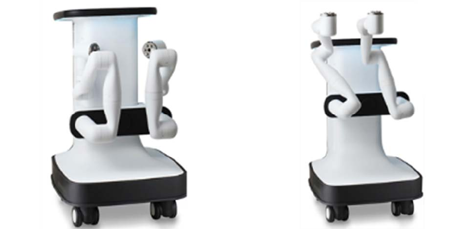
Monarch Cart
The Monarch Cart is a maneuverable piece of capital equipment that can be
transported in and out of the bronchoscopy suite, stowed away when not in use,
and positioned relative to the patient table as needed for a given procedure. It is
used to transmit physician controls to the Monarch Bronchoscope System
(insertion, retraction, and articulation). It contains a Touchscreen monitor, two
robotic arms, and mating robotic Instrument Device Manipulators (IDM) which are
mountable, robotic interfaces for the bronchoscope.
4 300-002547-00 rev7
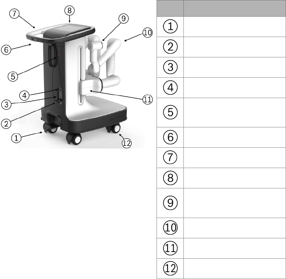
The following image shows the Monarch Cart with the robotic arms in the stow
position (left) and load Bronchoscope System position (right):
The Monarch Cart is a carrier for the robot arms. It includes two robotic arms
which contain rotary pulleys to actuate the drive cables in the Monarch
Bronchoscope System. The cart houses the electronic systems required to power
and operate the robot arms.
300-002547-00 rev7 5
Item Description
Foot pedal
Power cable
Umbilical port
Power button
Emergency stop button
(E-stop)
Cart directional lock switch
Cart handle
Cart Touchscreen
Instrument Device Manipulator
(IDM)
Robotic arm
Vertical lift
Immobilization feet (not shown)
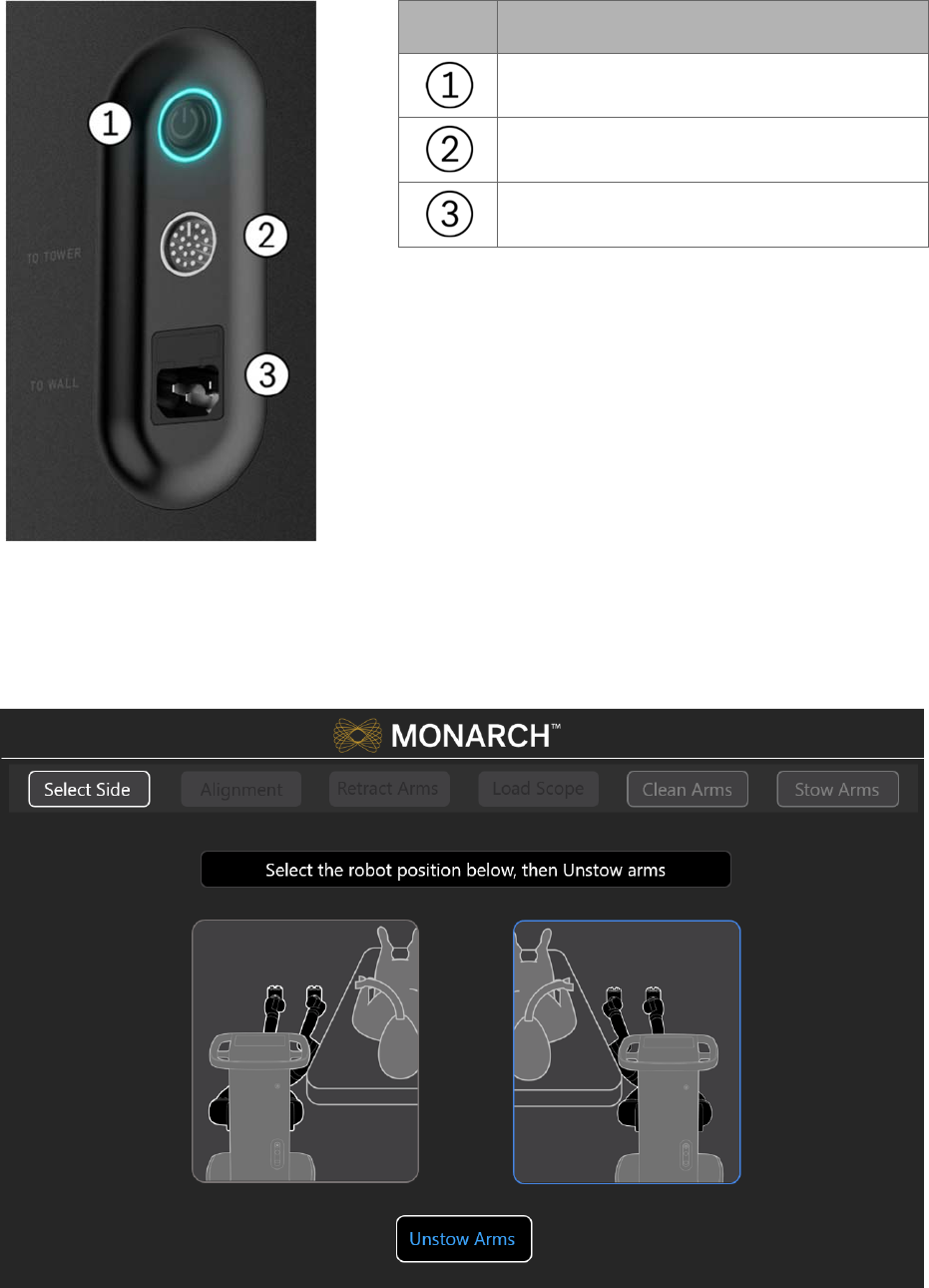
6 300-002547-00 rev7
Item Description
Power button
Umbilical port to the Monarch Tower
Power cord plug
Automated lift controls will raise and lower the height of the robotic arms based
on your control. The cart handle allows the cart to be directionally locked for ease
of maneuverability. An embedded Touchscreen on the cart handle provides
system setup instructions and allows user input, as shown in the following image.
300-002547-00 rev7 7
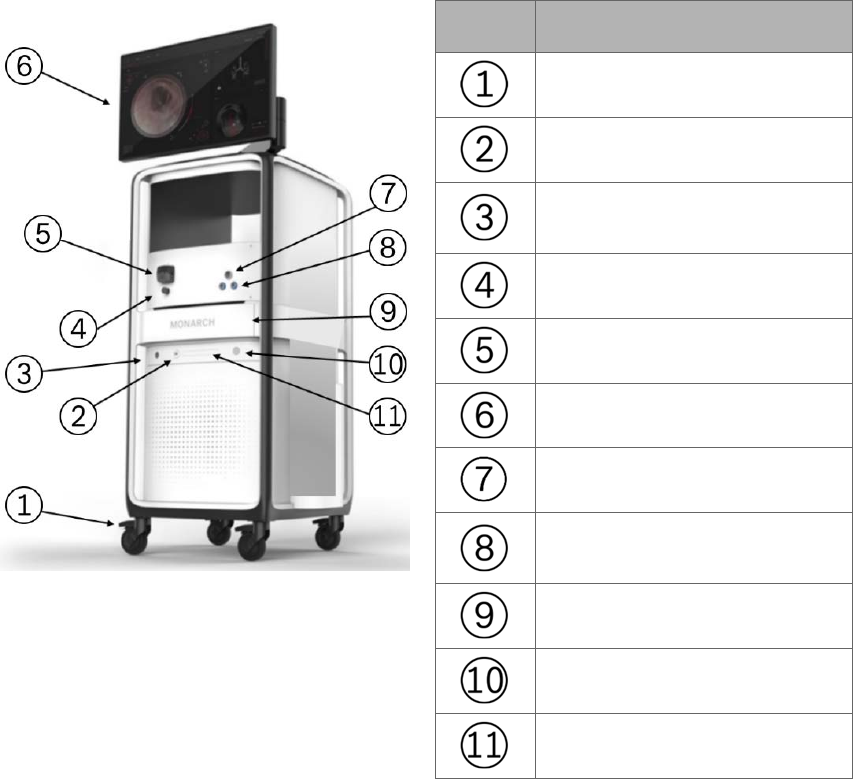
Monarch Tower
The Monarch Tower is a maneuverable piece of capital equipment that can be
transported in and out of the bronchoscopy suite and stowed away when not in
use. It is the primary physician procedural display interface. It contains a monitor
for physician viewing and computers running the Monarch Bronchoscopy Tower
Software, the Monarch Navigation Application, which displays real time video
captured from the Monarch Bronchoscope camera overlaid with information on
the status of the Monarch Platform and the Monarch Pre-Op Planning
Application. The tower also provides connectivity for the Monarch Bronchoscope
camera and lighting, as well as the fluidics system. The fluidics system has an
integrated pump and pinch valve to control irrigation and aspiration respectively.
The monitor is Touchscreen for physician input during setup, planning, and
procedure.
The following images shows the tower:
Item Description
Caster lock
USB port
Monarch Navigation Field
Generator port
Pinch valve
Peristaltic pump
Monarch Touchscreen
Bronchoscope umbilical port
Monarch Navigation Patient
Sensors port
Drawer
Power button
Optical disc drive (DVD)
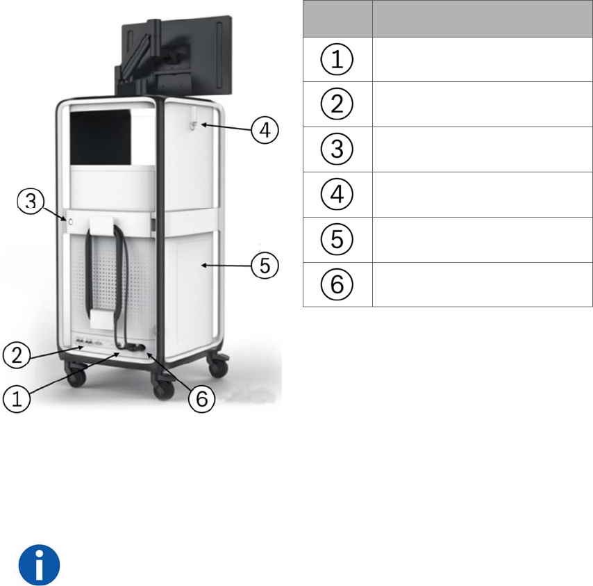
8 300-002547-00 rev7
Item Description
Power cable
Video ports
Service door lock
Hook
Side storage door
Umbilical cable
The following components are included in the Monarch Tower: non-real-time
computer, real-time computer, endoscopic controller, camera, Monarch
Navigation Field Generator and power distribution unit (PDU) box. The PDU
contains the power supply to the tower only, as well as the batteries and UPS
which provide auxiliary power in the event of system fault.
NOTE: The Monarch Platform incorporates an uninterruptible power supply
backup. In the event of a power outage, the backup supply provides a five-minute
operating window, which allows the operator to safely remove the Monarch
Bronchoscope System and shut down the Monarch Platform.
The tower includes the Monarch Controller that allows the clinician to control the
system during a procedure. Two joysticks are used to drive and articulate the
Monarch Bronchoscope while various buttons are used to control irrigation,
aspiration, Tower user interface, light, bronchoscope/sheath selection, and image
capture.
300-002547-00 rev7 9
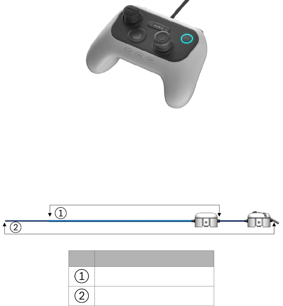
The following image shows the Monarch Controller:
Monarch Bronchoscope System
The Monarch Bronchoscope System is comprised of two collinear and concentric
devices, the inner Monarch Bronchoscope and the outer Monarch Bronchoscope
Sheath, both of which possess 4-way steering control. This configuration enables
the capability of telescoping, which enhances the Monarch Bronchoscope
System stability and access capability.
The following figure images show the Monarch Bronchoscope System and the
handles:
Item Equipment
Monarch Bronchoscope Sheath
Monarch Bronchoscope
The Monarch Bronchoscope includes a camera that provides the operative
perspective, an integrated light source in the handle, and a 2.1mm inner diameter
working channel for the passing of manually controlled tools.
The Monarch Bronchoscope System has a distal section capable of achieving
articulation in any direction and any combination of the two to enable precise
control while driving the Monarch Bronchoscope.
The Fluidics Tubing is equipped
10 300-002547-00 rev7
with a valve at the end
to facilitate the insertion and sealing of various ancillary
devices, such as the Aspirating Biopsy Needle. Additionally, the proximal section
routes irrigation and aspiration to the shared working channel.
Working Channel Instruments
The following single-use manually controlled Auris instruments compatible with
the Monarch Platform are provided sterilized: Aspirating Biopsy Needle, Biopsy
Forceps, and Cytology Brush. Refer to individual Instructions for Use included
with each working channel instrument for additional information.
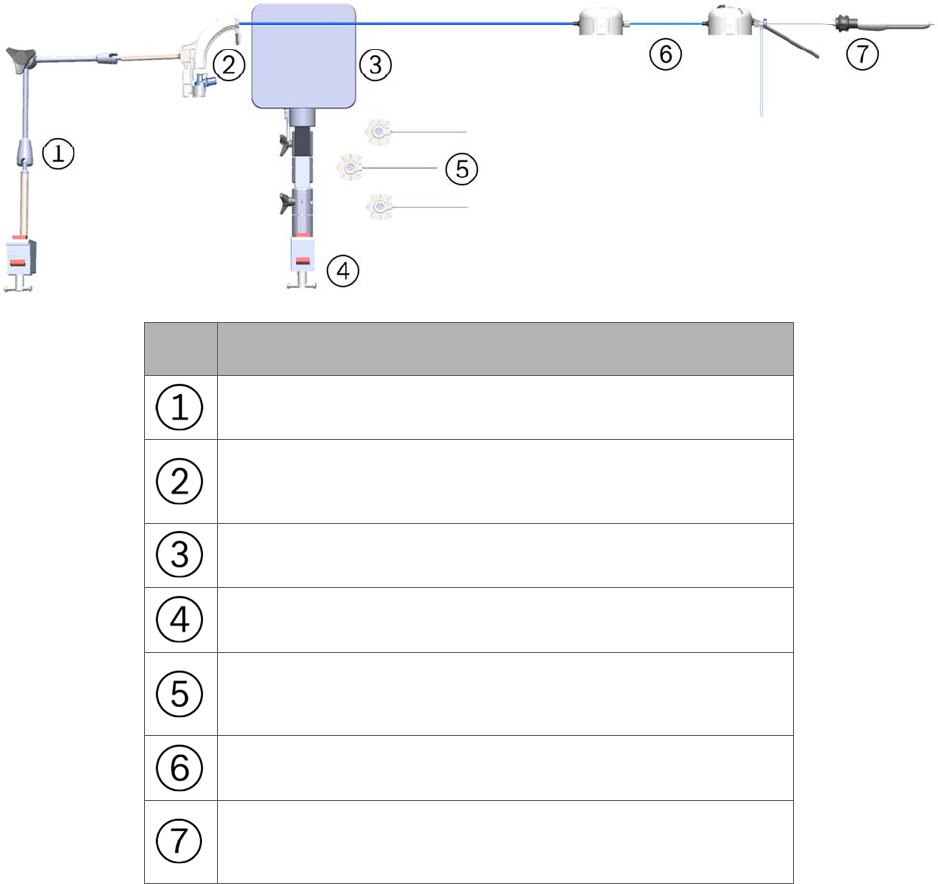
Accessories
Item Equipment
Bronchoscope Patient Introducer Mount
Bronchoscope Patient Introducer with Bronchoscope
Swivel Adapter
Monarch Navigation Field Generator
Monarch Navigation Field Generator Mount
Monarch Navigation Patient Sensors and single-use
Navigation Patient Patches
Monarch Bronchoscope System and Sheath Valve
Working channel instrument (needle shown) inserted
through Fluidics Tubing valve

300-002547-00 rev7 11
Disposable Accessories
The system features sterilized single-use accessories necessary to perform
bronchoscopic procedures. These accessories are:
Bronchoscope Patient Introducer: A tube that guides the Bronchoscope
System through the Bronchoscope Swivel Adapter and into the endotracheal
tube.
Bronchoscope Swivel Adapter: Standard bronchoscope accessory that
attaches to the endotracheal tube to allow passage of a bronchoscope while
maintaining ventilation pressure. It is packaged with the Bronchoscope
Patient Introducer.
Bronchoscope Fluidics Tubing: Separate tubing lines for saline irrigation and
vacuum aspiration which converge at a valve that attaches to the
bronchoscope working channel. Saline irrigation and aspiration lines connect
to the tower. A valve is connected to the end of the Bronchoscope Fluidics
Tubing and provides a means of introducing working channel instruments,
irrigation, and aspiration into the working channel.
Bronchoscope Sheath Valve: Attaches to the proximal hub of the sheath and
provides a seal around the bronchoscope to reduce ventilation leakage.
Navigation Patient Patches: Single-use disposable adhesive patches that are
used to attach the Monarch Navigation Patient Sensors to the patient’s chest.
The patches are not provided sterile.
Non-Disposable Accessories
The following non-disposable accessories are included and stored with the tower.
Bronchoscope Patient Introducer Mount: Adjustable mount that attaches to a
bed rail and holds the Bronchoscope Patient Introducer.
Monarch Navigation Patient Sensors: Attaches to the patient to provide an
estimate of patient positioning for alignment of the Monarch Navigation Field
Generator.
Monarch Navigation Field Generator: Provides an electromagnetic field to be
sensed by scope and patient sensors to provide locational information. The
Monarch Navigation Field Generator plugs into the Monarch Tower.
Monarch Navigation Field Generator Mount: Adjustable mounts that attaches
to a bed rail and holds the Monarch Navigation Field Generator.
Classifications
According to Directive 2017/745, this product is a Class IIa Medical Device.
According to CISPR 11 (a publication of the IEC committee on radio
interference), this product is Group 1, Class A ISM Equipment.
12 300-002547-00 rev7
The Monarch Platform is classified by the following:
Protection against electric shock: Class 1 (grounded equipment).
Applied part(s): All Applied Parts of the Monarch System are Type BF Applied
Parts.
Protection against harmful ingress of water: Rated IPX0 (ordinary equipment,
not specially protected).
Methods of sterilization or disinfection: Ethylene oxide processing.
Mode of operation: The Monarch System is considered Continuous
equipment as defined by IEC 60601-1.
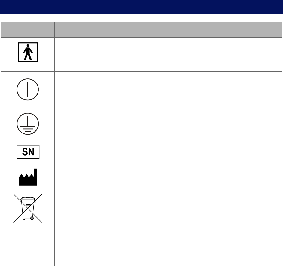
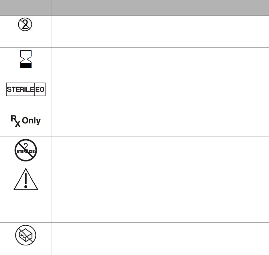
Monarch Platform Labels
Symbol Name Meaning
Type BF applied part
symbol is in accordance
with IEC 60601-1.
Used to indicate Type BF certified components.
ON/OFF This indicates the power on state of the system.
This power switch does not isolate the mains
supply.
Protective Earth This indicates a protective earth (grounding)
terminal.
Manufacturer’s Serial
Number
This symbol appears adjacent to the
manufacturer’s serial number.
Equipment Manufacturer
and date of Manufacture
This symbol appears adjacent to the name and
address of the equipment manufacturer.
Waste Electrical and
Electrical Equipment
This symbol indicates that this equipment has
been designed as electrical and electronic
equipment that is not to be disposed of as
unsorted municipal waste. EEE contains
substances that may present hazards to human
and to the environment. It must be recovered,
reused, recycled, or otherwise treated, and
properly disposed of.
300-002547-00 rev7 13
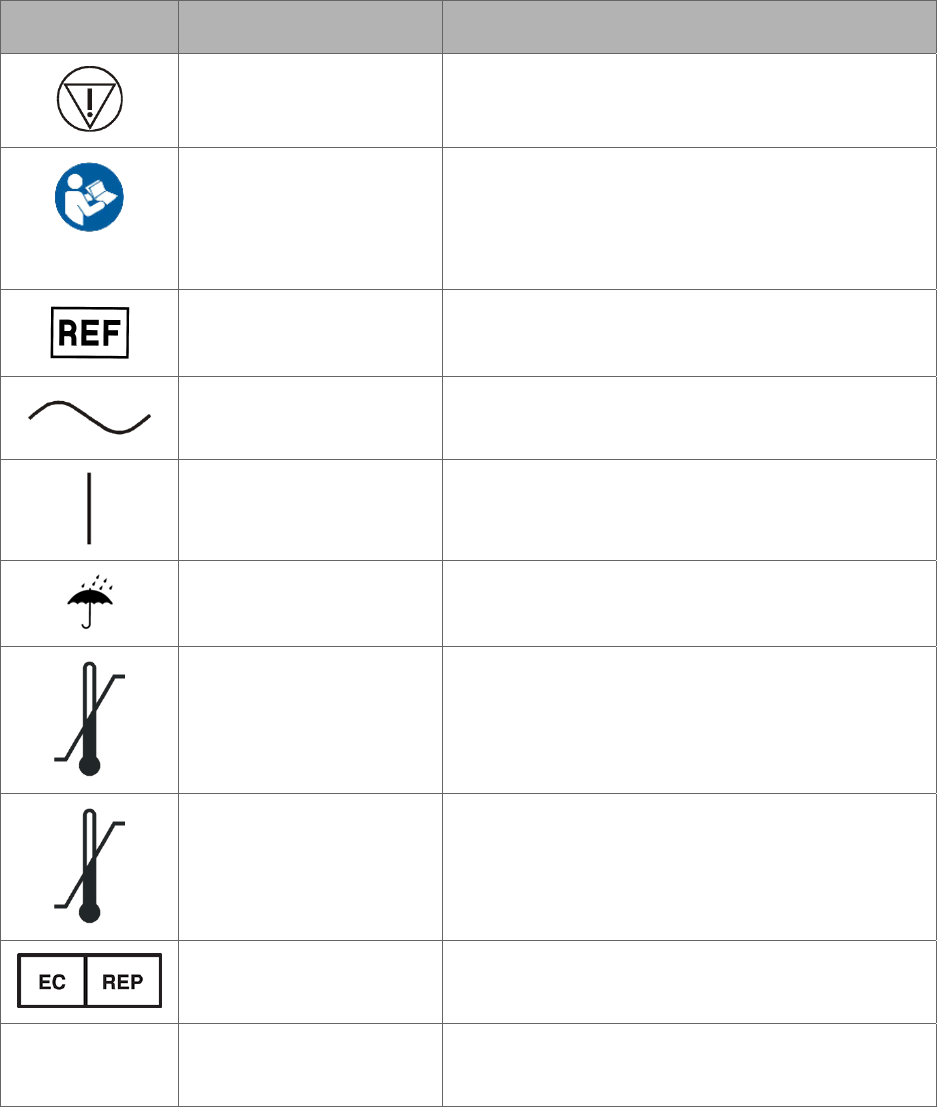
Symbol Name Meaning
Emergency Stop This symbol indicates an emergency stop
control device.
Read instructions prior
to use
This symbol is used to alert the user to refer to
the user manual or other instructions when
complete information cannot be provided on the
label.
Reference Number This symbol appears adjacent to Catalog or
Assembly Number.
Alternating Current This symbol indicates that the equipment is
suitable for alternating current only.
ON This symbol indicates connection to the mains.
Keep dry This symbol indicates to store in a dry place.
Temperature limit 10°C
to 25°C
This symbol indicates the operating temperature
limits of the device.
Temperature limit -25°C
to 70°C
This symbol indicates the non-operating
temperature limits of the device.
Authorized EU
Representative
This symbol indicates the name and address of
authorized EU representative.
IPX0
No special protection
against water
This symbol indicates the degree of protection
the device has against the ingress of water.
14 300-002547-00 rev7
Symbol Name Meaning
Single-use only Used to warn the user that the piece of
equipment with this label is for single-use only
and it must not be used more than once.
Use by date This symbol indicates that the device should not
be used after the date accompanying the
symbol.
Sterilized using ethylene
oxide
This symbol indicates that the device is
provided sterile and has been sterilized using
ethylene oxide.
Rx only Federal (USA) law restricts this device to sale
by or on the order of a physician.
Do not re-sterilize This symbol indicates that the device should not
be re-sterilized after it once has been sterilized.
Caution This symbol indicates that caution is necessary
when operating the device or control close to
where the symbol is placed, or to indicate that
the current situation needs operator awareness
or operator action in order to avoid undesirable
consequences.
Do not use if package is
damaged
This symbol indicates that the device must not
be used if the package holding the device is
damaged.
300-002547-00 rev7 15
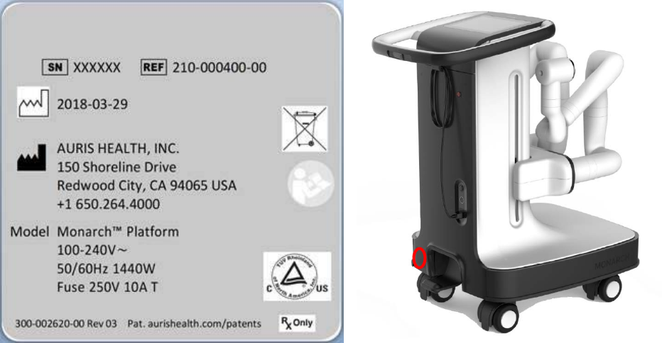
Label Locations
The following figures show the system labels and their locations. The Monarch
System UDI is located on the tower.
Cart
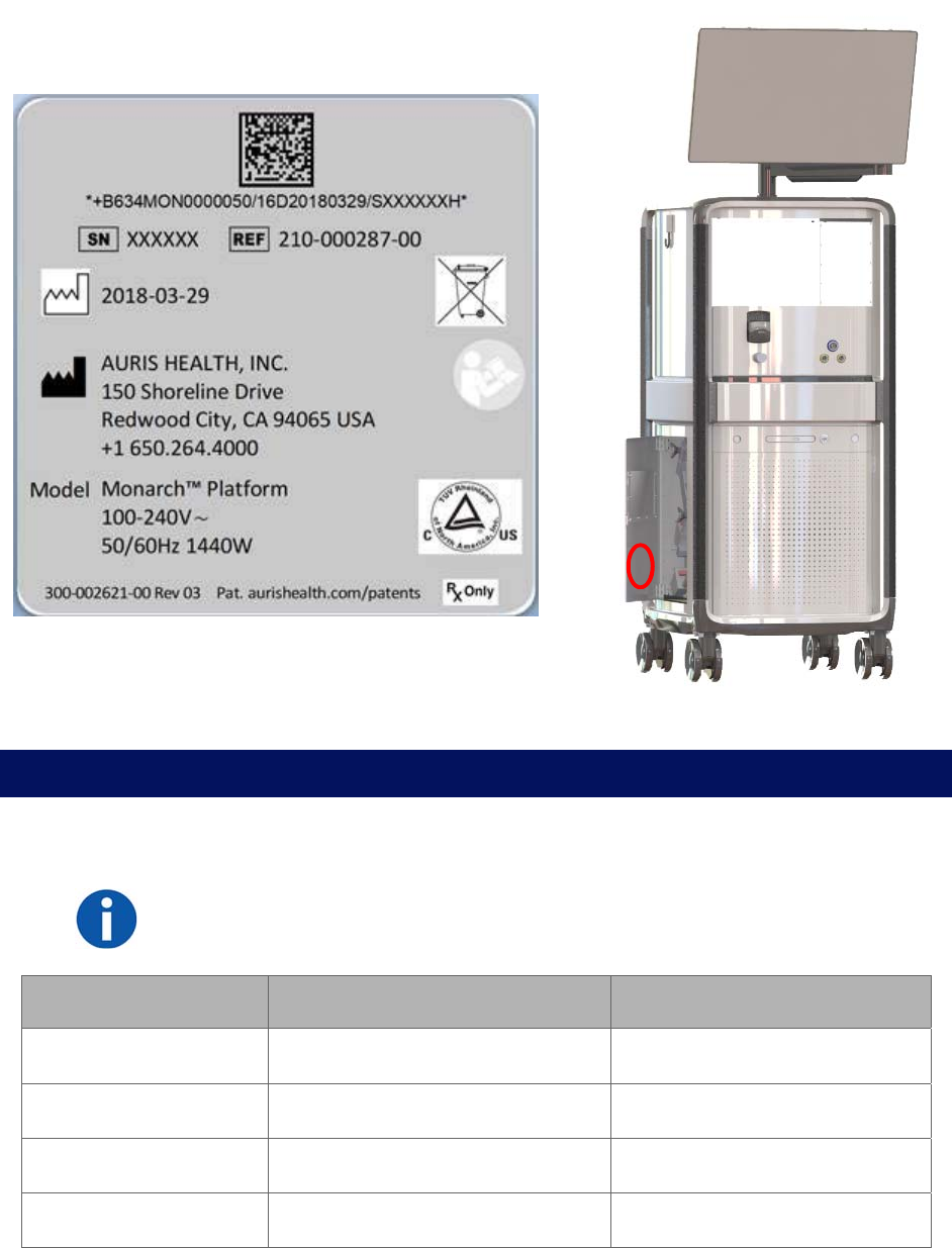
16 300-002547-00 rev7
Tower
Technical Specifications
Physical Dimensions, Weight, and Power Requirements
NOTE: AC power cord is mains disconnect device.
Subsystem Monarch Tower Monarch Cart
Height 66.4”/168.7 cm 39.8”/101.1 cm
Width 24.7”/62.8 cm 23.9”/60.7 cm
Depth 29”/73.6 cm 34”/86.4 cm
Weight (maximum) 892 lb/405 kg 785 lb/356.4 kg

300-002547-00 rev7 17
Subsystem Monarch Tower Monarch Cart
Max weight on shelf 25 kg
Power Requirement 100-240V~ 50/60Hz 1440W* 100-240V~ 50/60Hz 1000W*
*Requires separate dedicated branch circuits.
The Monarch Platform should be transported, stored, and used in the following
environmental conditions:
Monarch Platform Operating Non-Operating
(Storage or Shipment)
Temperature 10° C to 25° C -25° C to 70° C
Humidity 30% to 60% Non-condensing 10% to 85% Non-condensing
Noise Generated 63 dB @ 1 meter & 20° C NA
Altitude Up to 3000 meters N/A
Declaration of Emissions
To comply with the regulations on electromagnetic interference for a Class A
FCC Device, all interconnect cables to external devices (for example, monitors)
must be shielded and properly grounded. Use of cables not properly shielded
and grounded may result in the equipment causing radio frequency interference
in violation of the FCC regulations.
All types of electronic equipment may characteristically cause electromagnetic
interference with other equipment, either transmitted through air or connecting
cables. The term EMC (Electromagnetic Compatibility) indicates the capability of
equipment to curb electromagnetic influence from other equipment and at the
same time not affect other equipment with similar electromagnetic radiation from
itself.
Proper installation is required in order to achieve the full EMC performance of the
product. Operate the system with all covers closed. Operating the system with
any cover open may affect EMC performance.
The Monarch Platform may be used safely while connected to other devices if
the devices and their specifications, installation, and interconnection with the
system conform to the requirements of IEC 60601-1 (3rd Edition) or IEC 60601-1-
1(2nd Edition). This system is suitable for use in the following environment. The
user must assure that it is used only in the electromagnetic environment as
specified.

18 300-002547-00 rev7
Table 1. Guidance and Manufacturer’s Declaration – Electromagnetic Emissions – For All ME
Equipment and ME Systems
Guidance and Manufacturer’s Declaration – Electromagnetic Emissions
The ME System is intended for use in the electromagnetic environment specified below. The
customer or the user of the ME System should assure that it is used in such an environment.
Emissions Test Compliance Electromagnetic Environment - Guidance
RF emissions
CISPR 11
Group 1 The ME System uses RF energy only for its
internal function. Therefore, its RF emissions are
very low and are not likely to cause any
interference in nearby electronic equipment.
RF emissions
CISPR 11
Class A The ME System is suitable for use in all
establishments other than domestic, and may be
used in domestic establishments and those
directly connected to the public low-voltage power
supply network that supplies buildings used for
domestic purposes, provided the following
warning is heeded:
Warning: This equipment/system is intended for
use by healthcare professionals only. This
equipment/ system may cause radio interference
or may disrupt the operation of nearby equipment.
It may be necessary to take mitigation measures,
such as re-orienting or relocating the ME System
or shielding the location.
Harmonic
emissions
IEC 61000-3-2
Class A
Voltage
fluctuations/
flicker emissions
IEC 61000-3-3
Complies

300-002547-00 rev7 19
Declaration of Immunity
The Monarch Platform is to be used per the specified guidance and only in the
electromagnetic environment listed below.
Table 2. Guidance and Manufacturer’s Declaration – Electromagnetic Immunity – For All ME
EQUIPMENT and ME SYSTEMS
Guidance and Manufacturer’s Declaration – Electromagnetic Immunity
The ME System is intended for use in the electromagnetic environment specified below. The
customer or the user of the ME System should assure that it is used in such an environment.
Immunity Test IEC 60601 Test
Level
Compliance
Level
Electromagnetic Environment –
Guidance
Electrostatic
discharge (ESD)
IEC 61000-4-2
± 6 kV contact
± 8 kV air
± 6 kV contact
± 8 kV air
Floors should be wood, concrete or
ceramic tile. If floors are covered with
synthetic material, the relative
humidity should be at least 30%.
Electrical fast
transient/burst
IEC 61000-4-4
± 2 kV for power
supply lines
± 1 kV for input/
output lines
± 2 kV for power
supply lines
± 1 kV for input/
output lines
Mains power quality should be that of
a typical commercial or hospital
environment.
During an electrical fast transient
event, the system may fault in the
"Image Frozen" or "Robot Controller
Error" states as described in
Appendix B.
Surge
IEC 61000-4-5
± 1 kV line(s) to
line(s)
± 2 kV line(s) to
earth
± 1 kV line(s) to
line(s)
± 2 kV line(s) to
earth
Mains power quality should be that of
a typical commercial or hospital
environment.
During a surge event, the system
may fault in the "Image Frozen" or
"Robot Controller Error" states as
described in Appendix B.

20 300-002547-00 rev7
Immunity Test IEC 60601 Test
Level
Compliance
Level
Electromagnetic Environment –
Guidance
Voltage dips,
short
interruptions and
voltage
variations on
power supply
input lines
IEC 61000-4-11
<5 % UT
(>95 % dip in UT)
for 0,5 cycle
40 % UT
(60 % dip in UT) for
5 cycles
70 % UT
(30 % dip in UT) for
25 cycles
<5 % UT
(>95 % dip in UT)
for 5 s
5 % UT
(>95 % dip in UT)
for 0,5 cycle
40 % UT
(60 % dip in UT) for
5 cycles
70 % UT
(30 % dip in UT) for
25 cycles
<5 % UT
(>95 % dip in UT)
for 5 s
Mains power quality should be that of
a typical commercial or hospital
environment. If the user of the ME
System requires continued operation
during power mains interruptions, it is
recommended that the ME System
be powered from an uninterruptible
power supply or a battery.
Power frequency
(50/60 Hz)
magnetic field
IEC 61000-4-8
3 A/m 3 A/m Power frequency magnetic fields
should be at levels characteristic of a
typical location in a typical
commercial or hospital environment.
NOTE: UT is the a.c. mains voltage prior to application of the test level.
Table 3. Guidance and Manufacturer’s Declaration – Electromagnetic Immunity – For ME
Equipment and ME Systems That Are Not Life-supporting
Guidance and Manufacturer’s Declaration – Electromagnetic Immunity
The ME System is intended for use in the electromagnetic environment specified below. The
customer or the user of the ME System should assure that it is used in such an environment.
Immunity Test IEC 60601
Test Level
Compliance
Level
Electromagnetic Environment –
Guidance
Conducted RF
IEC 61000-4-6
3 Vrms
150 kHz to 80
MHz
[V1] V Portable and mobile RF
communications equipment should be
used no closer to any part of the ME
System, including cables, than the
recommended separation distance
calculated from the equation applicable
to the frequency of the transmitter.
Radiated RF
IEC 61000-4-3
3 V/m [E1] V/m
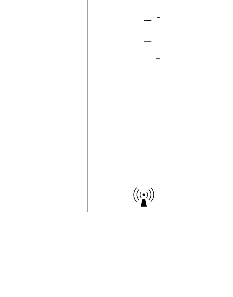
300-002547-00 rev7 21
80 MHz to 2,5
GHz Recommended separation distance
𝑑
3,5
𝑉
√𝑃
𝑑
3,5
𝐸√𝑃 80 MHz to 800 MHz
𝑑7
𝐸√𝑃 800 MHz to 2,5 GHz
where P is the maximum output power
rating of the transmitter in watts (W)
according to the transmitter
manufacturer and d is the
recommended separation distance in
meters (m).
Field strengths from fixed RF
transmitters, as determined by an
electromagnetic site survey,a should be
less than the compliance level in each
frequency range.b
Interference may occur in the vicinity of
equipment marked with the following
symbol:
NOTE 1: At 80 MHz and 800 MHz, the higher frequency range applies.
NOTE 2: These guidelines may not apply in all situations. Electromagnetic propagation is affected by
absorption and reflection from structures, objects and people.
a Field strengths from fixed transmitters, such as base stations for radio (cellular/cordless) telephones
and land mobile radios, amateur radio, AM and FM radio broadcast and TV broadcast cannot be
predicted theoretically with accuracy. To assess the electromagnetic environment due to fixed RF
transmitters, an electromagnetic site survey should be considered. If the measured field strength in
the location in which the ME Systems is used exceeds the applicable RF compliance level above, the
ME Systems should be observed to verify normal operation. If abnormal performance is observed,
additional measures may be necessary, such as re-orienting or relocating the ME Systems.
b Over the frequency range 150 kHz to 80 MHz, field strengths should be less than [V1] V/m.

22 300-002547-00 rev7
Table 4. Recommended separation distances between portable and mobile RF communications
equipment and the ME Equipment or ME System – for ME Equipment and ME Systems that are not
Life-supporting
Recommended Separation Distances Between Portable and Mobile RF
Communications Equipment and the ME System
The ME System is intended for use in an electromagnetic environment in which radiated RF
disturbances are controlled. The customer or the user of the ME System can help prevent
electromagnetic interference by maintaining a minimum distance between portable and
mobile RF communications equipment (transmitters) and the ME System as recommended
below, according to the maximum output power of the communications equipment.
Rated maximum output
power of transmitter
W
Separation distance according to frequency of transmitter
m
150 kHz to 80 MHz
𝑑
3,5
𝑉
√𝑃
80 MHz to 800 MHz
𝑑
3,5
𝐸√𝑃
800 MHz to 2,5 GHz
𝑑7
𝐸√𝑃
0.01 0.12 0.12 0.23
0.1 0.38 0.38 0.73
1 1.2 1.2 2.3
10 3.8 3.8 7.3
100 12 12 23
For transmitters rated at a maximum output power not listed above, the recommended separation
distance d in meters (m) can be estimated using the equation applicable to the frequency of the
transmitter, where P is the maximum output power rating of the transmitter in watts (W) according to
the transmitter manufacturer.
NOTE 1: At 80 MHz and 800 MHz, the separation distance for the higher frequency range applies.
NOTE 2: These guidelines may not apply in all situations. Electromagnetic propagation is affected by
absorption and reflection from structures, objects and people.
These guidelines may not apply in all situations. Electromagnetic propagation is
affected by absorption and reflection from structures, objects, and people.
Original Documentation
This manual is originally written in English.

300-002547-00 rev7 23
Planning a Procedure
Prior to starting the procedure, the Monarch Pre-Op Planning Application is available on
both the Monarch Pre-Op Planning System and Monarch Tower to create a patient case
that contains DICOM and planning data. You can export files to be transferred between
the tower and laptop. Files must be approved before you can export.
Recommended CT Scan and Reconstruction Parameters ....................................... 24
Monarch Pre-Op Planning Application User Interface ............................................... 26
Export a Patient Case ............................................................................................... 37
Import a Patient Case ................................................................................................ 38
Perform an Unplanned Case ..................................................................................... 38

24 300-002547-00 rev7
Recommended CT Scan and Reconstruction Parameters
In order to produce CT images suitable for use with the Monarch Pre-Op
Planning Application and the Monarch Navigation Application, the following
conditions should be met while scanning the patient:
Patient position: Supine, immobile, full inspiration breath hold, arms at
sides.
Scanner type: Multi-slice, 4 detector or greater (16 detector or greater
preferred).
Scan type: Chest, lung, or pulmonary embolism.
Scan area: Entire chest.
Scan duration: Within breath-hold duration of patient.
Image noise: Minimize noise standard deviation.
3D Map generation has been optimized for use with the reconstruction
parameters listed below. 3D Map generation and quality has not been optimized
with other reconstruction parameters, so it is strongly recommended that these
parameters be used.
Image resolution: 512 x 512.
Overlap: 20% – 50%.
Field of view: Minimal field required to cover at least 1cm of trachea and
entire lung volume.
Maximum images: 690.
The following table lists the slice thickness, slice interval, kernel, and filter to use
for each scanner manufacturer:
Scanner
Manufacturer
Slice Thickness
(mm)
Slice Interval
(mm) Kernel and Filter
GE™ 1.25 1.0 Kernel
Filter
Standard
Body
Philips™ 1.0 0.8 Kernel
Enhancement
C
0
Siemens™ 1.0 0.8 Kernel B31f
Toshiba™ 1.0 0.8 Kernel FC05

300-002547-00 rev7 25
The following table lists the slice thickness and slice interval for a 50% and 20%
overlap:
Slice
Thickness (mm)
Minimum Slice Interval (mm)
(at 50% Overlap)
Maximum Slice Interval (mm)
(at 20% Overlap)
1.0 0.5 0.8
1.25 0.625 1.0
1.5 0.75 1.2
2.0 1.00 1.6
2.5 1.25 2.0
3.0 1.50 2.4
4.0 2.00 3.2
5.0 2.50 4.0
NOTE: Overlap % = 100 x (thickness - interval) / thickness.
NOTE: To avoid excess CT noise, the patient should be immobile for the duration
of the scan. For the best 3D Map results, ensure the CT scan is taken with the
patient’s breath held on inspiration.
NOTE: CT scans must be in DICOM format. The DVD format must be UDF
version 1.02 to 2.60. Verify the disk content when the DVD is created to ensure
the disk is valid before attempting to use the disk with the Monarch Pre-Op
Planning Application.
The Monarch Pre-Op Planning Application will not load the PET portion of a
PET/CT scan.
26 300-002547-00 rev7
Monarch Pre-Op Planning Application User Interface
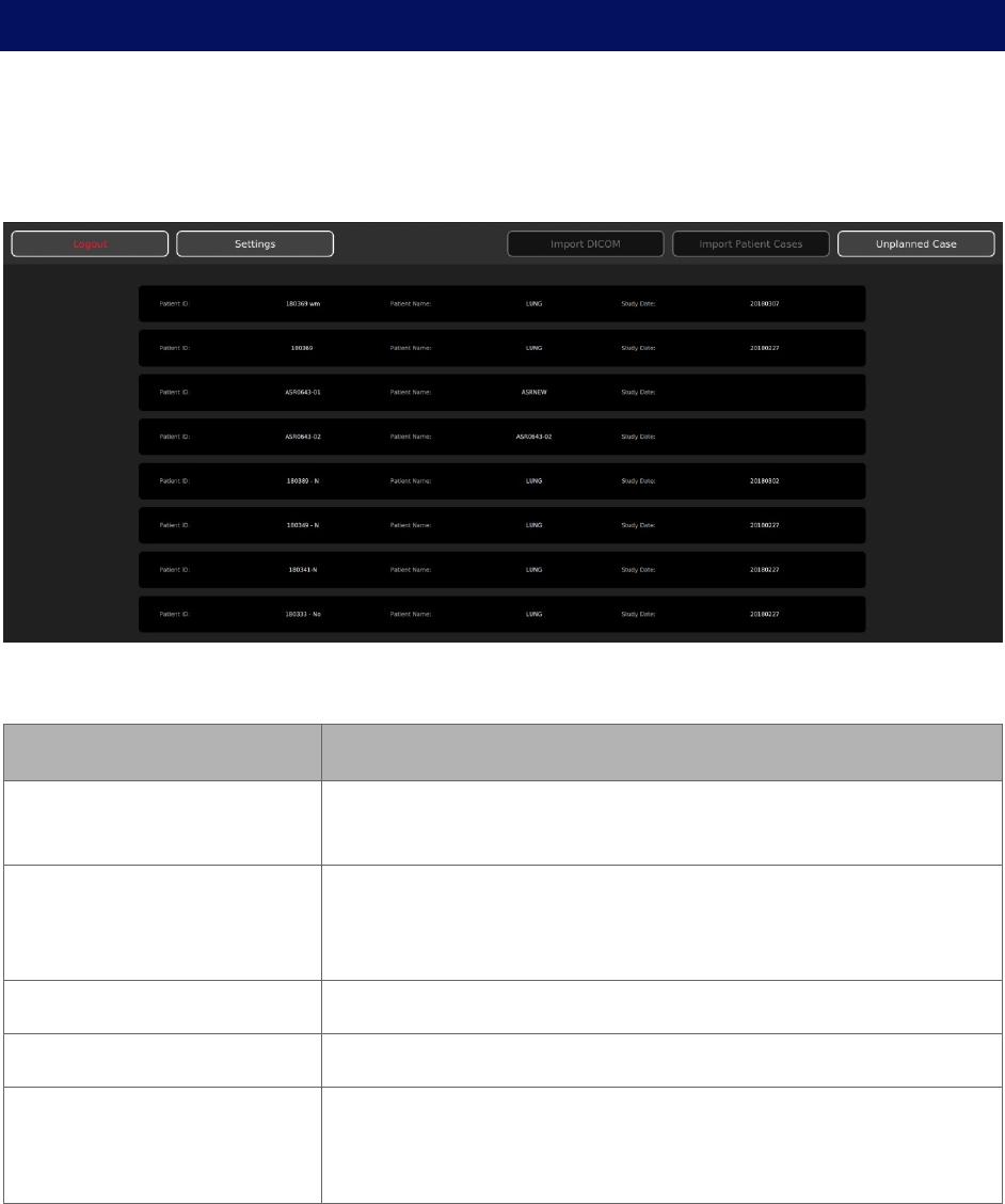
When you log on to the Monarch Pre-Op Planning Application, the Patient List
appears.
Patient List
Patient List Menu
Item Description
Logout Click or tap to log off from the Monarch Pre-Op Planning
Application.
Settings Click or tap to update password, add users, and administrative
settings. For more information, see User Administration (page
92).
Import DICOM Click or tap to import the patient’s CT images.
Import Patient Cases Click or tap to import patient cases.
Unplanned Case Click or tap to create an unplanned case and use the Monarch
Bronchoscope System as bronchoscope without the use of
navigation.
300-002547-00 rev7 27
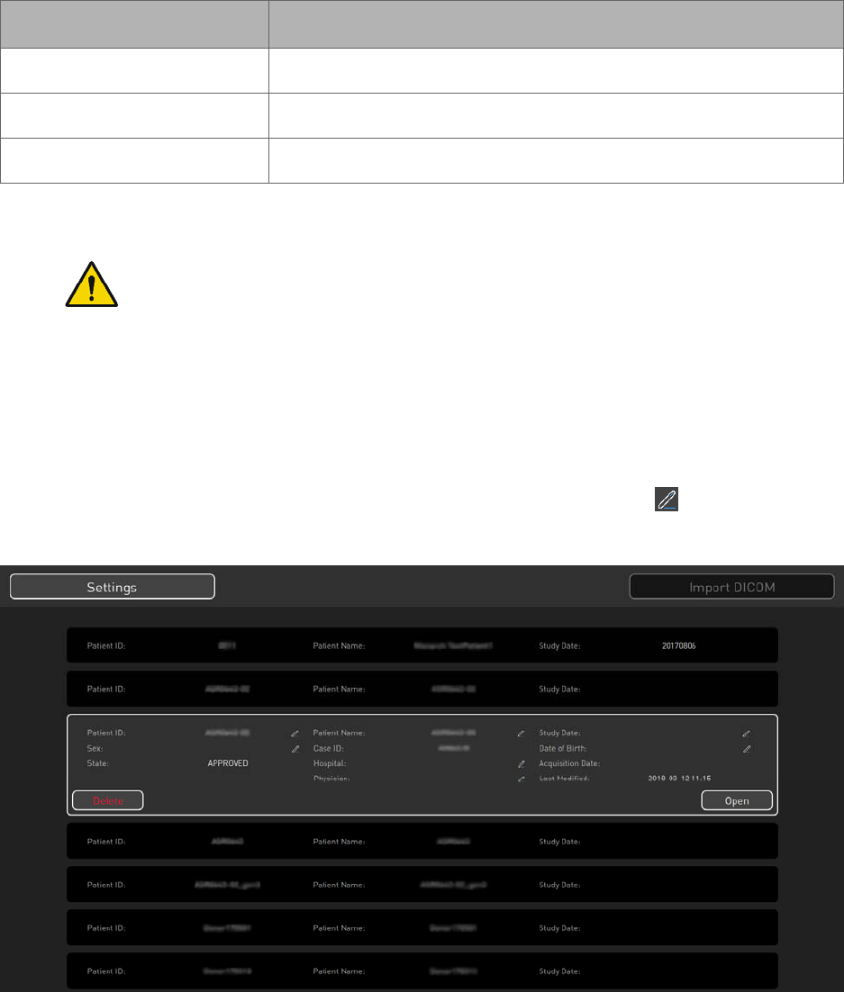
General Patient Information
The Patient List displays the following general patient information.
Item Description
Patient ID Displays the patient’s ID.
Patient Name Displays the patient’s name.
Study Date Displays the date of the study.
Selected Patient Information
WARNING: Entering data in the wrong patient case can result in planning
errors, which may lead to serious injury. To prevent these planning errors:
Make sure you select the correct patient case for the patient.
Verify that the patient information associated with the selected case
identifies the patient you are planning to treat.
Verify that you have selected the correct patient case by reviewing
additional patient information, such as sex and date of birth.
When you select a patient from the list, additional information associated with the
patient appears. To edit any patient information, click or tap if available.

28 300-002547-00 rev7
Item Description
Patient ID Displays the patient’s ID.
Patient Name Displays the patient’s name.
Study Date Displays the date of the study.
Sex Displays the patient’s sex.
Case ID Displays the case ID associated with the selected patient.
Date of Birth Displays the patient’s date of birth.
State Displays the current planning status of the patient case.
NO_SEG: Segmentation has not yet been performed.
SEG_DONE: Status after initial completion of
segmentation.
SEG_ACCEPTED: Patient case has been segmented and
planning has stared, but case is not approved.
APPROVED: Patient case has been approved
Hospital Displays the hospital where the procedure is being performed.
Acquisition Date Displays the acquisition date of the patient’s CTs.
State Change Date Displays the last change date to the patient case’s state.
Physician Displays the name of the physician who planned the patient
case.
Delete Click or tap to delete the selected patient case.
Open Click or tap to open the selected patient case to view.
300-002547-00 rev7 29
Planning
Patient Information
Item Description
Patient ID Displays the patient’s ID.
Patient Name Displays the patient’s name.
Date of Birth Displays the patient’s date of birth.
Hospital Displays the hospital where the procedure is being performed.
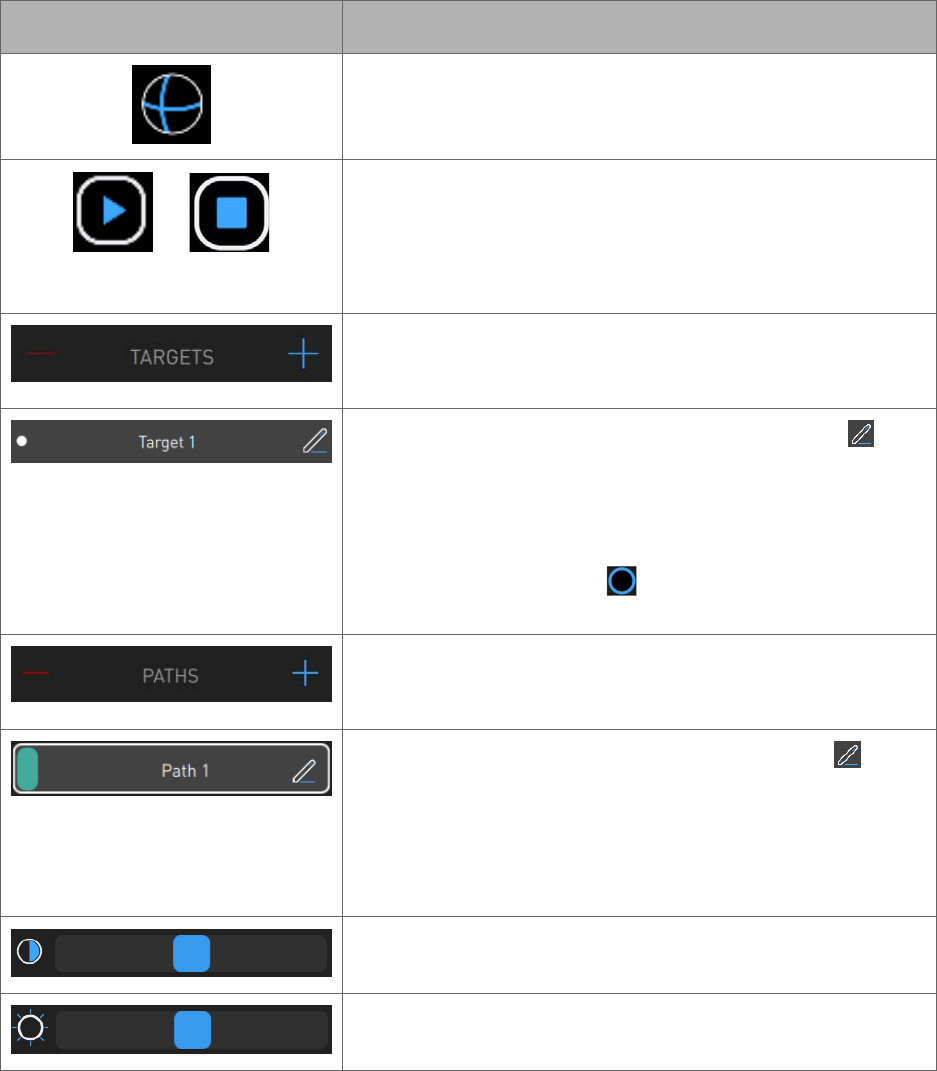
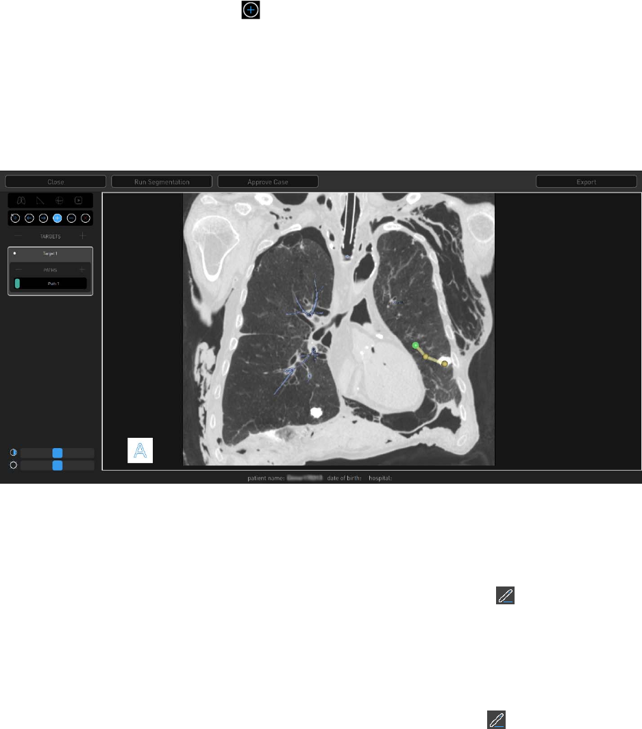
Tools
Item Description
Click or tap to add an overlay of an axial CT image on the
airway tree in Segmentation view.
Click or tap the Manual Path icon to create a manual path
from target to segmented airways.
30 300-002547-00 rev7
Item Description
Click or tap to change the boundary box and highlighted
target anatomy to a sphere.
Click or tap to create a virtual “fly-through” video from the
trachea to the target along the path. While the video plays,
the play icon changes to a stop icon.
Click or tap the icon to stop the video.
Click or tap + to create a new target.
Click or tap – to delete a target.
To change the name of the new target, click or tap and
enter a new target name.
The white dot indicates that the target is the primary target
and is selected by default when starting a case.
The blue-ringed black dot indicates that the target is
non-primary.
Click or tap + to create a new path.
Click or tap - to delete a path.
To change the name of the new path, click or tap and
enter a new path name.
The number in the upper-left corner of the new path
segmentation represents the order of the path in relation to
the procedure.
Use the Contrast slider to adjust the image contrast.
Use the Brightness slider to adjust the image brightness.
300-002547-00 rev7 31
Item Description
A boundary box can be resized in any of the three 3 CT
images. To adjust the outer boundaries of the target, drag
a sizing handle away from or toward the center until the
desired size is reached. The image is adjusted in all three
CT images when updates are made in one image.
The boundary box can be moved without changing the
size by selecting the red ball in the center of the box (not
shown).
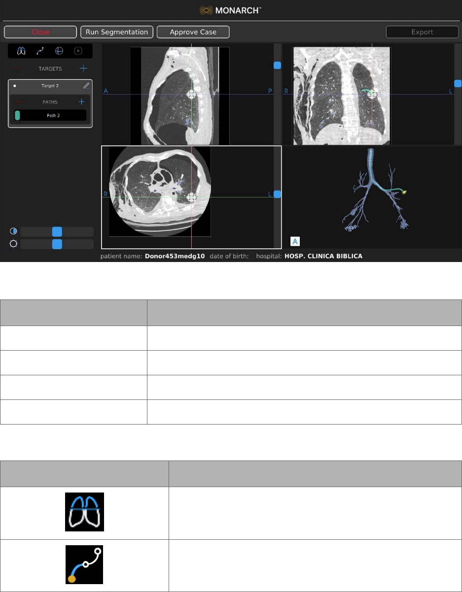
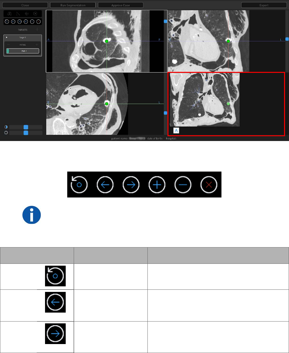
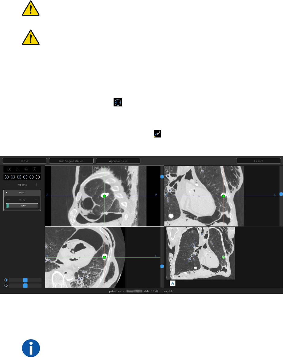
Image Viewers
The image viewers display the CT images and the 3D model from the patient
case.
Planning Menu
Item Description
Close Click or tap to close the current plan.
Run Segmentation Click or tap to run or re-run a segmentation.
Approve Case Click or tap to approve the current plan.
Export Click or tap to export to plan to a Monarch USB drive.
32 300-002547-00 rev7
Manual Path
Manual plans begin at the weighted center of the target and work towards the
main airways. The green ball represents the weighted center of the target.
The lower-right image viewer is the Segmentation view.
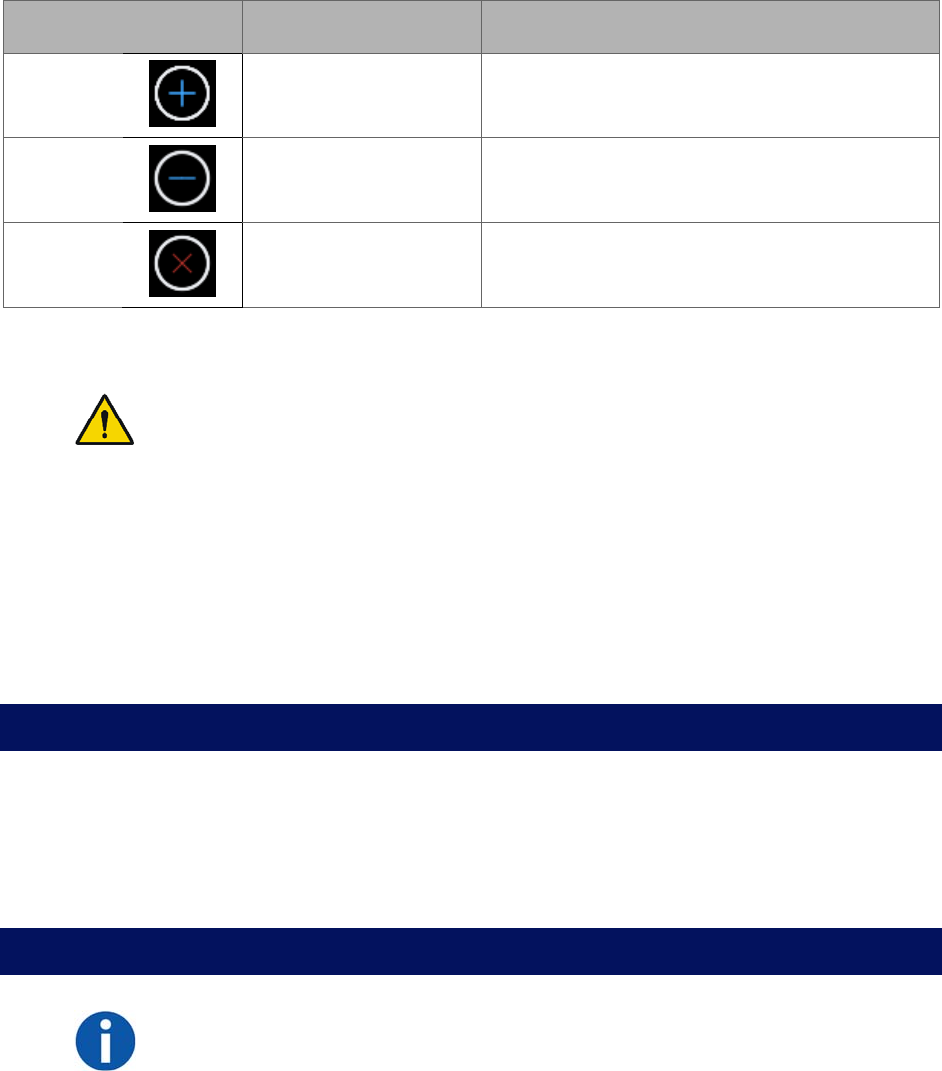
Manual Path Menu
NOTE: All points are deleted if the manual path does not reach the segmented
area.
Use the scroll wheel to zoom and press the scroll wheel button to pan.
Touchscreen Item Mouse Action Description
Reset
N/A Resets to the original segmentation path
information.
Previous
Scroll up in any of the
CT image viewers.
Using either Previous or Next allows you to
re-center the manual path view to the
previous or next point that you have set.
Next
Scroll down in any of
the CT image
viewers.
Using either Previous or Next allows you to
re-center the manual path view to the
previous or next point that you have set.
300-002547-00 rev7 33
Touchscreen Item Mouse Action Description
Add
Click a point in the
segmentation screen.
Add multiple points to create a manual path.
Delete
N/A Deletes a point that you inserted.
Close
Click Close. Exits the Manual Path screen.
Segmentation Review
WARNING: Ensure that the segmentation generated from the CT scan
accurately identifies the airways. Poor segmentation representation may result
in incorrect navigational guidance. Failure to exercise clinical judgment and
endoscopic view to determine appropriate navigation and biopsy plan may
result in biopsy of unintended location.
Automatic Path Adjustments
Any auto generated path can be manually adjusted or manipulated by selecting
and dragging the automatic path to the new location where segmentation exists.
This can be performed in the Segmentation Review screen only.
Before You Can Plan
1. Prior to planning, the patient you are working with is required to be CT
scanned. Refer to the Recommended CT Scan and Reconstruction
Parameters (page 24) for optimal results.
2. Save CT scan to disk.
Create a Plan
NOTE: Multiple CT scans will result in multiple patient cases for the same patient.
1. Log on to the Monarch Pre-Op Planning Application.
2. Click or tap Import DICOM. The DICOM loads from the disk and creates a
new Patient Case from this.
3. Click or tap the patient case to expand the menu and show additional patient
and CT Data information. CT Data includes spacing between slices, slice
thickness, and number of slices for the patient case.
34 300-002547-00 rev7
4. Click or tap the patient DICOM and the select Import.
The new case automatically loads, and the Planning screen appears.
5. Click or tap a patient from the list and select Open. The Planning screen
appears.
6. Double-click or double-tap for a full screen view of any of the image view
windows. Segmentation automatically begins.
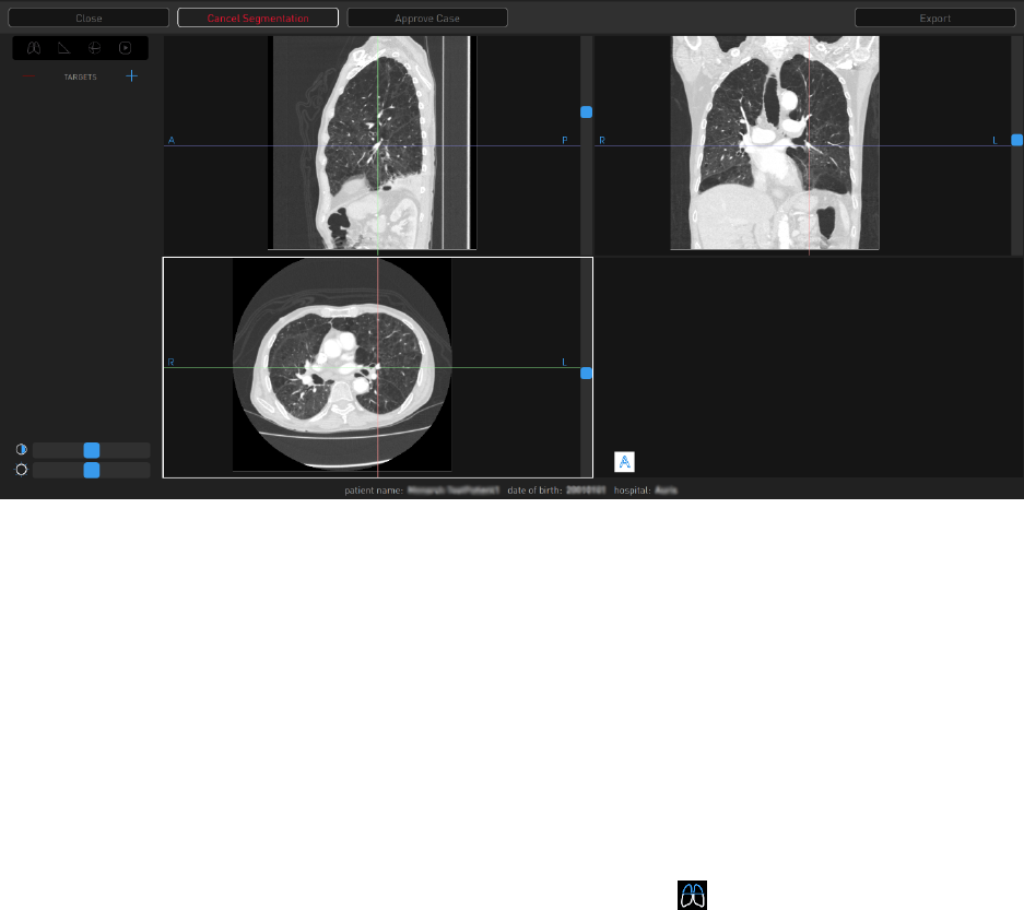
7. Click or tap Cancel Segmentation to stop.
The progress bar inside Cancel Segmentation indicates that "Segmentation"
is proceeding. When segmentation is complete, the status bar updates and
the segmented airway tree appears in the lower-right image viewer
(Segmentation view).
8. Review the segmentation results.
a. If you do not like the segmentation results, click or tap Run
Segmentation.
9. An overlay of an axial CT slice can be added to the segmented airway tree in
Segmentation view by clicking or tapping the icon. The axial slice overlay
correlates to the section of the segmented airway selected.
a. Click or tap another section of the segmented airway tree to move the
overlaid CT slice.
300-002547-00 rev7 35
Identify a Target
WARNING: Increased size of nodule selection may lead to path creation to
critical anatomy. Confirm that the selected nodule is the intended target.
WARNING: Path creation provides supplemental information to navigate to
nodule. Failure to exercise clinical judgment to determine appropriate navigation
and biopsy plan may result in biopsy of unintended location.
1. Place crosshairs over a region of interest in any of the CT views and click or
tap + next to Targets to create a new target. A new target and new path
appear automatically.
a. The target shape is based on the anatomy of region selected. Click or tap
the Sphere icon to change the target shape to a sphere. Right-click
and drag to adjust the sphere target size. Click or tap the Sphere icon
again to return to original target shape.
2. Click or tap the Manual Path icon if the target is beyond the default path
created during segmentation view or to create a manual path.
3. Insert drop points to create a manual path in the Segmentation view (lower-
right image viewer). Paths start at the nodule by default and work back
towards the main airway.
NOTE: Points can only be placed in the Segmentation view (lower-right image
viewer). This can be done in the small image viewer (as shown in the previous
image) or in full-screen mode. Full-screen mode is accessed by double-clicking
36 300-002547-00 rev7
in the Segmentation view. To return to the small image viewer, double-click
while in full-screen mode.
To change the view angle, click (or tap and hold on the Touchscreen) and
move the cursor around on the screen.
Use the Add icon and click to add points (or right-click with the mouse).
Click or tap the Add icon to switch on the ability to add points. Click or tap
the Add icon again to switch it off.
To zoom in and out, scroll or tap, followed by tap and hold on the
Touchscreen.
Double-click or double-tap on the Touchscreen for a full screen view of the
manual path image viewer.
4. When the manual path is close enough to connect to the default segmented
airway tree, the manual path snaps to connect to the automatic path and the
Manual Path screen automatically closes.
5. To name a target:
a. Select the target name and click or tap the Edit icon .
b. Delete the active name using the backspace on the keypad and type in a
new name to identify the target.
c. Click or tap the Check icon to save the new name.
6. To name a path:
a. Select the path name and click or tap the Edit icon .
b. Delete the active name using the backspace on the keypad and type in a
new name to identify the path.
c. Click or tap the Check icon to save the new name.

300-002547-00 rev7 37
7. To delete a target:
a. Select the target to be deleted.
b. Click or tap – next to Targets to delete the target.
8. To delete a path:
a. Select the path to be deleted.
b. Click or tap – next to Paths to delete the path.
9. If you are satisfied with the plan, click or tap Approve Case. A confirmation
message appears, which requires you to accept clinical responsibility for the
created plans.
Selecting approve will make the Add, Delete, and Manual Path icons
unavailable.
If you need to make modifications to a plan, you can click or tap
Unapprove a plan to make changes.
Export a Patient Case
1. Visually review the plan and ensure all targets are planned accurately.
2. Select Approve Case.
NOTE: Only approve a case when all targets and target paths have been
planned.
3. A prompt appears to confirm that you acknowledge the clinical risks of
moving forward with the plan.
4. Do one of the following:
Select Yes to confirm. The target and path icons disappear from the
menu.
Select No if you do not agree with the plan.
5. Select Unapprove Case to continue to edit the plan.
If Unapprove Case is selected, you are prompted to acknowledge clinical
risks each time the case is approved.
6. Click Export to save to a Monarch USB drive.
Note that Export is unavailable unless a Monarch USB drive is inserted
into the laptop. Once a Monarch USB drive is inserted, Export is
available. A progress wheel appears once you select Export.

38 300-002547-00 rev7
Import a Patient Case
Once a patient case is saved to a Monarch USB drive, the case can be imported
to another Monarch laptop or Tower.
1. To import, insert the Monarch USB drive into a Monarch laptop or Tower.
2. Click or tap Import Patient Case, and select the patient case from the list.
3. Click or tap Import, and the patient case appears in the Patient List.
4. Click or tap the patient from the list, and select Open. The Planning screen
appears.
If you need to make modifications to a plan, you can click or tap
Unapprove a plan to make changes.
Perform an Unplanned Case
If you want to use the Monarch Platform using only the live camera without
navigational assistance, you can perform an Unplanned Case. When you
perform an unplanned case, you will only see the Live Bronchoscope view.
1. Log on to the Monarch Tower with your user name and password.
2. Select Unplanned Case. The Unplanned Case screen appears.
3. Enter the following information as necessary:
NAME.
DATE OF BIRTH.
HOSPITAL.
PHYSICIAN.
SEX.
PATIENT ID.
4. Select Start Setup.

300-002547-00 rev7 39
System Setup
The Monarch Tower and Cart provide step-by-step guidance to ensure that the Monarch
Bronchoscope System and related components are ready for use. The software
prevents you from advancing to the next screen if you have not successfully completed
the task.
Software Information ................................................................................................. 40
Suggested Bronchoscopy Suite Configuration .......................................................... 40
Prepare the Bronchoscopy Suite ............................................................................... 41
Prepare the Patient ................................................................................................... 41
Prepare the Monarch Bronchoscope System ............................................................ 43
Monarch Tower System Setup Guidance .................................................................. 44
Monarch Cart System Setup Guidance ..................................................................... 48
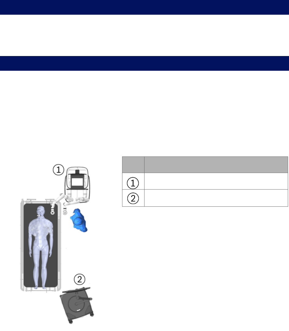
40 300-002547-00 rev7
Software Information
Select the About icon on the Tower Touchscreen, Cart Touchscreen, or laptop
logon menu to view information about the Monarch Software, including the UDI
and copyright.
Suggested Bronchoscopy Suite Configuration
The following is a suggested configuration of where to place the Cart and Tower
in respect to the patient’s left side in the bronchoscopy suite. You can also mirror
the same configuration for the patient’s right side if it would be more appropriate.
The length of the Monarch Bronchoscope cable that attaches to the Tower is 9ft.
The length of the Tower umbilical cable that attaches to the Cart is 20ft. These
cable lengths determine the maximum distance that the tower and cart can be
separated during any time that the system is powered on.
Item Description
Cart with robot arms facing the Tower.
Tower

300-002547-00 rev7 41
Prepare the Bronchoscopy Suite
1. Bring the following Monarch single-use items into the procedure room.
a. Bronchoscope Fluidics Tubing.
b. Working channel instruments (Aspirating Biopsy Needle, etc.).
c. Bronchoscope Patient Introducer Kit (includes Bronchoscope Patient
Introducer and Bronchoscope Swivel Adapter).
d. Monarch Bronchoscope System (includes Monarch Bronchoscope and
Monarch Bronchoscope Sheath).
e. Monarch Bronchoscope Sheath Valve.
f. Navigation Patient Patches.
2. Bring Tower into room and place in the desired location in the procedure
room.
3. Bring Cart into room and position it where it does not hinder normal room
setup.
4. Plug in the umbilical cable from the Tower to the Cart.
5. Plug in the Tower to a dedicated electrical power outlet.
6. Plug in the Cart to a separate, dedicated electrical power outlet.
Ensure access to the Tower and Cart a.c. mains inlet cables is unimpaired as
these are the mains disconnect devices.
7. Power the system on by pushing the power button on either the tower or the
cart.
8. Select the Lung icon on the Tower Touchscreen.
9. Log on to the Tower with your user name and password.
10. Load the desired patient case using the CD of the patient’s CT in order to
plan paths, or the Monarch USB drive with planned paths completed.
Prepare the Patient
1. Once the patient enters the room, place the patient close enough to the head
of the table, with the patient head no more than 230mm away from the top
edge of the table. It is recommended to use a headrest.
2. The anesthesiologist sedates the patient for intubation.
NOTE: Endotracheal tube should be placed no closer than 40mm from the main
carina to facilitate navigation initialization.
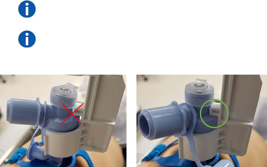
42 300-002547-00 rev7
3. Anesthesiologist or physician will intubate the patient. Once the endotracheal
tube is placed, the tube can be cut if desired.
Use of this device is restricted to endotracheal tubes 7.5mm and greater.
The patient should not be moved when the Monarch Bronchoscope
System or related equipment is inserted into patient airways.
4. Place the Bronchoscope Patient Introducer Mount on the bed rail near the
patient’s head on the side of the bed opposite that which the cart will be
positioned.
5. Open the Bronchoscope Patient Introducer Kit package.
6. Attach the Swivel Adapter to the endotracheal tube.
7. Place Bronchoscope Patient Introducer into the mount.
8. Connect the Patient Introducer to the Swivel Adapter and align the patient
introducer perpendicular to patient, parallel to the top of the bed with the
opening facing the side of the bed where the Cart is placed.
NOTE: Proper alignment and attachment of the Bronchoscope Patient
Introducer is important for smooth scope insertion and minimizing air leakage
during ventilation.
NOTE: Improper alignment may also cause navigation accuracy to be impaired.
a. Make sure the Swivel Adapter is fully seated, as shown in the following
image (right).
b. Make sure the Bronchoscope Patient Introducer is vertical, snapped in,
and the arm knob on the Bronchoscope Patient Introducer mount is
completely tightened.
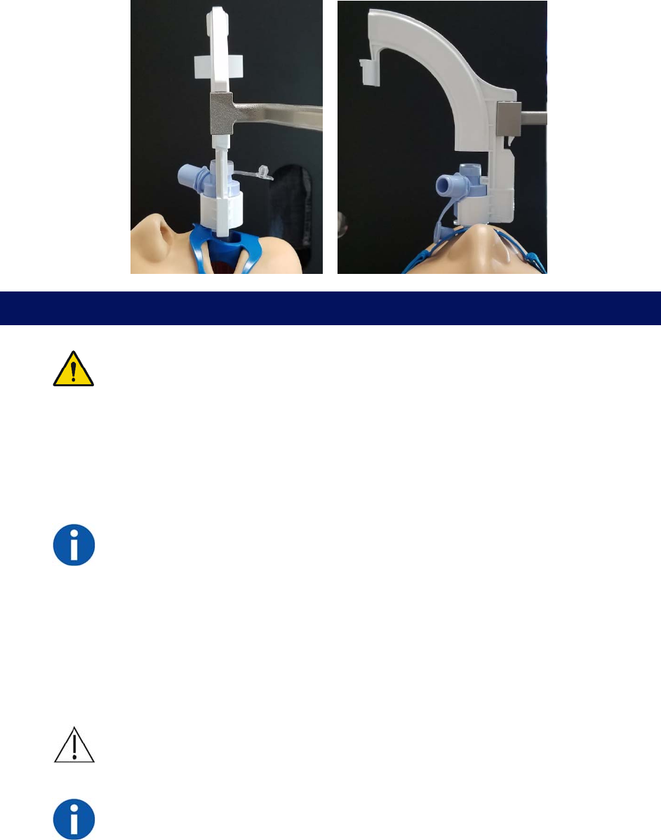
300-002547-00 rev7 43
Prepare the Monarch Bronchoscope System
WARNING: The bronchoscope and sheath must be lubricated prior to insertion.
Failure to lubricate the bronchoscope and sheath may cause buckling and poor
scope driving responsiveness.
1. Open the Monarch Bronchoscope System package and remove the pouched
tray.
Keep the package and all its components for repackaging, in case the
Bronchoscope System needs to be returned at the end of the procedure.
NOTE: If the bronchoscope and/or sheath is dropped after being removed from
its packaging, replace the bronchoscope and sheath to ensure that its
cleanliness has not been compromised.
2. Open the pouch on the device handle side and pull out the tray, ensuring that
the device handles do not fall out of their wells.
3. Hang the tray on a hook on the side of the Tower.
4. Remove the Monarch Bronchoscope from its packaging tube and lubricate
the shaft. Not lubricating may cause navigation accuracy to be impaired.
CAUTION: Placing lubricant on the camera may result in compromised image
quality.
NOTE: Use only silicone-based lubricants such as Silkospray Universal Silicone
Spray. Do not use water-based lubricants. Use of such lubricants will increase
friction between the bronchoscope and sheath while driving.
5. Insert the Monarch Bronchoscope back into the packaging tube and tray until
the procedure begins.
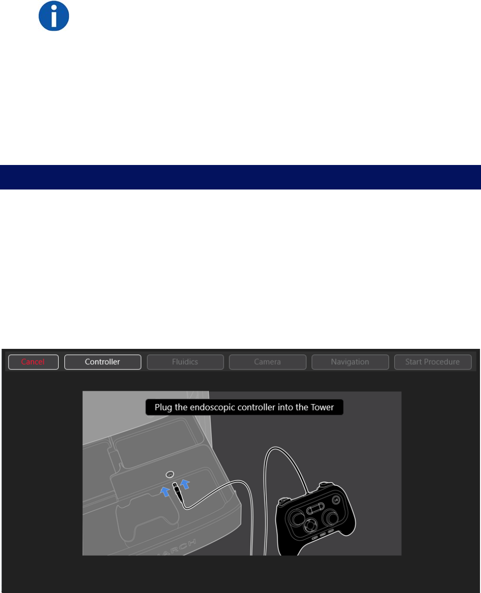
44 300-002547-00 rev7
6. Remove the Monarch Bronchoscope Sheath from its packaging tube and
lubricate the shaft.
NOTE: Use only silicone-based lubricants such as Silkospray Universal Silicone
Spray.
7. Open the Bronchoscope Sheath Valve package.
8. Place the Bronchoscope Sheath Valve over the Luer fitting on the back of the
Monarch Bronchoscope Sheath.
9. Insert the Monarch Bronchoscope Sheath back into the packaging tube and
tray until the Cart is set up and the procedure begins.
During start up, if the system is not yet initialized, a pop-up notification
appears to inform you to wait.
Monarch Tower System Setup Guidance
Use the Monarch Tower Software guidance prompts to confirm steps that you
have completed.
Monarch Controller
1. Plug in the Monarch Controller to the tower.
2. When Controller button turns green, press Fluidics to continue.
As each segment of the setup is complete, the corresponding button turns
green.
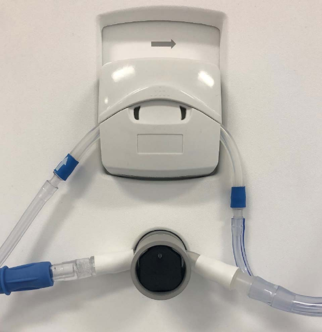
300-002547-00 rev7 45
Fluidics System
1. Unpack the Bronchoscope Fluidics Tubing from its sterile packaging. Connect
the end of the tubing with a Luer fitting valve to the Monarch Bronchoscope
System handle Luer fitting.
2. Attach the tubing (blue stripe) to the irrigation pump. Note the direction of the
arrow, which defines pumping direction.
3. Close the pump cover, and connect the tube to the saline bag with the
attached spike.
4. Open the clamp on the saline line. Hang saline bag on Tower hook.
5. Attach the other (clear) tubing to the aspiration pinch valve by sliding it in. To
slide the aspiration tubing into the aspiration pinch valve, you can open the
pinch valve by pushing in the front black surface of the aspiration pinch valve
or by engaging the vacuum button on the Controller.
6. Attach the connector to the operating room suction or vacuum (canister).
7. Use the Controller’s upper-left buttons to prime the irrigation line with fluid
and to close the pinch valve for the aspiration line.
8. Press Camera to continue.
46 300-002547-00 rev7
Camera
1. Plug in the Bronchoscope camera cable to the tower.
2. Verify that the camera is live.
3. Press Navigation to continue.
Navigation
1. Plug in Monarch Navigation Field Generator to the tower while leaving it in
tower cabinet.
2. When the button turns blue, press DONE.
3. Remove Monarch Navigation Patient Sensors from the storage pouch in the
door on the side of the tower.
4. Plug in Navigation Patient Sensors to the tower.
5. Attach Navigation Patient Sensors to the patient using the disposable
adhesive Navigation Patient Patches. Patches are designed for a single
adherence. Attach the labeled sensors as follows:
a. L patient left 8th rib mid axillary line.
b. R patient right 8th rib mid axillary line.
c. M patient sternal notch.
6. Remove the Monarch Navigation Field Generator Mount from storage
compartment on the side of the tower.
7. Attach the Field Generator Mount to the bed rail on the side of the patient that
the target nodule will be.
8. Remove the Navigation Field Generator from tower drawer.
9. Place the Field Generator into the mount by sliding into the top of it. Make
sure that the notch of the Field Generator slides into one of the holes in the
mount.
10. Position the Field Generator such that it is at the mid-chest wall
approximately 5 cm from the patient’s chest.
11. Swipe left on the Tower screen to move past the navigation setup
instructions.
12. Adjust the Field Generator to ensure that the Patient Navigation Sensors are
within the field of lung volume. On the tower screen, all three sensors will turn
green if the Field Generator is in the optimal position.
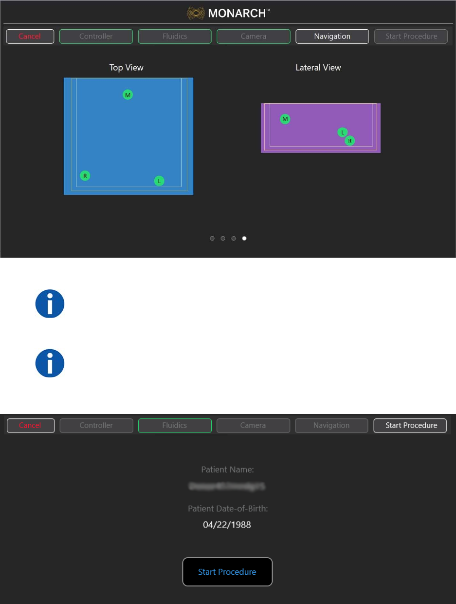
300-002547-00 rev7 47
13. Press Start Procedure to continue.
NOTE: Ensure fluoroscopy system has a minimum clearance distance of 70 cm
vertically and laterally from the Field Generator. To do so may affect the
measurement volume, contributing to inaccurate transformations.
NOTE: In larger patients, it may be difficult for all three sensors to turn green. In
this case, the sensor furthest away from the Field Generator should be the one
designated as yellow or orange. Yellow, orange, and red indicate that portions
of the lung may have sequentially less accurate navigational targeting.
48 300-002547-00 rev7
Monarch Cart System Setup Guidance
NOTE: Ensure there is appropriate clearance between the Monarch Cart and
the patient and staff.
Unstow Cart
1. Press Start to confirm that the Monarch Cart is ready to set up to the patient.
2. Roll the Cart to the correct side of the patient with approximately 36” between
the cart and the bed.
3. A blue box will highlight the direction that the arms will setup. Select which
side you want the robot arms to move to and press Unstow Arms to move
the robot arms in that direction.
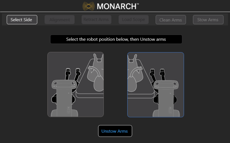
300-002547-00 rev7 49
4. Move the Cart to align the robot arms within approximately 2 inches of the
Patient Introducer.
5. Immobilize the Cart by pumping the foot pedal until the cart is lifted and the
green indicator light appears on the screen. You are unable to use the
software until the cart is immobilized.
Wait 5 seconds to ensure that the green indicator light appears before
continuing to the next step.
6. Press the button on the robot arm closest to the patient to adjust for fine
positioning of the robot arms to the Bronchoscope Patient Introducer.
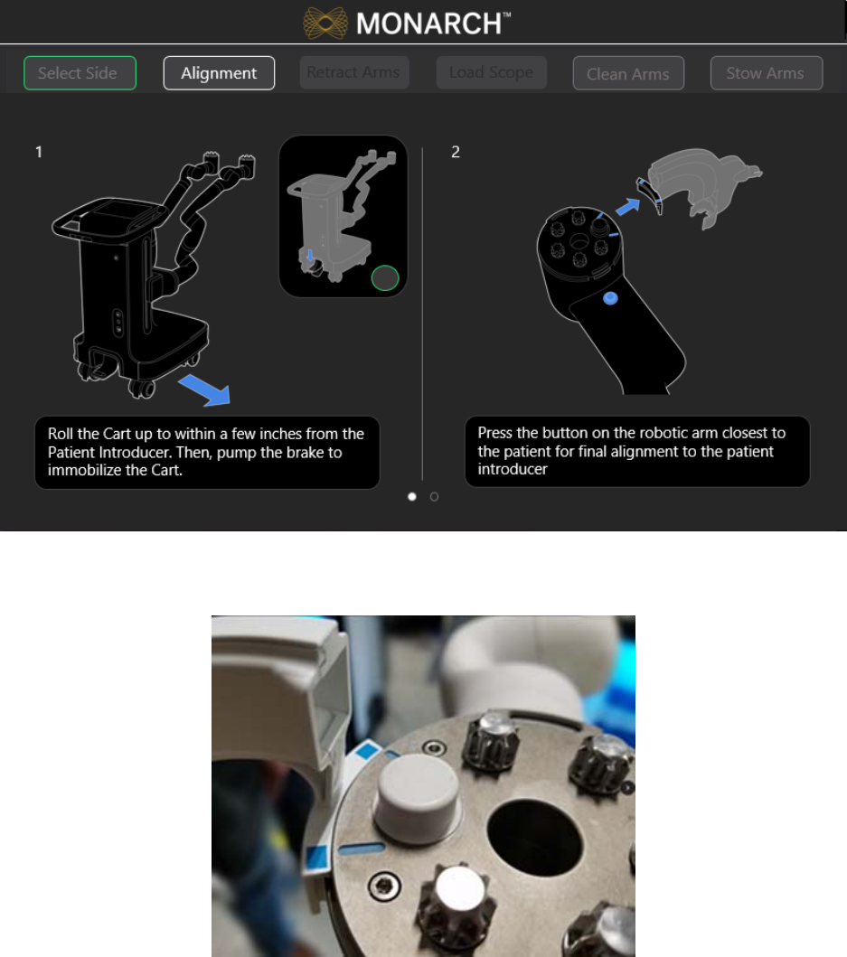
50 300-002547-00 rev7
7. Make sure the IDM touches the alignment feature (as shown in the following
image).
8. Press Set.
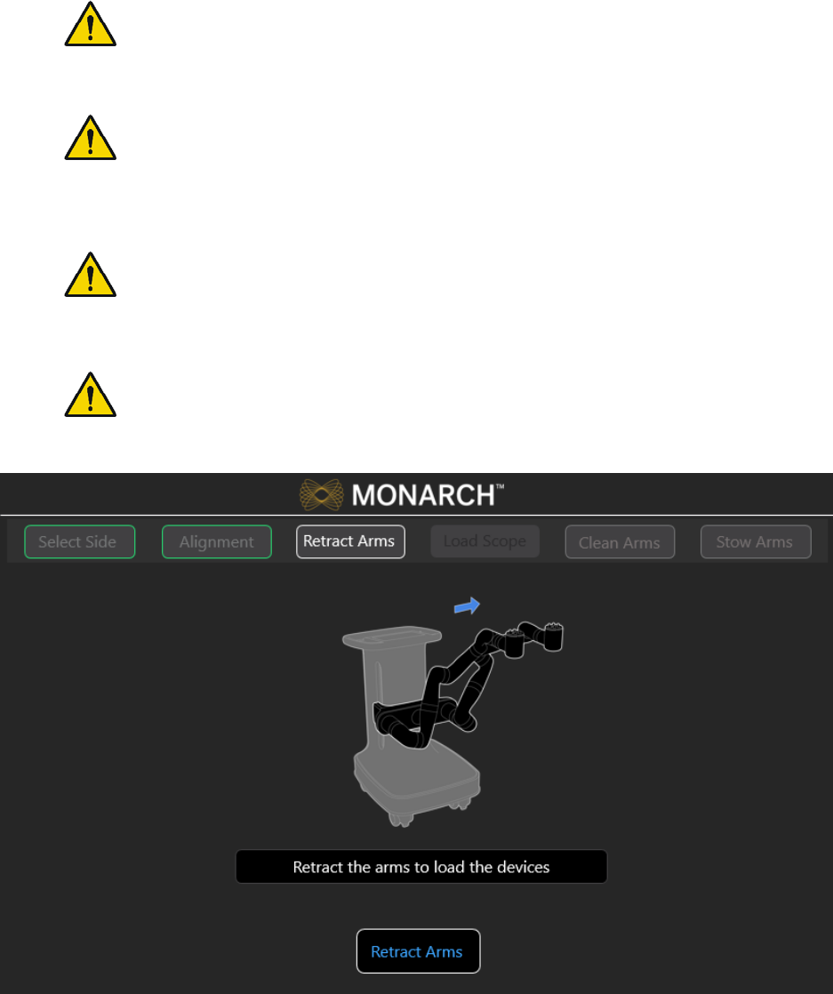
300-002547-00 rev7 51
Load the Monarch Bronchoscope System
WARNING: Do not reuse the Monarch Bronchoscope System, Bronchoscope
Fluidics Tubing, Bronchoscope Patient Introducer, or working channel
instruments. These devices are single-use only.
WARNING: Do not use the Monarch Bronchoscope System, Bronchoscope
Fluidics Tubing, Bronchoscope Patient Introducer, and working channel
instruments if sterile barrier has been damaged. Do not use if packaging is
opened or damaged.
WARNING: The bronchoscope and sheath must be lubricated prior to insertion.
Failure to lubricate the bronchoscope and sheath may cause poor scope
motion.
WARNING: Take care to manage cables and fluidics tubing. Both may present
a tripping hazard which can lead to user or patient injury or harm.
1. Press Retract Arms. Robot arms move to a loading position.
2. Remove the Monarch Bronchoscope System from the packaging tray.
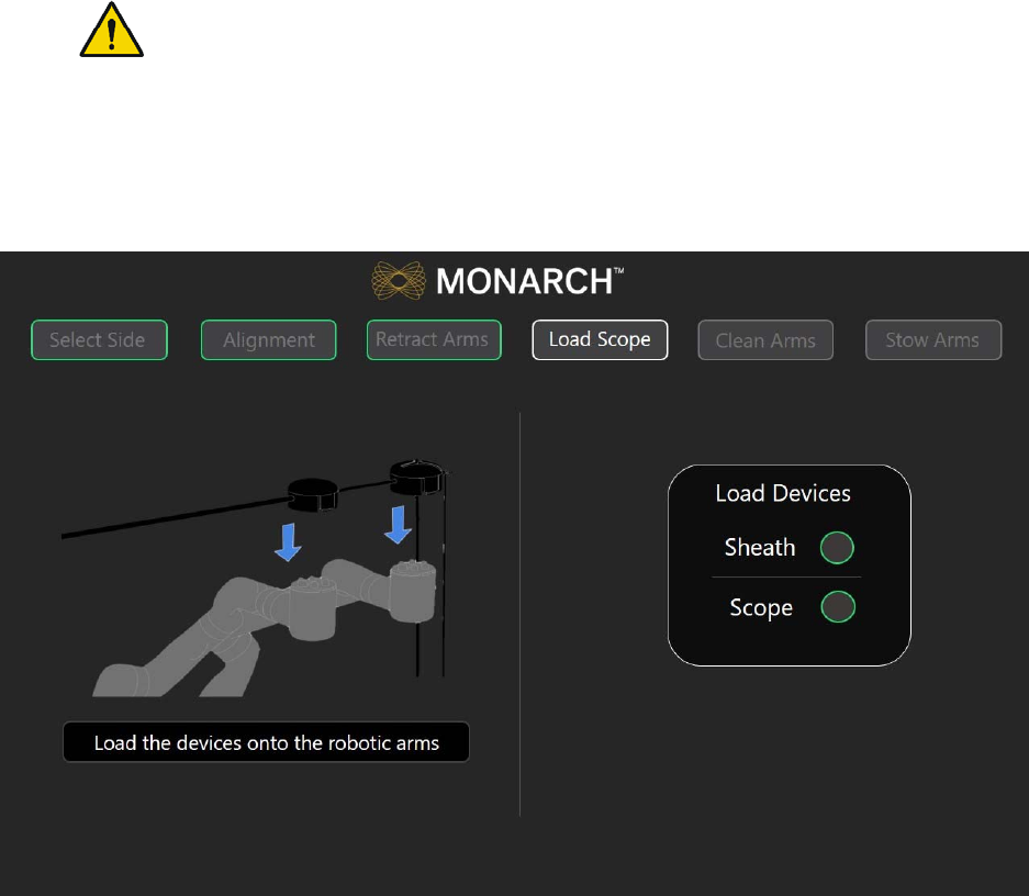
52 300-002547-00 rev7
3. Assemble the Monarch Bronchoscope and Monarch Bronchoscope Sheath
by inserting the bronchoscope through the Bronchoscope Sheath valve and
through the sheath.
4. Insert the tip of the Monarch Bronchoscope System into the Patient
Introducer up to the end of the bronchoscope swivel adapter.
5. Load the Monarch Bronchoscope System handles onto the robot arms. The
Monarch Bronchoscope Sheath should be loaded onto the robot arm closest
to the patient.
WARNING: Excessive load on the robotic arms may cause rotation, arm
slippage, or arm damage which may result in unintended motion and could
result in patient injury.
6. Ensure that the handles fully latch onto the robot arms by slightly pulling up
on the handles. Green indicator lights appear next to the Scope and Sheath
on the Load Scope screen when the Monarch Bronchoscope System is
detected by the system and is ready for use.

300-002547-00 rev7 53
Performing a Procedure
Overview ................................................................................................................... 54
Functional Descriptions of Monarch Components ..................................................... 54
Biopsy Instruments .................................................................................................... 57
Monarch Navigation Application User Interface ........................................................ 58
Procedural Steps or Actions ...................................................................................... 78
Perform Biopsy .......................................................................................................... 80
Post-procedure .......................................................................................................... 81
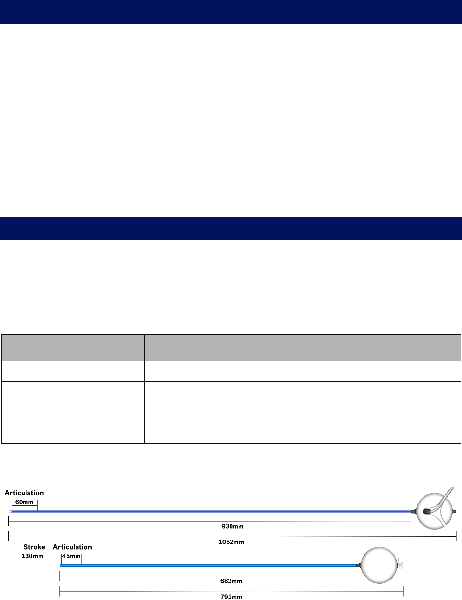
54 300-002547-00 rev7
Overview
Each procedure consists of tasks and each task has one or more steps. In
performing a procedure, you will typically perform the following steps:
1. Drive the Monarch Bronchoscope System forward to the main carina.
2. Initialize navigation.
3. Drive the Monarch Bronchoscope System to nodule.
4. Confirm nodule location.
5. Align the Monarch Bronchoscope System with nodule.
6. Insert the biopsy instrument.
7. Target and actuate the biopsy instrument.
Functional Descriptions of Monarch Components
Monarch Bronchoscope and Monarch Bronchoscope
Sheath
The Monarch Bronchoscope System works with two independently controlled
telescoping, articulating devices. The dimensions of each are as follows:
Monarch Bronchoscope Sheath Monarch Bronchoscope
Outer Diameter 6.0mm 4.4mm1
Lumen Diameter 4.7mm 2.1mm
Working Channel Length 791mm2 1052mm3
Articulation Section Length 45mm 60mm
1 Diameter measured at the Bronchoscope tip.
2 Takes into account use of the sheath valve.
3 Takes into account the bronchoscope valve.
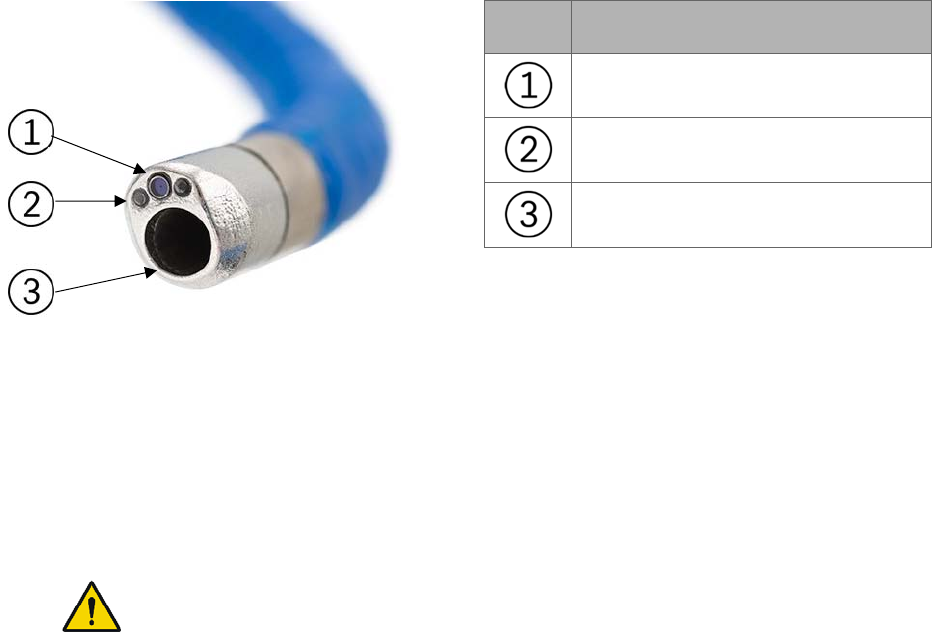
300-002547-00 rev7 55
Item Description
Camera
Lights (x2)
Working channel (2.1mm)
Monarch Platform Device Compatibility
Working channel instruments are restricted to those that are compatible with a
working channel diameter of 2.1mm.
Device Sterility
Contents supplied sterile using an ethylene oxide (EO) process.
WARNING: Contents supplied sterile using an ethylene oxide (EO) process. Do
not use if sterile barrier has been damaged. For single-use only. Do not reuse,
reprocess, or resterilize single-use products. Reuse, reprocessing, or
resterilization may compromise the structural integrity of the device and/or lead
to device failure which in turn may result in patient injury, illness, or death.
Reuse, reprocessing, or resterilization may also increase the risk of
contamination of the device and/or cause patient infection or cross-infection,
including but not limited to, the transmission of infectious disease(s) from one
patient to another. Contamination of the device may lead to injury, illness or
death of the patient. After use, dispose of product and packaging in accordance
with hospital, administrative and/or local government policy.
Monarch Controller
The Monarch Controller is used to control the Monarch Bronchoscope System.
The individual controls are described in the following table.
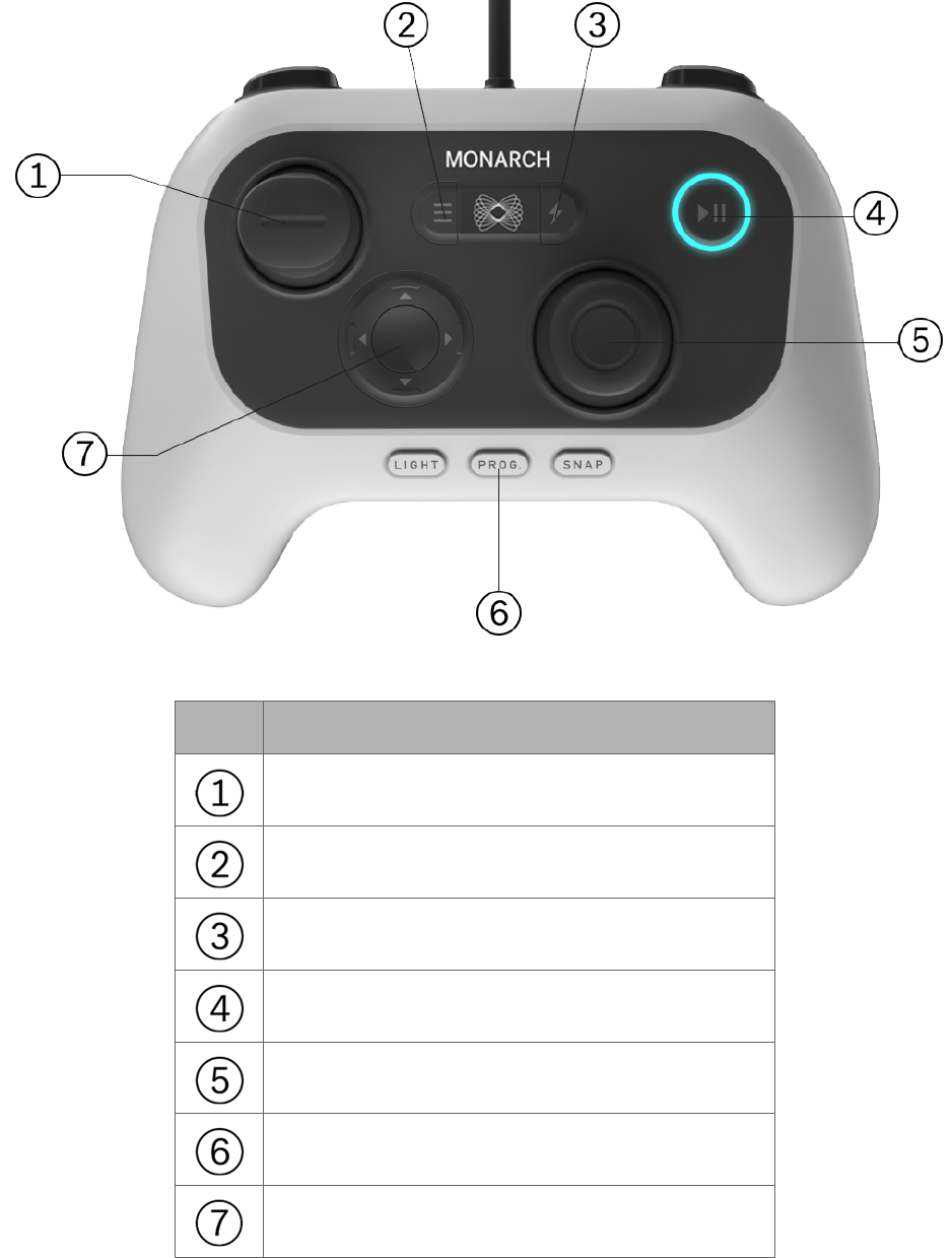
56 300-002547-00 rev7
Item Description
Insert/Retract joystick
Menu button
Quick Action button
Pause/Start button
Articulate (outer) and Relax (inner) joystick
Light, Program, and Snapshot buttons
Directional pad
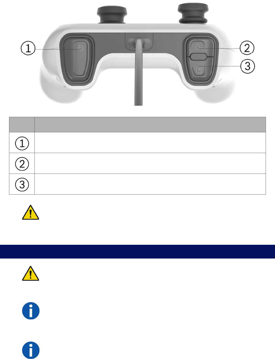
300-002547-00 rev7 57
Item Description
Toggle between Monarch Bronchoscope and Monarch Bronchoscope Sheath.
Irrigation button
Aspiration button
WARNING: Always secure the endoscopic controller. When in the enabled
state, dropping or other unintended joystick motion may lead to accidental
commanded motion which may cause patient injury, such as pneumothorax,
hemorrhage or endoluminal irritation.
Working Channel Instruments
WARNING: Working channel instruments are intended for manual operation
once the bronchoscope has reached the target location. Refer to individual
Instructions for Use included with each working channel instrument for
additional information.
NOTE: Presence of a fluoroscopy system near the Monarch Navigation Field
Generator may compromise navigation accuracy. When using the fluoroscopy
system, you should only refer to the live endoscopic views during manual
biopsy.
NOTE: Metallic working channel instruments near the scope tip may temporarily
compromise navigation accuracy. Examples include: instruments 20mm
proximal to the tip or activation of a radial ultrasound probe within the scope.

58 300-002547-00 rev7
Monarch Navigation Application User Interface
The Monarch Platform provides access to several custom views that combine the
live Monarch Bronchoscope, CT data, and virtual reconstructions of the airway
segmentation. These views can be mixed and matched based on physician
preference and rearranged during the procedure as needed.
• Primary Area (page 60)
• Scrolling Area (page 61)
• CT Area (page 62)
• Full Screen Mode (page 63)
• Live Bronchoscope (page 66)
• Virtual Bronchoscope (page 69)
• 3D Map View (page 70)
• Local View (page 71)
• Targeting Views (page 72)
• Axial, Sagittal, and Coronal CTs (page 74)
At the core of the Monarch Navigation Application is the Live Bronchoscope view
which provides vision in both the central airways and periphery. This camera
view is available from any part of the user interface.
The CT views include Axial, Sagittal and Coronal planes which reflect the
scope’s current position within the airway tree while also showing the location of
the target nodule. In addition to the traditional planar views, the user interface
includes several views with oblique slices based on the orientation of the scope.
These views include Local View.
Finally, the Monarch Navigation Application includes virtual views which are
computer-based reconstructions of the CT data. These views show the airways
and scope position from unique perspectives. The virtual views include Virtual
Bronchoscope, 3D Map, Local View, and Targeting Views.
The following images show a representation of the overall screen.
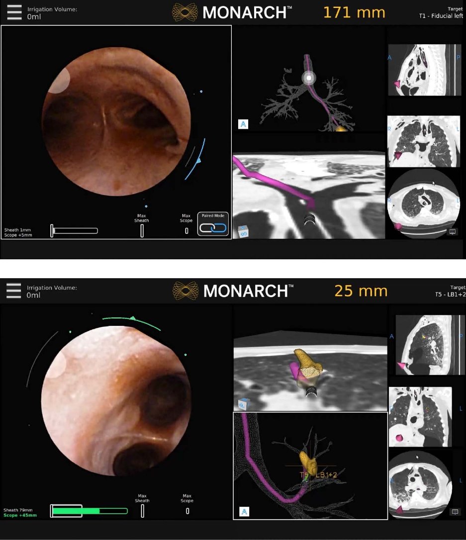
300-002547-00 rev7 59
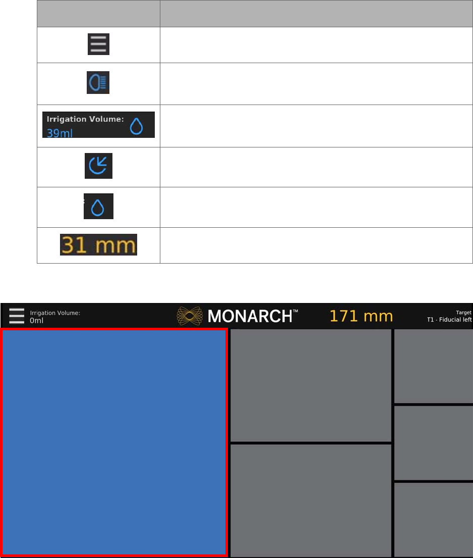
60 300-002547-00 rev7
Top Navigation Bar
Item Description
Menu icon
High Beam icon appears when the Light button is pressed.
The feature increases light emission from the tip.
Irrigation indicator: Estimated total volume delivered from the
pump is displayed. Text turns blue when irrigation is active.
Aspiration icon: Appears when aspiration is active.
Irrigation icon: Appears when irrigation is active.
This text reflects the distance to from the tip to the nodule.
Primary Area
Any of the views from the center column can be selected using either the
Touchscreen or the select button on the Monarch Controller to “promote” the
view to the larger window.
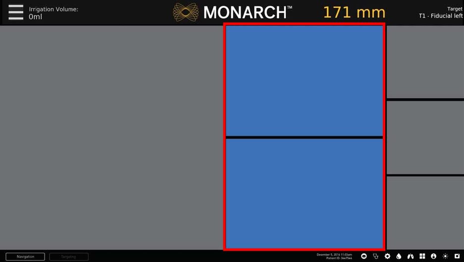
300-002547-00 rev7 61
This larger window is called the Primary Area. The increased size allows more
information to be shown, in the form of more detailed graphics. When the Live
Bronchoscope view is promoted to the Primary Area, additional data not
available in the smaller viewing window appears.
See Live Bronchoscope (page 66) for examples of how the Primary Area can
show additional information.
Scrolling Area
The center column of the Monarch Navigation Application can be scrolled to
present any two relevant views. This column can be scrolled, using the up,
down
,
and select navigation buttons on the Monarch Controller
.
The Scrolling Area contains four views discussed in the following:
• CT Area (page 62).
• Full Screen Mode (page 63).
• Menu System (page 63).
• Navigation Views (page 65).
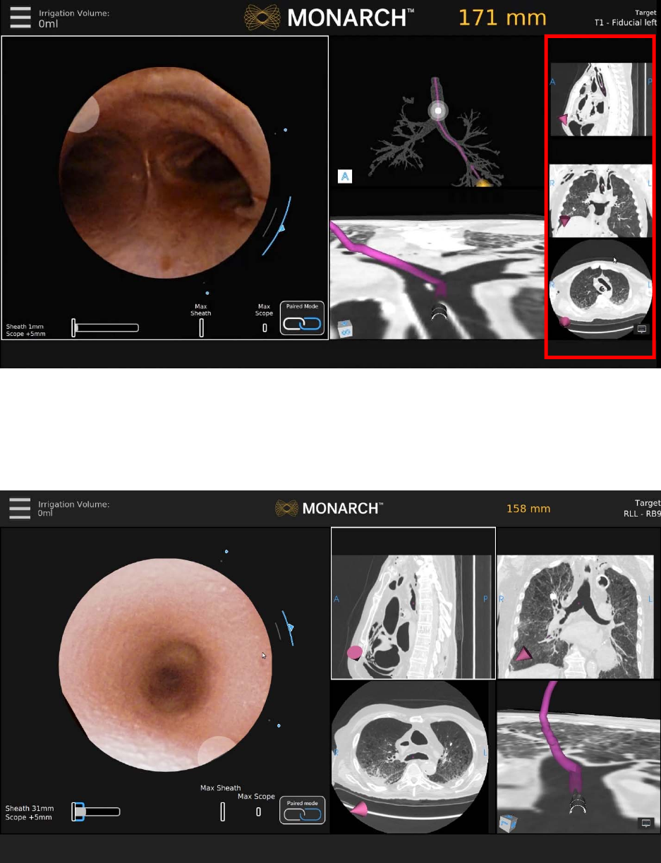
62 300-002547-00 rev7
CT Area
The right column offers a collection of supplementary CT views. The CT Area
does not scroll and views cannot be promoted from the CT Area to Primary Area.
Instead, the views can be selected for zoom to show more detail. When
selected, an alternative view window configuration appears with enlarged CT
slices as shown below.
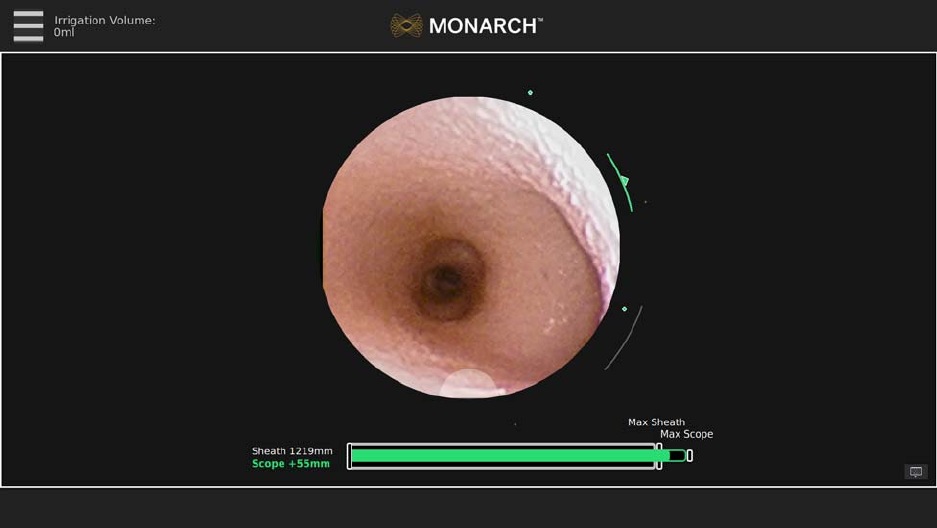
300-002547-00 rev7 63
This view was designed to support physicians who use the Axial, Sagittal, and
Coronal CT views during the procedure. Selecting a CT window automatically
dismisses the view.
Full Screen Mode
Live Bronchoscope – Full Screen Mode
When the Live Bronchoscope view is the Primary Area, selecting the Primary
Area enlarges it to a Full Screen Mode. This removes the Monarch Navigation
Application and displays only the Live Bronchoscope image. This is also the view
that appears if you perform a case without a navigation plan.
Selecting the Full Screen Mode image automatically returns it to Primary Area.
Menu System
The menu system is available from the menu button on the Monarch Controller
as well as the upper-left of the user interface and includes functions that you can
access during the procedure such as selecting a new target or loading a new
plan. The menu system is also used to control robot settings or exit the system.
Patient name and medical record number can be displayed on the main menu for
quick reference. Hiding it within the menu makes it easily accessible but does not
expose the information for screenshots and video.
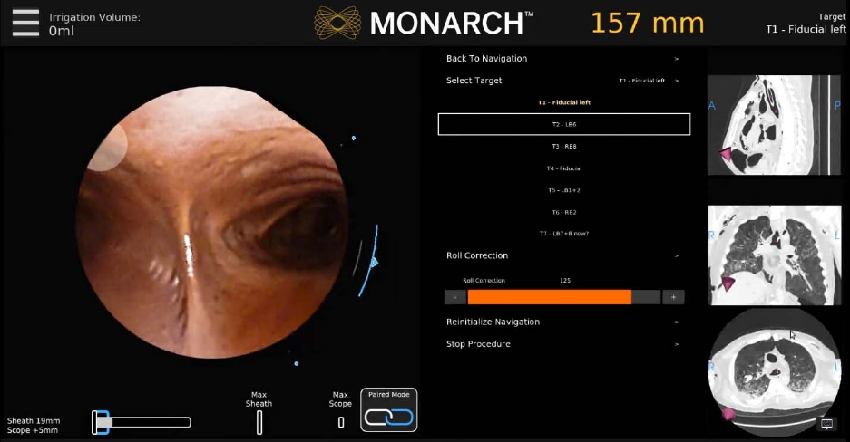
64 300-002547-00 rev7
Select the menu item using the Monarch Controller or press the corresponding
item on the screen.
Back to Navigation
Press Back to Navigation to return to the Navigation tab.
Select Target
Press Select Target to select a target to navigate to.
Camera Parameters
Press Camera Parameters to adjust the camera roll.
Reinitialize Navigation
Press Reinitialize Navigation to reset the navigation procedure from the main
carina.
Stop Procedure
Press Stop Procedure and choose one of the following:
Export Media to USB.
The Monarch USB drive must be inserted for this feature to be available.
Return to System Set-up.
Load New Patient Case.
Logout.
Shutdown.
300-002547-00 rev7 65
Navigation Views
The Monarch Navigation Application integrates a pre-procedure-computed
tomography scan into a peri-procedure interface displaying endoscope tip
location relative to the pre-procedure scan anatomy. The navigational information
displays the Monarch Bronchoscope tip location relative to the CT scan. The
application’s interface includes a virtual representation of the lung with scope tip
location. The following views describe the way that the scope tip location appears
on the CT scan images or virtual representations.
• Live Bronchoscope (page 66).
• Virtual Bronchoscope (page 69).
• 3D Map View (page 70).
• Local View (page 71).
• Targeting Views (page 72).
• Axial, Sagittal, and Coronal CTs (page 74).
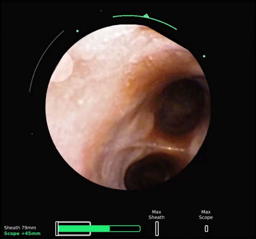
66 300-002547-00 rev7
Live Bronchoscope
The Primary Area of the Live Bronchoscope shows more detailed information than when located
in the Scrolling Area.
The core of the Monarch Navigation Application is the Live Bronchoscope view
which provides vision in both the central airways and the periphery. This camera
view is always displayed in either Full Screen Mode, Primary Area, or Scrolling
Area positions.
The Primary Area of Live Bronchoscope presents the camera image cropped to a
660px circle. Two concentric arcs represent the articulation of the scope (inner)
and sheath (outer). As articulation increases, the arcs increase in length. The
dots indicate the max articulation of the sheath/scope. The dots turn to hash
marks when max articulation is reached. The device that is actively being
articulated will be colored (blue: sheath; green: scope).
The location of the working channel is represented by a half circle at the edge of
the camera image.
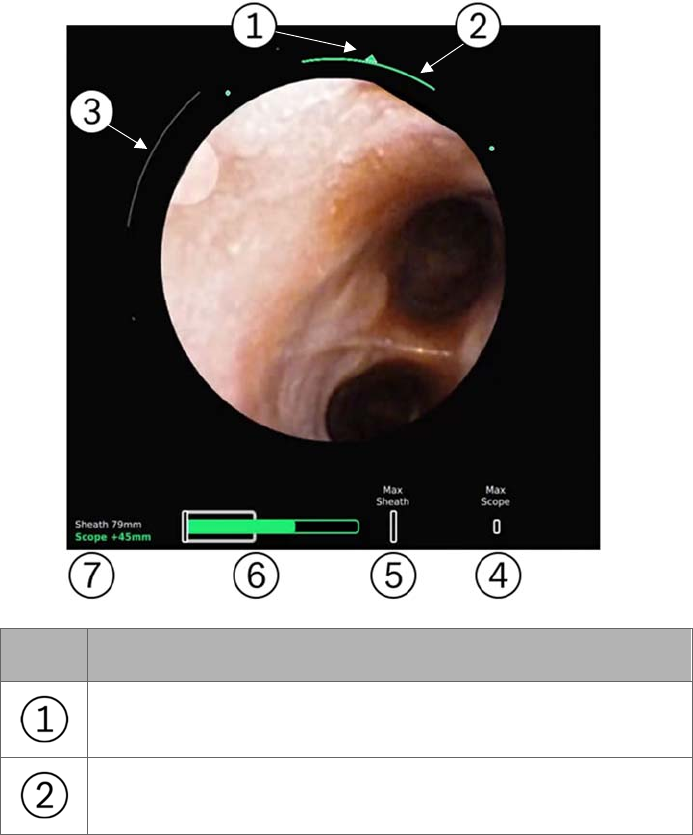
300-002547-00 rev7 67
Insertion depth is at the bottom of the screen. The
gray bar (which turns blue when
the Sheath is selected)
indicates the sheath insertion. The green bar indicates the
insertion of the scope relative to the sheath. The green outline indicates the
remaining stroke length of the scope. The hash marks indicate max insertion of
the sheath and scope respectively. The numeric measurements are the relative
insertion of the sheath (from the point of navigation initialization) or the scope
(relative insertion from sheath). The selected device (scope or sheath) is in bold
and is colored. When both the scope and sheath are active together, the “Paired”
icon appears, indicating that the device tips are flush and insertion/articulation
will insert/articulate both scope and sheath together.
The design of the Live Bronchoscope view changes when positioned in the
Scrolling Area compared to the Primary Area. Scope and sheath insertions are
reduced to numbers are in this view in order to reduce visual clutter.
The Full Screen Mode adopts the Primary Area design.
Item Description
Direction of articulation
Magnitude of Bronchoscope articulation

68 300-002547-00 rev7
Item Description
Magnitude of Sheath articulation
Maximum insertion that the Bronchoscope can reach
Maximum insertion that the Sheath can reach
Represents the relative insertion of the Bronchoscope
(green) into the Sheath (white)
Relative insertion values for the Bronchoscope and Sheath
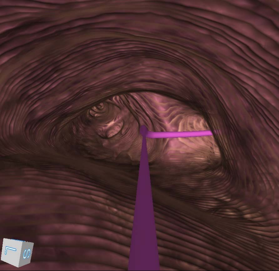
300-002547-00 rev7 69
Virtual Bronchoscope
The Virtual Bronchoscope view shows the scope position and orientation from
inside the airways, generally mirroring the view of the live camera. The Virtual
Bronchoscope view is designed to help visualize the next turn. It is a real-time
virtual representation of the pathway that updates relatively with camera pitch,
yaw, roll, and position along the planned path.
The Virtual Bronchoscope shows the pathway as a 3D line in the center of the
path that reflects the color of the available paths. Whenever the scope is
traveling on two or more paths, the two paths appear overlaid.
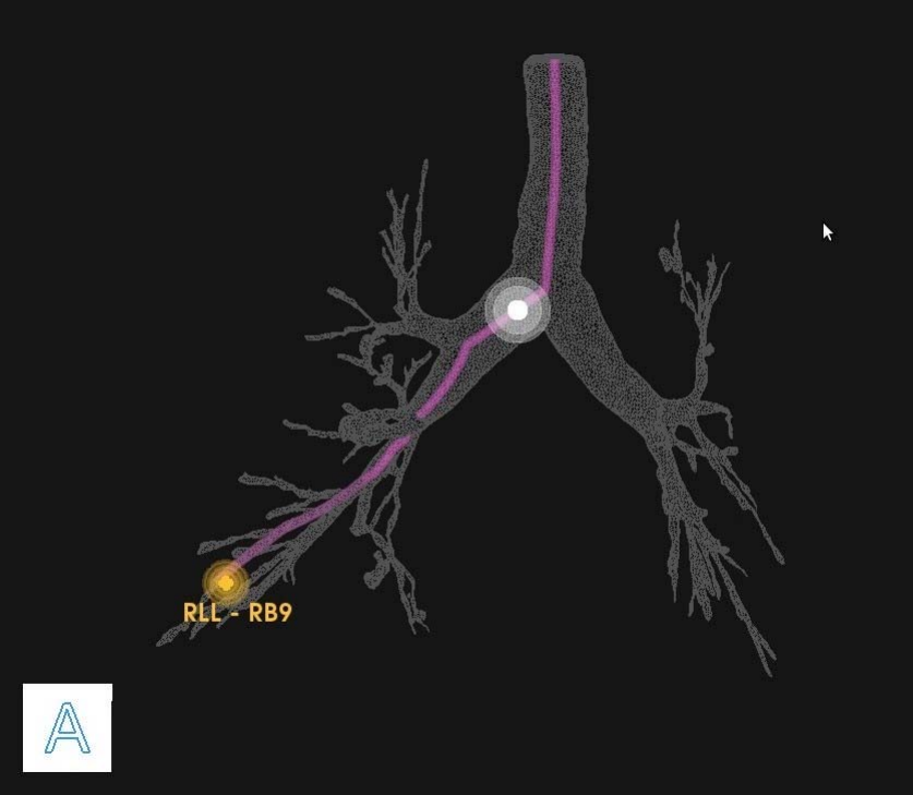
70 300-002547-00 rev7
3D Map View
Example of a planned pathway relative to the airway tree: The white ball
represents the scope position and the yellow ball represents the target.
3D Map view is a virtual representation of the patient’s airway tree with the
location of the planned pathways and targets superimposed. As the scope moves
through the airways, its position is reflected on this map. Orientation is
represented by a cube representing the direction of anterior/posterior/inferior/
superior/left/right which rotates in three dimensions in response to scope
movement.
By default, this view is displayed in the scrolling column upon starting navigation.
The zoom and rotation of the airway tree can be performed on the Touchscreen
on the tower as well as on the Monarch Controller.
When you leave the segmented path of the airways, the Monarch Navigation
Application continues to trace the path that you have taken in the 3D Map. The
scope trail is represented in yellow as the following image shows.
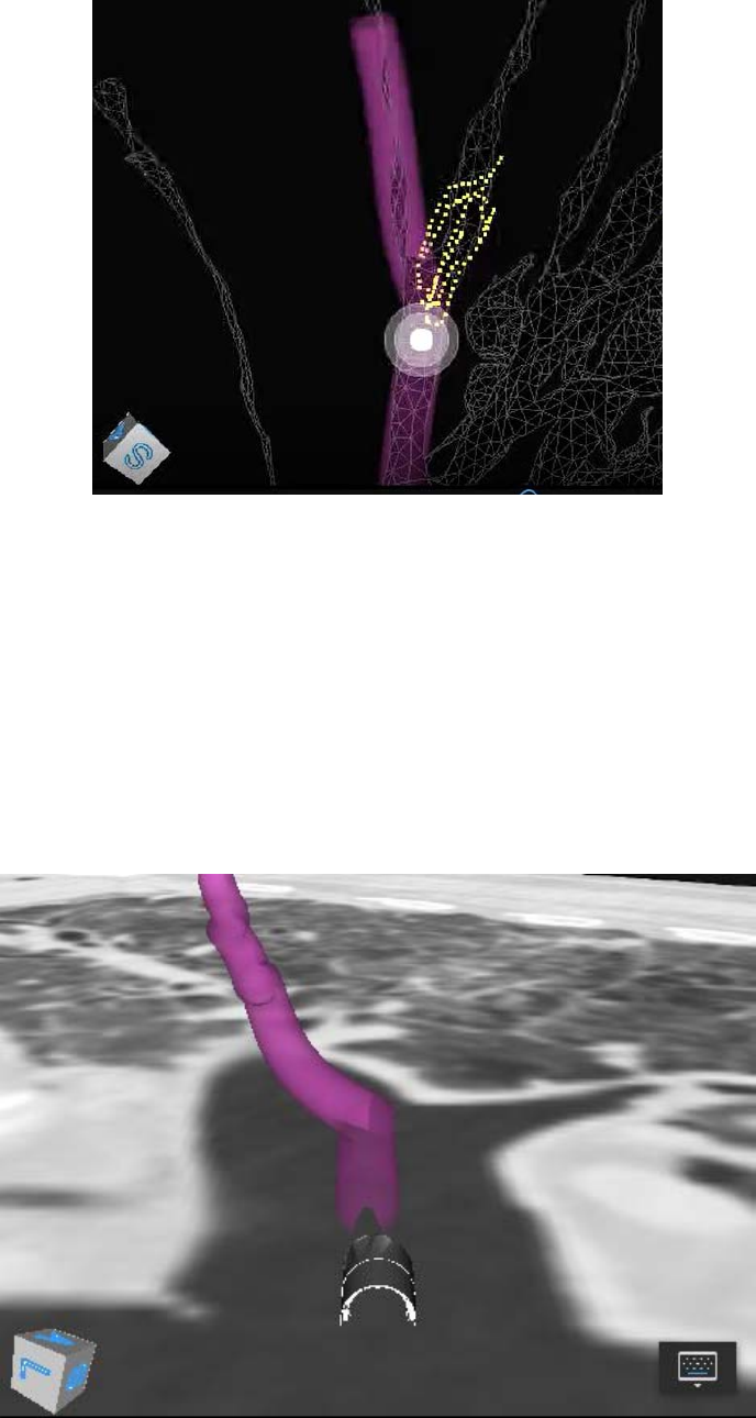
300-002547-00 rev7 71
Local View
This CT-based view combines a virtual representation of the nodule with an
oblique slice of the CT volume based on the scope orientation.
For targeting, the CT plane intersects the virtual nodule, allowing you to
determine when the target is in plane. The CT forms a virtual “water line,”
showing the point of intersection. The nodule should still be slightly visible when
underneath the plane of the CT. The pathway is represented in this view as a 3D
line that travels in and out of the CT plane-based path and airway direction.
A 3D representation of the scope tip appears in plane at the start of the pathway.
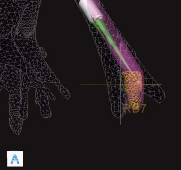
72 300-002547-00 rev7
Targeting Views
Orbit View
The Orbit view for targeting shows the biopsy position from the nodule’s
perspective. The view “orbits” around the target allowing you to view the
alignment from different angles.
This view always focuses on the nodule and attempts to adaptively keep the
scope tip in frame during the approach by revolving around the nodule to keep
both it and the scope in view.
You can control the orbit by holding the quick action button or by the Monarch
Tower Touchscreen. Releasing the button maintains the new position.
The indicator at the tip of the scope turns green when it intersects with the nodule
to confirm alignment.

300-002547-00 rev7 73
Tip View
The Tip view is a targeting view that displays the biopsy position from the tip of
the scope’s perspective to aid in working channel alignment. The view is
comprised of a crosshair, which is aligned with the scope’s working channel, and
the nodule, which consists of a yellow grid. All other segmentation information is
removed.
To access the Tip view, select the Orbit view and tap the quick action button.
See Quick Action Button on page 77 for more information.
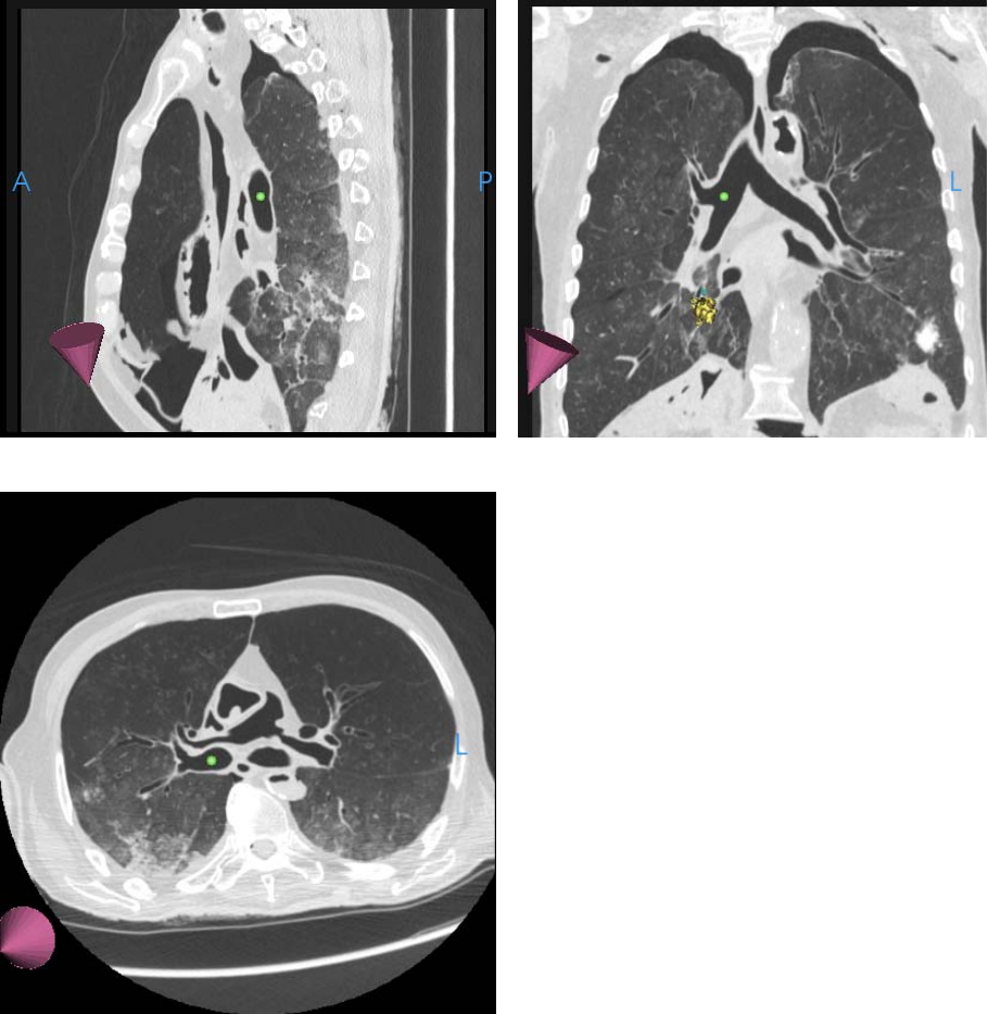
74 300-002547-00 rev7
Axial, Sagittal, and Coronal CTs
The planar CT views are sized to fit the sidebar windows and zoom window. The
Monarch Navigation Application adaptively scrolls and pans the CT based on
scope location, keeping the scope always in frame.
The CT images are sized to fit the width of the window, scrolling only vertically.
When zoomed using the quick action button, the CT images scroll horizontally.
In the following images, the axial, sagittal, and coronal slices of the CT scan at
the location of the scope tip appear. In these images, the scope tip is
represented by a green ball and the direction of the tip is represented by a purple
cone.
Sagittal
Coronal
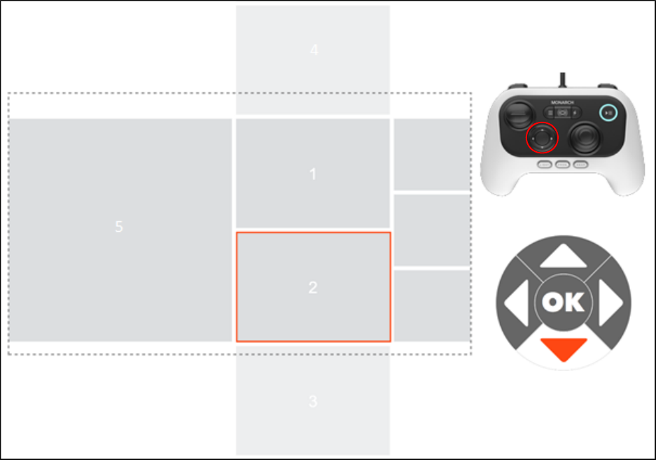
300-002547-00 rev7 75
Axial
Configuring View Screens
The Navigation views can be re-arranged during the procedure as needed. Using
the directional pad on the Monarch Controller, scroll through the Scrolling Area to
select your views. The following image is an overview of the view arrangement
structure.
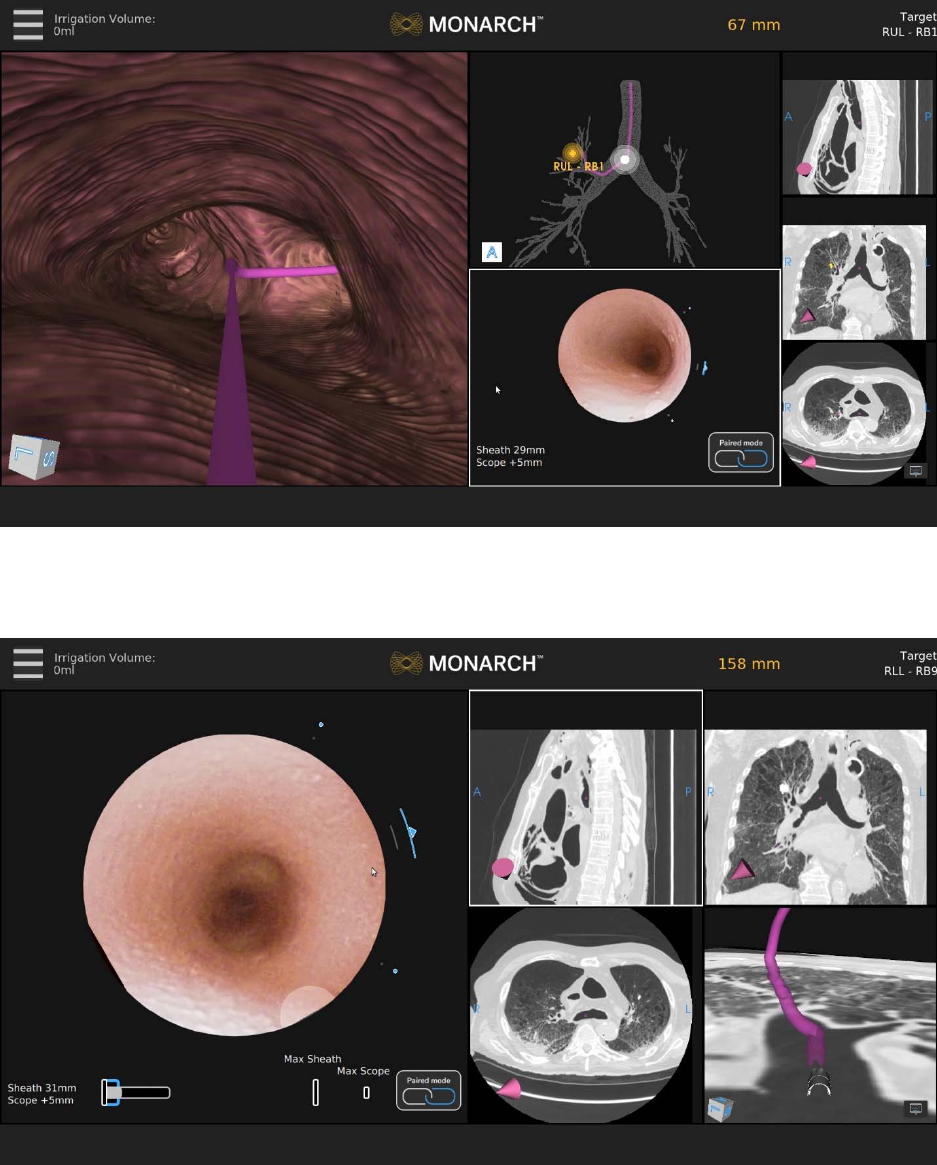
76 300-002547-00 rev7
Use the Scrolling Area to select among different views. Once you select a view,
it’s promoted to Primary Area.
If you select one of the CT views, the screen transitions to a CT-centric view as
described above.
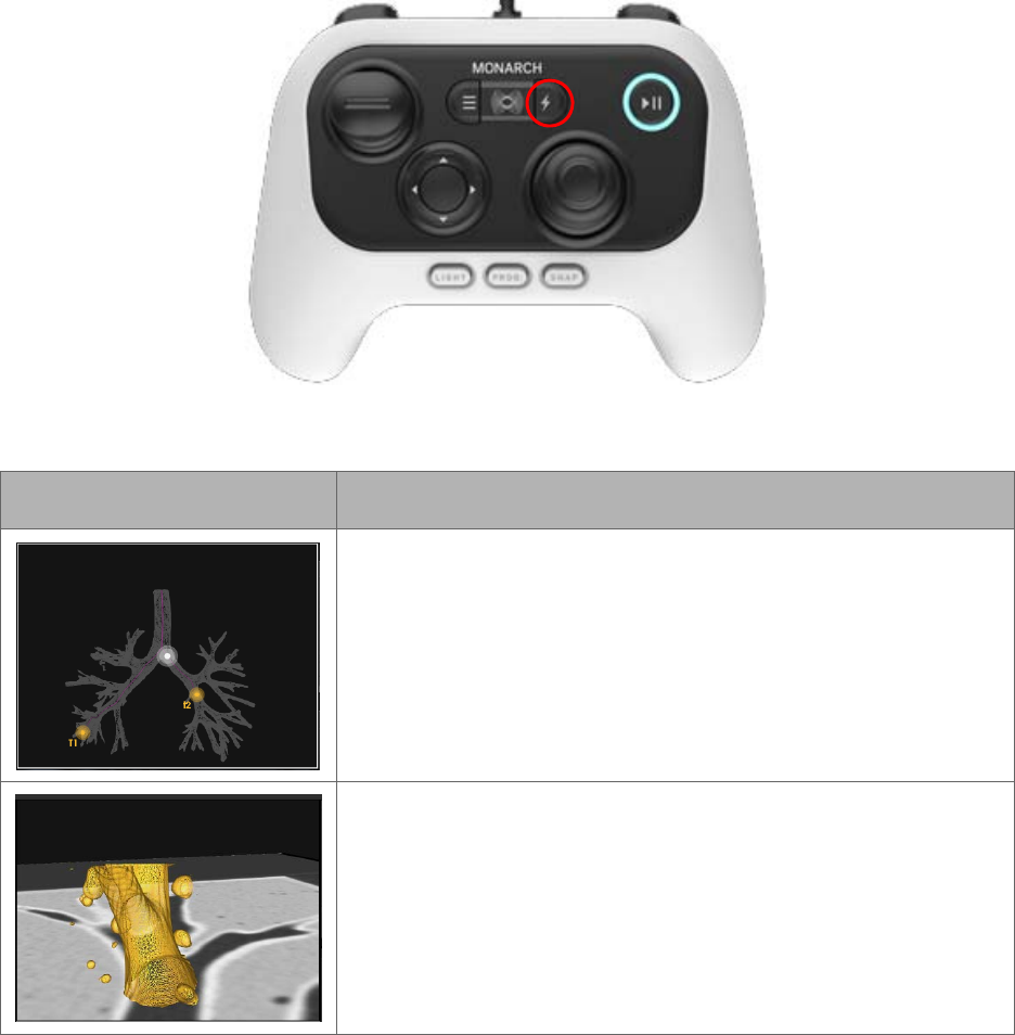
300-002547-00 rev7 77
Quick Action Button
If you have the Monarch Controller highlighting any of these screens, the quick
action button will give you the functions as illustrated below.
The Quick Action button activates on demand features that are unique for each view.
Item Description
3D Map View
Press: Zooms.
Hold: Rotates the image.
Local View
Press: Zooms. Decreases camera-to-target distance.
Hold: Orients virtual camera towards target.
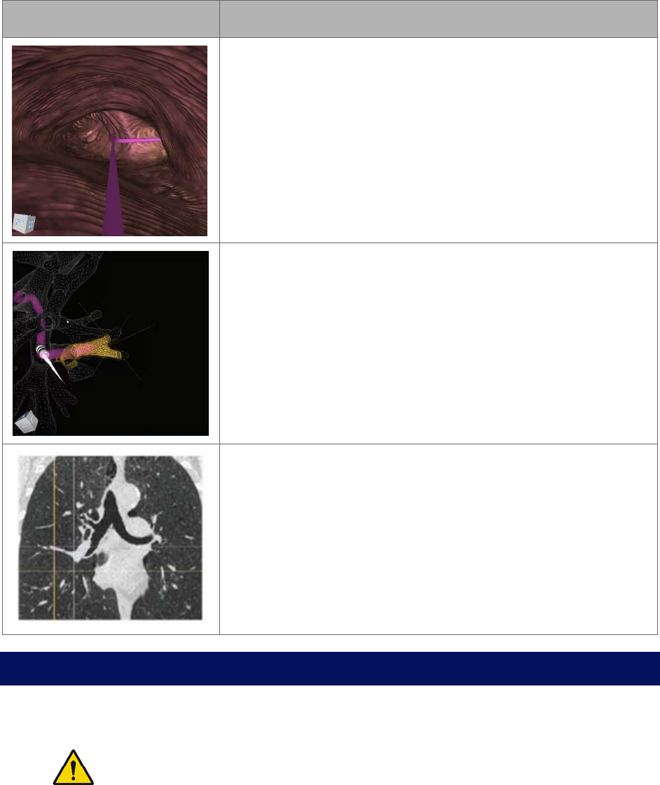
78 300-002547-00 rev7
Item Description
Virtual Bronchoscope View
Press: Elevates virtual camera.
Hold: Moves the camera along the paths in the order of
rank.
Orbit View
Press: Transitions from Orbit View to Tip View.
Hold: Rotates the view around the nodule.
CT Views
Press: Zooms.
Hold: Scrolls the slices from scope tip to target.
Procedural Steps or Actions
Scope Insertion
WARNING: Do not insert the bronchoscope unless there is a clear endoscopic
field of view. Failure to maintain visibility during insertion may result in patient
injury such as tissue damage, pneumothorax, or other adverse events.
1. On the Monarch Tower, press Start Procedure. The Monarch logo appears.
2. To activate the Monarch Bronchoscope System, take the Monarch Controller
and press the Pause/Start button on the controller.

300-002547-00 rev7 79
3. Press the Insert/Retract joystick to activate control of the Monarch
Bronchoscope System.
4. Insert the Monarch Bronchoscope System through the bronchial adapter and
endotracheal tube until you can visualize the main carina. You may need to
articulate the scope with the controller to avoid impact with the endotracheal
tube upon insertion.
Navigation Initialization
The Monarch Navigation Application continuously registers the scope tip location
to the pre-procedural CT scan. However, the Monarch Navigation Application
does require a little bit of information to initialize its starting location. The steps
are as follows:
1. Access the Adjust Camera Settings from the menu to rotate the camera
until the left and right airways are horizontal and press the Program button on
the Monarch Controller.
If the camera orientation is not adjusted so that the anterior direction
correlates to the top of the camera view, the camera orientation may not
match the Virtual Bronchoscope view during navigation.
2. Touch the main carina and press the Program button on the Monarch
Controller.
3. Retract the scope back some distance greater than or equal to 40mm and
press the Program button on the Monarch Controller.
NOTE: If you pull the scope too far out of the trachea and into the endotracheal
tube, an error message may appear and navigation initialization will need to be
repeated.
4. Perform contra-lateral registration by inserting the Bronchoscope System into
the opposite airway of the selected target until instructed by the interface to
retract a defined distance.
Make sure to keep the scope center-luminal as much as possible.
5. Retract until the navigation screens become visible. The system is ready to
begin the procedure.
Monarch Bronchoscope Advancement
Your right trigger finger is going to switch from the Monarch Bronchoscope
Sheath to the Monarch Bronchoscope. As you insert the Monarch Bronchoscope,
steer it in the direction that you want to go. The visual indicators update from the
Monarch Bronchoscope Sheath to the Monarch Bronchoscope, but you still can
see the articulation left on the Monarch Bronchoscope Sheath. The relative
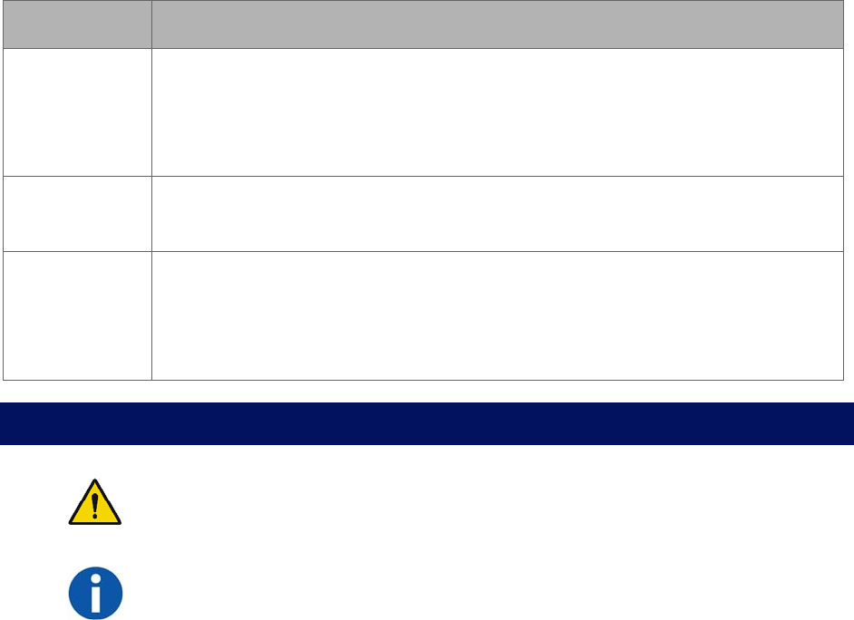
80 300-002547-00 rev7
insertion bar here indicates how much you have advanced beyond the Monarch
Bronchoscope Sheath.
Drive Modes
Drive Mode Description
Paired
When the scope/sheath tips are flush and the Paired icon appears, both
devices will insert and retract together. Articulation will command the sheath
articulation. Scope articulation will follow the sheath. In paired position, the
scope is extended 5mm out of the sheath.
Autorelax If the scope or sheath is retracted for >25mm without any additional
articulation commanded, the device will automatically relax.
Autopair If the sheath is advanced up to the scope, it will automatically pair with the
scope. If the scope is retracted into the sheath, the scope will automatically
pair with the sheath. Pairing has a momentary delay (1.5 seconds) to
prevent inadvertent pairing.
Perform Biopsy
WARNING: Ensure fluoroscopy system is operating properly and does not
interfere with the Monarch Platform before patient use.
NOTE: Do not irrigate with working instruments in the working channel. This can
cause pressure build up in the irrigation tubing.
Monarch Controller
You do not have to hold the Monarch Controller while taking biopsies. If you
decide to place the Monarch Controller down, press the pause button. This will
prevent any accidental manipulation. The Monarch Controller is also equipped
with an accelerometer if it is accidentally dropped or knocked off the table. This
automatically disables it. Pause the Monarch Controller and place it aside before
continuing with the biopsy.
Lavage
If you want to perform a lavage, you must disconnect the valve on the backend of
the Monarch Bronchoscope and access the working channel with a syringe.

300-002547-00 rev7 81
Administer Saline or Another Agent Through the Working
Channel
If you want to administer cold saline or any other agent through the working
channel with a syringe, you must disconnect the valve on the backend of the
Monarch Bronchoscope and access the working channel with a syringe.
Post-procedure
When the procedure is complete, use the following guidelines when you retract
the Monarch Bronchoscope System.
Retraction
CAUTION: Failure to relax the bronchoscope and sheath prior to retraction may cause
increased stress on the scope.
When retracting the Monarch Bronchoscope, fully relax the scope as you retract.
The Monarch Bronchoscope System will automatically relax the scope if you hold
the Retract joystick down for >25mm or if the Monarch Bronchoscope retracts
into the Monarch Bronchoscope Sheath.
As you retract the Monarch Bronchoscope into the Monarch Bronchoscope
Sheath, the Monarch Bronchoscope will automatically pair with the Monarch
Bronchoscope Sheath and Monarch Bronchoscope System retracts.
82 300-002547-00 rev7

300-002547-00 rev7 83
Cleaning, Maintenance, and Storage
Service and maintenance other than what is indicated in this chapter shall be performed
by trained Auris Service Personnel only.
Prepare the Patient for Discharge ............................................................................. 84
Remove and Clean Equipment ................................................................................. 84
Servicing .................................................................................................................... 87
CAUTION: Clean and disinfect the Monarch Platform by wiping components with a moist
disinfecting cloth. The bedside components should be cleaned and disinfected before each
case. All other components should be cleaned and disinfected at least monthly. The
Monarch Platform components are compatible with the following cleaning agents: distilled
water, 70% isopropyl alcohol solution, 96% ethanol, Super Sani-Cloth Germicidal Wipes -
Isopropyl Alcohol 55%, Clorox Healthcare Hydrogen Peroxide Cleaner Disinfectant -
Hydrogen Peroxide 1.4%, and Sani-Cloth Bleach Germicidal Wipe - Sodium Hypochlorite
0.63%.
Do not shut down the system while the Monarch Bronchoscope System is still inserted
in the patient.
Do not remove or disconnect system components (other than the Monarch
Bronchoscope System) while the Monarch Bronchoscope System is in the patient.
Do not remove protective covers from any system component. No user serviceable
parts are inside. Contact Auris Customer Care for any service concerns or questions.
Unpowered storage of the Monarch Platform for extended periods (longer than three
months) will result in degradation of the UPS batteries.
When disposing of instruments, accessories, or any of their components, follow all
applicable national and local laws and guidelines.

84 300-002547-00 rev7
Prepare the Patient for Discharge
Remove the Monarch Bronchoscope System
1. Detach the Bronchoscope System handles from the robot arms and remove
the Monarch Bronchoscope System from the patient.
2. Place it aside or immediately pre-clean and place back in the packaging.
Remove Monarch Navigation Patient Sensors
1. Detach Monarch Navigation Patient Sensors from the patient.
2. Place the Monarch Navigation Patient Sensors on the tower.
Remove the Bronchoscope Patient Introducer
1. Disconnect and discard the Bronchoscope Patient Introducer from the
Bronchoscope Swivel Adapter.
2. Remove the Bronchoscope Swivel Adapter and endotracheal tube from the
patient.
Remove and Clean Equipment
Disassemble and Clean the Monarch Bronchoscope
System
If necessary (e.g. product complaint investigation), the Monarch Bronchoscope
System may be returned to Auris per the following instructions. Otherwise, all
single-use devices, including the Bronchoscope and Bronchoscopic Sheath,
should be disposed of according to applicable national and local laws and
guidelines.
NOTE: Follow hospital, local, and state policies and guidelines for handling
used medical devices.
Pre-cleaning the Monarch Bronchoscope System
1. Wipe down external shafts of the Monarch Bronchoscope and Monarch
Bronchoscope Sheath with pre-cleaning solution.
NOTE: Recommended pre-cleaning solution is First Step by Cygnus (500 mL).
Follow the manufacturer's instructions for specific pre-cleaning solution usage.
300-002547-00 rev7 85
2. Immerse distal tip of the Monarch Bronchoscope into the pre-cleaning
solution and aspirate enough pre-cleaning solution to remove gross
contaminants, as you would for standard endoscopes.
3. Aspirate Monarch Bronchoscope in air until dry.
4. Remove the Monarch Bronchoscope Sheath Valve and attach the vacuum
source tubing to the back of the Monarch Bronchoscope Sheath.
5. Repeat steps 2-3 for the Monarch Bronchoscope Sheath.
6. Use gauze to dry the external shafts of the Monarch Bronchoscope and
Monarch Bronchoscope Sheath.
7. Disconnect the Bronchoscope Fluidics Tubing from the Monarch
Bronchoscope and tower and discard the tubing.
8. Unplug and wipe the Monarch Controller before storing it in the tower.
Re-packaging the Monarch Bronchoscope System
1. Unplug the Bronchoscope camera cable from the tower.
2. Insert the device shafts into their respective tubes in the plastic tray and seat
handles into tray wells.
3. Wrap and insert camera cable in the clam shell of the tray.
4. Insert the tray into the red biohazard bag, which is provided on the inner lid of
the shelf box.
5. Fold the end of the biohazard bag 3-4 times and secure fold with the large
labels provided on inner lid of the shelf box.
6. Place the bag snugly in the corrugated nest inside the shelf box.
7. Seal the box on multiple sides with the adhesive strips provided on the inner
lid of the shelf box. Reinforce with packaging tape if necessary.
8. Ship the box via FedEx within 48 hours of procedure. A prepaid return label
has already been placed on the box.
Clean Monarch Navigation Patient Sensors
1. Discard the patient patches used with the Monarch Navigation Patient
Sensors.
2. Unplug the Monarch Navigation Patient Sensors from the tower.
3. Wipe down and stow Monarch Navigation Patient Sensors.
86 300-002547-00 rev7
Disassemble and Clean the Monarch Navigation Field
Generator
1. Remove and wipe down the Monarch Navigation Field Generator from the
Monarch Navigation Field Generator Mount and store in the tower.
2. Remove and wipe down the Monarch Navigation Field Generator Mount from
the bed.
3. Return the Monarch Navigation Field Generator Mount to its storage case.
Disassemble and Clean Bronchoscope Patient Introducer
Mount
1. Remove and wipe down the Bronchoscope Patient Introducer Mount from the
bed.
2. Return the Bronchoscope Patient Introducer Mount to its storage case.
Clean and Store the Monarch Cart
1. Mobilize the cart and move it away from the bed, taking care to avoid large
obstacles.
2. Press Clean on the bottom navigation bar. Command cleaning configuration
of robot arms.
3. Wipe down the robot arms and cart.
4. Press STOW on the bottom navigation bar to return the robot arms in the
stow position.
Clean the Monarch Tower and Store the Monarch Platform
1. Click Stop Procedure.
2. Click Shutdown to turn off the Tower and Cart.
To manually initiate Shutdown, press and hold the power button on the
Cart or Tower for 0.5 seconds. A message appears to prompt you to tap
Shutdown to turn off the system.
If the power button is held for more than 4 seconds, the system
automatically shuts down.
Manual shutdown should be reserved only if the system cannot be shut
down through the software interface.
3. Unplug the Tower and Cart.
4. Disconnect the umbilical from the tower.

300-002547-00 rev7 87
5. Wipe down the tower.
6. Move Tower and Cart to their storage area.
Servicing
Preventative Maintenance
Routine preventive maintenance inspections will be performed annually by an
authorized Auris Health representative. The preventive maintenance inspection
includes the following system inspections:
Review of system logs and faults.
System configuration inspection.
Visual and functional test of the robot arms and instrument device
manipulators.
Robot arm alignment inspection.
Power distribution test.
Visual and functional test of Monarch Platform.
Configuration
Video Display
The Monarch Platform allows for the use of an external monitor to duplicate the
Monarch Platform Tower video on an external display. The external monitor may
be connected to the Monarch Platform using an SDI or DVI cable connected at
the rear panel of the Tower. Cables and/or converters required to connect the
monitor are not supplied with the Monarch Platform. Contact Auris Customer
Care for additional information.
Maintenance
Backup Batteries
The Monarch Platform contains lithium Ion batteries which are capable of holding
a charge for up to three months. Unpowered storage of the Monarch Platform for
extended periods (longer than three months) will result in degradation of the UPS
batteries. The batteries are not user-serviceable and should only be replaced by
authorized Auris Health representatives.
88 300-002547-00 rev7
Parts Replacement
The Monarch Platform does not have any user-serviceable parts with the
exception of the following system accessories:
Monarch Controller.
Navigation Patient Sensors.
Bronchoscope Patient Introducer Mount.
Field Generator Mount.
All replacement parts must be provided by Auris Health, Inc. Contact Auris
Customer Care for assistance. Use of third-party components or modifications of
the Monarch Platform may result in unexpected behavior, creates safety risks,
and voids product warranties. Auris Health, Inc. is not responsible for any
damages resulting from use of unauthorized parts or modifications.
Replacement of Monarch Controller
1. Open the Monarch Tower drawer.
2. Disconnect the Monarch Controller connector from the drawer connector.
3. Connect replacement Monarch Controller to the drawer connector.
4. Press the pause/play button on the Controller to ensure the controller is
active.
Replacement of the Navigation Patient Sensor Cable
1. Ensure that the Navigation Patient Sensor is detached from the patient and
the Monarch Platform is not in a procedure.
2. Disconnect the Navigation Patient Sensor cable from the Tower connector.
3. Plug in the replacement Navigation Patient Sensors to the Tower.
4. Follow the instructions in System Setup (chapter 3) to attach the Navigation
Patient Sensors to the patient and confirm that the sensors are detected in
the Navigation setup menu.
Replacement of the Bronchoscope Patient Introducer Mount
1. Ensure that the Monarch Platform is not in a procedure.
2. Remove the Bronchoscope Patient Introducer from the Patient Introducer
Mount, if needed.
3. Attach Bronchoscope Patient Introducer Mount to the bed rail.
4. Remove the Bronchoscope Patient Introducer Mount from the bed rail.
5. Follow the instructions in Chapter 3: System Setup to install the replacement
Bronchoscope Patient Introducer Mount on the bed rail.
300-002547-00 rev7 89
Replacement of the Field Generator Mount
1. Ensure that the Monarch Platform is not in a procedure.
2. Remove the Monarch Navigation Field Generator from the Monarch
Navigation Field Generator Mount, if installed on the bed rail.
3. Loosen the clamp securing the Monarch Navigation Field Generator Mount to
the bed rail.
4. Remove the Monarch Navigation Field Generator Mount from the bed rail.
5. Follow the instructions in Chapter 3: System Setup to install the replacement
Monarch Navigation Field Generator Mount to the bed rail.
Recommended Spare Components
Auris recommends that the following spare components and accessories are
readily available as necessary:
• Controller.
• Patient Sensors.
• Disposable accessories.
90 300-002547-00 rev7

300-002547-00 rev7 91
User and System Administration
User Administration ................................................................................................... 92
System Security ........................................................................................................ 95
Networking ................................................................................................................ 95
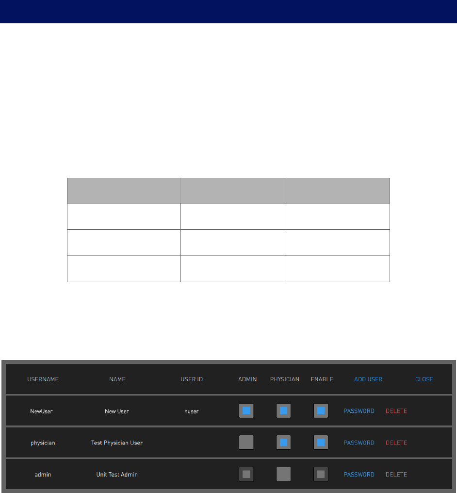
92 300-002547-00 rev7
User Administration
An Admin profile for the system will be created and provided to the site
administrator during system installation. The site administrator can create and
remove all user accounts and reset a user’s password if lost or forgotten. If a site
administrator loses the Admin password, contact Auris Customer Care for
password reset or recovery.
User Types
Specify a user’s access to create and perform a procedure, as well as
administration permission to manage other users.
Task Admin Physician
Create a procedure X
Perform a procedure X
Manage users X
Add New User
1. Log on as admin.
2. Select SETTINGS to view the Settings screen.
3. Select ADD USER. The following dialog box appears.
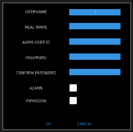
300-002547-00 rev7 93
4. Enter the following information for the new user:
USERNAME: a user name should be more than one character and be
unique.
REAL NAME
AURIS USER ID: the user ID provided by Auris Health, Inc.
PASSWORD: a password should have at least 12 characters and contain
at least one uppercase letter, one lowercase letter, one number, and one
special character/symbol.
CONFIRM PASSWORD
5. Select whether the user rights include ADMIN or PHYSICIAN or both.
6. Select OK to save.
7. Click CLOSE to exit the Settings screen.
Change User Password
If You Have Security Access to Other User Accounts
1. Log on as admin.
2. Select SETTINGS to view the Settings screen. A user list will populate for
current users.
3. Select PASSWORD in the row of the user profile whose password needs to
be changed. The following dialog box appears.
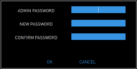
94 300-002547-00 rev7
4. Enter the following information:
ADMIN PASSWORD.
NEW PASSWORD: a password should have at least 12 characters and
contain at least one uppercase letter, one lowercase letter, one number,
and one special character/symbol.
CONFIRM PASSWORD.
5. To save your changes, select OK.
If You Have Security Access to Your Account Only
1. Log on.
2. Select SETTINGS to view the Settings screen.
3. Enter the following information:
NEW PASSWORD: a password should have at least 12 characters and
contain at least one uppercase letter, one lowercase letter, one number,
and one symbol.
CONFIRM PASSWORD.
4. To save your changes, select OK.
Disable Existing User
1. Log on as admin.
2. Select SETTINGS to view the Settings screen.
3. Find the user that you want to disable and clear the ENABLE box.
4. Select OK to confirm that you want to disable the user.

300-002547-00 rev7 95
System Security
Virus Protection
The Monarch Platform is built on a hardened Ubuntu Linux kernel, with strict user
permissions set up. Only qualified Auris field service technicians have the
required permissions to install software on the Monarch Platform.
Patient Data Security
The Monarch Platform fully encrypts all Patient Health Information (PHI) at rest
utilizing the Botan library, using the Advance Encryption Standard AES - 256.
This applies to all internal hard drives as well as any plans that users create and
transfer via Monarch USB drives.
Networking
Firewall
The Monarch Platform utilizes the Ubuntu firewall, blocking all inbound
connections, outbound connections, https, and DNS. One port is open to allow
outbound data extraction.
Internet Connectivity
The Monarch Platform has the ability to send case information to the Auris data
lake. The Auris system de-identifies all PHI from the case data before it is sent to
the Auris data lake. Additionally, the connection that is utilized to send the
information to the Auris data lake follows a well-architected framework and is
communicated via 256-bit encrypted SSL.
96 300-002547-00 rev7

300-002547-00 rev7 97
Troubleshooting
Fault Messages and Troubleshooting ....................................................................... 98

98 300-002547-00 rev7
Fault Messages and Troubleshooting
If any fault messages are unable to be cleared, remove the Bronchoscope
System and reboot the system. When rebooting the system, the user must
realign the cart to the patient introducer via the setup steps described previously.
If the user removes the bronchoscope while the robot arms are positioned for
scope insertion, the robot cart will need to be moved so that the scopes can be
attached to the robot arms outside of the patient. Once seated, reposition the
robot arms for scope insertion and continue procedure.
Emergency Removal
• If for any reason you need to remove the Monarch Bronchoscope System
quickly from the patient, remove the handles from the IDMs to relax the
Bronchoscope System and immediately remove the bronchoscope and
sheath.
• If you need to quickly access the endotracheal tube remove the
Bronchoscope Swivel Adapter from the Bronchoscope Patient Introducer to
facilitate direct access.
• If the Monarch Cart impedes access to the patient, mobilize the cart by lifting
the foot pedal and wheel it away from the patient.
E-Stop Recovery
1. Unload the Monarch Bronchoscope System.
2. Disengage the emergency stop button.
3. Click OK on the tower or cart user interface.
4. Reload the scope and re-initialize navigation, following the instructions on the
tower user interface.
Joystick Articulations Not Matching Directionally
1. Unload and load the scopes.
2. If the problem persists, replace the Monarch Bronchoscope System and/or
reboot the system.
Controller Does Not Appear Functional
1. Check the Monarch Controller pause/play button to ensure that it is available.
2. Check the Tower user interface to ensure that the screen shows the
Controller is active.
300-002547-00 rev7 99
3. Load and unload the handles from the robotic arms.
4. Reboot the system.
5. If the problem persists, contact Auris Customer Care for support.
Field Generator or Patient Introducer Mount Clamps Do
Not Tighten
1. Detach the mount from the table.
2. Inspect the clamp for fluid residue or debris blocking the clamp. Do not
disassemble the clamp to inspect.
3. Exercise the clamp by loosening and tightening the knobs.
4. If the knobs cannot be tightened, contact Auris Customer Care for a
replacement mount.
Monarch Platform Will Not Turn On
1. Confirm that the Monarch Tower and Cart main power cables are connected
to dedicated power outlets.
2. Confirm that the dedicated power outlets are active.
3. Confirm that the umbilical cable is connected to the Cart.
4. Press the power button on either the Tower or Cart. The light ring around the
power buttons will illuminate when the system is turned on.
5. If the Tower and Cart are connected to active power outlets, the umbilical
cable is connected to the Cart, and the system cannot be powered on using
either the Tower or Cart power buttons, contact Auris Customer Care for
support.
Tower and Cart Do Not Turn On Simultaneously
1. Confirm that the Monarch Tower and Cart main power cables are connected
to dedicated power outlets.
2. Confirm that the dedicated power outlets are active.
3. Confirm that the umbilical cable is connected to the Cart.
If the umbilical cable is not connected to the Cart:
a. Turn off the system.
b. Connect the umbilical cable.
c. Turn on the system.
100 300-002547-00 rev7
4. Confirm that the light rings around the Tower and Cart power buttons are
illuminated. If only one power button is illuminated, disconnect the umbilical
cable and press and hold the power button on the Tower/Cart to turn off.
5. Once the Tower and Cart are both turned off (power button light rings are not
illuminated), reconnect the umbilical cable to the Cart.
6. Turn on the system.
7. If problem persists, contact Auris Customer Care for support.
Video (Start Screen) Does Not Appear on Tower and Cart
Monitor After System Turns On
1. Confirm that light rings on Tower and Cart power buttons are illuminated.
2. If within a few minutes of turning on the system, the Start screen does not
appear on the Tower and Cart monitors, reboot the system.
3. If problem persists, contact Auris Customer Care for support.
Loss of Video on Tower or Cart Touchscreen (During
Procedure)
1. Confirm that light rings on tower and cart power buttons are illuminated.
2. Remove instruments inserted in the working channel of the Bronchoscope
System.
3. Use the Monarch Controller to relax and then retract the Bronchoscope
System.
4. Disconnect the Bronchoscope System from the robotic arms.
5. Reboot the system.
6. If tower and cart video are not present after system reboot, contact Auris
Customer Care for support.
Navigation Patient Sensors Not Detected During Setup
1. Confirm that sensors are placed on the patient within the Field Generator’s
field of view.
2. Slightly shift the location of the Field Generator to see if the sensor positions
change on the setup screen. If the position of the sensors appears to move
on the setup screen, the patient sensor and field generator positions may
need to be adjusted to bring all sensors into view.
3. Detach and reconnect the Navigation Patient Sensor cable on the Tower
connector.
300-002547-00 rev7 101
4. Move the cable to the opposite connector on the Tower.
5. If problem persists, contact Auris Customer Care for support.
CT Scan or Pre-Planned Case Cannot be Uploaded to
Tower
1. Reseat disc in DVD player or Monarch USB drive.
2. Confirm if the export button becomes available on the Patient List screen.
3. If problem persists, contact Auris Customer Care for support.
Keyboard on Planning Laptop Is Unresponsive
1. Reboot laptop.
2. If problem persists, contact Auris Customer Care for support.
Planning Laptop Will Not Turn On
1. Confirm laptop is connected to power.
2. If problem persists, contact Auris Customer Care for support.
Unable to Log on to Physician User Account on Tower or
Planning Laptop
1. Reboot system and log on.
2. If problem persists, contact hospital admin user for password reset.
Unable to Log on to Admin User Account on Tower or
Planning Laptop
1. Reboot system and log on.
2. If problem persists, contact Auris Customer Care for support.
102 300-002547-00 rev7

300-002547-00 rev7 103
Errors and Messages
System Messages ................................................................................................... 104

104 300-002547-00 rev7
System Messages
The Monarch Platform software constantly monitors system status and reports
any error conditions that may trigger a notification. The tables in this appendix
include errors, messages, and recommended actions for the Monarch Platform.
Table 1
ID Description Message
0 Config server error A system error has occurred and all robotic
functions have been disabled. Press OK to
continue. If problem persists, contact Auris
support.
1 Lost SlaveApp Heartbeat A system error has occurred. All robotic functions
have been disabled. To resolve, unload then
reload the Bronchoscope System and click OK to
acknowledge the fault. Then, re-initialize
navigation at the main carina.
2 Master heartbeat timeout. A system error has occurred. All robotic functions
have been disabled. To resolve, unload then
reload the Bronchoscope System and click OK to
acknowledge the fault. Then, re-initialize
navigation at the main carina.
2 Instrument Manager Timed Out A system error has occurred. All robotic functions
have been disabled. Unload the Bronchoscope
System and reboot the system. If problem
persists, contact Auris support.
3 System Error A system error has occurred and all robotic
functions have been disabled. Press OK to
continue. If problem persists, contact Auris
support.
4 System Error A system error has occurred and all robotic
functions have been disabled. Press OK to
continue. If problem persists, contact Auris
support.

300-002547-00 rev7 105
ID Description Message
5 Nav Error A system error has occurred and all robotic
functions have been disabled. Press OK to
continue. If problem persists, contact Auris
support.
6 Nav Error A system error has occurred and all robotic
functions have been disabled. Press OK to
continue. If problem persists, contact Auris
support.
7 Nav Error A system error has occurred and all robotic
functions have been disabled. Press OK to
continue. If problem persists, contact Auris
support.
8 System Error A system error has occurred and all robotic
functions have been disabled. Press OK to
continue. If problem persists, contact Auris
support.
9 System Error A system error has occurred and all robotic
functions have been disabled. Press OK to
continue. If problem persists, contact Auris
support.
100 System Error A system error has occurred and all robotic
functions have been disabled. Press OK to
continue. If problem persists, contact Auris
support.
101 Auto Bring-up failure A system error has occurred. All robotic functions
have been disabled. To resolve, unload then
reload the Bronchoscope System and click OK to
acknowledge the fault. Then, re-initialize
navigation at the main carina.
103 Configuration Server Failure A system error has occurred. All robotic functions
have been disabled. Unload the Bronchoscope
System and reboot the system. If problem
persists, contact Auris Technical support.

106 300-002547-00 rev7
ID Description Message
104 System Error A system error has occurred and all robotic
functions have been disabled. Press OK to
continue. If problem persists, contact Auris
support.
105 The Cart is disconnected from
the Tower. Please make sure
the Cart is connected to the
Tower.
A system error has occurred. All robotic functions
have been disabled. Unload the Bronchoscope
System and reboot the system. If problem
persists, contact Auris support.
107 SlaveApp Restart detected A system error has occurred. All robotic functions
have been disabled. To resolve, unload then
reload the Bronchoscope System and click OK to
acknowledge the fault. Then, re-initialize
navigation at the main carina.
108 EndoConsole restart detected A system error has occurred. All robotic functions
have been disabled. To resolve, unload then
reload the Bronchoscope System and click OK to
acknowledge the fault. Then, re-initialize
navigation at the main carina.
200 Sheath insertion force limit Sheath insertion force limit has been reached.
Check the sheath and arm alignment to the
patient introducer, check the device lubrication,
and clear the insertion pathway. Press OK to
continue.
201 Scope insertion force limit Bronchoscope insertion force limit has been
reached. Retract and visually inspect the device
for damage and kinks. Lubricate as necessary
prior to reinsertion. Press OK and initialize
navigation at the main carina.
202 High sheath insertion force has been detected.
203 High bronchoscope insertion force has been
detected.
204 Bronchoscope insertion limit has been reached.

300-002547-00 rev7 107
ID Description Message
205 Bronchoscope retraction limit has been reached.
206 Sheath insertion limit has been reached its limit.
207 Sheath retraction limit has been reached.
208 Sheath insertion limit has been reached.
209 Bronchoscope System loading
error
The Bronchoscope System failed to load
properly. Unload and reload the device.
210 Tensioning error The Bronchoscope System failed to load
properly. Unload and reload the device.
212 Bronchoscope articulation limit has been
reached.
213 Robot collision An arm collision has been detected, remove
obstructions to proceed. Press OK to continue.
214 Potential Collision Detection A system error has occurred. All robotic functions
have been disabled. To resolve, unload then
reload the Bronchoscope System and click OK to
acknowledge the fault. Then, re-initialize
navigation at the main carina.
215 Wire break detection Bronchoscope System wire breakage has been
detected. Unload and replace the device.
217 Instrument Still Loaded A system error has occurred. All robotic functions
have been disabled. To resolve, unload then
reload the Bronchoscope System and click OK to
acknowledge the fault. Then, re-initialize
navigation at the main carina.

108 300-002547-00 rev7
ID Description Message
221 Invalid command A system error has occurred. All robotic functions
have been disabled. To resolve, unload then
reload the Bronchoscope System and click OK to
acknowledge the fault. Then, re-initialize
navigation at the main carina.
300 Robot joint limit desired A system error has occurred. All robotic functions
have been disabled. To resolve, unload then
reload the Bronchoscope System and click OK to
acknowledge the fault. Then, re-initialize
navigation at the main carina.
301 Robot joint limit actual A system error has occurred. All robotic functions
have been disabled. To resolve, unload then
reload the Bronchoscope System and click OK to
acknowledge the fault. Then, re-initialize
navigation at the main carina.
302 Actual Velocity Threshold
Robot joint actual velocity
limit
A system error has occurred. All robotic functions
have been disabled. To resolve, unload then
reload the Bronchoscope System and click OK to
acknowledge the fault. Then, re-initialize
navigation at the main carina.
303 Robot joint actual acceleration
limit
A system error has occurred. All robotic functions
have been disabled. To resolve, unload then
reload the Bronchoscope System and click OK to
acknowledge the fault. Then, re-initialize
navigation at the main carina.
304 Desired Velocity Threshold
Robot joint desired velocity
limit
A system error has occurred. All robotic functions
have been disabled. To resolve, unload then
reload the Bronchoscope System and click OK to
acknowledge the fault. Then, re-initialize
navigation at the main carina.
305 Robot joint desired acceleration
limit
A system error has occurred. All robotic functions
have been disabled. To resolve, unload then
reload the Bronchoscope System and click OK to
acknowledge the fault. Then, re-initialize
navigation at the main carina.

300-002547-00 rev7 109
ID Description Message
306 Robot joint actual torque limit A system error has occurred. All robotic functions
have been disabled. To resolve, unload then
reload the Bronchoscope System and click OK to
acknowledge the fault. Then, re-initialize
navigation at the main carina.
307 Elmo Axis Following Error
Tracking error
A system error has occurred. All robotic functions
have been disabled. To resolve, unload then
reload the Bronchoscope System and click OK to
acknowledge the fault. Then, re-initialize
navigation at the main carina.
308 Axis Power Error A system error has occurred. All robotic functions
have been disabled. To resolve, unload then
reload the Bronchoscope System and click OK to
acknowledge the fault. Then, re-initialize
navigation at the main carina.
309 Axis Error A system error has occurred. All robotic functions
have been disabled. To resolve, unload then
reload the Bronchoscope System and click OK to
acknowledge the fault. Then, re-initialize
navigation at the main carina.
310 Actual Current A system error has occurred. All robotic functions
have been disabled. To resolve, unload then
reload the Bronchoscope System and click OK to
acknowledge the fault. Then, re-initialize
navigation at the main carina.
311 Encoder mismatch A system error has occurred. All robotic functions
have been disabled. Unload the Bronchoscope
System and reboot the system. If problem
persists, contact Auris support.
400 IDM Fault A system error has occurred. All robotic functions
have been disabled. To resolve, unload then
reload the Bronchoscope System and click OK to
acknowledge the fault. Then, re-initialize
navigation at the main carina.

110 300-002547-00 rev7
ID Description Message
402 Robot IDM power up A system error has occurred and all robotic
functions have been disabled. Press OK to
continue. If problem persists, contact Auris
support.
403 IDM Velocity A system error has occurred. All robotic functions
have been disabled. To resolve, unload then
reload the Bronchoscope System and click OK to
acknowledge the fault. Then, re-initialize
navigation at the main carina.
406 System temperature has exceeded its limit.
407 IDM Max Temperature
Exceeded
A system error has occurred. All robotic functions
have been disabled. To resolve, unload then
reload the Bronchoscope System and click OK to
acknowledge the fault. Then, re-initialize
navigation at the main carina.
408 Kinova FW Mismatch A system error has occurred. All robotic functions
have been disabled. Unload the Bronchoscope
System and reboot the system. If problem
persists, contact Auris support.
409 Tension Threshold Exceeded A system error has occurred. All robotic functions
have been disabled. To resolve, unload then
reload the Bronchoscope System and click OK to
acknowledge the fault. Then, re-initialize
navigation at the main carina.
500 Robot controller error A system error has occurred. All robotic functions
have been disabled. To resolve, unload then
reload the Bronchoscope System and click OK to
acknowledge the fault. Then, re-initialize
navigation at the main carina.

300-002547-00 rev7 111
ID Description Message
501 Robot controller comm timeout A system error has occurred. All robotic functions
have been disabled. To resolve, unload then
reload the Bronchoscope System and click OK to
acknowledge the fault. Then, re-initialize
navigation at the main carina.
504 Robot Controller Status Frozen A system error has occurred. All robotic functions
have been disabled. Unload the Bronchoscope
System and reboot the system. If problem
persists, contact Auris support.
505 Robot control loop disabled A system error has occurred. All robotic functions
have been disabled. To resolve, unload then
reload the Bronchoscope System and click OK to
acknowledge the fault. Then, re-initialize
navigation at the main carina.
506 Robot controller ESTOP The E-stop has been activated. All robotic
functions have been disabled. To resolve,
release the E-stop button, then unload and reload
the Bronchoscope System. Lastly, re-initialize
navigation at the main carina.
600 Staging Error A system error has occurred. All robotic functions
have been disabled. To resolve, unload then
reload the Bronchoscope System and click OK to
acknowledge the fault. Then, re-initialize
navigation at the main carina.
601 Staging Velocity A system error has occurred. All robotic functions
have been disabled. To resolve, unload then
reload the Bronchoscope System and click OK to
acknowledge the fault. Then, re-initialize
navigation at the main carina.
602 Staging Initialization A system error has occurred. All robotic functions
have been disabled. To resolve, unload then
reload the Bronchoscope System and click OK to
acknowledge the fault. Then, re-initialize
navigation at the main carina.

112 300-002547-00 rev7
ID Description Message
603 Staging Power up A system error has occurred. All robotic functions
have been disabled. To resolve, unload then
reload the Bronchoscope System and click OK to
acknowledge the fault. Then, re-initialize
navigation at the main carina.
604 Staging Axis FW Mismatch A system error has occurred. All robotic functions
have been disabled. Unload the Bronchoscope
System and reboot the system. If problem
persists, contact Auris support.
605 Cart not properly immobilized A system error has occurred. All robotic functions
have been disabled. To resolve, unload then
reload the Bronchoscope System and click OK to
acknowledge the fault. Then, re-initialize
navigation at the main carina.
700 Camera thread has failed to be
setup.
A system error has occurred. All robotic functions
have been disabled. Unload the Bronchoscope
System and reboot the system. If problem
persists, contact Auris support.
701 A system error has occurred. All robotic functions
have been disabled. Unload the Bronchoscope
System and reboot the system. If problem
persists, contact Auris support.
702 A system error has occurred. All robotic functions
have been disabled. Unload the Bronchoscope
System and reboot the system. If problem
persists, contact Auris support.
703 A system error has occurred. All robotic functions
have been disabled. Unload the Bronchoscope
System and reboot the system. If problem
persists, contact Auris support.
705 Could not preform file operation A system error has occurred. All robotic functions
have been disabled. Unload the Bronchoscope
System and reboot the system. If problem
persists, contact Auris support.

300-002547-00 rev7 113
ID Description Message
706 A system error has occurred. All robotic functions
have been disabled. Unload the Bronchoscope
System and reboot the system. If problem
persists, contact Auris support.
707 Camera frame rate issue detected. Check
camera visibility.
708 Camera frame rate issue detected. Check
camera visibility.
709 Failed to initialize camera. A system error has occurred. All robotic functions
have been disabled. Unload the Bronchoscope
System and reboot the system. If problem
persists, contact Auris support.
710 Failed to read image. A system error has occurred. All robotic functions
have been disabled. Unload the Bronchoscope
System and reboot the system. If problem
persists, contact Auris support.
711 Scope disconnected Warning: The bronchoscope cable has been
disconnected. Live Bronchoscope view is
unavailable and may lead to patient injury.
Reconnect the cable and press OK to continue.
712 Image frozen Warning: The bronchoscope image is frozen and
the system has been halted to prevent patient
injury. Press OK to continue and if problem
persists, replace the bronchoscope system or
contact Auris support.
713 Camera FPGA FW or HW
Version Mismatch
A system error has occurred. All robotic functions
have been disabled. Unload the Bronchoscope
System and reboot the system. If problem
persists, contact Auris support.

114 300-002547-00 rev7
ID Description Message
800 PDU EtherCAT Communication
Problem
A system error has occurred. All robotic functions
have been disabled. To resolve, unload then
reload the Bronchoscope System and click OK to
acknowledge the fault. Then, re-initialize
navigation at the main carina.
801 PDU Version Mismatch A system error has occurred. All robotic functions
have been disabled. Unload the Bronchoscope
System and reboot the system. If problem
persists, contact Auris support.
802 PDU Initialization Error A system error has occurred. All robotic functions
have been disabled. To resolve, unload then
reload the Bronchoscope System and click OK to
acknowledge the fault. Then, re-initialize
navigation at the main carina.
803 PDU Power Critical Error A system error has occurred. All robotic functions
have been disabled. Unload the Bronchoscope
System and reboot the system. If problem
persists, contact Auris support.
804 PDU EStop Error A system error has occurred. All robotic functions
have been disabled. To resolve, unload then
reload the Bronchoscope System and click OK to
acknowledge the fault. Then, re-initialize
navigation at the main carina.
805 System has switched to battery power. 5 minutes
remaining!
806 Battery System battery is running low! Connect to power
as soon as possible.
807 PDU Battery Critically Depleted A system error has occurred. All robotic functions
have been disabled. Unload the Bronchoscope
System and reboot the system. If problem
persists, contact Auris support.

300-002547-00 rev7 115
ID Description Message
900 Fluidics error A system error has occurred and all robotic
functions have been disabled. Press OK to
continue. If problem persists, contact Auris
support.
901 Fluidics Initialization Error A system error has occurred. All robotic functions
have been disabled. To resolve, unload then
reload the Bronchoscope System and click OK to
acknowledge the fault. Then, re-initialize
navigation at the main carina.
902 Fluidics pump error An irrigation pump error has been detected.
Press OK to continue.
903 Fluidics valve error An aspiration pinch valve error has been
detected. Press OK to continue
904 Fluidics max volume Saline delivery threshold has been reached.
Press OK to continue.
1000 Pendant non-recoverable
hardware fault
A system error has occurred. All robotic functions
have been disabled. To resolve, unload then
reload the Bronchoscope System and click OK to
acknowledge the fault. Then, re-initialize
navigation at the main carina.
1001 Controller HW error The endoscopic controller has detected a drop or
upside-down placement and all robotic functions
have been paused. Press the play button on the
controller to make functionality available again.
Press OK to continue.
1002 Pendant Revision Fault
Pendant Revision does not
match
A system error has occurred. All robotic functions
have been disabled. To resolve, unload then
reload the Bronchoscope System and click OK to
acknowledge the fault. Then, re-initialize
navigation at the main carina.

116 300-002547-00 rev7
ID Description Message
1003 Pendant Software Fault
Pendant control software
fault
A system error has occurred. All robotic functions
have been disabled. To resolve, unload then
reload the Bronchoscope System and click OK to
acknowledge the fault. Then, re-initialize
navigation at the main carina.
1004 Pendant Communication
Pendant communication
fault
A system error has occurred. All robotic functions
have been disabled. To resolve, unload then
reload the Bronchoscope System and click OK to
acknowledge the fault. Then, re-initialize
navigation at the main carina.
1100 EM device fault A system error has occurred. All robotic functions
have been disabled. To resolve, unload then
reload the Bronchoscope System and click OK to
acknowledge the fault. Then, re-initialize
navigation at the main carina.
1101 EM device communication fault A system error has occurred. All robotic functions
have been disabled. To resolve, unload then
reload the Bronchoscope System and click OK to
acknowledge the fault. Then, re-initialize
navigation at the main carina.
1102 EM device revision match not
found
A system error has occurred. All robotic functions
have been disabled. To resolve, unload then
reload the Bronchoscope System and click OK to
acknowledge the fault. Then, re-initialize
navigation at the main carina.
1103 Scope configuration data invalid A system error has occurred. All robotic functions
have been disabled. To resolve, unload then
reload the Bronchoscope System and click OK to
acknowledge the fault. Then, re-initialize
navigation at the main carina.
1105 EM software fault A system error has occurred. All robotic functions
have been disabled. To resolve, unload then
reload the Bronchoscope System and click OK to
acknowledge the fault. Then, re-initialize
navigation at the main carina.

300-002547-00 rev7 117
ID Description Message
1200 Nav scope EM quality Poor quality navigation field generator data
detected. Navigation accuracy may be
compromised. Press OK to continue.
1201 Poor quality image detected. Navigation may be
compromised.
1202 Poor quality EM data detected. Navigation may
be compromised.
1203 Nav error A navigation error has been detected. Navigation
accuracy may be compromised. Press OK to
continue.
1204 Navigation error detected. Navigation may be
compromised.
1205 Nav initialization error A navigation initialization error has occurred.
Repeat initialization.
1206 Nav initialization error Insufficient EM data for navigation initialization.
Repeat initialization.
1208 EM distortion has been detected. Navigation may
be compromised.
1209 Field generator or patient sensor motion has
been detected.
1210 Patient or FG motion Navigation field generator and/or patient
movement has been detected. Navigation
accuracy may be compromised. Visually inspect
the navigation field generator and/or patient
sensor positioning and initialize navigation at the
main carina.
1211 Nav retraction outside trachea The bronchoscope tip location is outside of the
segmented trachea. Move the bronchoscope tip
closer to the main carina and initialize navigation.
1212 Bronchoscope buckling has been detected.
Check bronchoscope.

118 300-002547-00 rev7
ID Description Message
1213 Scope buckling Bronchoscope buckling has been detected.
Retract and visually inspect the Bronchoscope
System for damage or kinks. Lubricate as
necessary prior to reinsertion. Press OK and
initialize navigation at the main carina.
1214 Nav EM registration error An EM error has been detected. Repeat
navigation initialization. If problem persists,
contact Auris support.
1215 Nav contralateral registration Contralateral registration failed. Repeat
navigation initialization.
1216 Navigation latency detected. Navigation may be
compromised.
1217 Navigation error detected. Navigation may be
compromised.
1300 Bronchoscope System loading
error
The Bronchoscope System failed to load
properly. Unload and reload the device.
1301 Instrument Manager FW
Mismatch
A system error has occurred. All robotic functions
have been disabled. Unload the Bronchoscope
System and reboot the system. If problem
persists, contact Auris support.
1401 EtherCAT Missing Frame(s)
Over Max Limit
A system error has occurred. All robotic functions
have been disabled. To resolve, unload then
reload the Bronchoscope System and click OK to
acknowledge the fault. Then, re-initialize
navigation at the main carina.
1402 EtherCAT Jitter Over Max Limit A system error has occurred. All robotic functions
have been disabled. To resolve, unload then
reload the Bronchoscope System and click OK to
acknowledge the fault. Then, re-initialize
navigation at the main carina.

300-002547-00 rev7 119
ID Description Message
1403 Critical EtherCAT fault
EtherCAT Initialization
Failure
A system error has occurred. All robotic functions
have been disabled. Unload the Bronchoscope
System and reboot the system. If problem
persists, contact Auris support.
1500 Inverse Kinematics Failed A system error has occurred. All robotic functions
have been disabled. To resolve, unload then
reload the Bronchoscope System and click OK to
acknowledge the fault. Then, re-initialize
navigation at the main carina.
2000 DAQ communication fault A system error has occurred. All robotic functions
have been disabled. Unload the Bronchoscope
System and reboot the system. If problem
persists, contact Auris support.
2001 DAQ communication fault A system error has occurred. All robotic functions
have been disabled. Unload the Bronchoscope
System and reboot the system. If problem
persists, contact Auris support.
2002 DAQ communication fault A system error has occurred. All robotic functions
have been disabled. Unload the Bronchoscope
System and reboot the system. If problem
persists, contact Auris support.
2004 Linear slide comm error A system error has occurred. All robotic functions
have been disabled. Unload the Bronchoscope
System and reboot the system. If problem
persists, contact Auris support.
2005 System Error A system error has occurred and all robotic
functions have been disabled. Press OK to
continue. If problem persists, contact Auris
support.
2007 Invalid SW Revision A system error has occurred. All robotic functions
have been disabled. Unload the Bronchoscope
System and reboot the system. If problem
persists, contact Auris support.

120 300-002547-00 rev7
ID Description Message
2009 PDU not running A system error has occurred. All robotic functions
have been disabled. Unload the Bronchoscope
System and reboot the system. If problem
persists, contact Auris support.
2010 A system error has occurred. All robotic functions
have been disabled. Unload the Bronchoscope
System and reboot the system. If problem
persists, contact Auris support.
2011 DAQ Comm Fault A system error has occurred. All robotic functions
have been disabled. Unload the Bronchoscope
System and reboot the system. If problem
persists, contact Auris support.
2012 Flush Aspiration Valves Error A system error has occurred. All robotic functions
have been disabled. Unload the Bronchoscope
System and reboot the system. If problem
persists, contact Auris support.
2013 Syringe Pump Error A system error has occurred. All robotic functions
have been disabled. Unload the Bronchoscope
System and reboot the system. If problem
persists, contact Auris support.
2014 Peristaltic Pump Error A system error has occurred. All robotic functions
have been disabled. Unload the Bronchoscope
System and reboot the system. If problem
persists, contact Auris support.
2015 Linear slide not working right. A system error has occurred. All robotic functions
have been disabled. Unload the Bronchoscope
System and reboot the system. If problem
persists, contact Auris support.
2016 Force sensor comm error A system error has occurred. All robotic functions
have been disabled. Unload the Bronchoscope
System and reboot the system. If problem
persists, contact Auris support.

300-002547-00 rev7 121
ID Description Message
2019 DofLimit A system error has occurred. All robotic functions
have been disabled. Unload the Bronchoscope
System and reboot the system. If problem
persists, contact Auris support.
2020 IterationLimit A system error has occurred. All robotic functions
have been disabled. Unload the Bronchoscope
System and reboot the system. If problem
persists, contact Auris support.
Table 2
The following indicates a variable in the message, such as a number (case ID) or
text (file name): “%1”.
Category Description
System message
Robot Initializing...
By pressing Approve, you are acknowledging
review and approval of this plan for use.
Do you also want to export the video?
Do you want to shut down the system?
The CT data is more than 30 days old. Ensure the
CT data reflects the current patient anatomy
accurately.
%1 already exists on the system. Would you like to
overwrite it?
Import %1?
Permanently delete %1?
This patient case was previously imported and
cannot be imported again
Approximately %1 space is available. To save new
cases, delete cases that are no longer needed.

122 300-002547-00 rev7
Category Description
System message
Successfully exported \"%1\"
Failed to export \"%1\"
There is not enough space available on the USB to
export the case.
Couldn't find \"%1\"
Directory \"%1\" does not exist.
Failed to import CT dataset. Re-insert the disk and
try again. If problem persists, contact Auris
support.
Failed to segment CT data. Retry segmentation. If
problem persists, contact Auris support.
System Error \"%1\" cannot be accessed, contact Auris support.