Aurum Electronics 939ASD-MIC Smart Guard Halogen Light User Manual
Aurum Electronics Corp. Smart Guard Halogen Light
User Manual
Manual Contents:
A. 939ASD kit contents
B. 939ASD overview
C. Definition
D. Programming your 939ASD
E. Mounting the 939ASD
F. Driver installation
G. Viewing image
H. Technical Specifications
I. General Information and Safety
J. FCC information
A. 939ASD kit contents
z Model 939ASD Lighting Camera
z Camera driver: CDROM driver for Windows 98/2000/XP
z User Manual
z 1M USB cable & 1G SD card
z Accessory bag: screws, wall plugs, 1pc allen key, 3pcs 1.5V AAA batteries
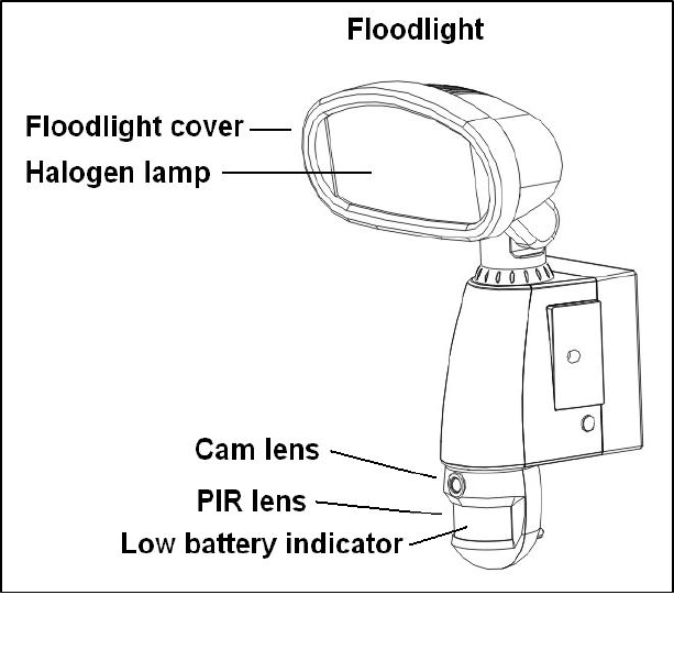
B. 939ASD overview
Fig. 1
C. Definition
1. Definition of front view parts (see fig. 1)
Floodlight cover:Open to replace a new halogen lamp.
Floodlight:For lighting purpose
Halogen lamp:For lighting purpose, please use the correct voltage and watts of halogen light for this
product. Halogen lamp, max power is 300W
Cam Lens:this is the digital camera lens, please use a soft cloth to clean if needed.
PIR lens:Passive Infrared Lens.
Low Battery Indicator (hidden inside the lens)
1) Red lamp will start to flash when the battery is going to be out of power.
2) If the battery is out of power, the date of system may be lost and cause the system abnormal.
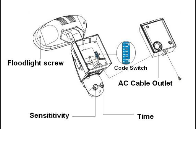
2. Definition of back view parts (see fig. 2)
Floodlight screw:Used to open or close the flood light case to install the halogen lamp.
Time control knob:For adjusting the illumination time of halogen floodlight power
Adjust to “-” where the minimal time is 40 seconds;adjust to “+” where the maximal time is 7 minutes.
Sensitivity control knob:Adjust to the range of Passive Infrared Motion Sensor where can be detected.
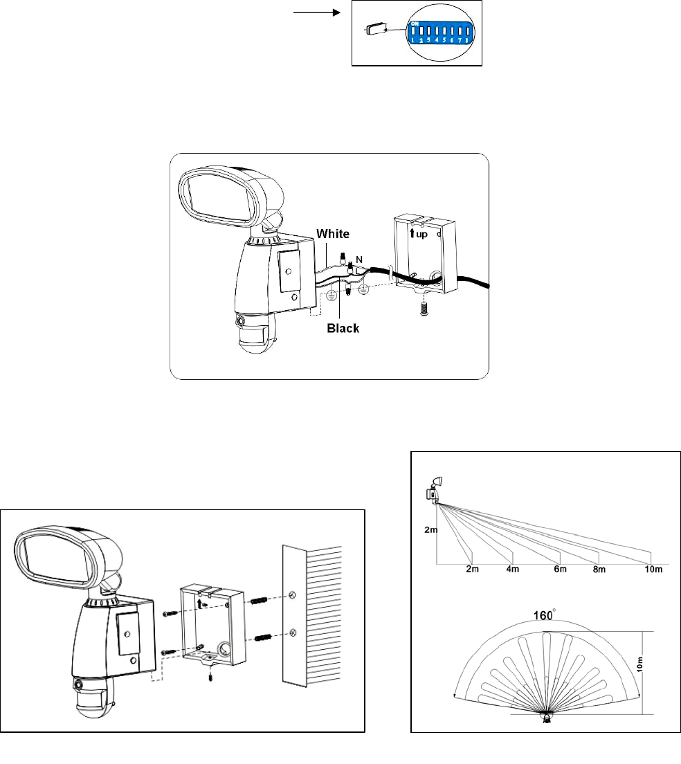
AC cable outlet:For connecting the external AC cable to 939ASD
8 Positions DIP switch:256 sets of changeable system code is available
1) To select a system code simply move some of the eight slider-switches in the RF transmitter
unit –leave some in their original position. This is now your system code; the slider-switches in your
RF receiver unit must now be set in the same pattern. Make a note of the settings on a piece of paper,
so you can double-check your code without having to re-open the RF transmitter unit.
2) Make sure the 8 Positions DIP switch of 939ASD is the same as the setting of receivers and remote control.
Fig. 2
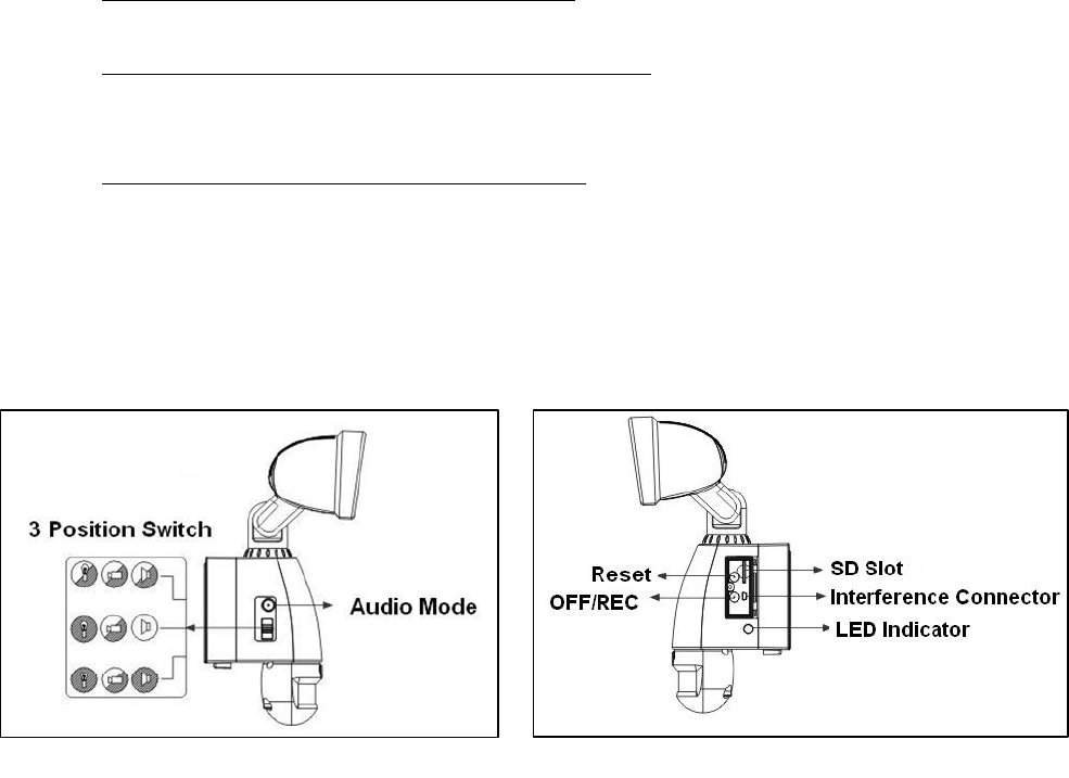
3. Definition of side view parts (see fig. 3 & 4)
3 position switch:for functions selection
1) Light + camera + speaker: detection for all day
Daytime and nighttime: light, camera and speaker are all in operation
2) Light at night + camera all day + speaker in the daytime
Daytime: light is off, camera is on, speaker is on
Nighttime: light is on, camera is on, speaker is off.
3) Light at night + camera all day + speaker at night
Daytime: light is off, camera is on, speaker is off.
Nighttime: light is on, camera is on, speaker is on.
Audio mode:for different sound selection
Pre-set default is “Welcome”. Push one time to ”May I help you”, push again to “dog barking”.
Push one more time to turn off this function. Control operates in above circular pattern.
LED indicator:for indicating the status of function or error situation by different color of LED
1) Red: SD card is not inserted into the SD slot or the system is abnormal
2) Green: 939ASD is recording or USB is inserted and connecting with the computer
3) LED off: stand by(SD card is inserted into the slot), when off button is pressed
* Please note when off button is pressed, remove SD card within 30 seconds (now the LED will turn
red after SD card is removed from the slot)
Waterproofed cover: protects below-listed contents.
Interference Connector:For connecting the 939ASD to PC by provided USB cable to PC.
SD slot:For inserting the memory card, please push the SD card to the end and make sure that it is
properly seated.
Reset button: restore functions to default settings
1) Press RESET button one time when turn on 939ASD
2) Please press this button if there is any abnormal situation happen.
Off/Rec:Please press OFF button to remove SD card. Please remove card within 30 seconds of
pressing the OFF button to avoid loss of data.
Fig. 3 Fig. 4
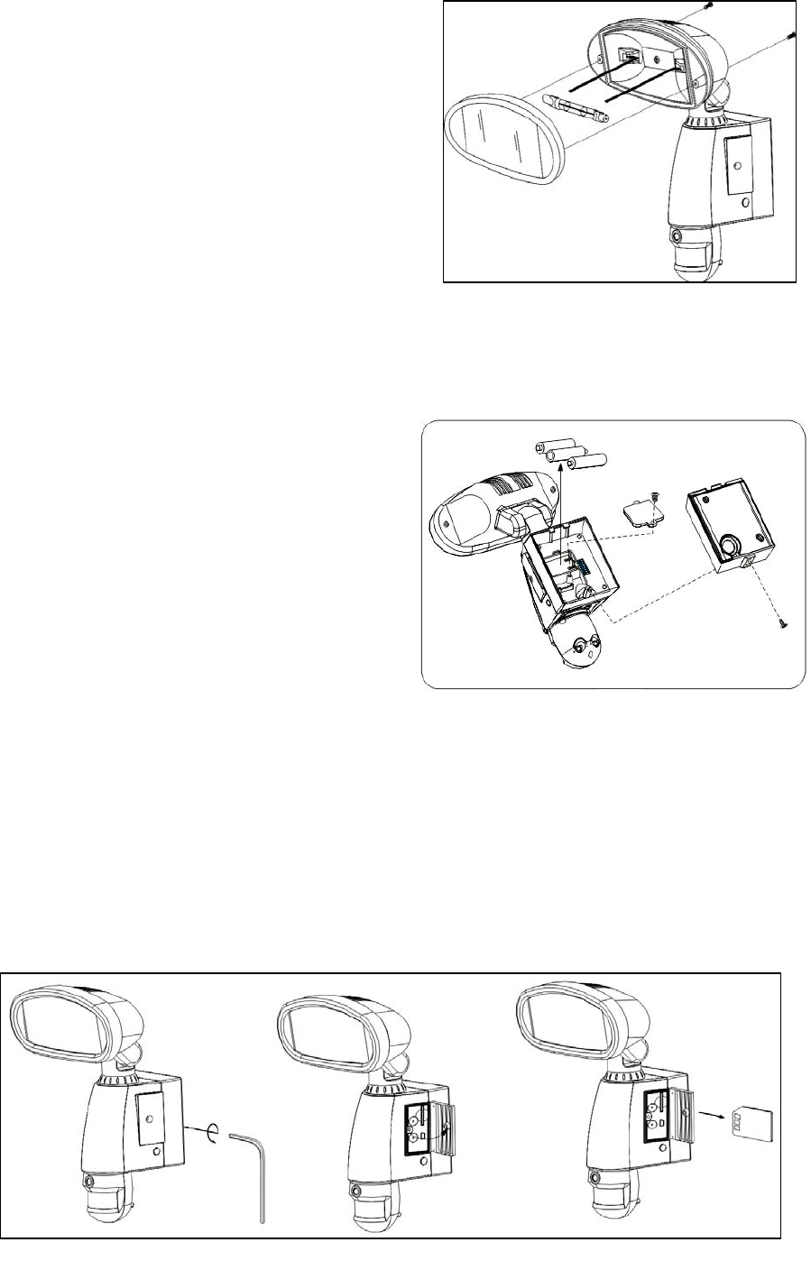
Fig.6
D. Programming your 939ASD
1. Install/replace the halogen lamp (see fig. 5)
Make sure to turn off the power of 939ASD or
discount the AC outlet
Open the floodlight from floodlight screw by screw
driver.
Take out the Halogen lamp.
Place a new Halogen lamp.
* Halogen Lamp is 300W
Close the floodlight with screw carefully
Please make sure the voltage and polarity are correct before connection.
Incorrect voltage will damage the camera. If you are not sure, please contact your retailer.
2. Install/replace batteries (see fig. 6)
Unscrew the back cover and unscrew the
battery cover.
Put the 3 provided AAA 1.5V batteries into the
batter compartment and make sure the polarity
(- +) is placed correctly.
Install battery cover and back cover.
3. Set the Data and Time:
Install the provided software to your PC
(For details, please see F. Driver Installation)
Plug provided USB cable from 939ASD to PC
Execute the program and click “Play”, when the video
is shown on the screen the setup is completed.
(The setup of time and date will be the same as computer)
Close the program and remove USB cable to complete the setup.
4. Insert/remove SD card(see fig. 7):
Unscrew the waterproofed cover by provided allen key, then insert the SD card and lock in place.
If you need to remove the SD card, please press OFF button and take it out within 30 seconds.
When LED lamp turns green, meaning SD card is being read, do not remove SD card or the data may
be lost.
Fig. 7
Fig.5
5. Other settings (see fig. 2)
Time control:Turn the time control knob to”+” side to increase the illumination time, turn the control
knob to “-“ side to reduce the illumination time.
Sensitivity control:Adjust the detector range of Passive Infrared Motion Sensor
8 Positions DIP switch:
1) This product is able to operate with RF wireless receivers. To select a system code simply move
some of the eight slider-switches in the RF transmitter unit – remove the rubber pad first and leave
some in their original position. This is now your system code; the slider-switches in your RF
receiver unit must now be set in the same pattern. Make a note of the settings on a piece of paper, so
you can double-check your code without having to re-open the RF transmitter unit.
2) Make sure the 8 Positions DIP switch of 939ASD is the same as the setting of receivers.
3) Put the rubber pad back to the switch.
E. Mounting the camera
1. Connect the 939ASD to AC power (see fig. 8)
Please make sure the voltage and polarity are correct before connection. Incorrect voltage will damage the
camera. If you are not sure, please contact your retailer.
Connect the AC cable with correct polarity. The 939ASD will turn on 1 min. for self-testing.
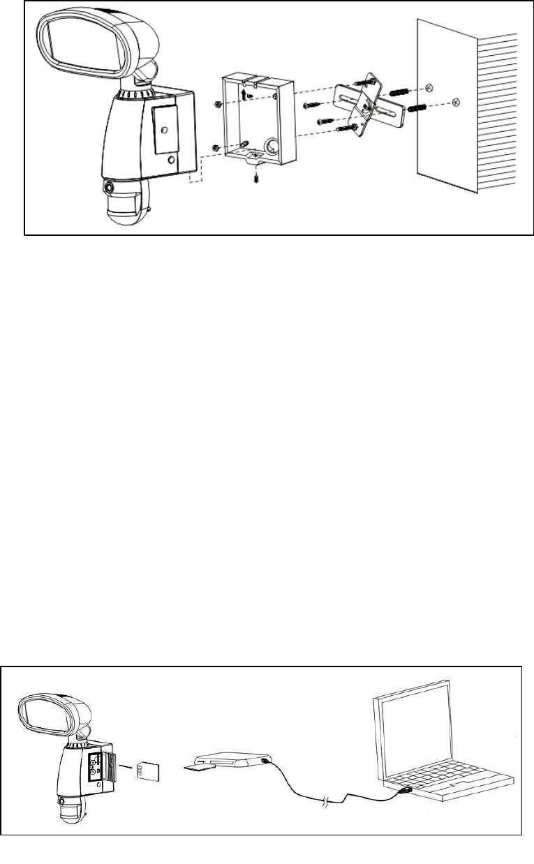
2. Mount the 939ASD to the wall by provided screws or crossbars (see fig.9.1 & 9.2)
It’s recommend to mount the lighting camera 2 M above the ground
Detection range: 10M x 160° (see fig. 10)
Fig. 10 Fig. 9.1
Fig. 8
F. Driver installation
Attention! The software CD-ROM packaged with the camera is designed for PC´s only (not available for
MAC). Playing this CD-ROM on a stereo or CD player may cause damage to it.
z Unplug the USB cable form PC
z Insert the CDROM in CD driver of your PC.
z The auto-run program will execute.
z Follow the instructions shown on screen form your PC to completely install the driver and application
program.
z Restart windows.
z If your computer doesn’t run automatically, please click “Start” button and choose “Run”, and then
browse the CD drive and click “Setup”.
G. Viewing image
1. Viewing image by computer through a card reader (see fig. 11)
Open the rubber cap on the 939ASD
Pushing the SD memory card to release to the SD card form 939ASD
Put the SD card to a card reader, then the captured image will display on the monitor of PC
2. Viewing image from 939ASD (see fig .12)
You should install the provided driver, please refer to above DRIVER INSTALLATION
Connect the provided USB cable from 939ASDto pc when 939ASD is power on.
Execute the provided software to watch the video.
Fig. 11
Fig. 9.2
3. Viewing image from universal card reader (see fig. 11)
Remove the SD card rubber cover.
Push in the SD card to eject SD card form 939ASD.
Insert the SD card to universal card reader.
You can view the captured image form PC through the card reader.
H. Technical Specifications
1. System Requirements and Compatibility:
Windows 98/98SE/2000/ME/XP.
Pentium III 450MHZ or equivalent processor.
128MB SDRAM or above.
VGA image Card with 32MB RAM for minimum, Color 16bit or higher.
CDROM driver and USB Port are available.
2.5GB free hard disc space.
If you have any questions regarding your PC specifications please call your PC manufacturer.
2. Features and specification:
PIR detection angle 160 Deg and detection range up to 10M
Color CMOS image Sensor 1.3MB Pixels.
Max Resolution:2.0MB pixels, 1600 x 1200 pixels by hardware interpolation
30 seconds image recording for image stream:15fps at 480*640 Pixels
Built in 1G SDRAM for image buffer and image storage
Built in SD card slot for SD memory card
SD Card slot for additional storage, max memory size up to 2G
Automatic exposure control, white balance and sharpness
Auto Date & Time stamp
High precision:1 Group
Effective viewing angle:48 deg
Built in USB plug for PC access
Interface type: USB 1.1
Image format: JPEG AVI File
Powered by AC 90V to 240V(subject to requirement)
Floodlight tube is 300W
Auto light sensor.
Fig. 12
Sensitivity control
Floodlight time delay control
Product measurements:(L) 190 x (W)180 x (H)315mm. Weight: 1.42
Battery: 1.5V AAA x 3pcs
I. General Information and safety
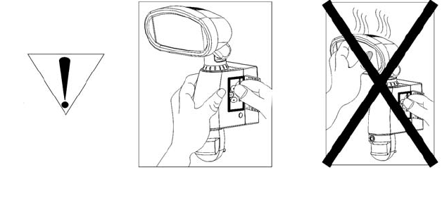
Special care instructions!!!
z The 939ASD is designed to be weather resistant. Never attempt to immerse the unit to water or any other
liquid. This will damage the unit and void the warranty.
z Use a soft lens cloth for cleaning lens. Avoid touching lens with fingers.
z Remove dirt or stains with a soft cloth dampened with water or neutral detergent. Keep the 939ASD in a
dry and cool dust-free environment or container when it is NOT used
z Do not open the 939ASD for unauthorized service. This could cause serious damage to the unit and will
void the warranty.
z This 939ASD is a precision electronic device. Do not attempt to service this camera yourself, as opening
or removing covers may expose you to the danger of electric shock or other risks.
z To avoid risk of burns due to high temperature do not touch the floodlight when it is turned on.
J. FCC Information
This device complies with Part 15 of the FCC Rules. Operation is subject to the following two conditions: (1) This device
may not cause harmful interference, and (2) This device must accept any interference received, including interference that
may cause undesired operation.
Warning: Changes or modification to this unit not expressly approved by the party responsible for compliance could void
the user’s authority to operate the equipment.
NOTE: This equipment has been tested and found to comply with the limited for Class B digital device, pursuant to Part
15 of the FCC Rules. Their limits are designed to provide reasonable protection against harmful interference in a
residential installation. This equipment generates, uses and can radiate radio frequency energy and, if not installed and
used in accordance with the instructions, may cause harmful interference to radio communications.
However, there is no guarantee that interference will not occur in a particular installation. If the equipment does cause
harmful interference to radio or television reception, which can be determined by turning the equipment off and on, the
user is encouraged to try to correct the interference by one or more of the following measures: Reorient or relocate the
receiving antenna.
Increase the separation between the equipment and receiver.
Connect the equipment into an outlet on a circuit different from that to which the receiver is connected.
Consult the dealer or an experienced radio/TV technician for help.
The equipment compliance with FCC radiation exposure limit set forth for uncontrolled Environment
Fig. 11
CAUTION!!!