Autel Intelligent Tech 1806-808BT Professional Scan Tool User Manual Uaser Manual
Autel Intelligent Tech. Corp., Ltd. Professional Scan Tool Uaser Manual
UserManual.wiki
>
Autel Intelligent Tech
>
1806-808BT User Manual
>
Uaser_Manual
Contents
1.
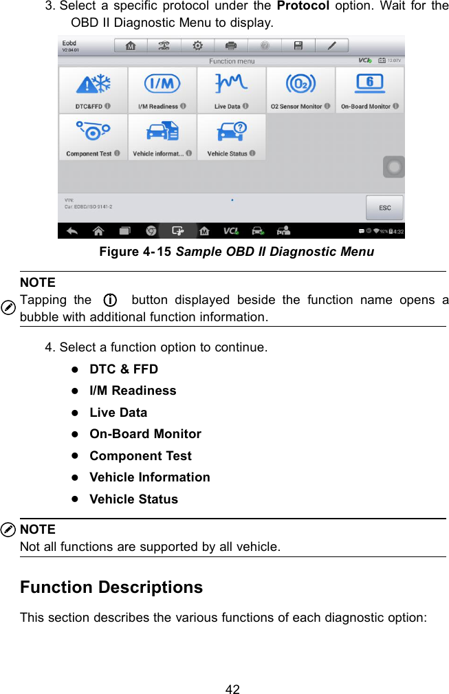
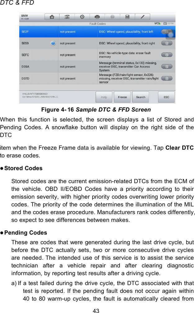
User Manual
2.
Uaser_Manual
Uaser_Manual
Navigation menu
Upload a User Manual
Namespaces
Wiki Guide
HTML
PDF
Info
Views
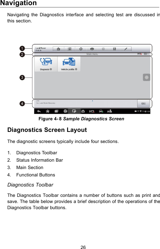
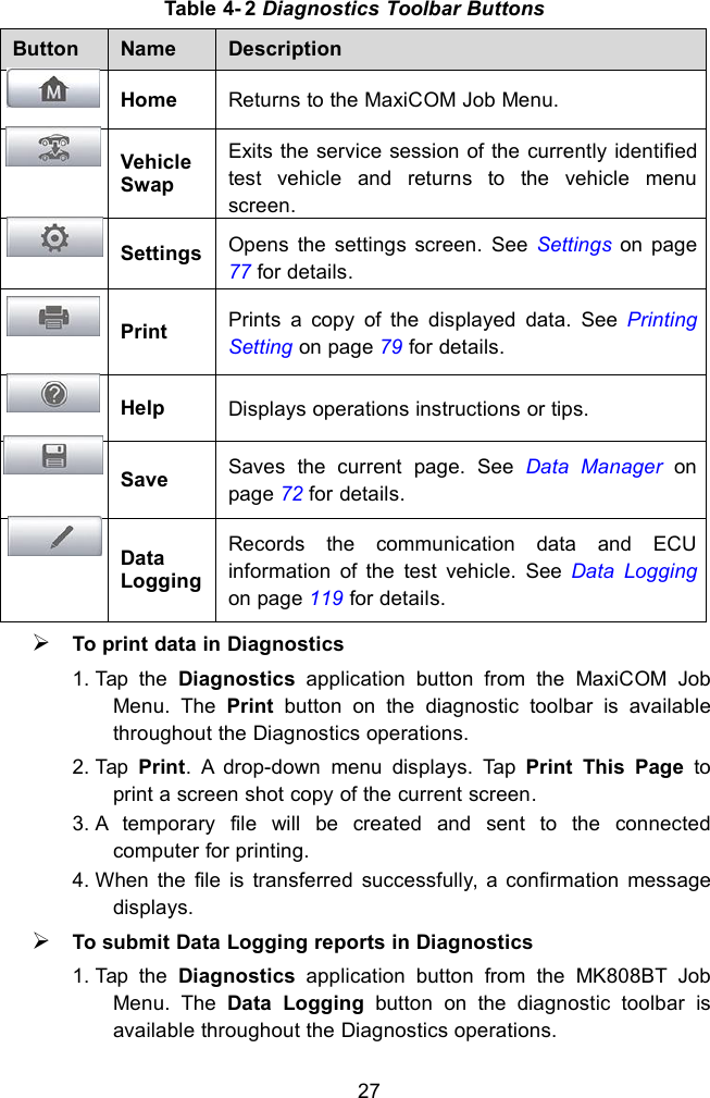
User Manual
Discussion / Help
Navigation