Autel Intelligent Tech 2012J2534 J2534 ECU Programming Device User Manual Table of Contents
Autel Intelligent Tech. Corp., Ltd. J2534 ECU Programming Device Table of Contents
UserManual.wiki
>
Autel Intelligent Tech
>
2012J2534 User Manual
User manual
Navigation menu
Upload a User Manual
Namespaces
Wiki Guide
HTML
PDF
Info
Views
User Manual
Discussion / Help
Navigation

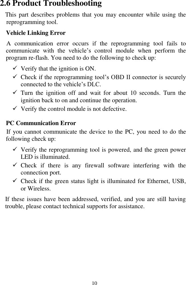
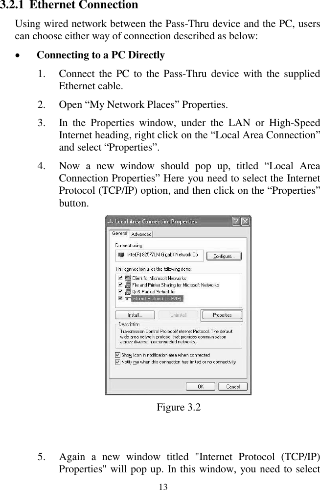
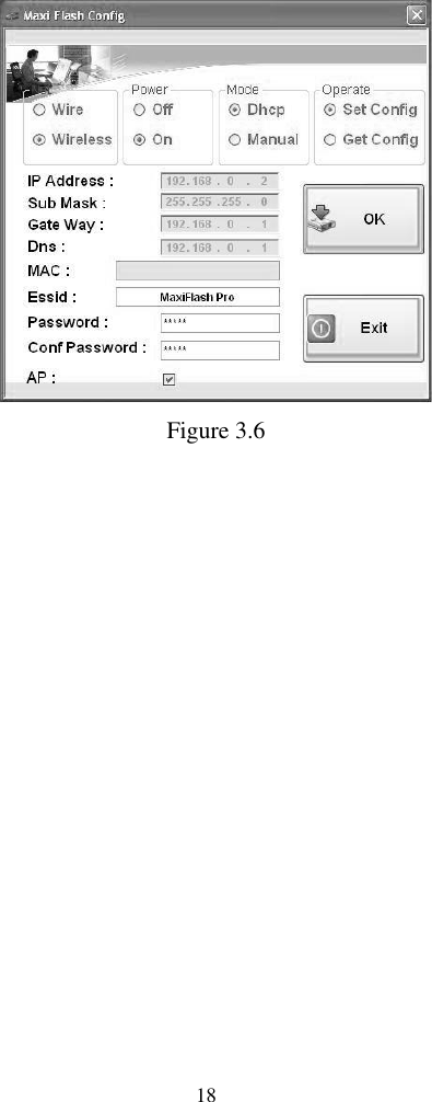
![15 the supplied Ethernet cable. 2) Power up the device by the external power supply; verify the green Power status light on the front panel is on. 3) Verify the Ethernet status lights at the Ethernet port bottom are on. (One illuminates solid orange, the other flashes green light.) 4) Click on ―All Programs‖ from Windows Start Menu, find the ―Maxi Flash‖ entry under ―Autel intelligent tec inc‖, click on ―MaxiFlashCFG‖, and wait for the program interface to pop up. (Figure 3.4) Figure 3.4 [Net: Wire] – Indicates wired network connection between the device and PC. [Net: Wireless] – Indicates wireless network connection between the device and PC. [Power: Off/On] – Turn On/Off the wireless connection (for wireless only). [Mode: DHCP] – Allows automatic network configuring. [Mode: Manual] – Allows manual network configuring.](https://usermanual.wiki/Autel-Intelligent-Tech/2012J2534/User-Guide-1880392-Page-16.png)
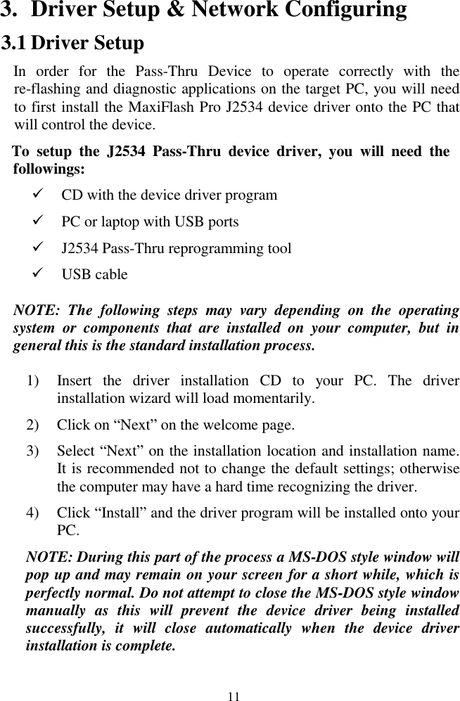
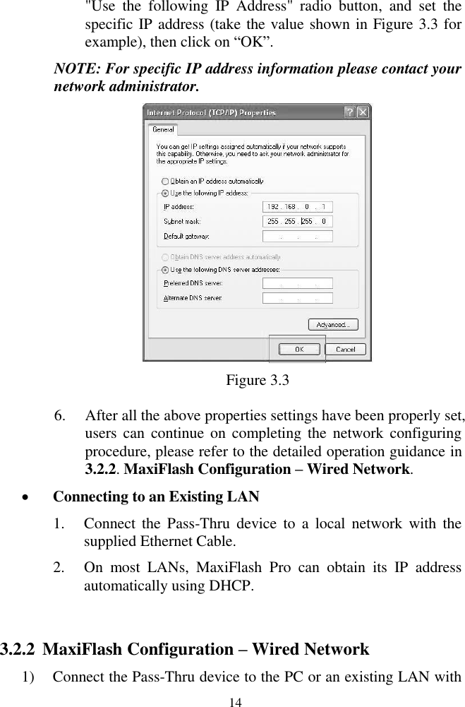
![16 [Operate: Set Config] – Sets the network configuration of the Pass-Thru device. [Operate: Get Config] – Obtains the saved network configuration from the Pass-Thru device. 5) Click on ―Wire‖ in ―Net‖ column. 6) Select ―DHCP‖ in ―Mode‖ column, if you are connecting to the local area network, the MaxiFlash Pro will obtain the IP address automatically. Select ―Manual‖ in ―Mode‖ column, if you are connecting to the PC directly for the first time, and then set the IP address on your own. (Take the value shown in Figure 3.5 for example). 7) Select ―Set Config‖ in ―Operate‖ column to allow setting the network configuration through PC application. 8) Click on ―OK‖ button to save the network configuration. Figure 3.5 3.2.3 MaxiFlash Configuration – Wireless Network 1) Power up the device by the external power supply; verify if the green Power status light at the front panel is on.](https://usermanual.wiki/Autel-Intelligent-Tech/2012J2534/User-Guide-1880392-Page-17.png)