Autel Intelligent Tech 2016-TS408 Professional Scan Tool User Manual Table of Contents
Autel Intelligent Tech. Corp., Ltd. Professional Scan Tool Table of Contents
UserManual.wiki
>
Autel Intelligent Tech
>
2016 TS408 User Manual
User manual
Navigation menu
Upload a User Manual
Namespaces
Wiki Guide
HTML
PDF
Info
Views
User Manual
Discussion / Help
Navigation
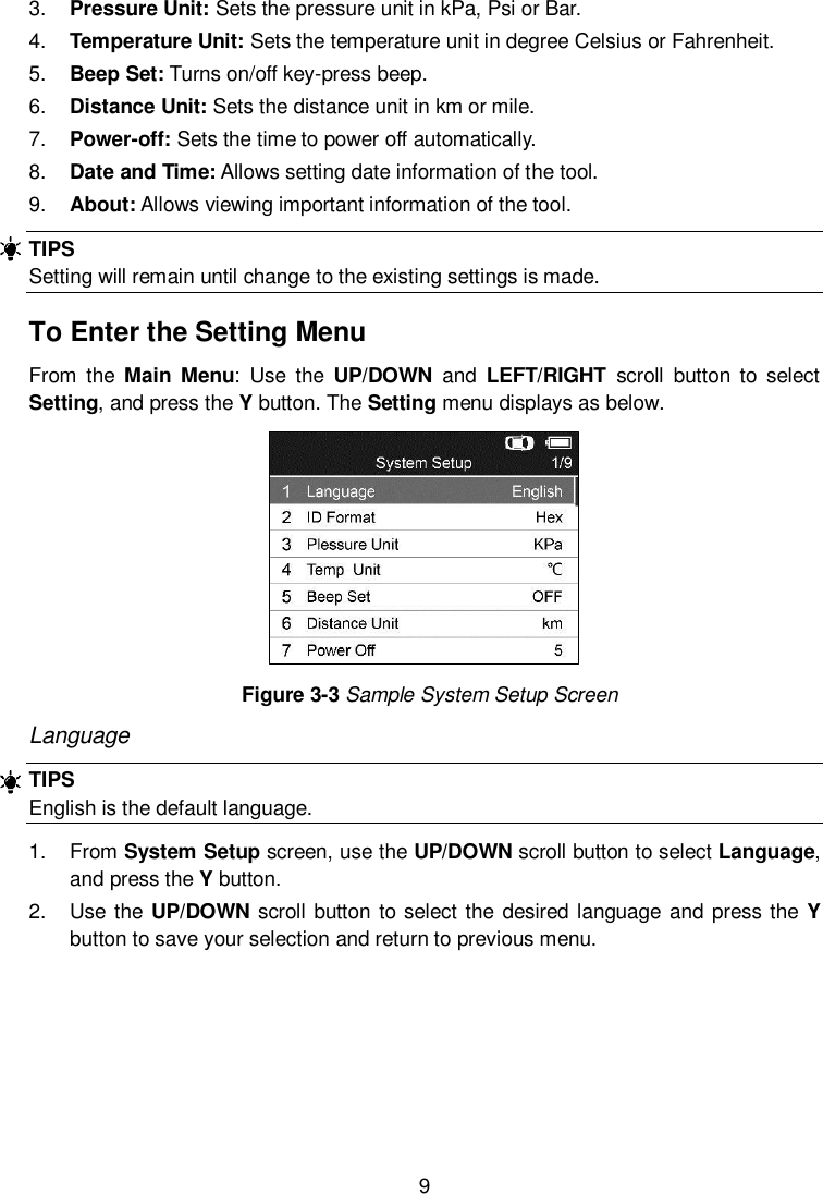
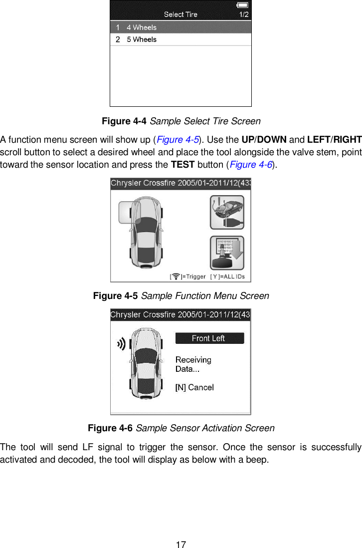
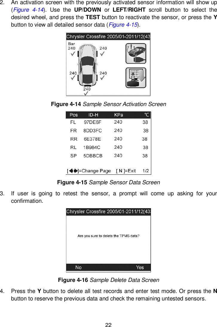
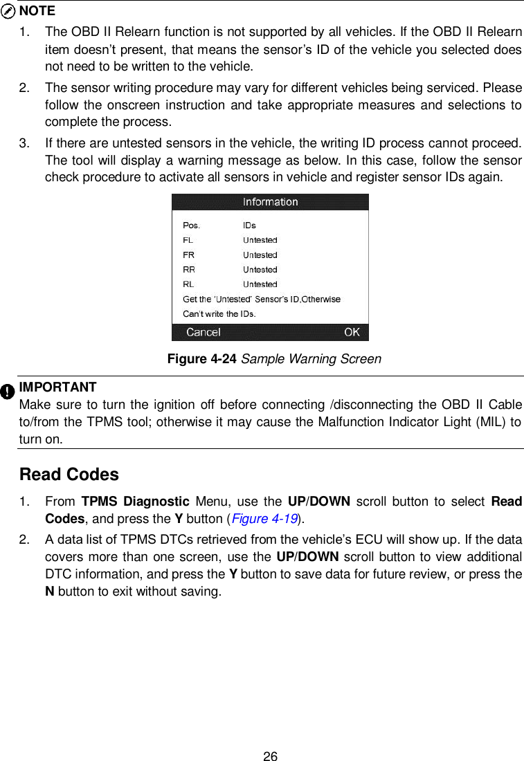
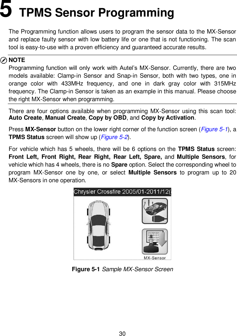
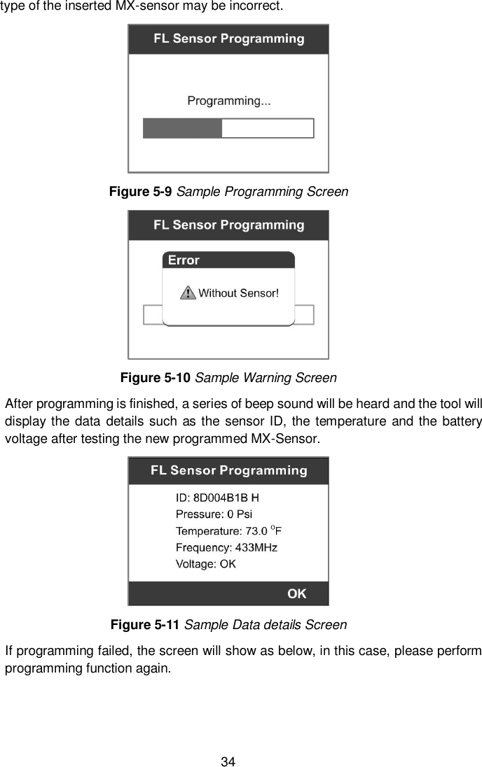
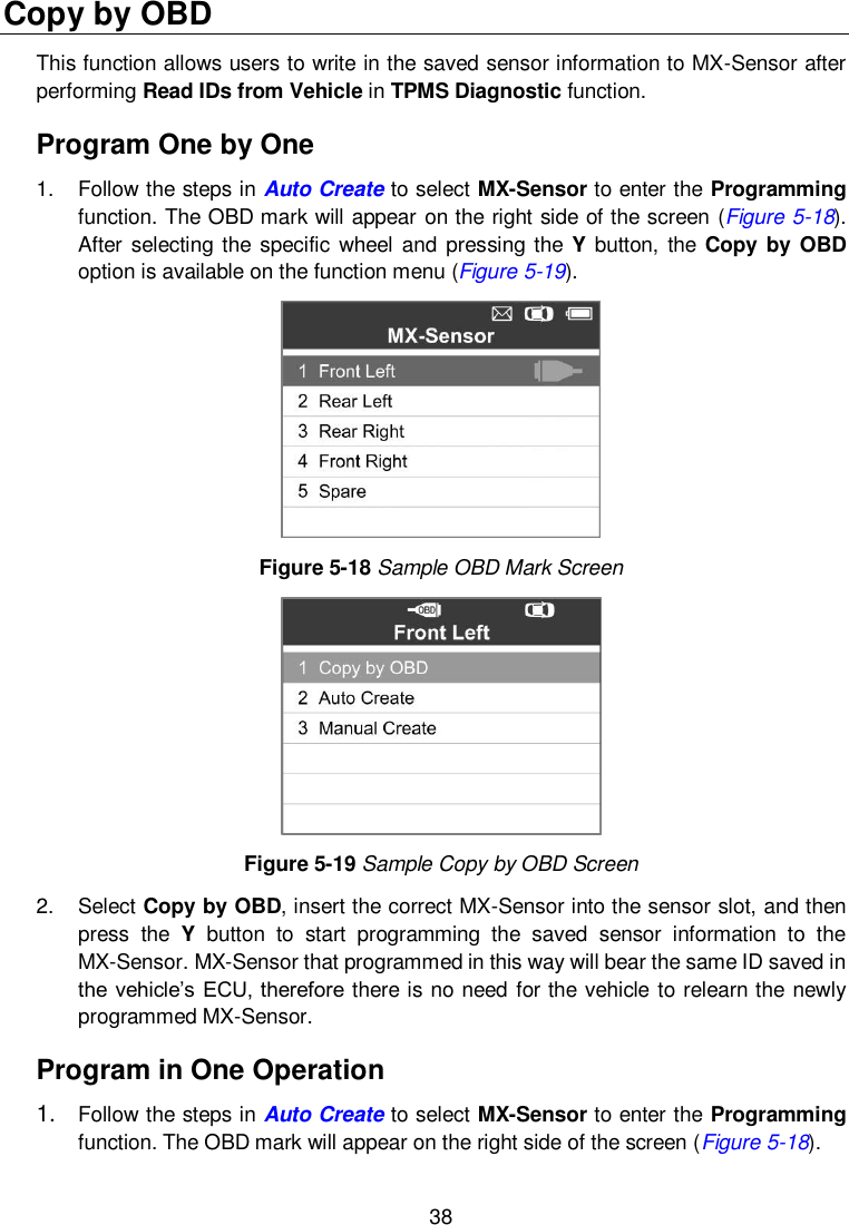
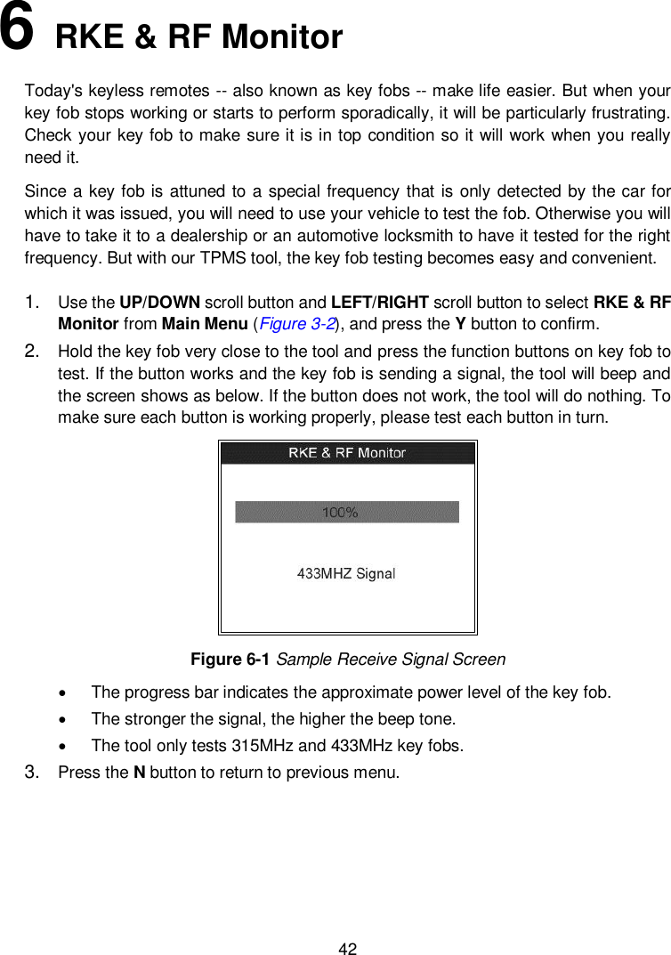
![3 2 General Information TPMS System Review A tire pressure monitoring system (TPMS) is an electronic system designed to monitor the air pressure inside the pneumatic tires on various types of vehicles. TPMS report real-time tire-pressure information to the driver of the vehicle, either via a gauge, a pictogram display, or a simple low-pressure warning light. TPMS can be divided into two different types — direct (dTPMS) and indirect (iTPMS). TPMS are provided both at an OEM (factory) level as well as an aftermarket solution. TPMS Legislation In the United States, the United States Department of Transportation (NHTSA) released the FMVSS No. 138, which requires an installation of a Tire Pressure Monitoring System to all new passenger cars, multipurpose passenger vehicles, trucks, and buses that have a gross vehicle weight rating (GVWR) of 4,536 kg (10,000 lbs.) or less, except those vehicles with dual wheels on an axle, as of 2007. In the European Union, starting November 1, 2012, all new models of passenger cars must be equipped with a TPMS, with even tighter specifications that will be defined by the UNECE Vehicle Regulations (Regulation No. 64). From November 1, 2014, all new passenger cars sold in the European Union must be equipped with TPMS. On July 13, 2010, the South Korean Ministry of Land, Transport and Maritime Affairs announced a pending partial-revision to the Korea Motor Vehicle Safety Standards (KMVSS), specifying that "TPMS shall be installed to passenger vehicles and vehicles of GVW 3.5 tons or less, ... [effective] on January 1, 2013 for new models and on June 30, 2014 for existing models". Japan is expected to adopt European Union legislation approximately one year after European Union implementation. Further countries to make TPMS mandatory include Russia, Indonesia, the Philippines, Israel, Malaysia and Turkey. TPMS Tell-tale Light When diagnosing TPMS systems, you should understand what the TPMS tell-tale light means. When turning the ignition OFF to ON, the TPMS tell-tale should come on, and then go off, which indicates the system is working fine. If the light stays on, there would be a pressure problem. If the light flashes, there would be a system problem, which can range from faulty sensors to sensors on the vehicle that haven’t been learned to that vehicle.](https://usermanual.wiki/Autel-Intelligent-Tech/2016-TS408/User-Guide-3234308-Page-8.png)

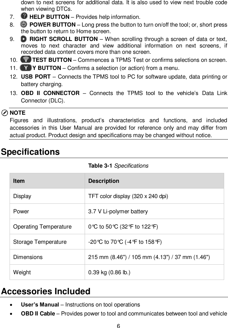
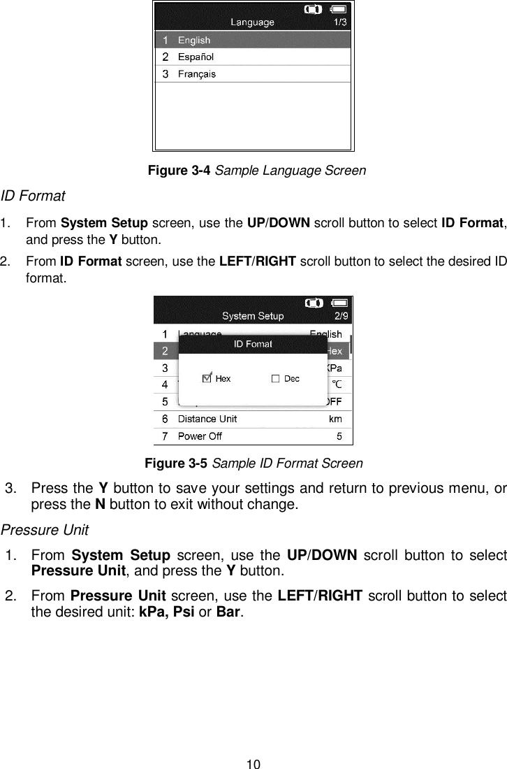
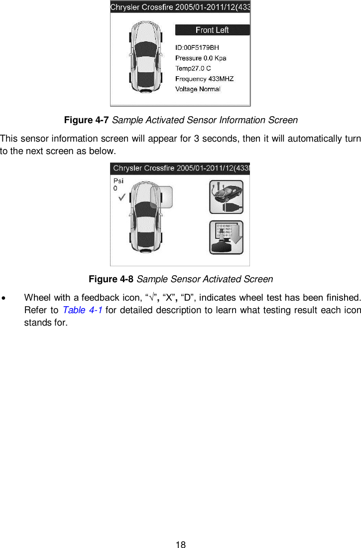
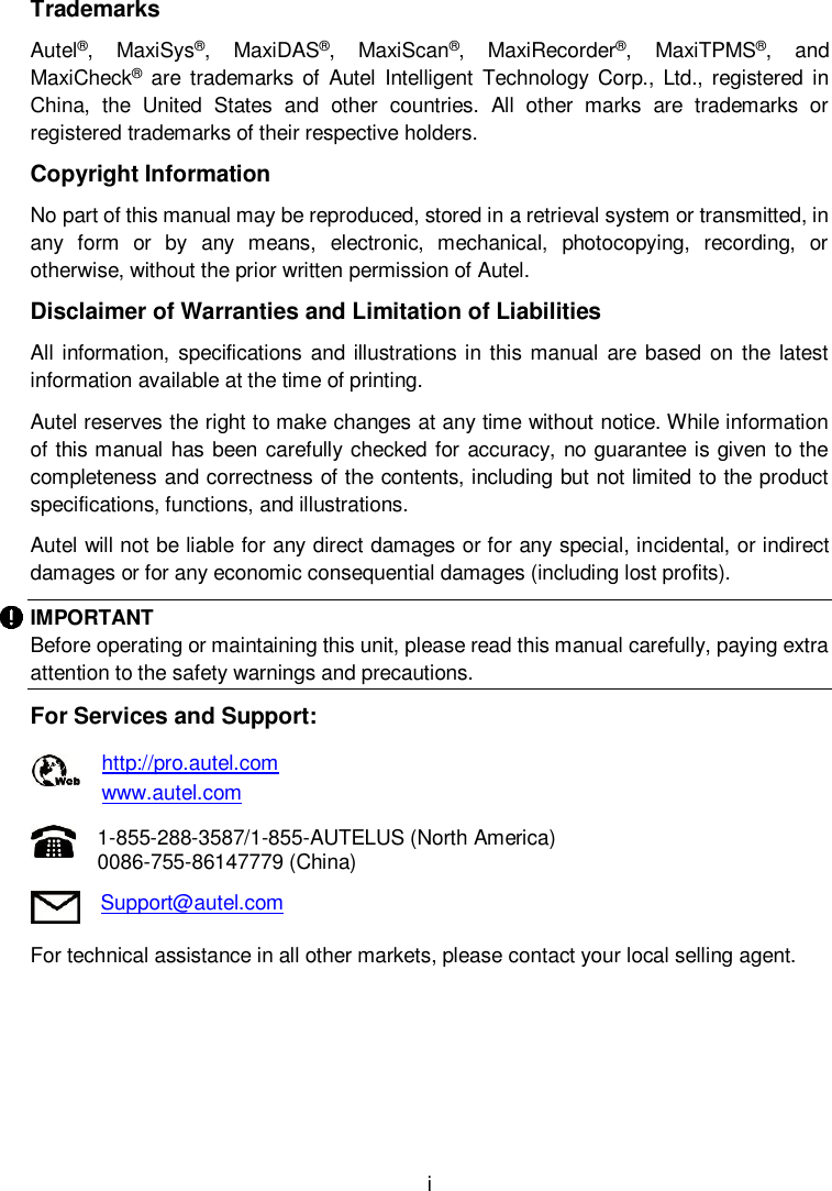
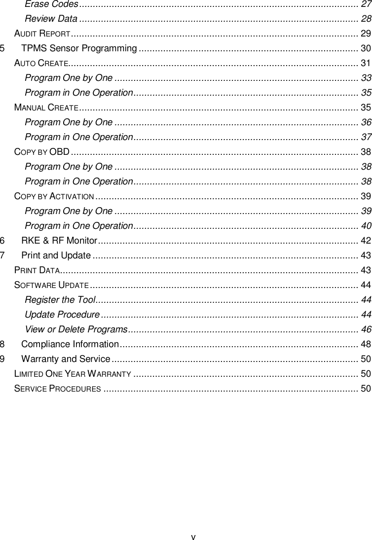
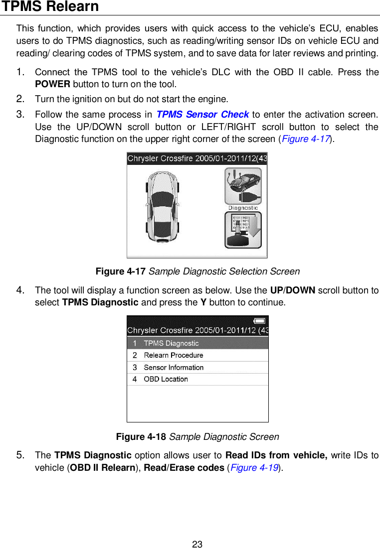
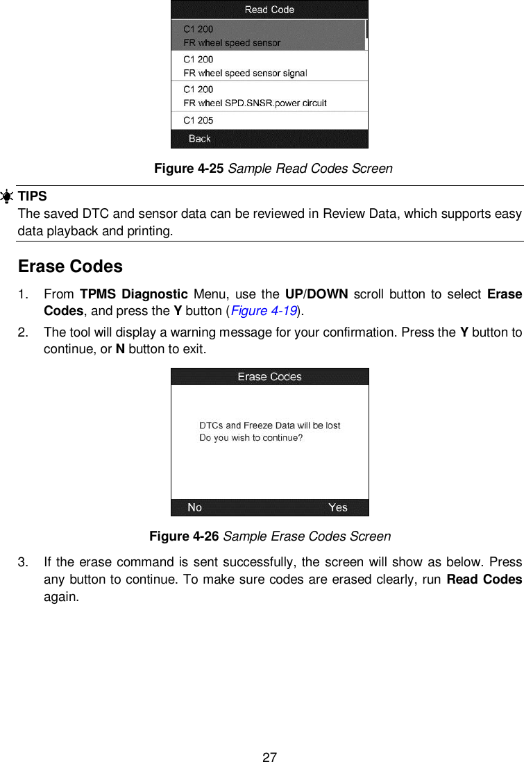
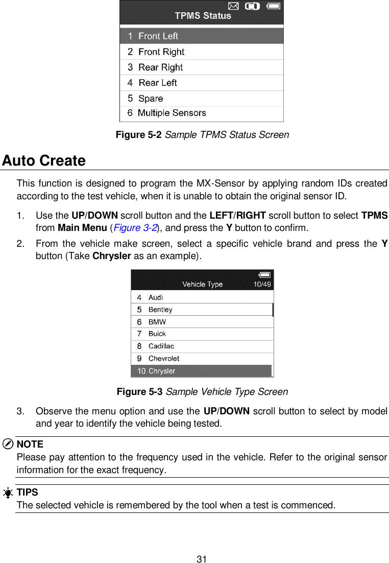
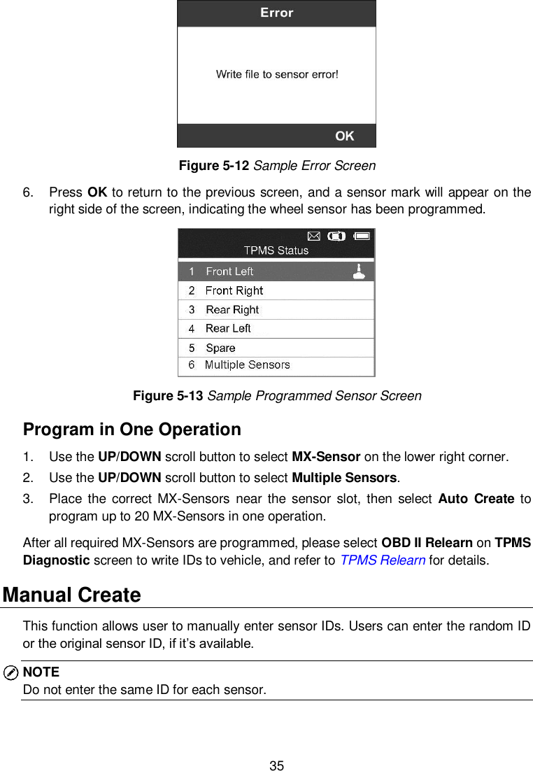
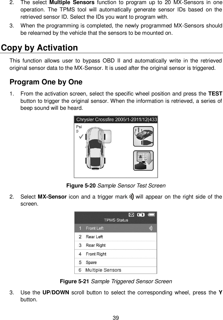
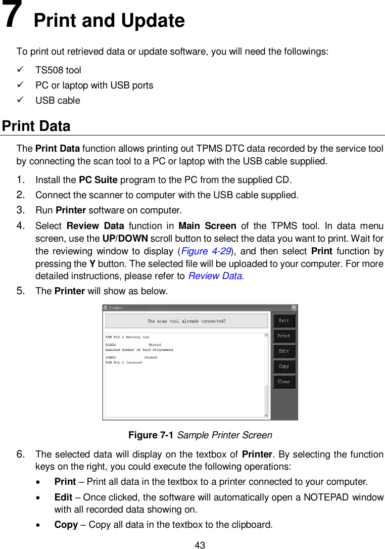
![21 Figure 4-12 Sample Tested Sensor Information Screen-1 Figure 4-13 Sample Tested Sensor Information Screen-2 [Pos] – Indicates the wheel sensor position. [ID-H/D] – Shows sensor ID data. [kPa/Psi/Bar] – Indicates tire pressure. [°C /°F ] – Indicates tire temperature. [BAT] – Indicates battery condition. [Mode] – Defines tire sensor working mode or status. [Modulation] – Indicates sensor signal amplitude. NOTE Different ID format, pressure and temperature units will display at the title bar according to the device’s system setting, please refer to System Setting for detailed instruction. Select by Latest Test This function allows you to review the last tested sensor data and activate the sensor by using the wave signal of the latest trigger event, which is very convenient and useful for technicians to wake up sensors of the same vehicle. 1. Use the UP/DOWN scroll button and LEFT/RIGHT scroll button to select Latest Test from Main Menu (Figure 3-2).](https://usermanual.wiki/Autel-Intelligent-Tech/2016-TS408/User-Guide-3234308-Page-26.png)
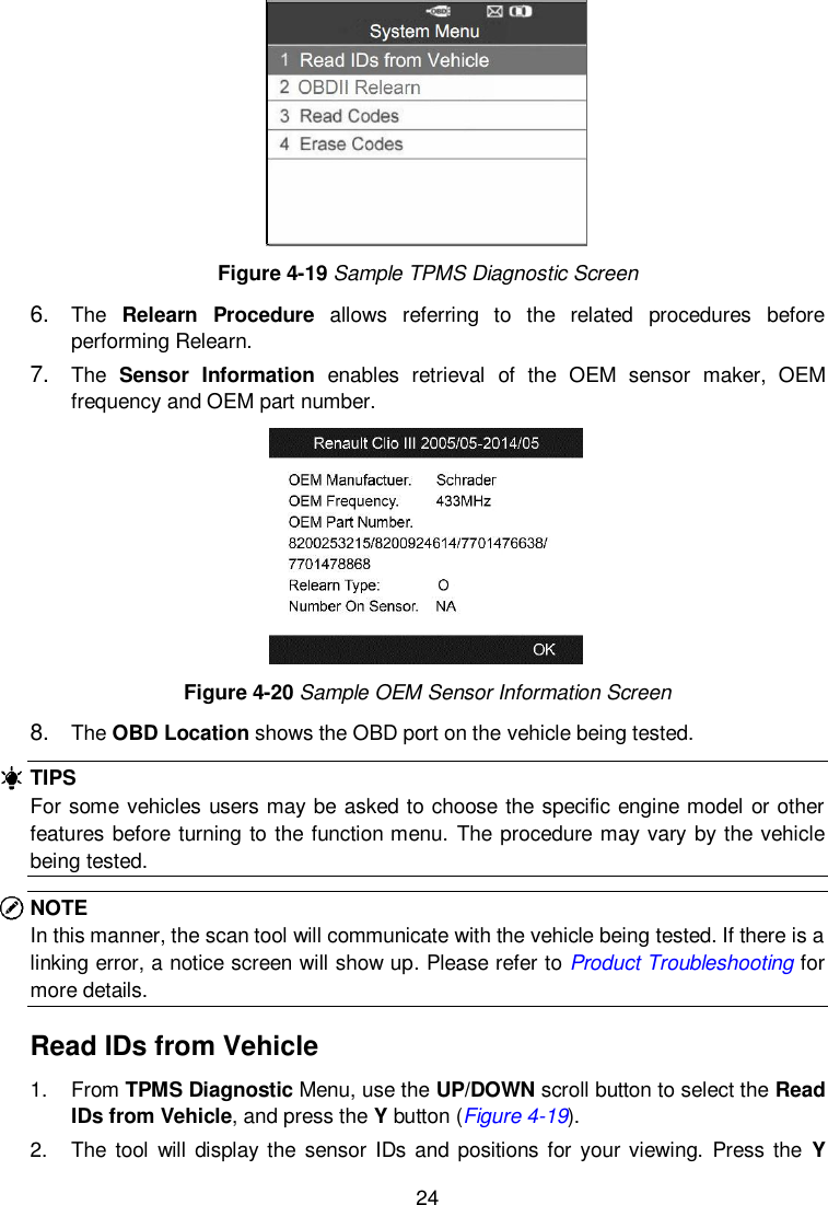
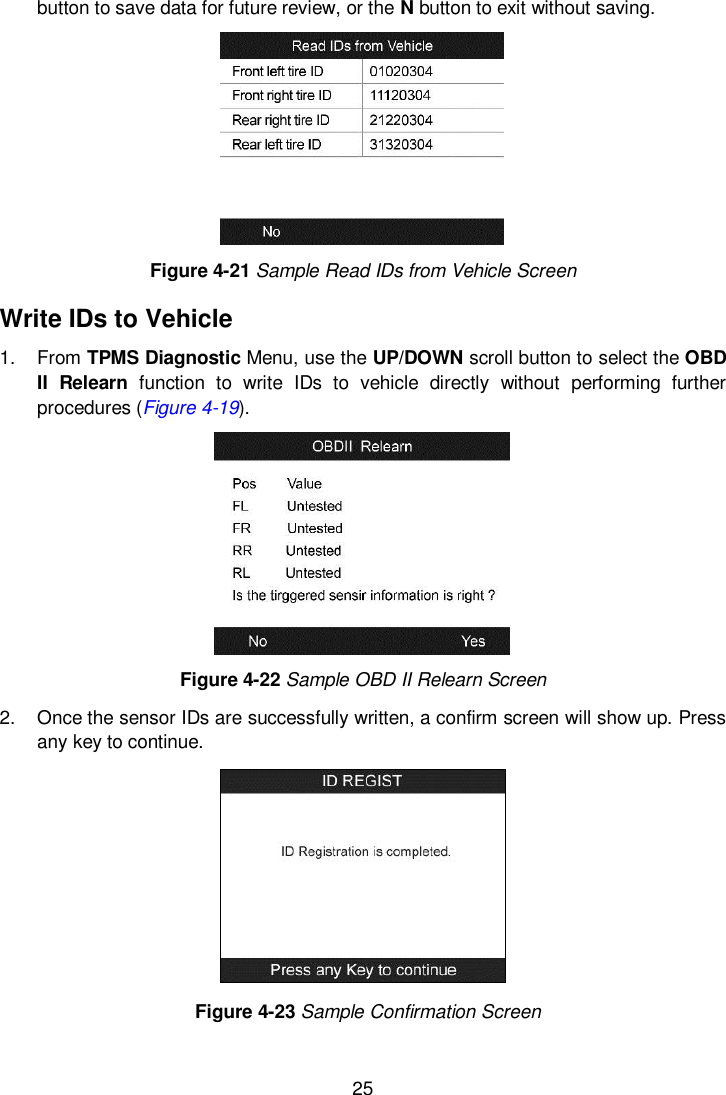
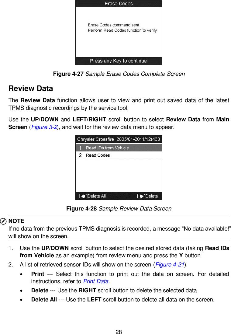
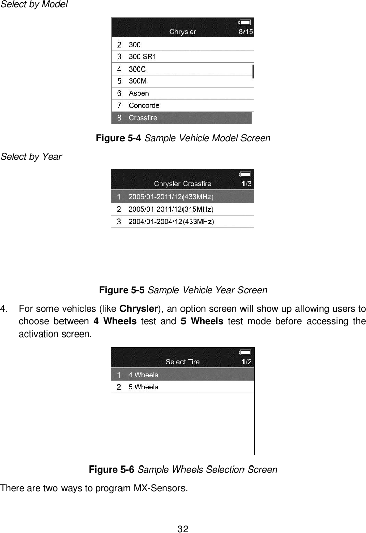
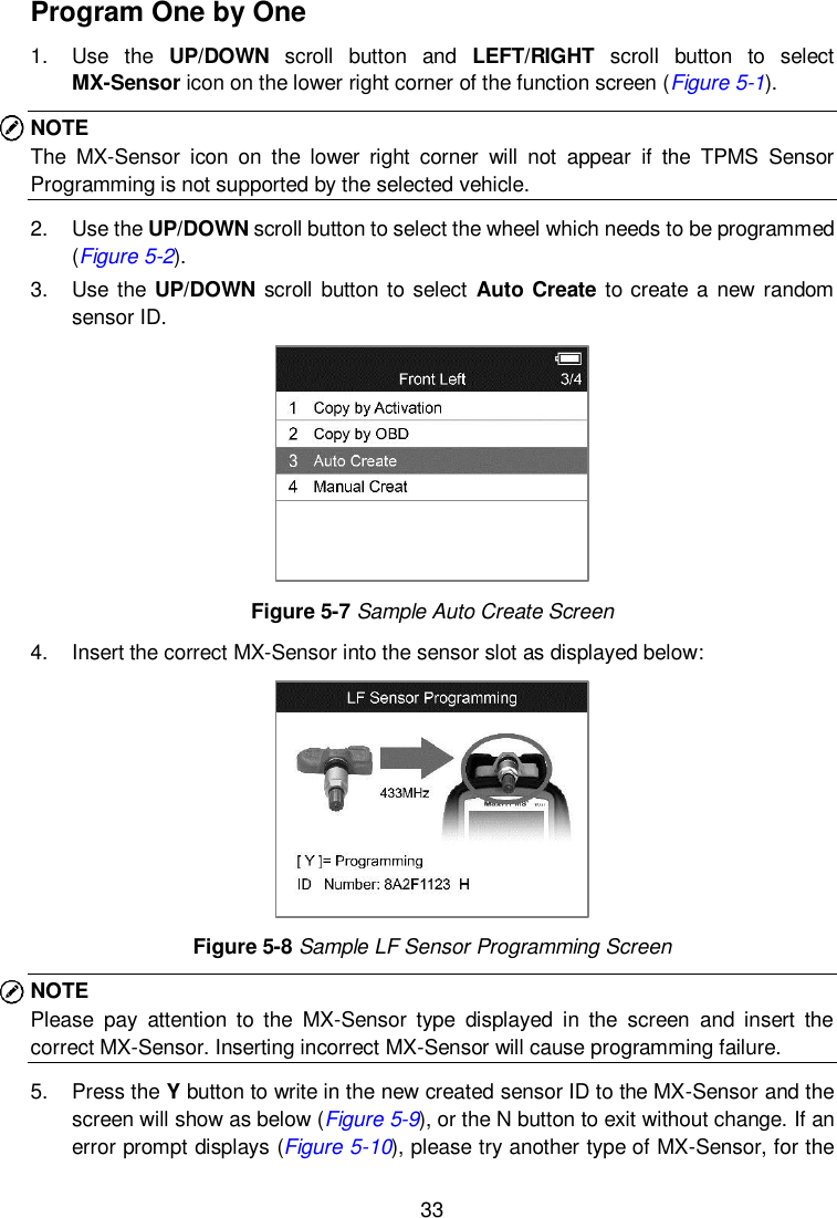
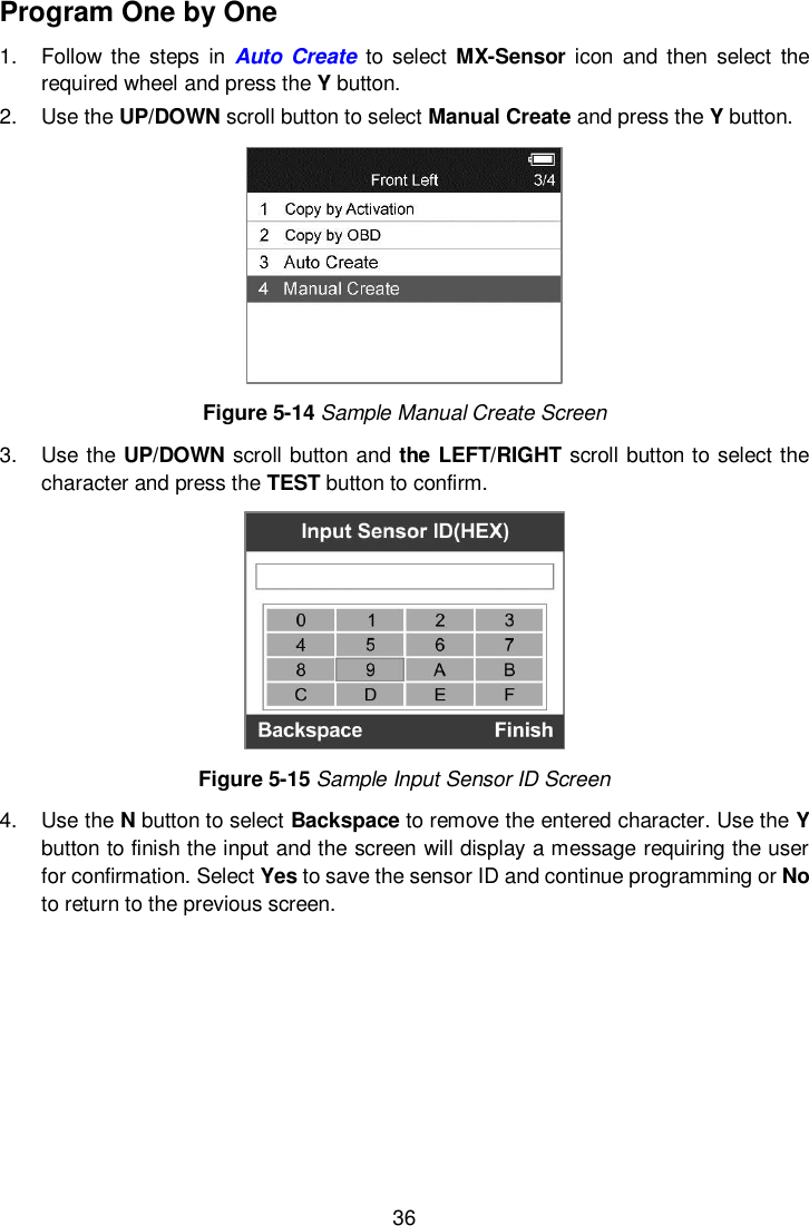
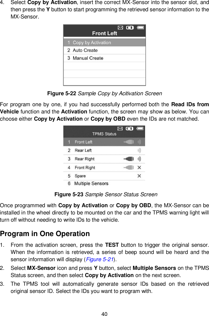
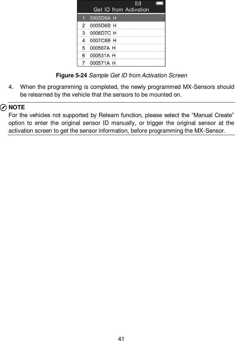
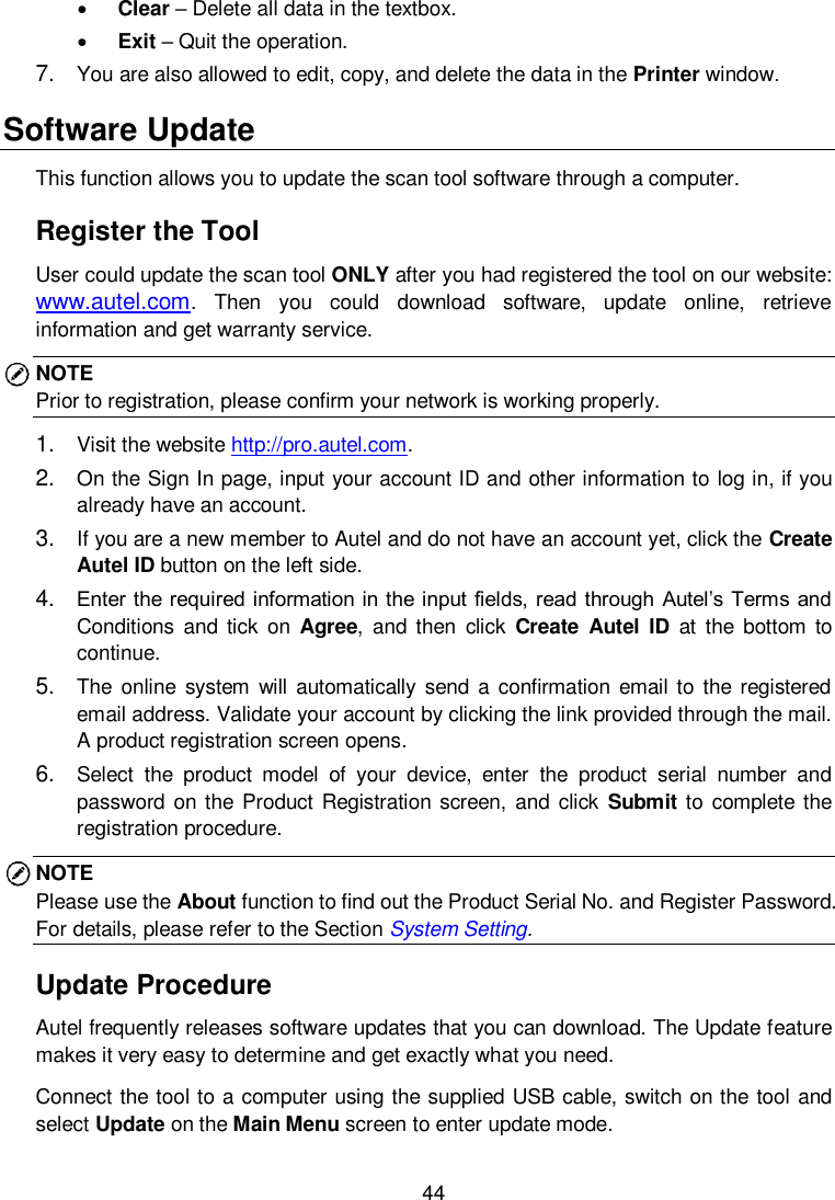
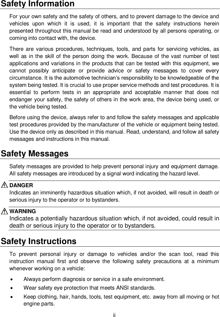
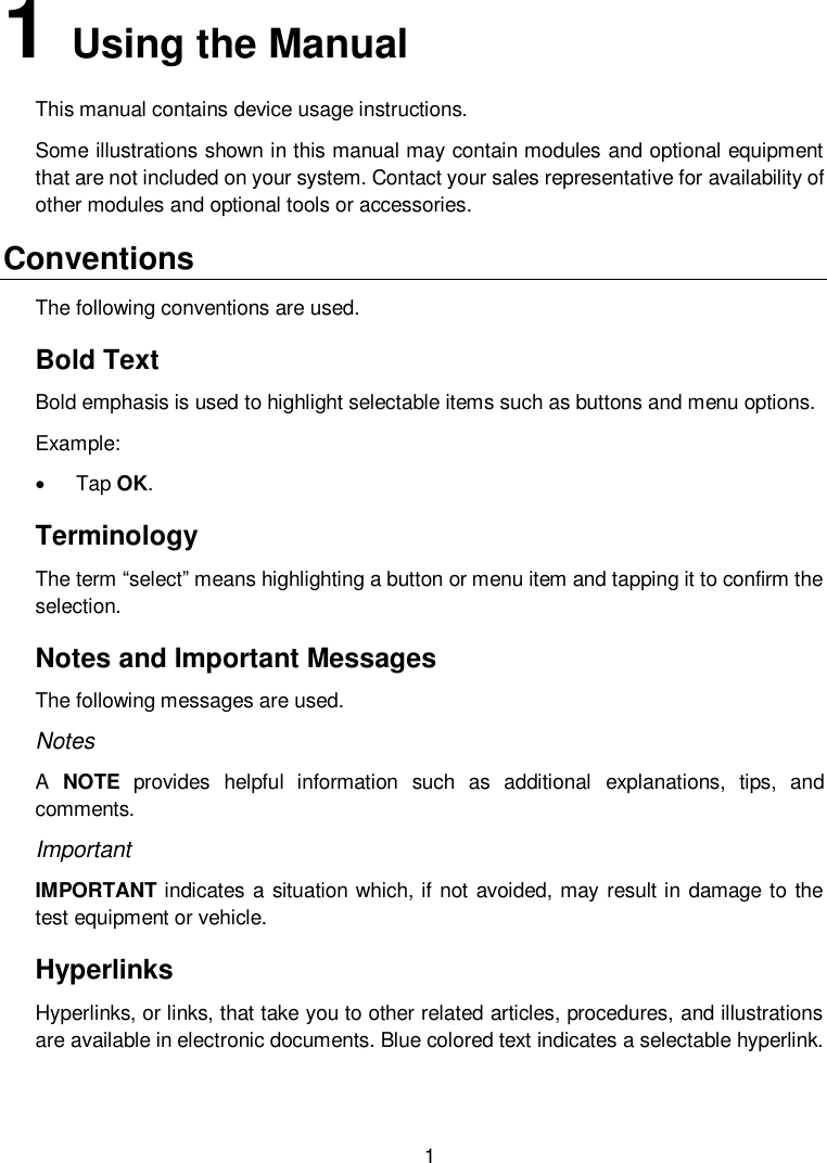
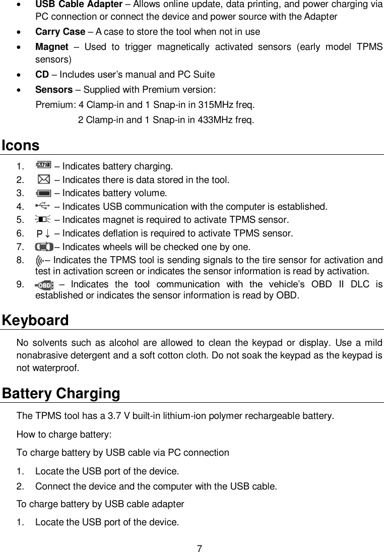
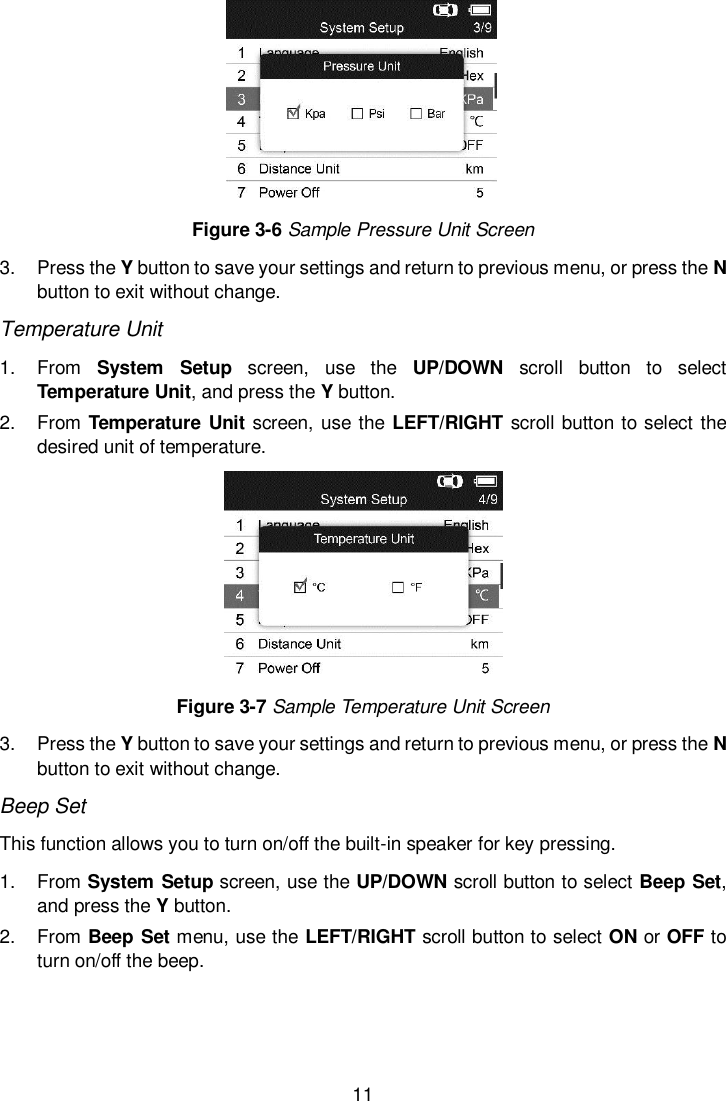
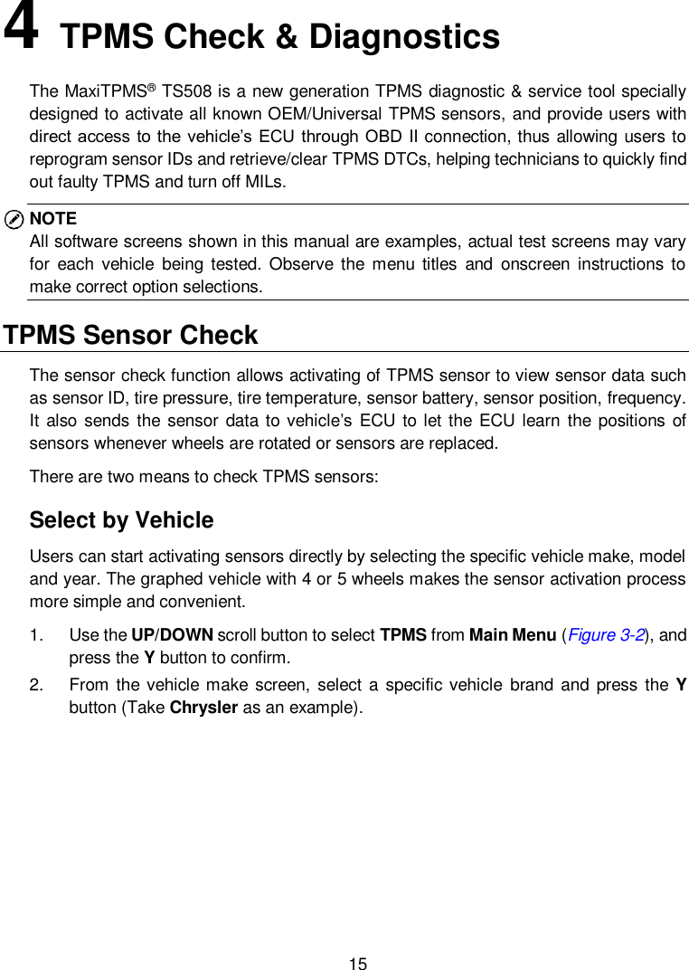
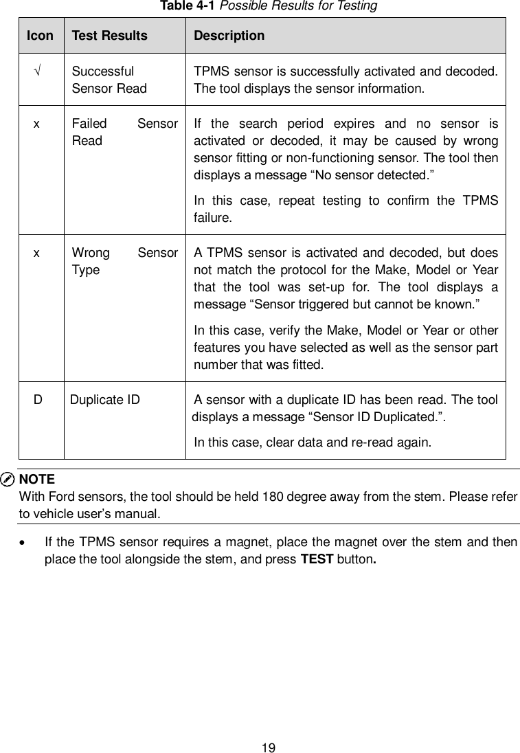
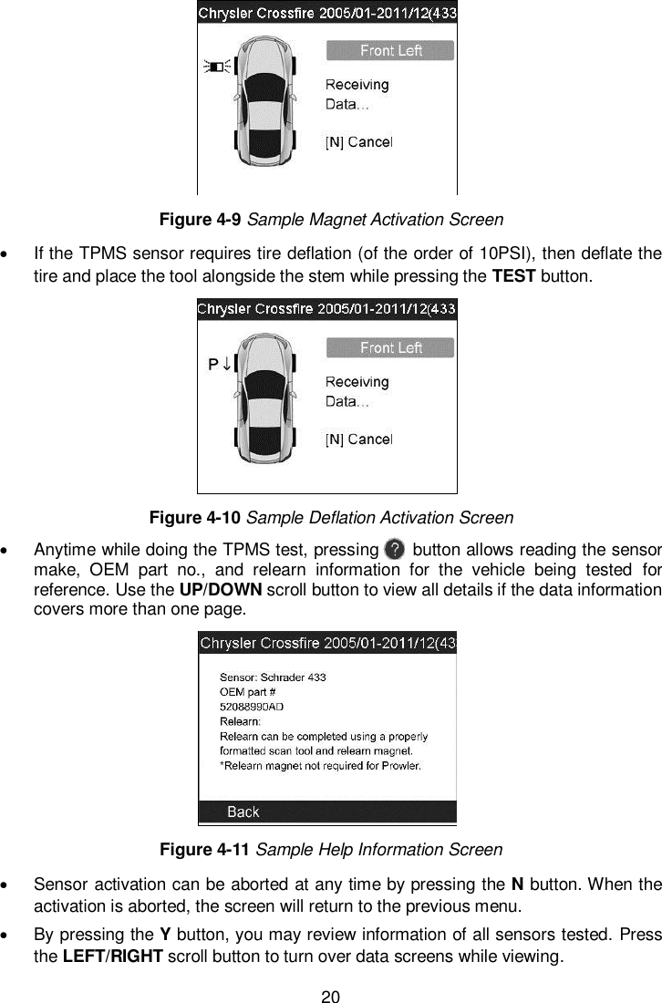
![45 Follow the update procedure to finish updating. 1. Run Autel Update in the PC Suite program. Wait for the Log In window to pop up. Figure 7-2 Sample Log In Window 2. Enter your Autel ID and password and wait for the Update window to display. If you forget your password unintentionally, you may always click the [Forget Password?] to link to our website and get your password back. 3. In the Update window, select the items you want to install. Usually, you should install all available updates. Figure 7-3 Sample Update Window Generally there are two ways to update the programs: Batch Update 1. Select the programs that you would update by clicking on the check boxes next to those items. Then click the Update Selected Items button on the right side of screen. Or 2. Click on the Select All checkbox on the right side of screen and all updatable items will be selected automatically. Then click the Update Selected Items button on the right side of screen. 3. Check the updating process by observing the upper left progress bar [Downloads] and upper right progress bar [Installs]. You may also find progress information in](https://usermanual.wiki/Autel-Intelligent-Tech/2016-TS408/User-Guide-3234308-Page-50.png)
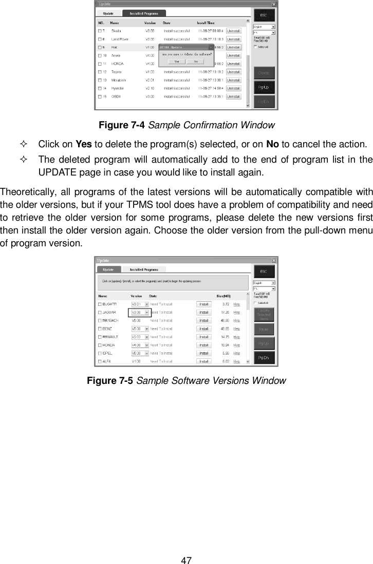
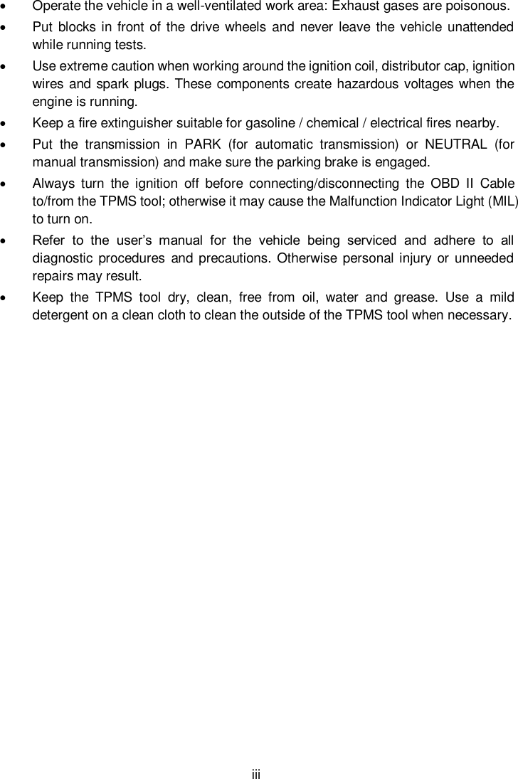
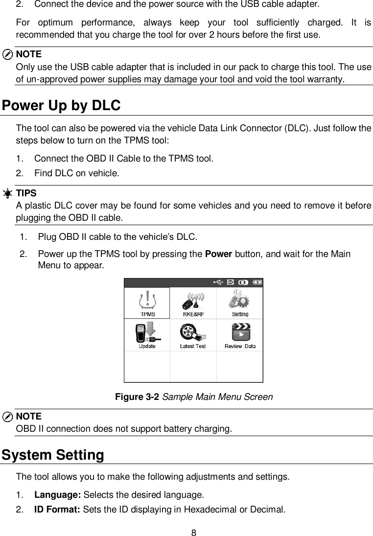
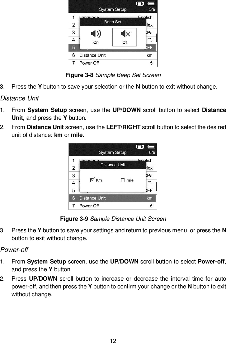
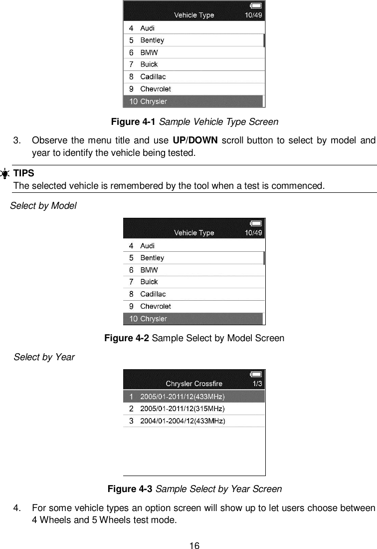
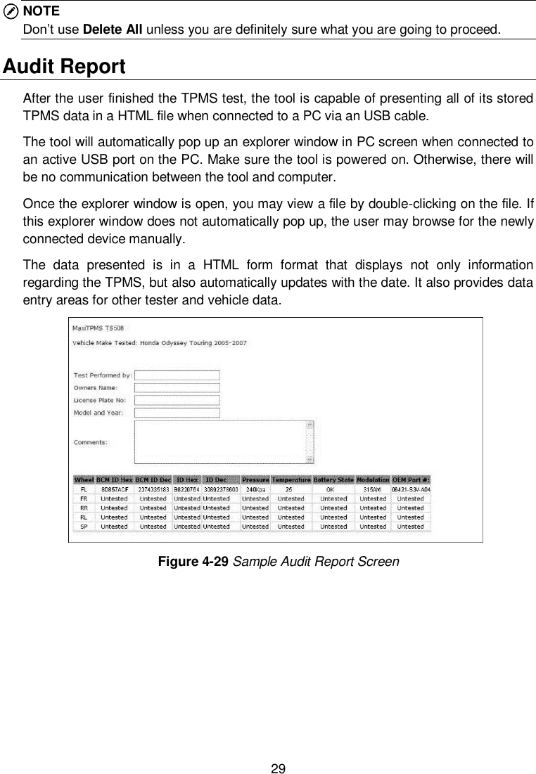
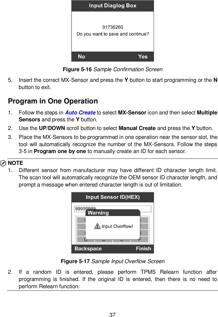
![46 the Status column of updated items. 4. Anytime you could click the Pause button on the right side of screen to suspend all progresses, and the state of those suspended items would change to STOPPED. 5. To resume updating process, you may need to select those suspended items again, and then click the Update Selected Items button. The progress will resume from the break point. 6. When the downloading is completed, the downloaded programs will be installed automatically. The new version will replace the old version. Single Update 1. Find out the desired updating item and click the Install button in the same line and the Install button changes to Pause at the same time. 2. Check the updating process by observing the upper left progress bar [Downloads] and upper right progress bar [Installs]. You may also find progress information in the Status column of updated items. 3. Anytime you could click the Pause button in the line to suspend this progress, and the state of this item would change to STOPPED. 4. To resume updating process, click the Install button in the line again. The progress will resume from the break point. 5. When the downloading is completed, the downloaded program will be installed automatically. The new version will replace the old one. 6. Once the update is complete, disconnect the tool from the computer. It is now updated and ready to go. View or Delete Programs To view the list of installed programs or to delete an installed program, please follow these steps: 1. Click on the Installed Programs tag entry and the page will show the list of programs installed. 2. Select the program(s) that you would delete. Batch delete: Select the programs that you would delete by clicking on the check boxes to the left of those items. Then click the Delete button on the right side of screen. Single delete: Click the Uninstall button in the line of your would-be-deleted program. 3. A window asking “Are you sure to delete the software?” will pop up for your confirmation.](https://usermanual.wiki/Autel-Intelligent-Tech/2016-TS408/User-Guide-3234308-Page-51.png)