Autel Intelligent Tech 2018-TS201 Professional Scan Tool User Manual Table of Contents
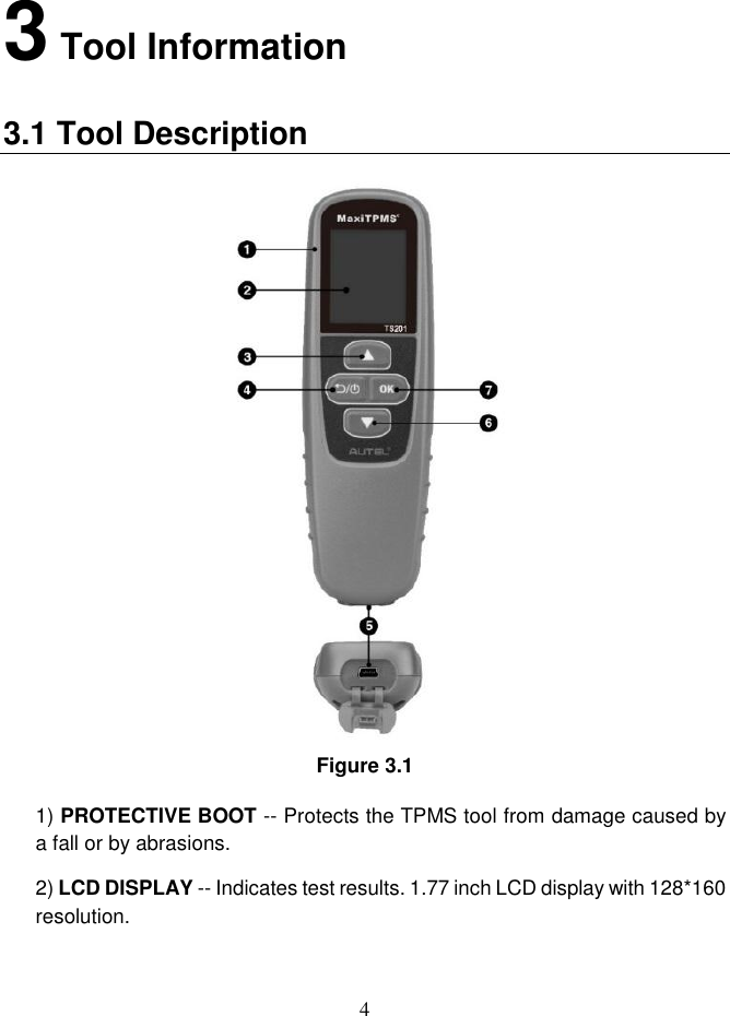
Autel Intelligent Tech. Corp., Ltd. Professional Scan Tool Table of Contents
UserManual.wiki
>
Autel Intelligent Tech
>
2018 TS201 User Manual
User Manual
Navigation menu
Upload a User Manual
Namespaces
Wiki Guide
HTML
PDF
Info
Views
User Manual
Discussion / Help
Navigation
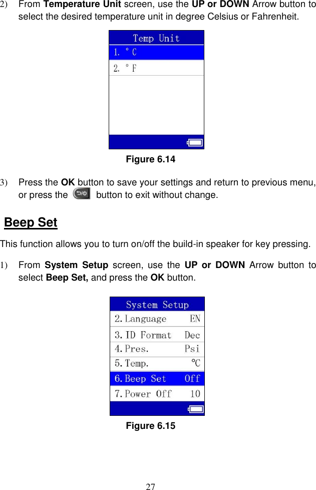
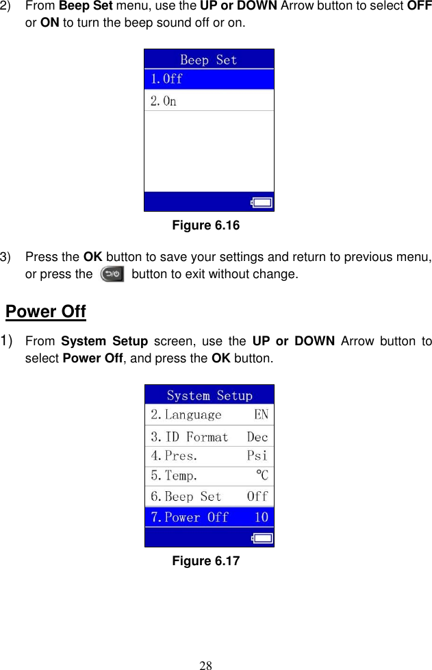
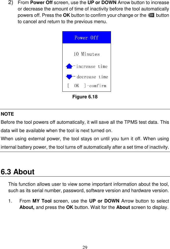
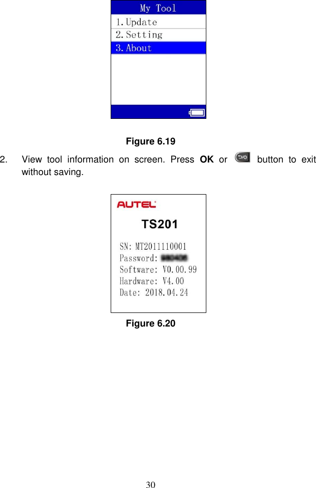
![2 2 General Information 2.1 TPMS system review A tire pressure monitoring system (TPMS) is an electronic system designed to monitor the air pressure inside the pneumatic tires on various types of vehicles. TPMS report real-time tire-pressure information to the driver of the vehicle, either via a gauge, a pictogram display, or a simple low-pressure warning light. TPMS can be divided into two different types - direct (dTPMS) and indirect (iTPMS). TPMS are provided both at an OEM (factory) level as well as an aftermarket solution. 2.2 TPMS Legislation In the United States, the United States Department of Transportation (NHTSA) released the FMVSS No. 138, which requires an installation of a Tire Pressure Monitoring System to all new passenger cars, multipurpose passenger vehicles, trucks, and buses that have a gross vehicle weight rating (GVWR) of 4,536 kg (10,000 lbs.) or less, except those vehicles with dual wheels on an axle, as of 2007. In the European Union, starting November 1, 2012, all new models of passenger cars must be equipped with a TPMS, with even tighter specifications that will be defined by the UNECE Vehicle Regulations (Regulation No. 64). From November 1, 2014, all new passenger cars sold in the European Union must be equipped with TPMS. On July 13, 2010, the South Korean Ministry of Land, Transport and Maritime Affairs announced a pending partial-revision to the Korea Motor Vehicle Safety Standards (KMVSS), specifying that "TPMS shall be installed to passenger vehicles and vehicles of GVW 3.5 tons or less, ... [effective] on January 1, 2013 for new models and on June 30, 2014 for existing models". Japan is expected to adopt European Union legislation approximately one year after European Union implementation. Further countries to make TPMS mandatory include Russia, Indonesia, the Philippines, Israel, Malaysia and Turkey.](https://usermanual.wiki/Autel-Intelligent-Tech/2018-TS201/User-Guide-4104606-Page-4.png)