Autel Intelligent Tech 3017501601 TPMS diagnostic and service tool User Manual Table of Contents
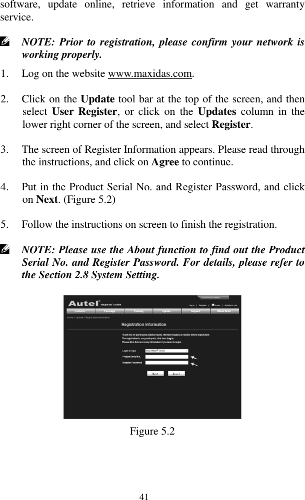
Autel Intelligent Tech. Corp., Ltd. TPMS diagnostic and service tool Table of Contents
UserManual.wiki
>
Autel Intelligent Tech
>
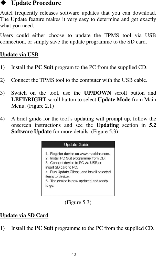
3017501601 User Manual
User manual
Navigation menu
Upload a User Manual
Namespaces
Wiki Guide
HTML
PDF
Info
Views
User Manual
Discussion / Help
Navigation
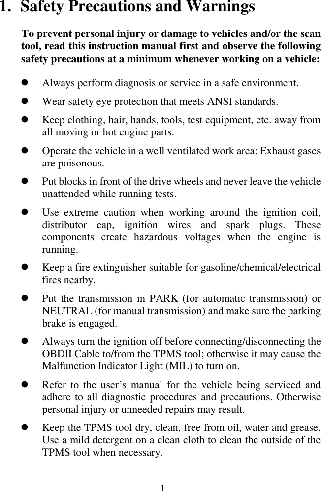
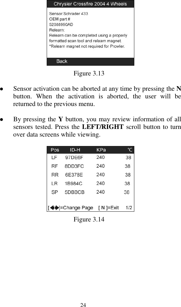
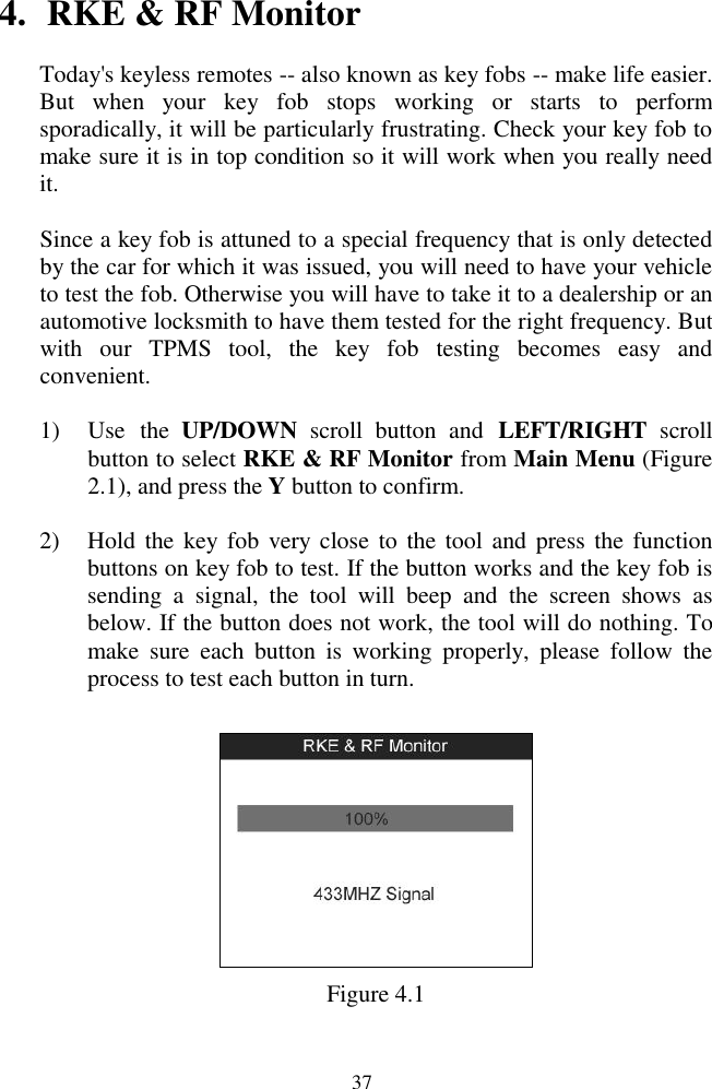
![25 Figure 3.15 [Pos] – Indicates the wheel sensor position. [ID-H/D] – Shows sensor ID data. [KPa/Psi/Bar] – Indicates wheel pressure. [℃/℉] – Indicates wheel temperature. [BAT] – Indicates battery condition. [Mode] – Defines tire sensor working mode or status. [Modulation] – Indicates sensor signal frequency. NOTE: Different ID format, pressure and temperature units will display at the title bar according to the device’s system setting, please refer to 2.8 System Setting for detailed guidance. B. Latest Test This function allows you to review the last tested sensor data and activate the sensor by using the wave signal of the latest trigger event, which is very useful for technicians to wake up sensors of the same vehicle. 1) Use the UP/DOWN scroll button and LEFT/RIGHT scroll button to select Latest Test from Main Menu (Figure 2.1). 2) A function menu screen with the previously activated sensor information will show up (Figure 3.16), use the UP/DOWN or LEFT/RIGHT scroll button to select a scanned wheel, and then](https://usermanual.wiki/Autel-Intelligent-Tech/3017501601/User-Guide-1874524-Page-26.png)
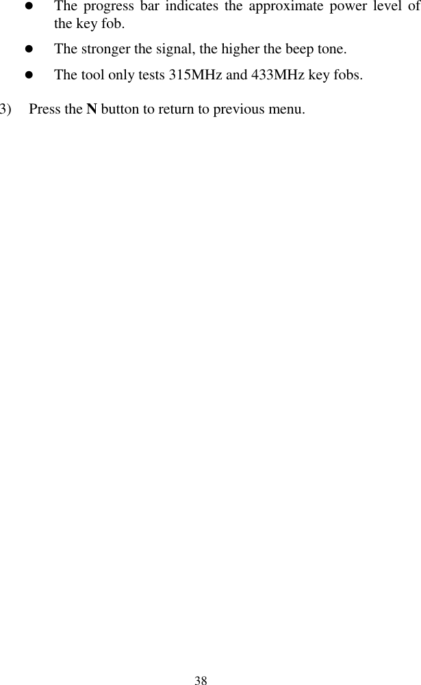
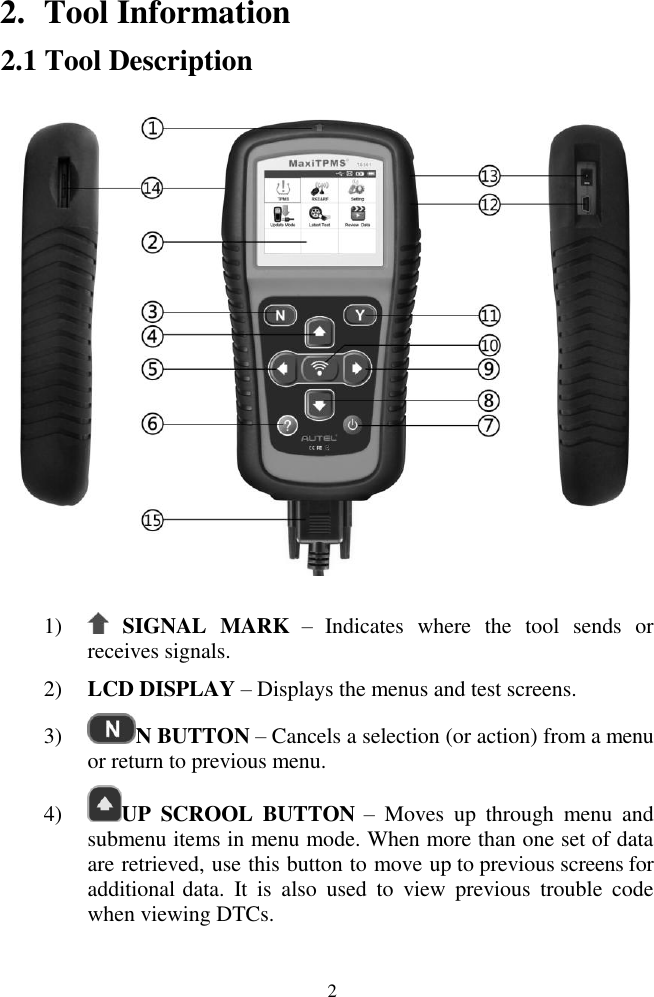
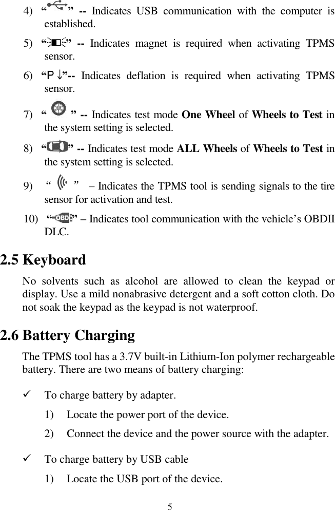
![43 2) Switch off the TPMS tool and remove the SD card from the card slot. 3) Connect the SD card to your PC, and follow the procedure below to finish the update procedure. Updating 1) Run Update Client in the PC Suit programme. Wait for the Log In window to pop up. (Figure 5.4) Figure 5.4 2) Put in the user name and password and wait for the Update window to display. If you forget your password unintentionally, you may always click the [Forget your password?] to link to our website and find your password back. 3) In the Update window, select the items you want to install. Usually, you should install all available updates.](https://usermanual.wiki/Autel-Intelligent-Tech/3017501601/User-Guide-1874524-Page-44.png)
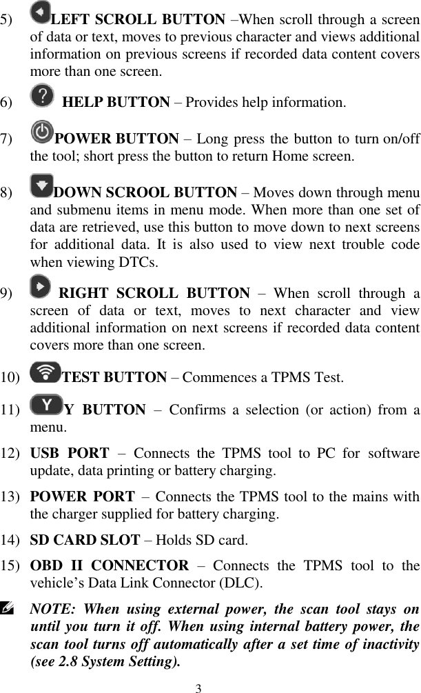
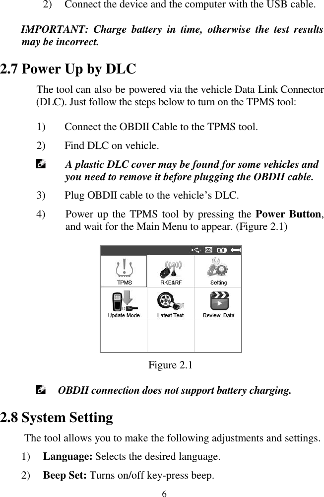
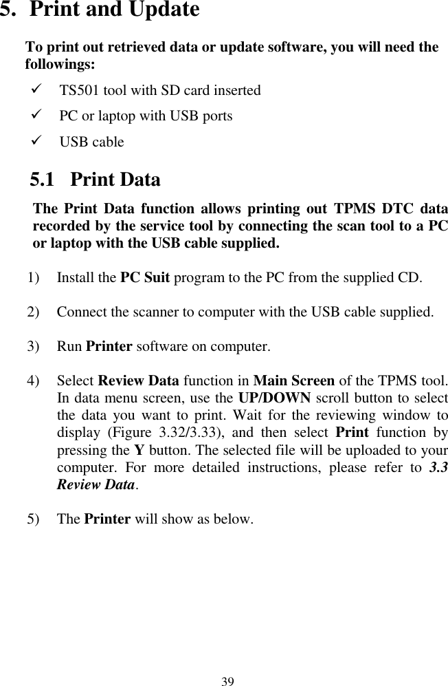
![44 Figure 5.5 Generally there are two ways to update the programs: Batch updating Select the programs that you would update by clicking on the check boxes next to those items. Then click the Update Selected Items button on the right side of screen. Or click on the SELECT ALL checkbox on the right side of screen and all updatable items will be selected automatically. Then click the Update Selected Items button on the right side of screen. Check the updating process by observing the upper left progress bar [downloading] and upper right progress bar [installing]. You may also find progress information in the Status column of updated items. Anytime you could click the Pause button on the right side of screen to suspend all progresses, and the state of those suspended items would change to STOPPED. To resume updating process, you may need to select those suspended items again, and then click the Update Selected Items button. The progress will resume from the break point. When the downloading is completed, the downloaded programs will be installed automatically. The new version will replace the old version.](https://usermanual.wiki/Autel-Intelligent-Tech/3017501601/User-Guide-1874524-Page-45.png)
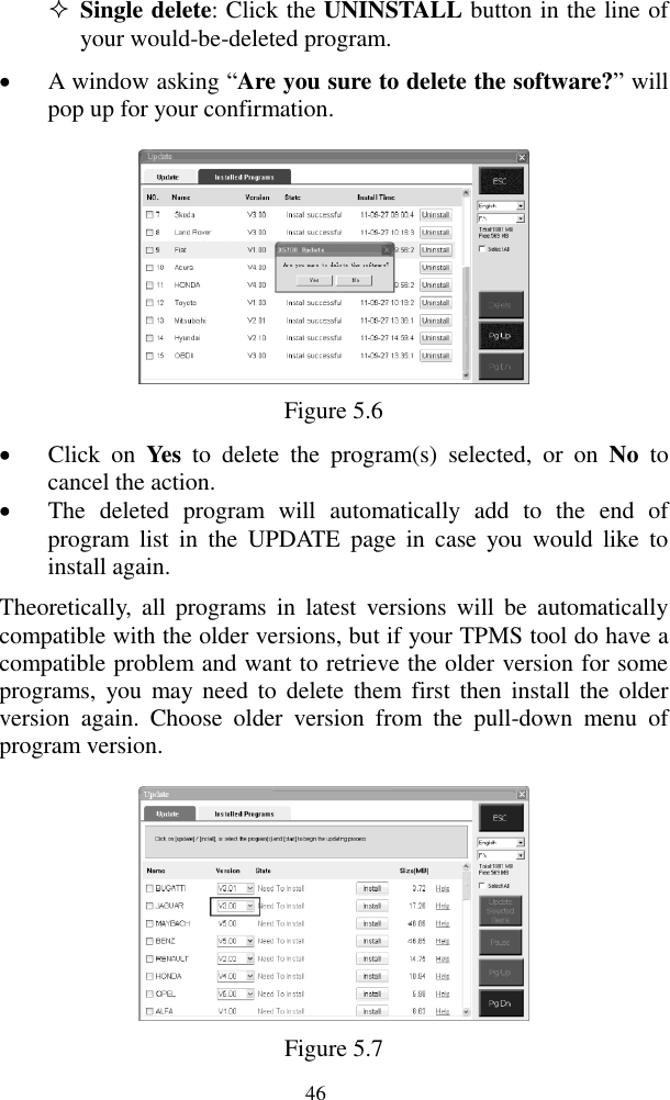
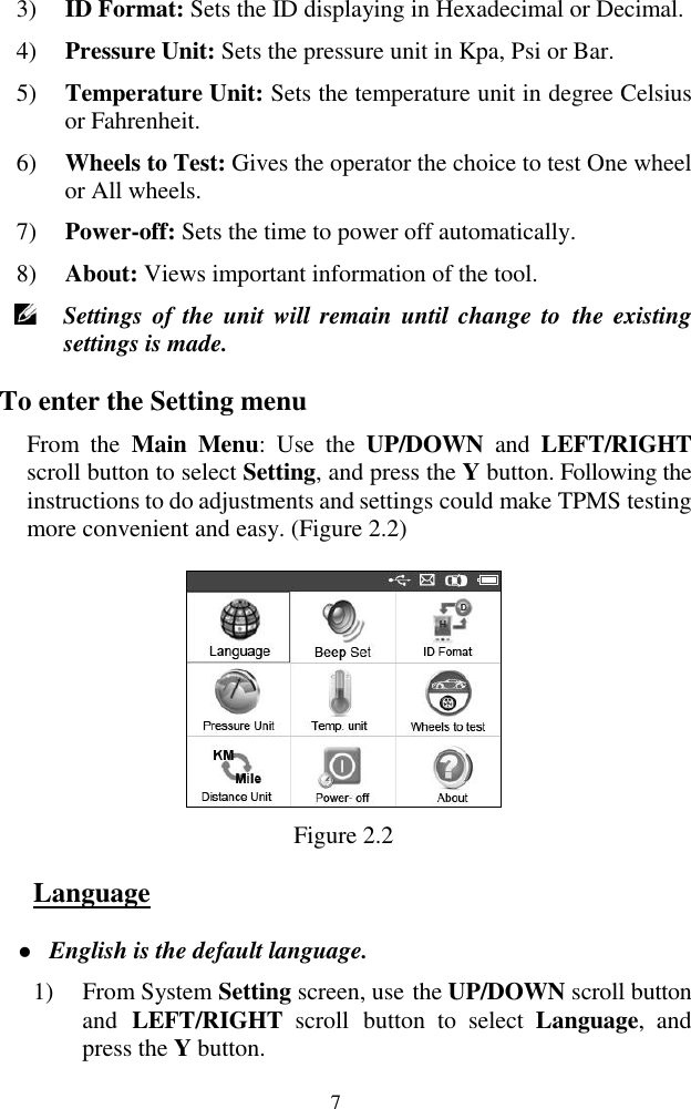
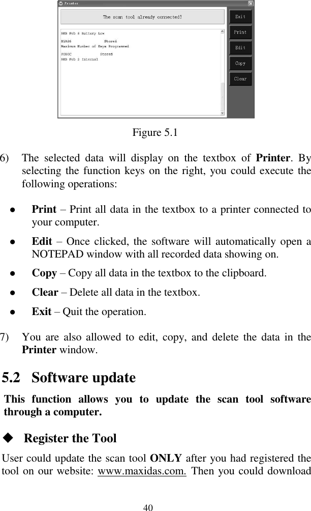
![45 Single updating Find the desired updating item and click the INSTALL button in the same line. With updating in progress, the INSTALL button changes to STOP. Check the updating process by observing the upper left progress bar [downloading] and upper right progress bar [installing]. You may also find progress information in the Status column of updated items. Anytime you could click the Pause button in the line to suspend this progress, and the state of this item would change to STOPPED. To resume updating process, click the INSTALL button in the line again. The progress will resume from the break point. When the downloading is completed, the downloaded program will be installed automatically. The new version will replace the old version. 4) Once the update is complete, disconnect the tool from the computer. It is now updated and ready to go. 5) For users who choose to update by SD card, please insert the SD card into the scan tool, and switch on the TPMS tool. It‟s now updated and ready to go. View or Delete Programs To view the list of installed programs or to delete an installed program, please follow these steps: Click on the Installed Programs tag entry and the page will show the list of programs installed. Select the program(s) that you would delete. Batch delete: Select the programs that you would delete by clicking on the check boxes to the left of those items. Then click the DELETE button on the right side of screen.](https://usermanual.wiki/Autel-Intelligent-Tech/3017501601/User-Guide-1874524-Page-46.png)