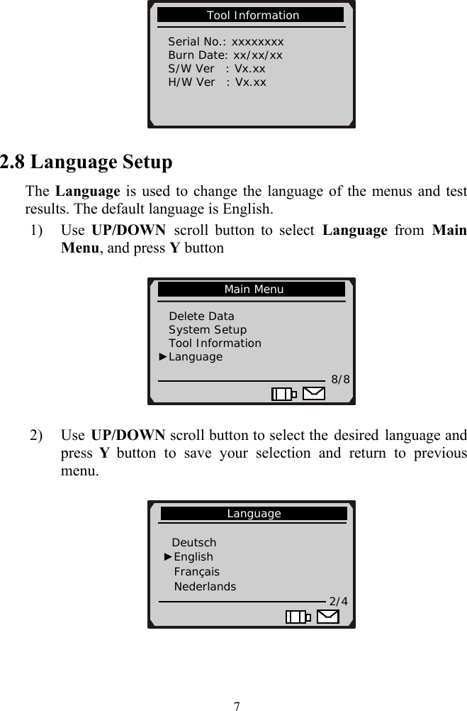
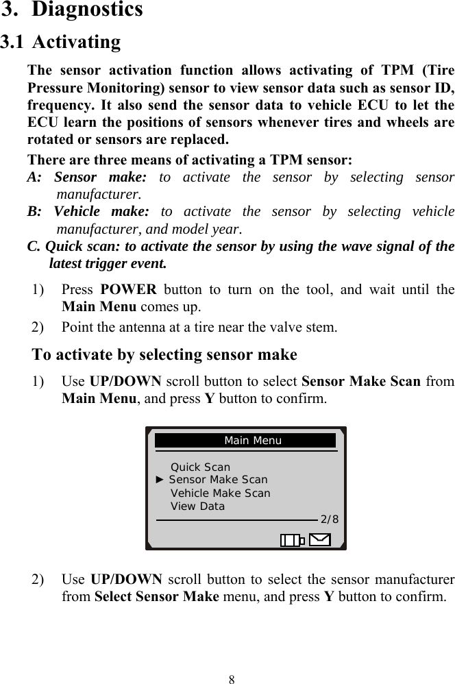
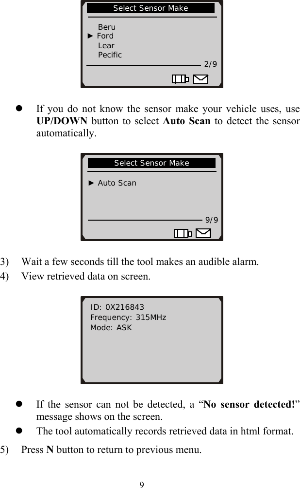
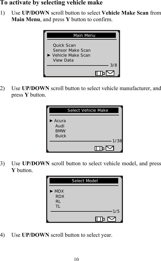
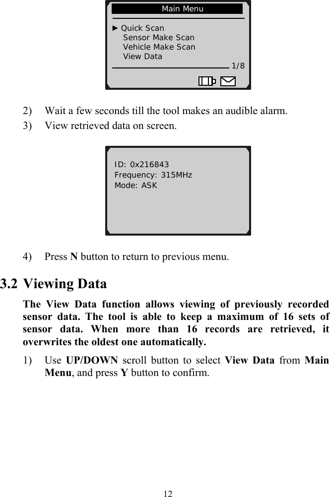
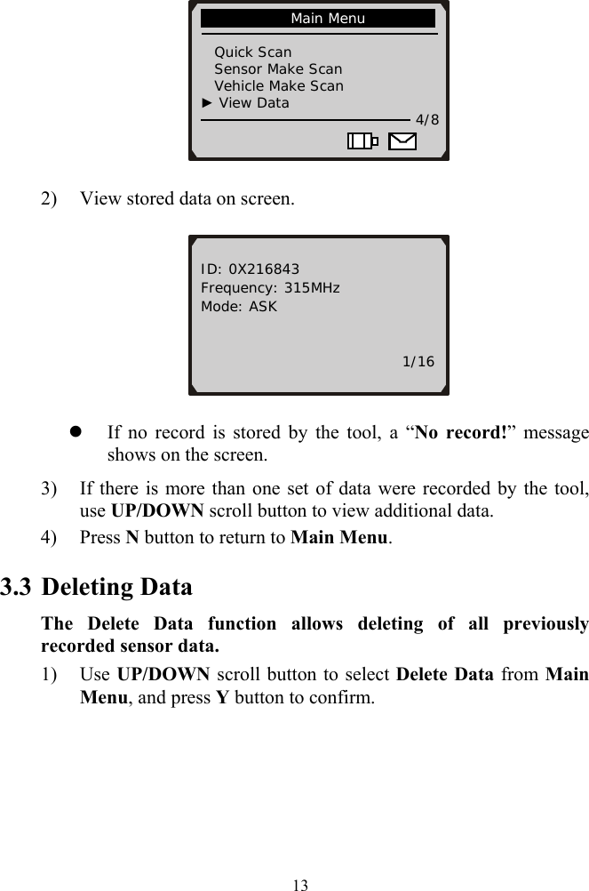
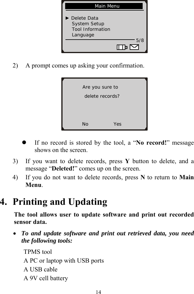
Autel Intelligent Tech 3017758521 TPMS diagnostic and service tool MaxiTPMS User Manual Table of Contents
Autel Intelligent Tech. Corp., Ltd. TPMS diagnostic and service tool MaxiTPMS Table of Contents
UserManual.wiki
>
Autel Intelligent Tech
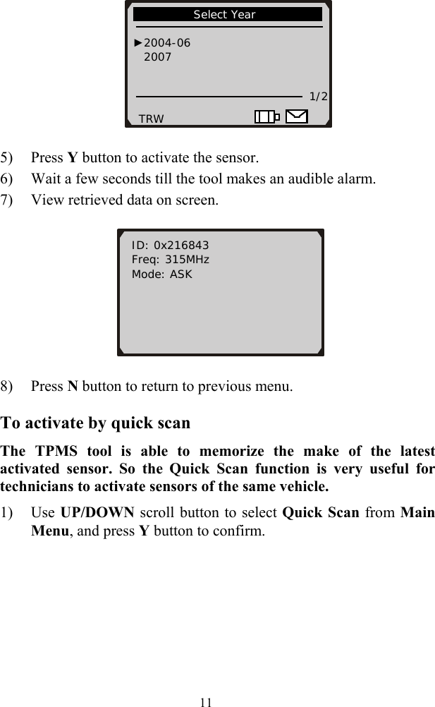
>
3017758521 User Manual
Users Manual
Navigation menu
Upload a User Manual
Namespaces
Wiki Guide
HTML
PDF
Info
Views
User Manual
Discussion / Help
Navigation