Autel Intelligent Tech 301RC58A1 EZ-Fly User Manual
Autel Intelligent Tech. Corp., Ltd. EZ-Fly
UserManual.wiki
>
Autel Intelligent Tech
>
301RC58A1 User Manual
Users Manual
Navigation menu
Upload a User Manual
Namespaces
Wiki Guide
HTML
PDF
Info
Views
User Manual
Discussion / Help
Navigation
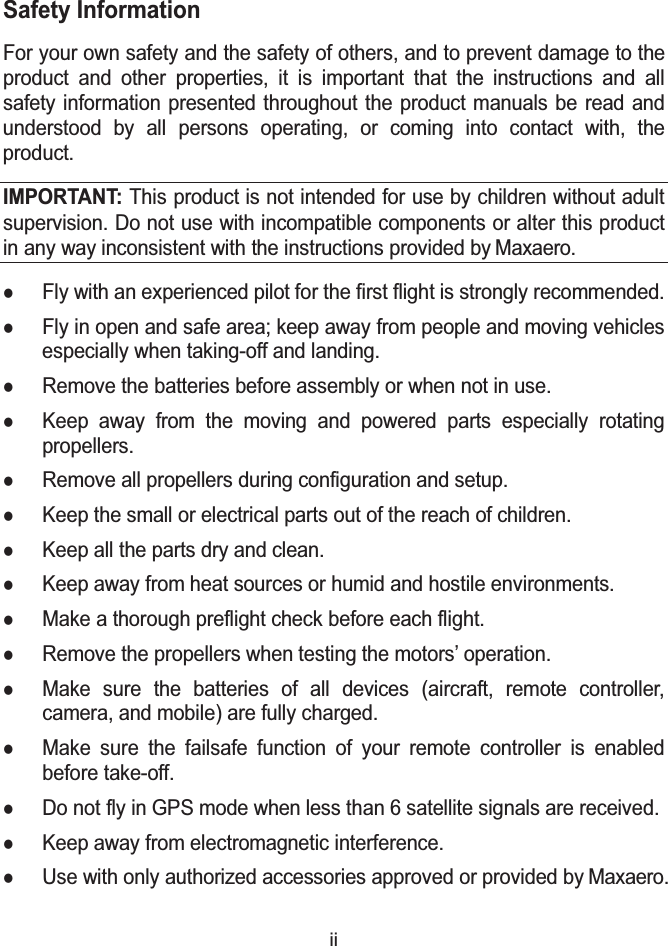

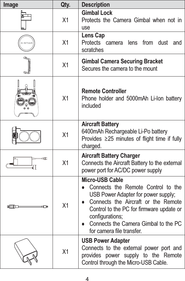
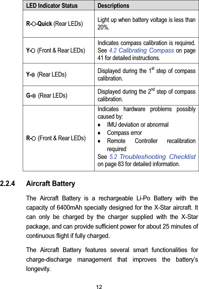
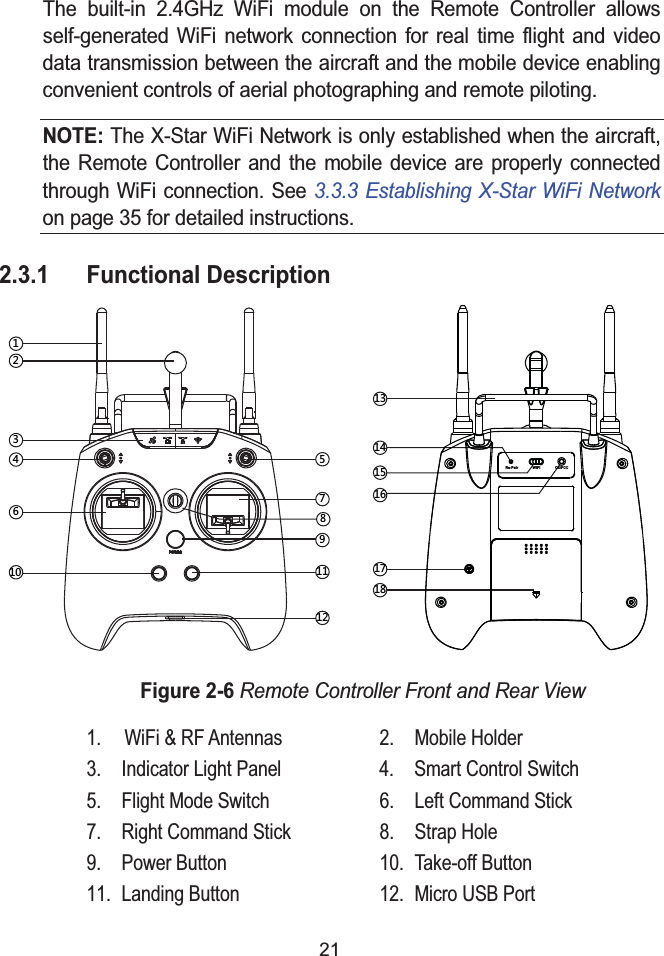
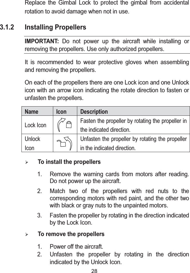
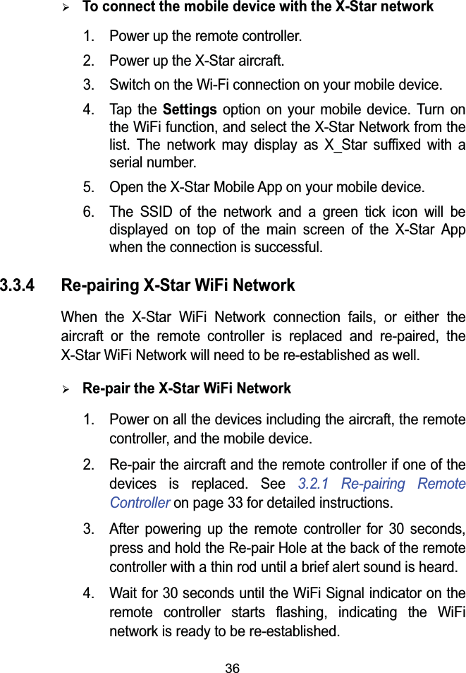
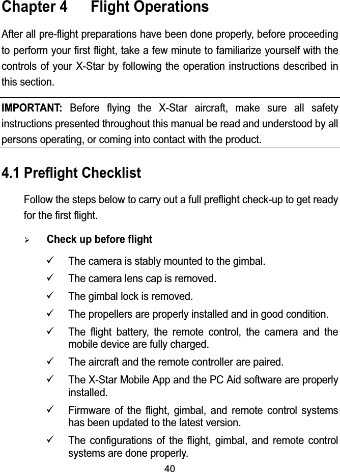
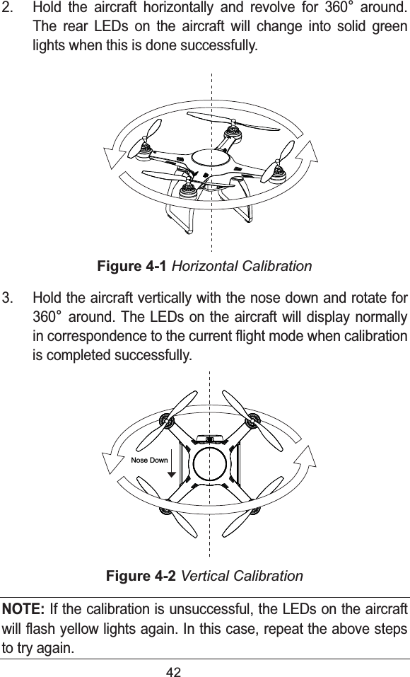
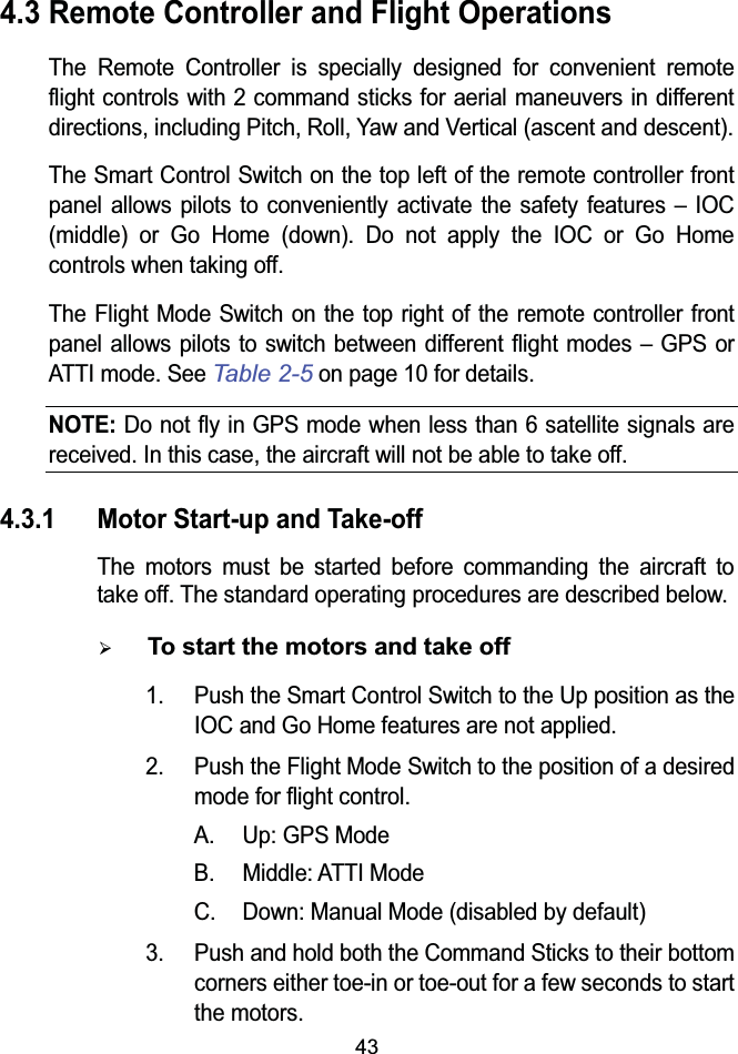
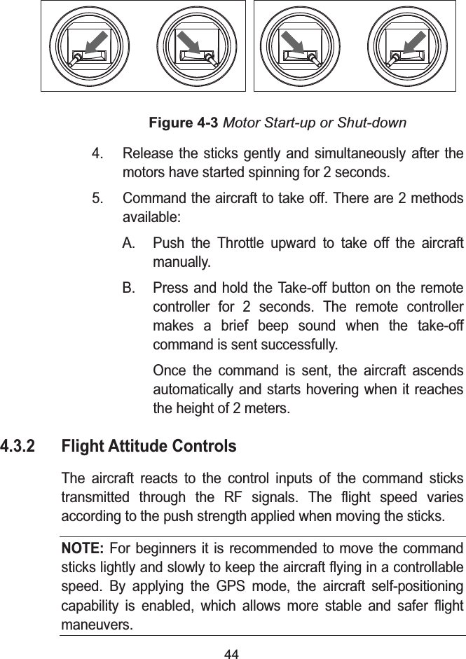
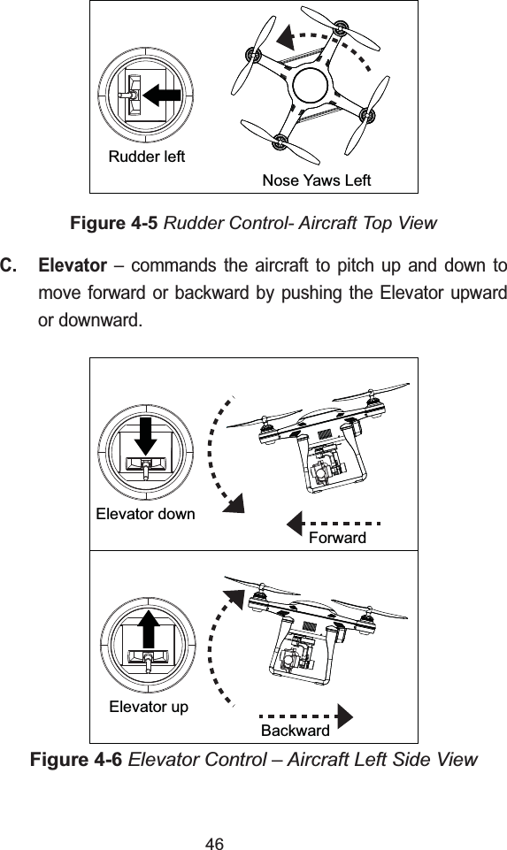
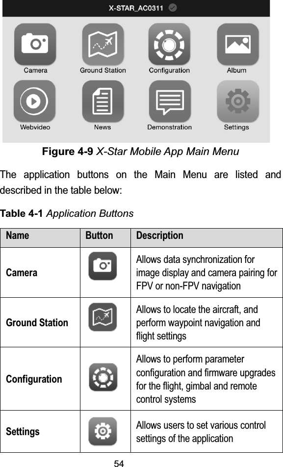
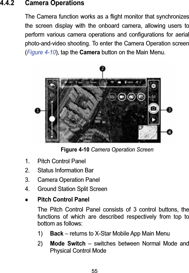
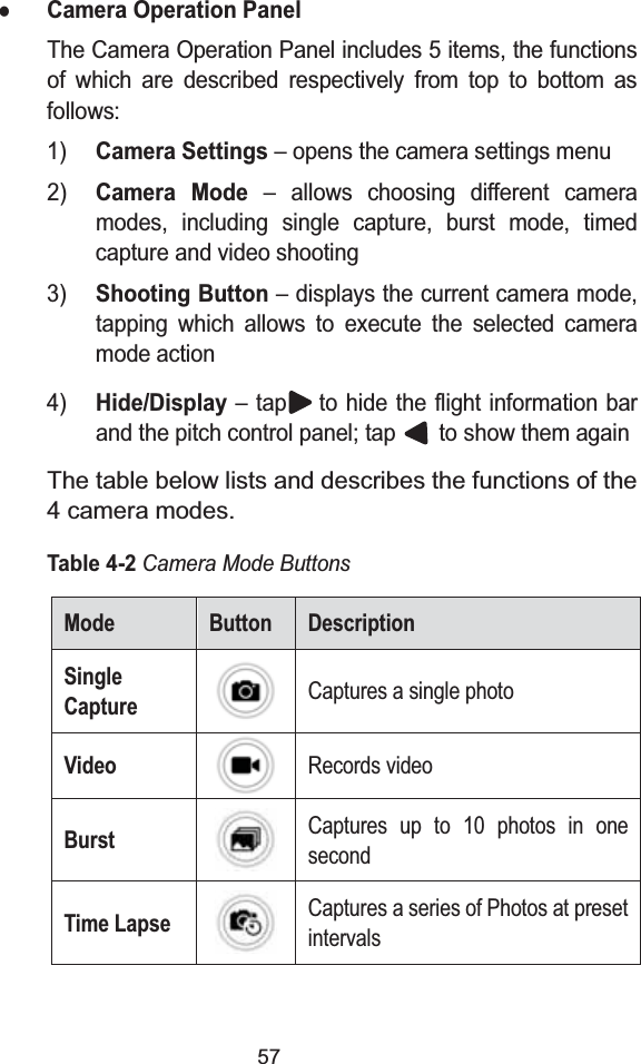
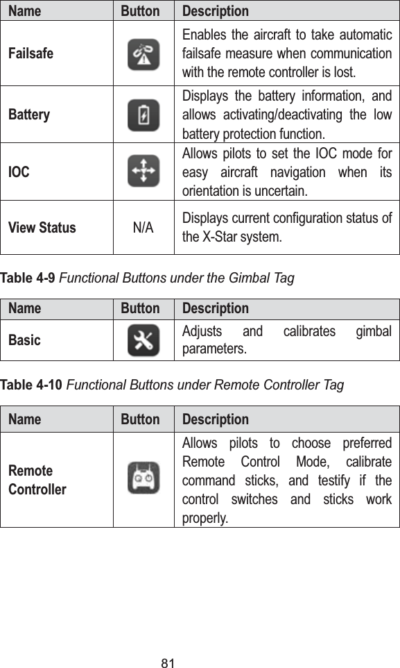
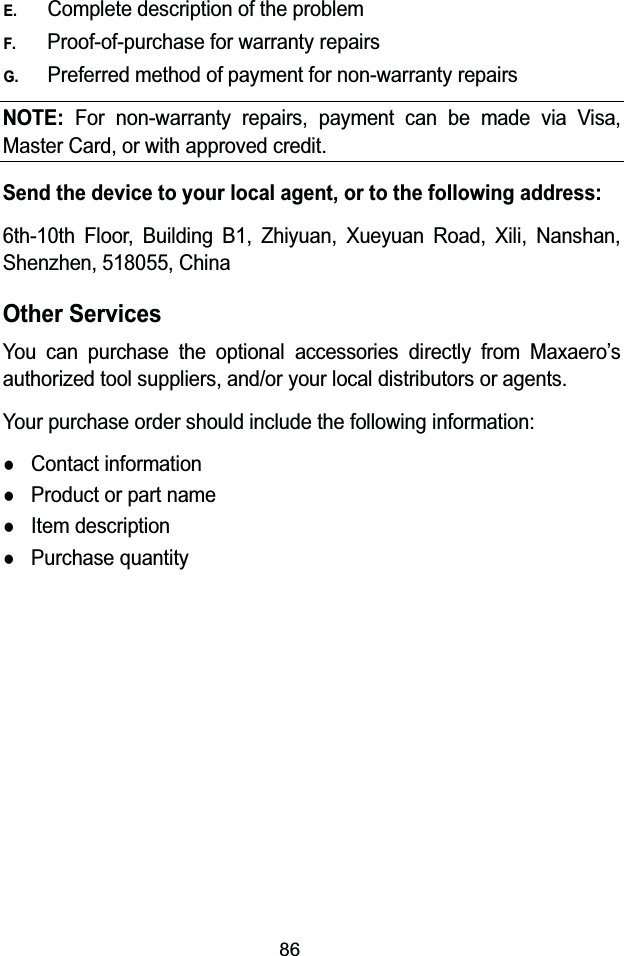
![45The 4 primary flight controls include:A. Throttle– commands the aircraft to ascend by pushing the stick upward, and descend by pushing it downward.Figure 4-4 Throttle Control – Aircraft Left Side ViewB. Rudder – commands the aircraft to yaw left or right bypushing the Rudder left or right.:NXUZZRK[V )ROSH:NXUZZRKJU]T*KYIKTJNose Yaws RightRudder right](https://usermanual.wiki/Autel-Intelligent-Tech/301RC58A1/User-Guide-2563588-Page-51.png)