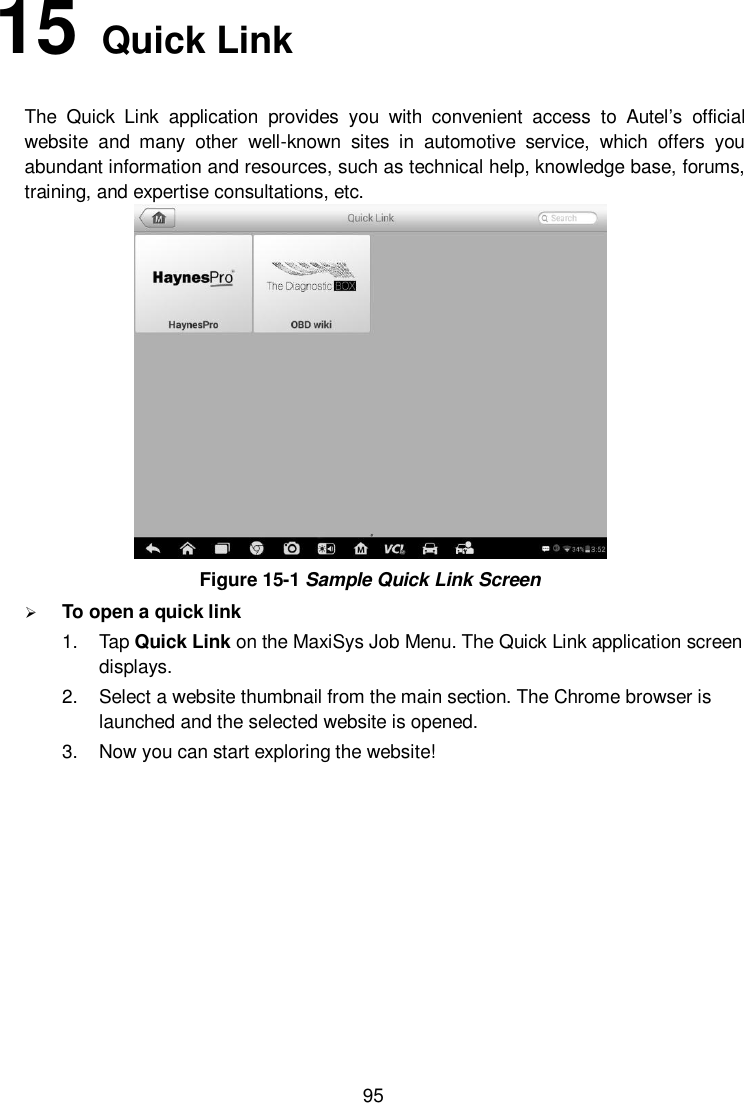
Autel Intelligent Tech MAXISYSMS908S Automotive Diagnostic & Analysis System User Manual 6 Specification ok
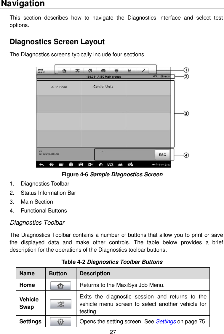
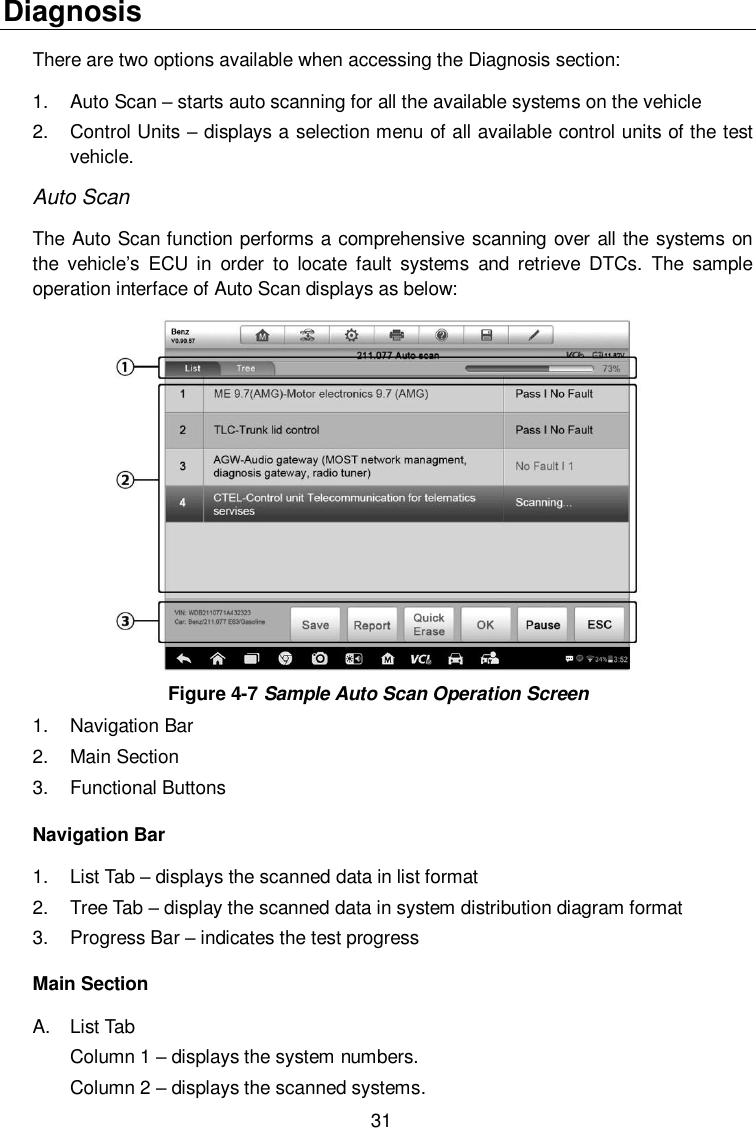
Autel Intelligent Tech. Corp., Ltd. Automotive Diagnostic & Analysis System 6 Specification ok
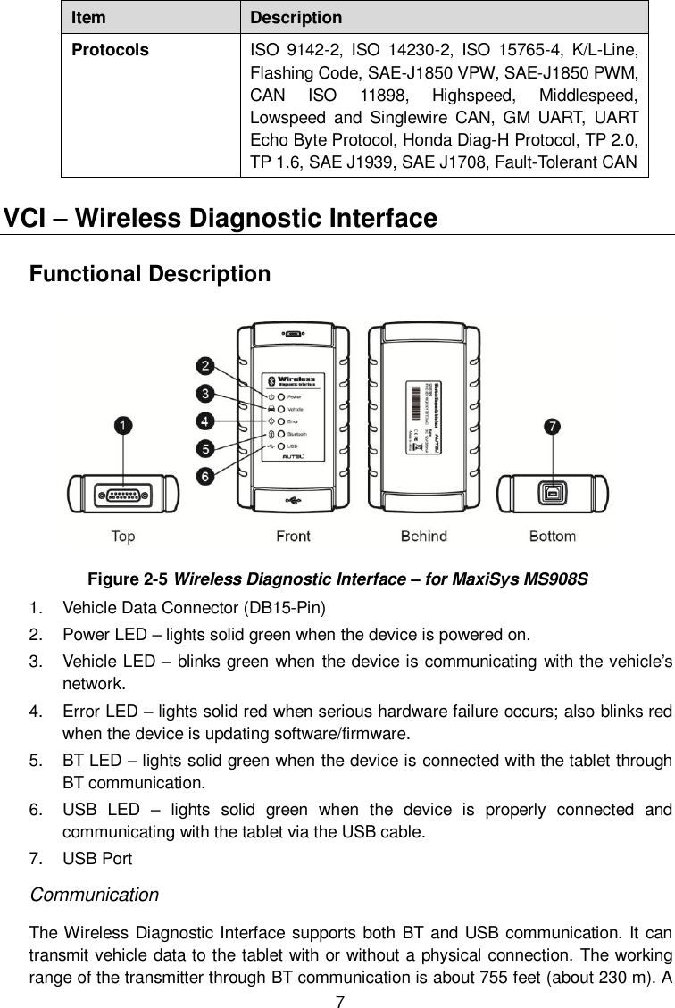
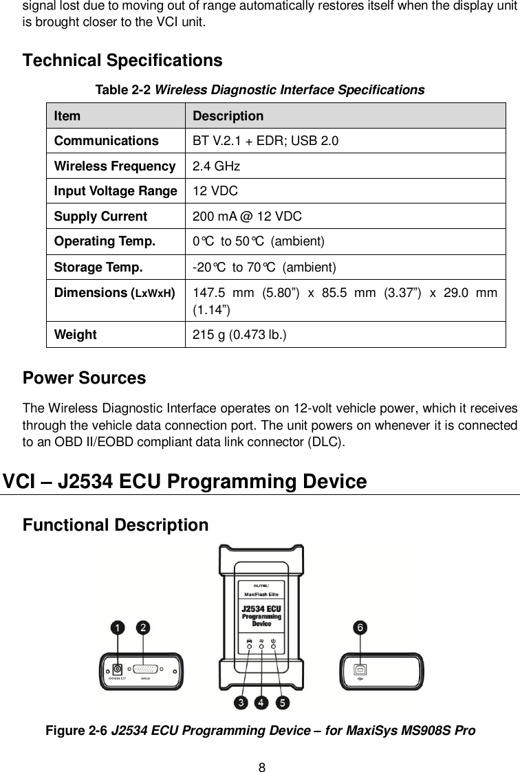
Contents
- 1. Users Manual
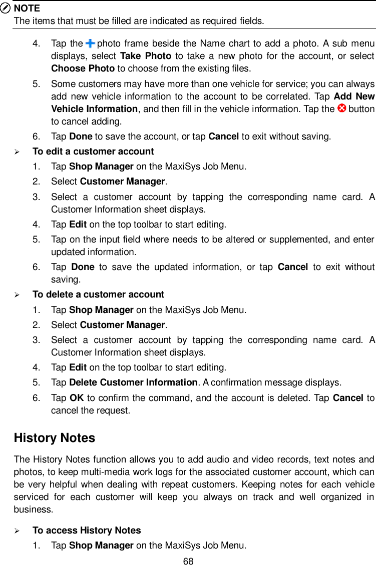
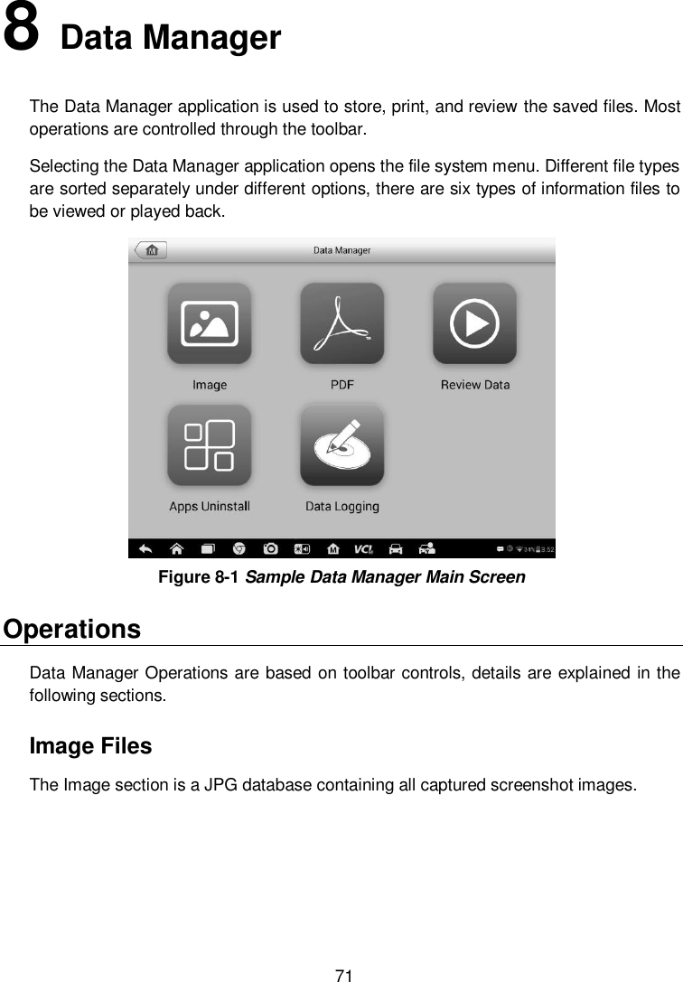
- 2. User Manual
- 3. User Manaul
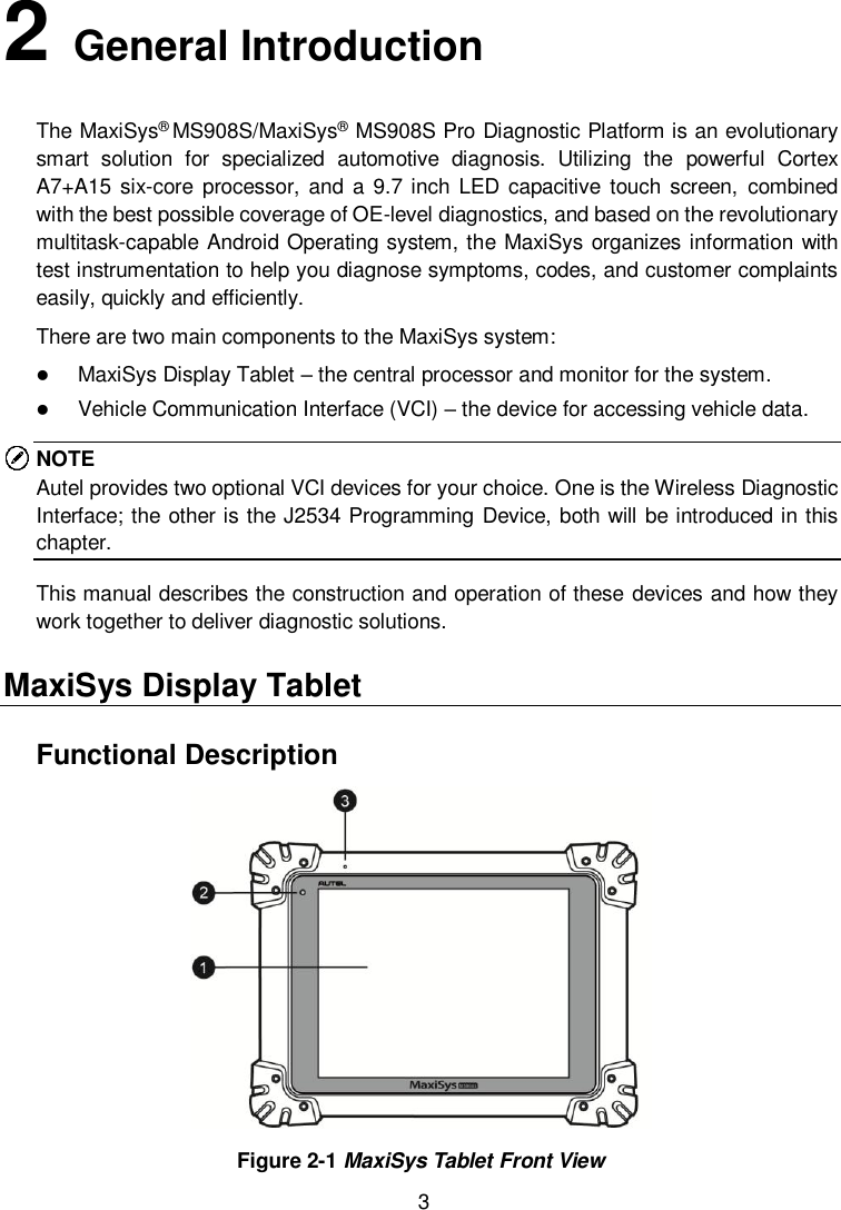
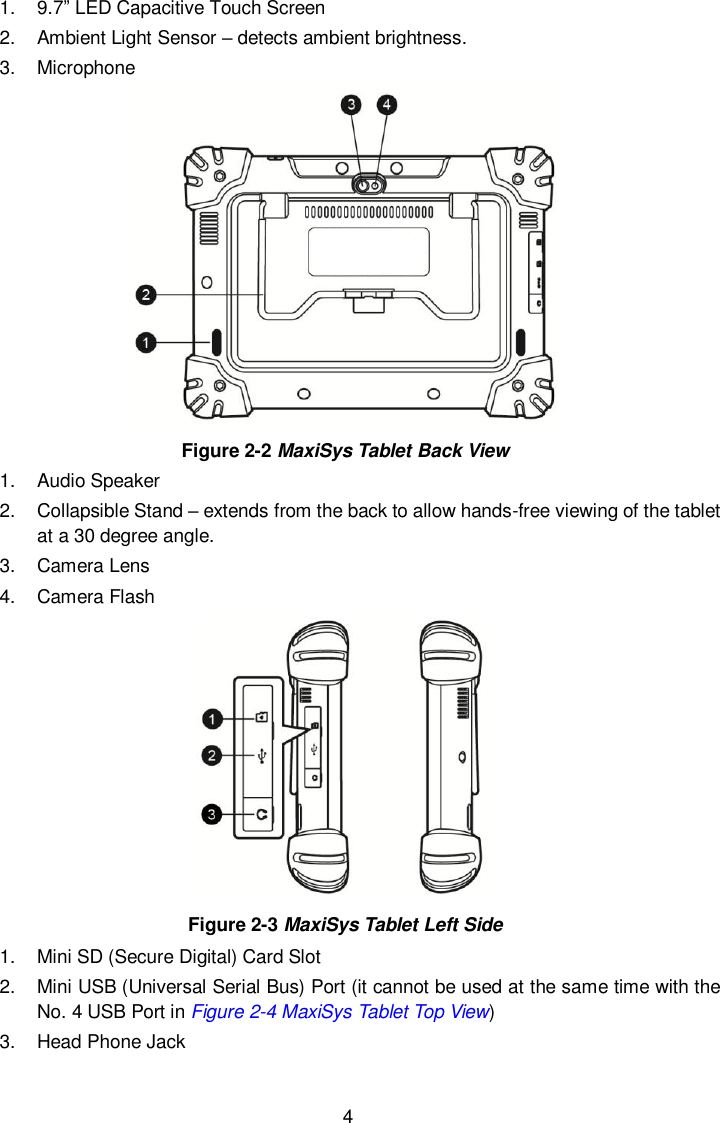
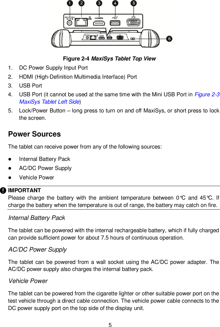
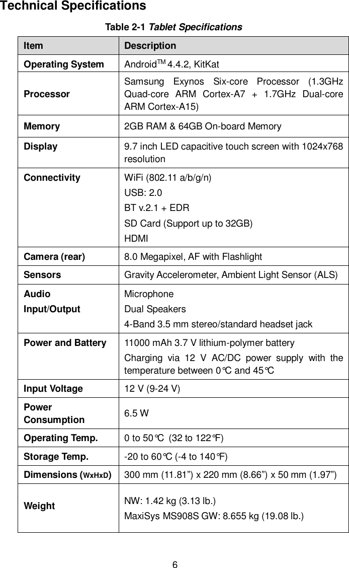
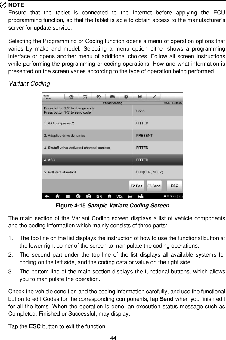
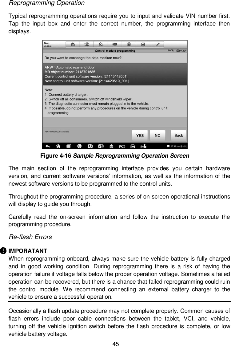
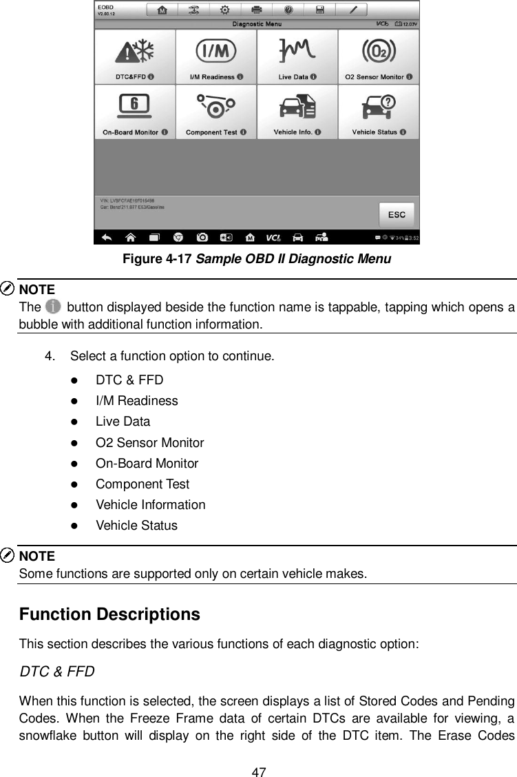
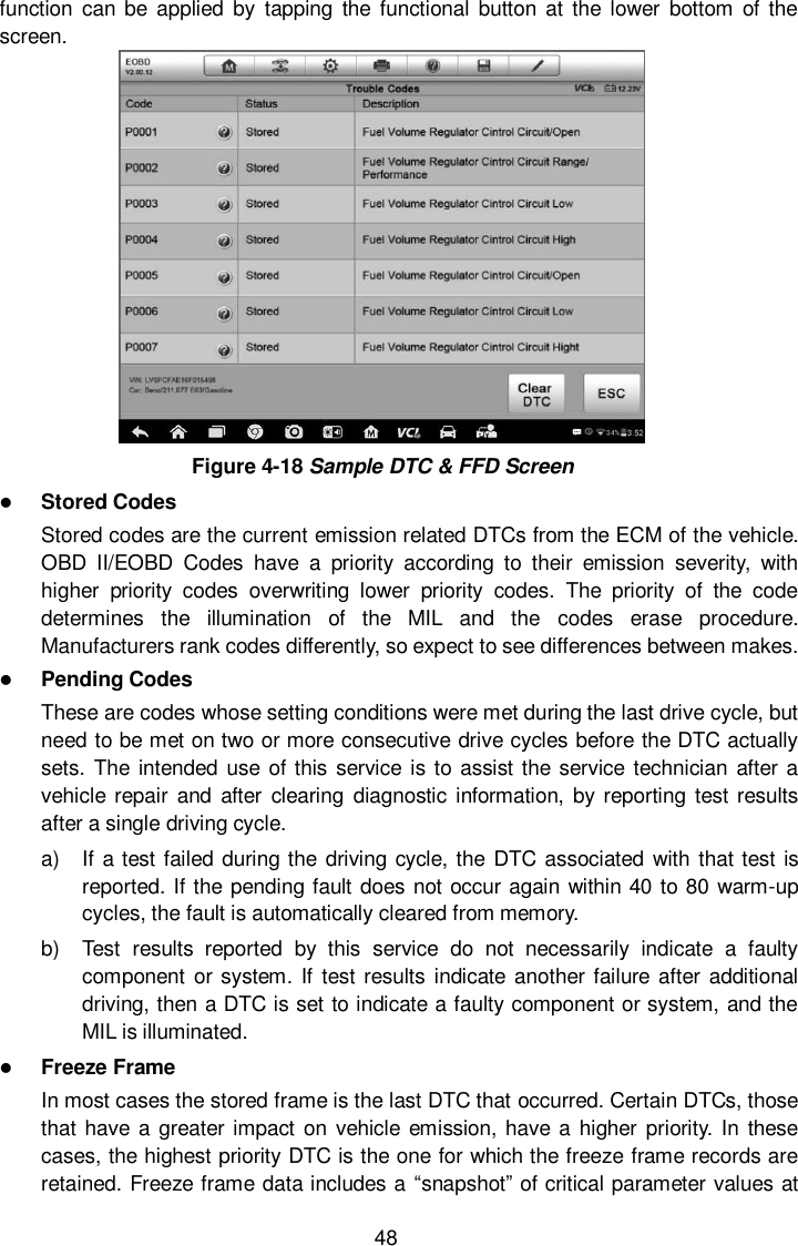
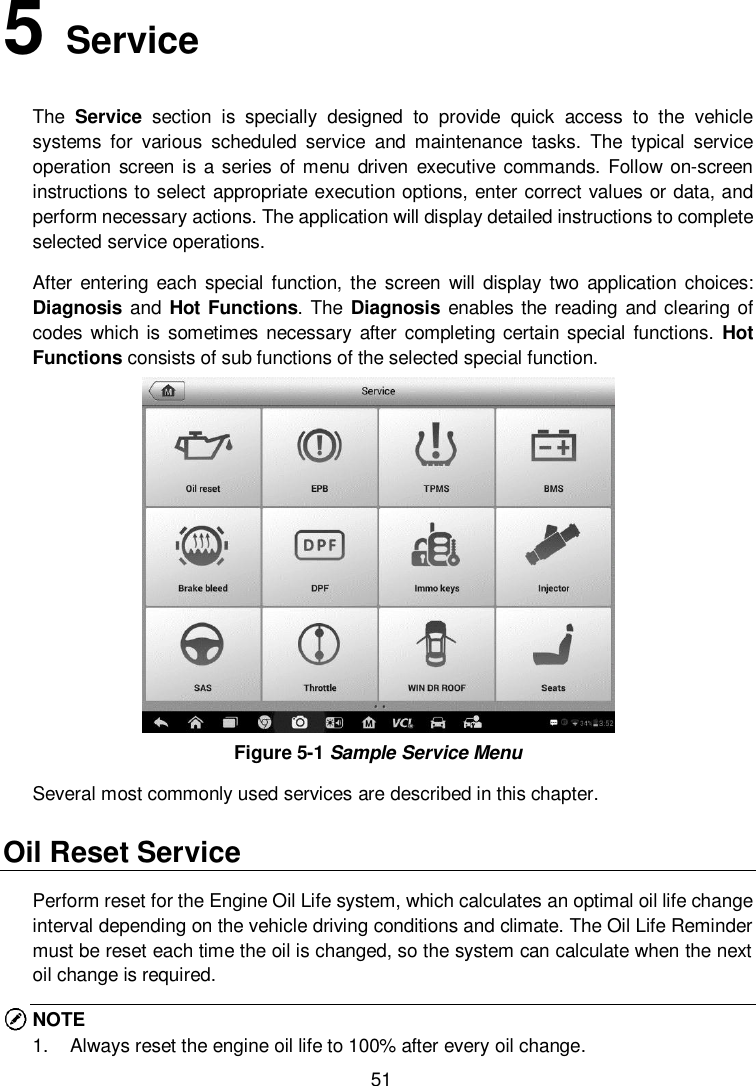
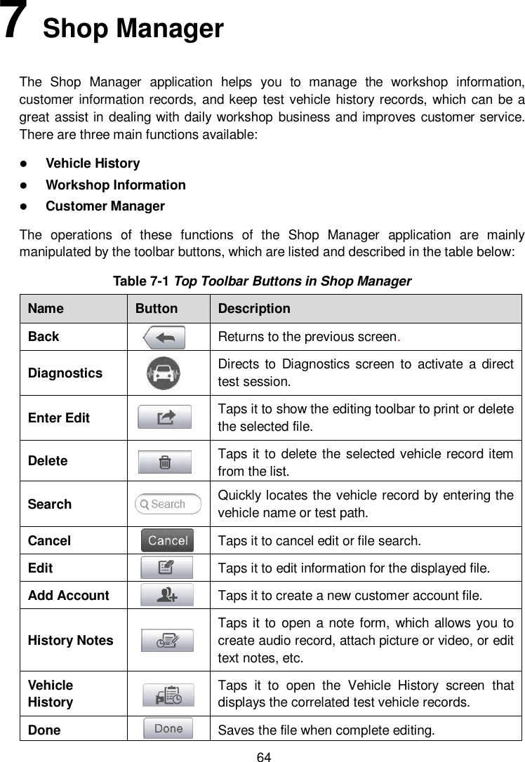
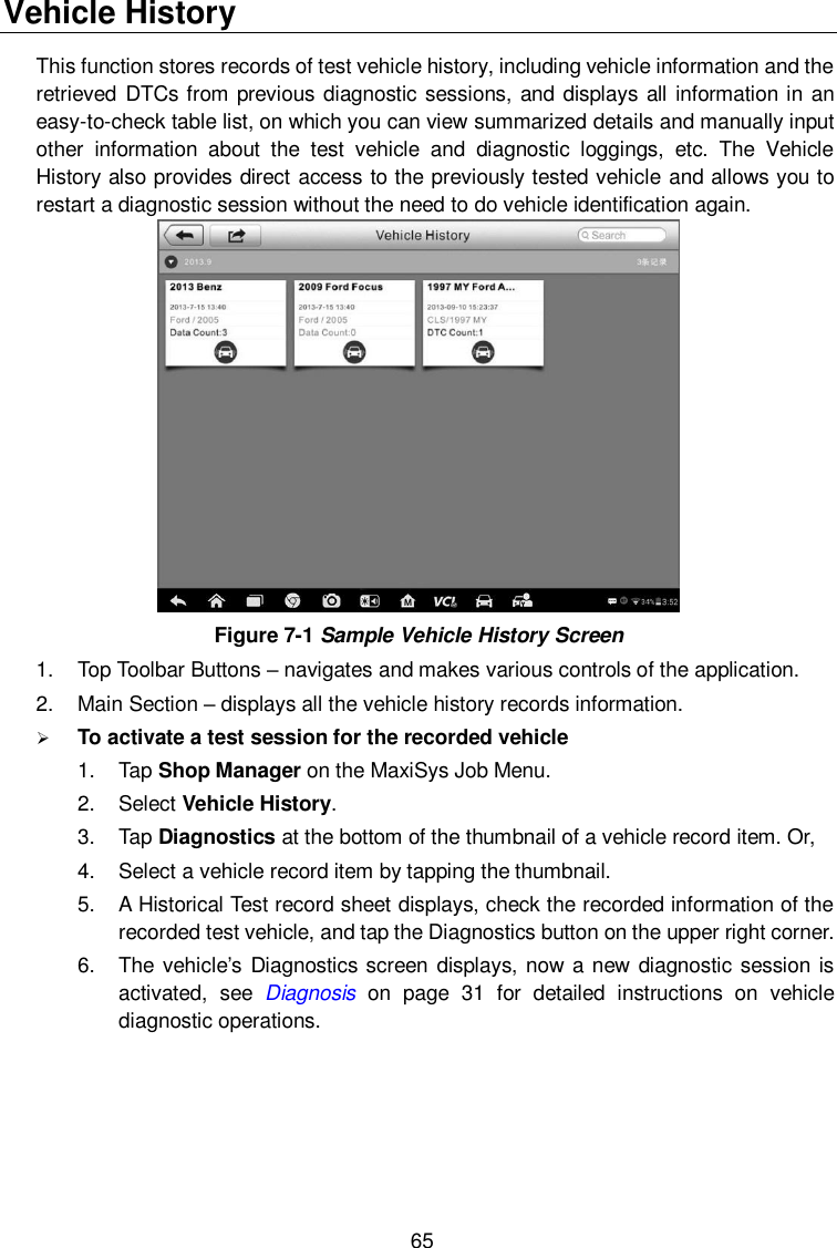
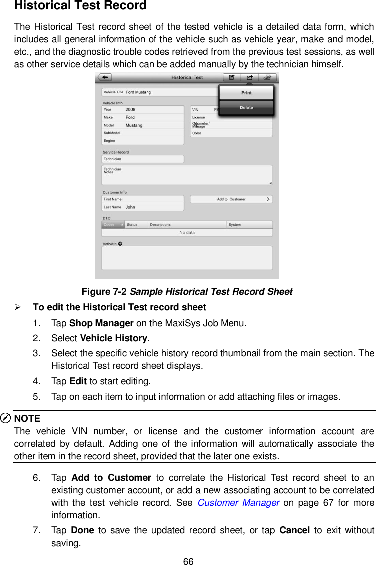
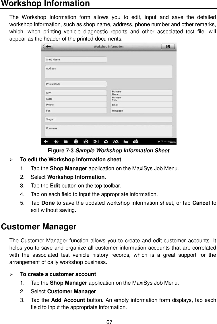
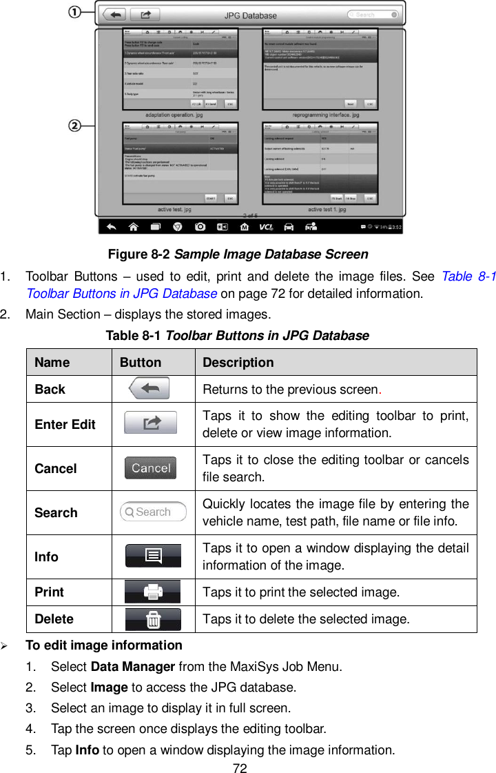
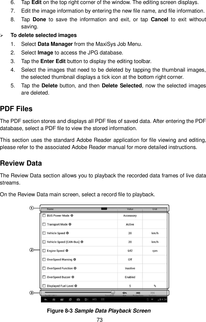
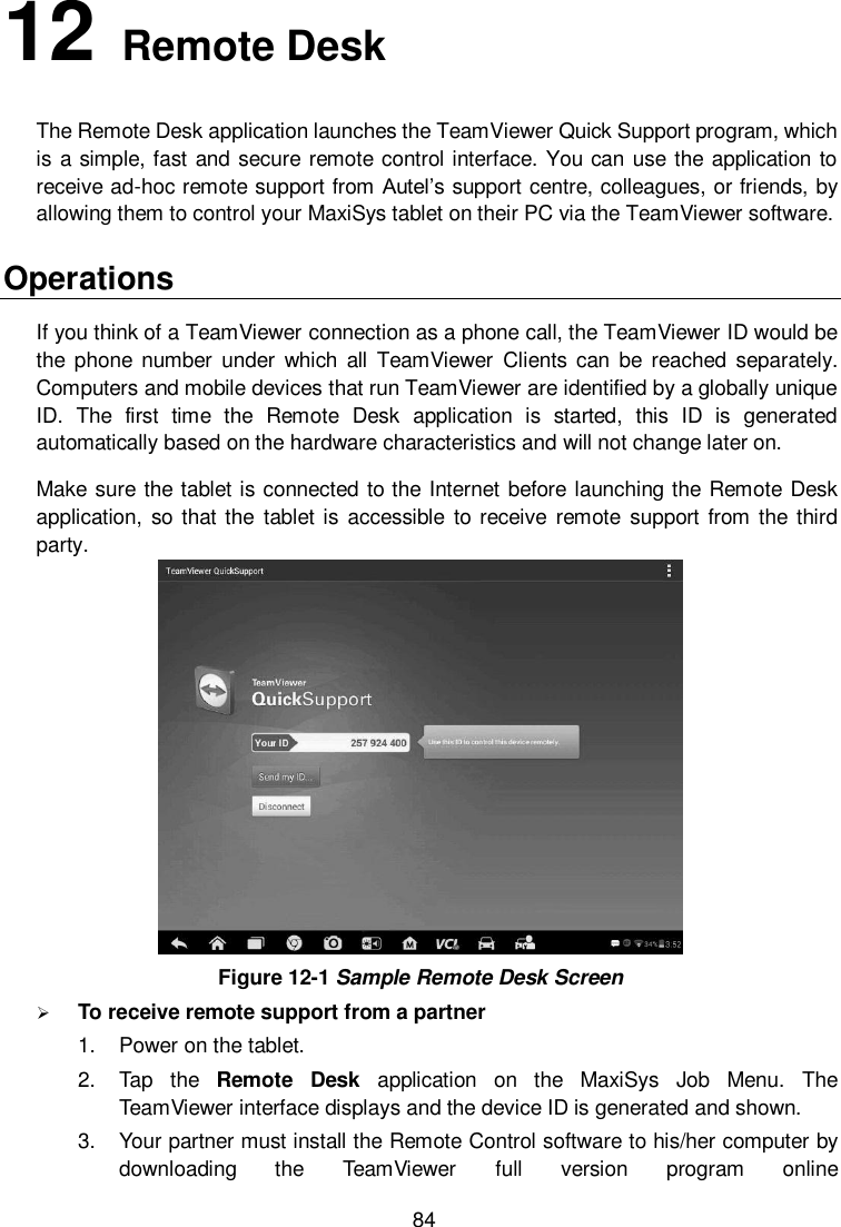
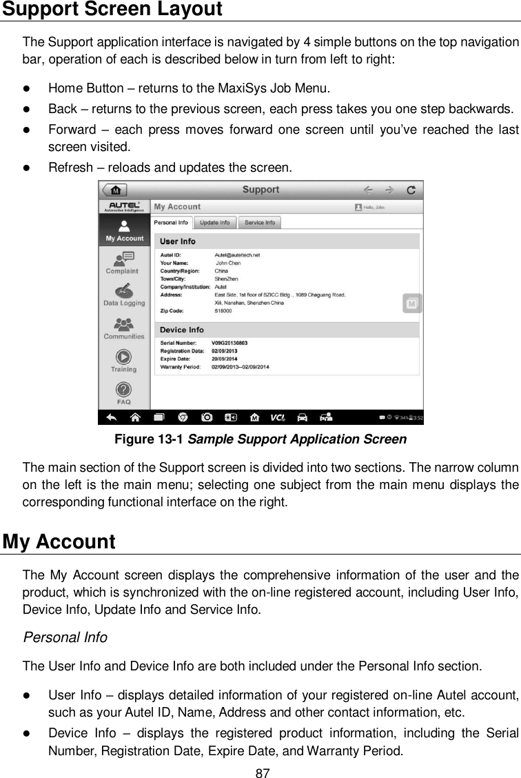
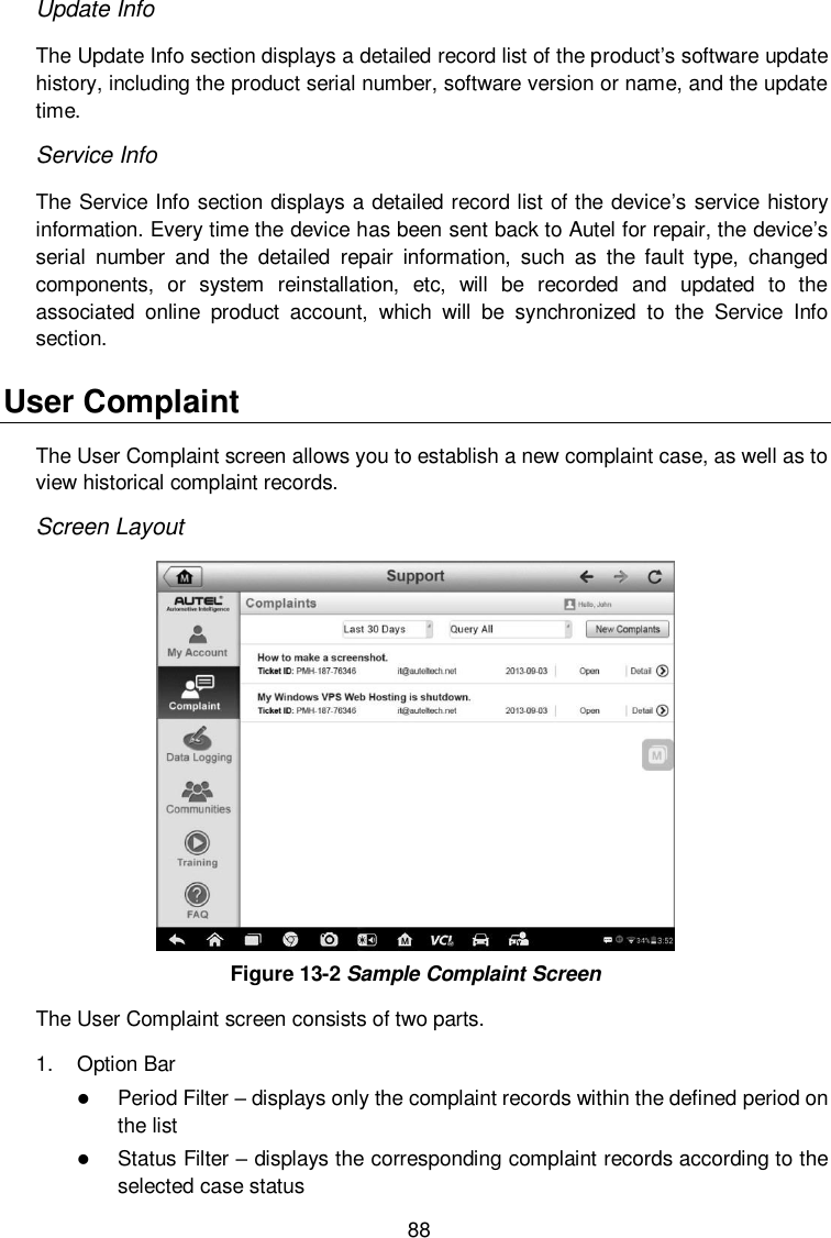
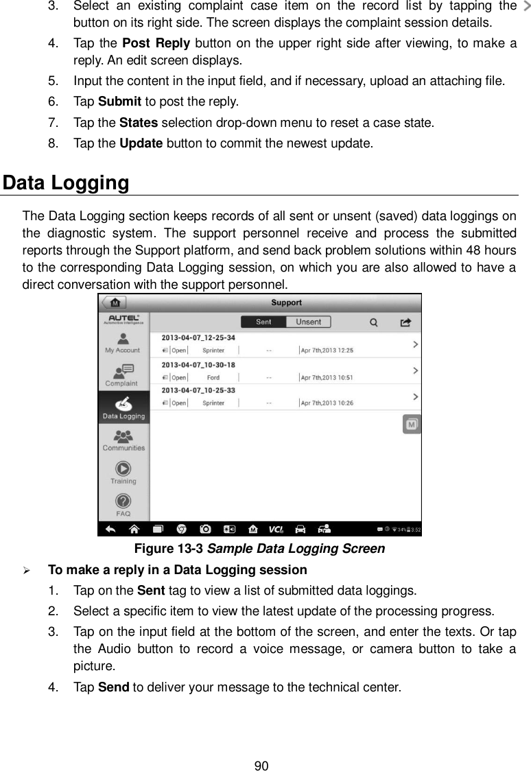
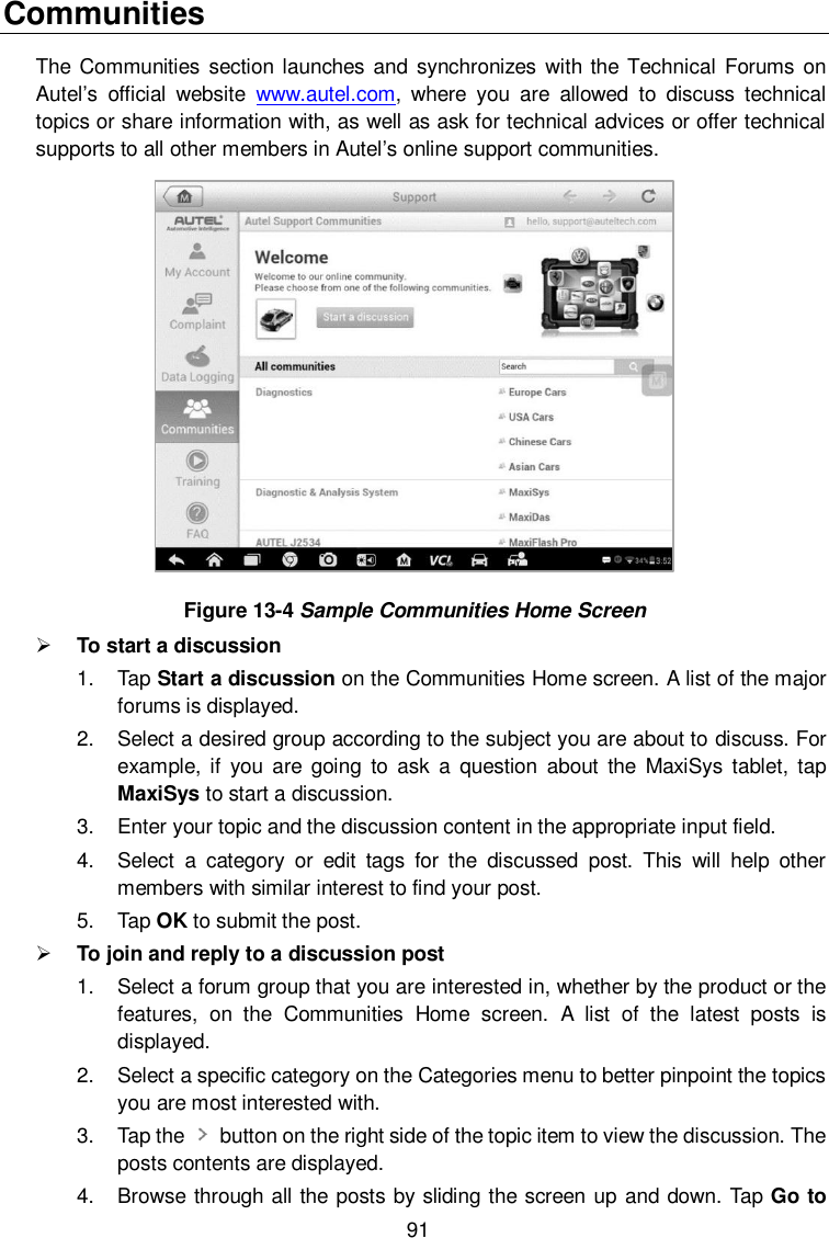
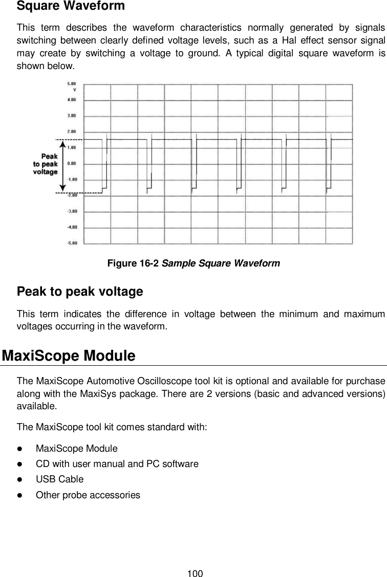
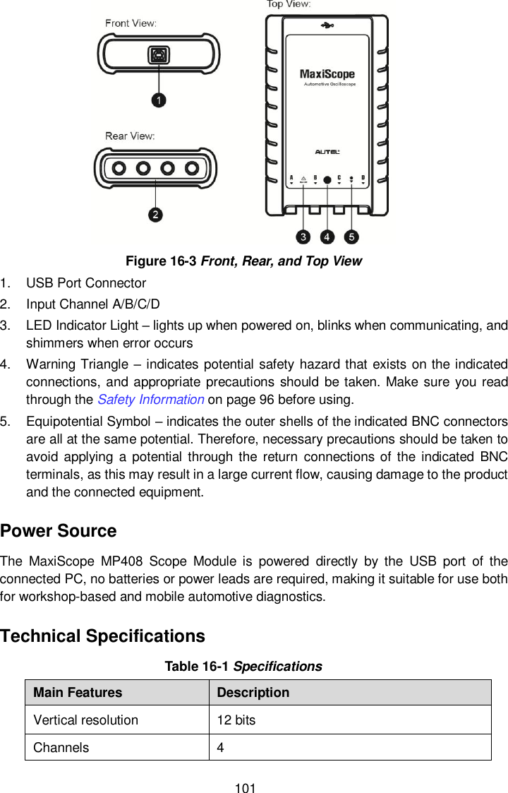
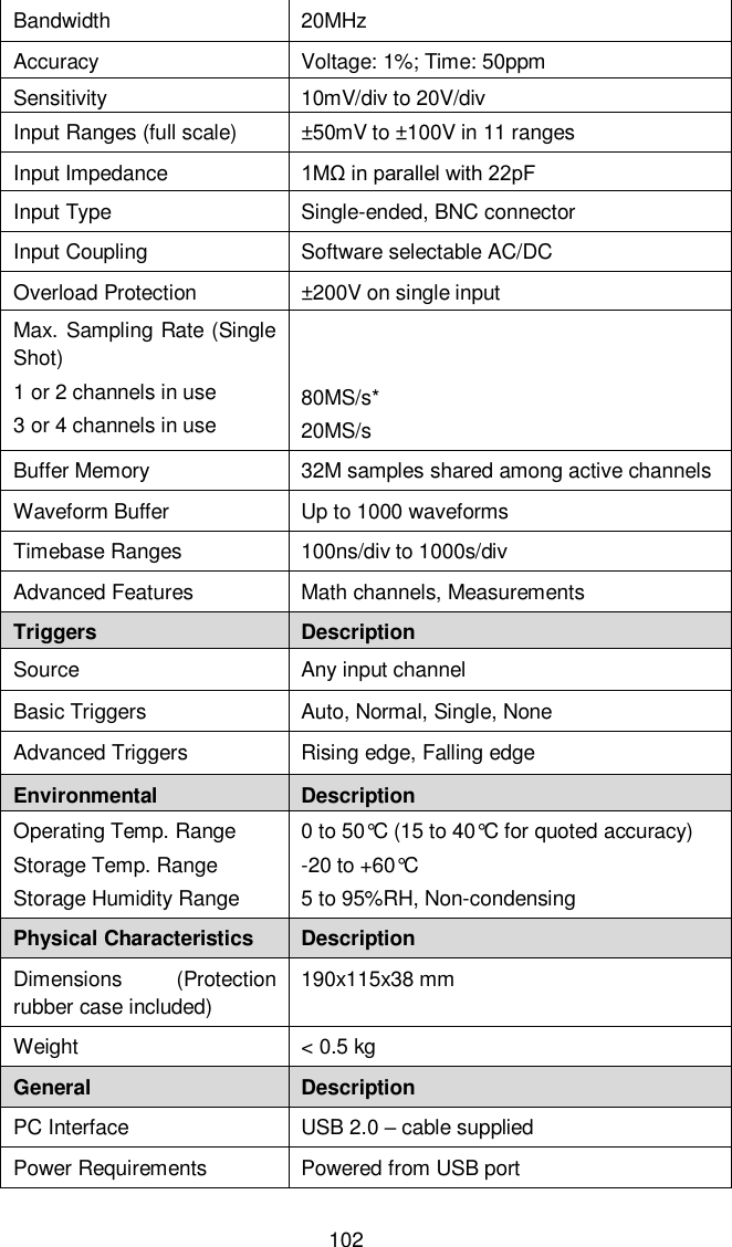
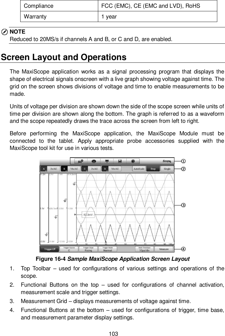
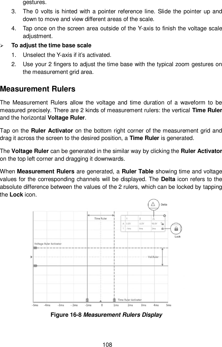
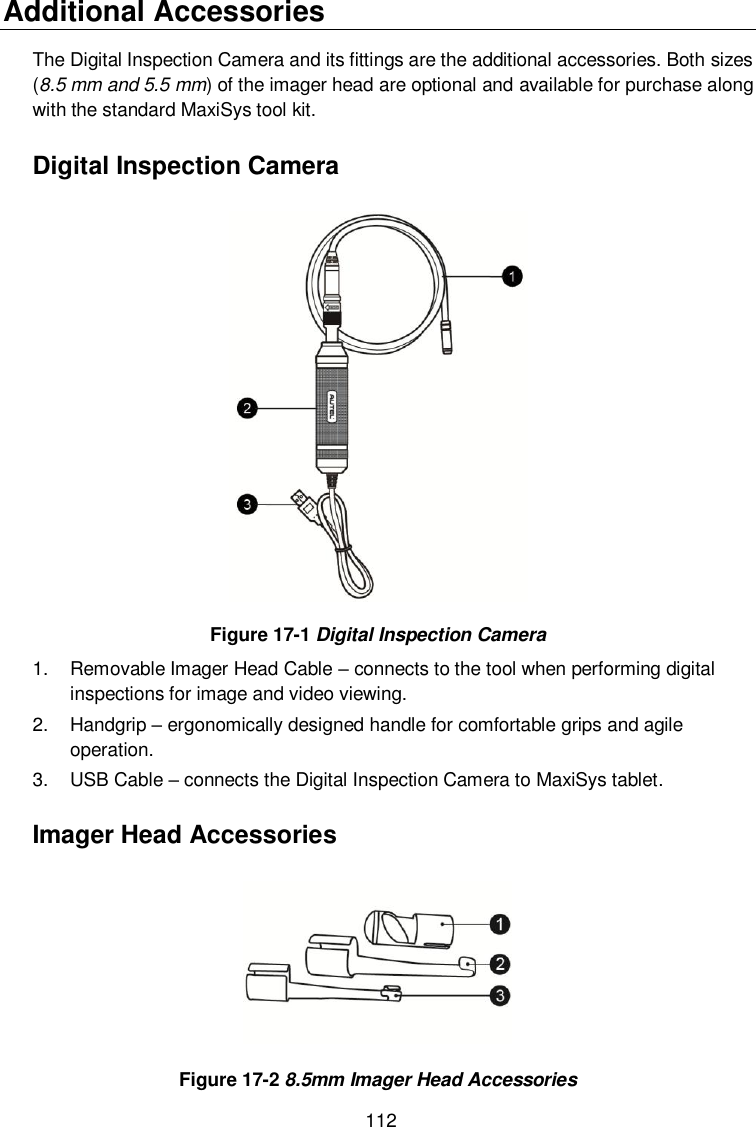
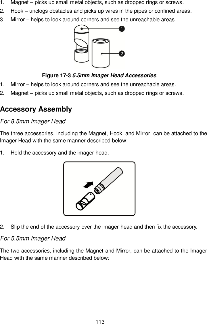
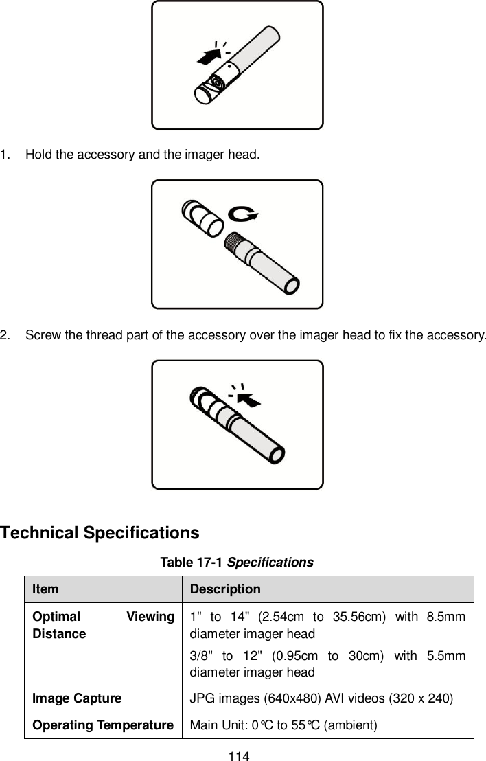
User Manual