Autel Intelligent Tech MAXISYSMY905 MaxiSys Mini User Manual
Autel Intelligent Tech. Corp., Ltd. MaxiSys Mini
UserManual.wiki
>
Autel Intelligent Tech
>
MAXISYSMY905 User Manual
User manual
Navigation menu
Upload a User Manual
Namespaces
Wiki Guide
HTML
PDF
Info
Views
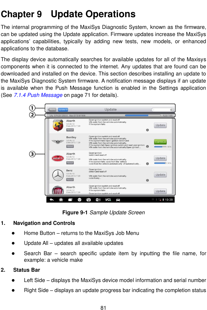
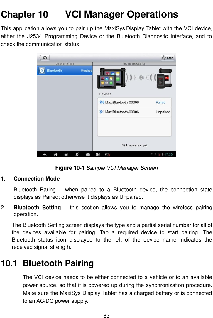
User Manual
Discussion / Help
Navigation