Autel Intelligent Tech MX808-TPMS COMPREHENSIVE TPMS TOOL User Manual
Autel Intelligent Tech. Corp., Ltd. COMPREHENSIVE TPMS TOOL Users Manual
UserManual.wiki
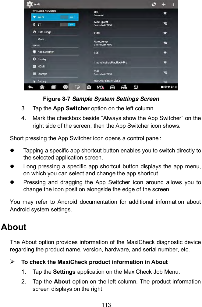
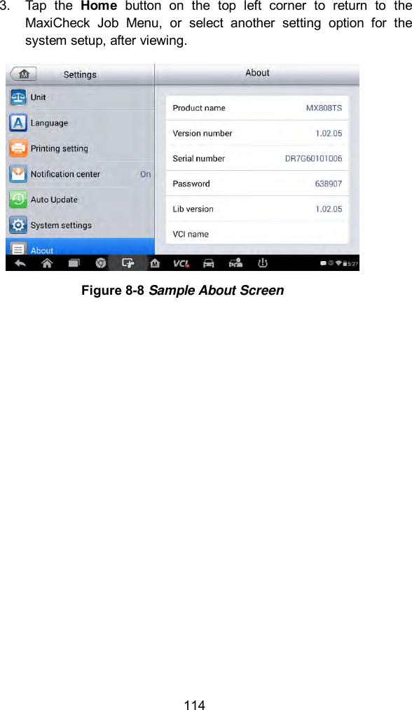
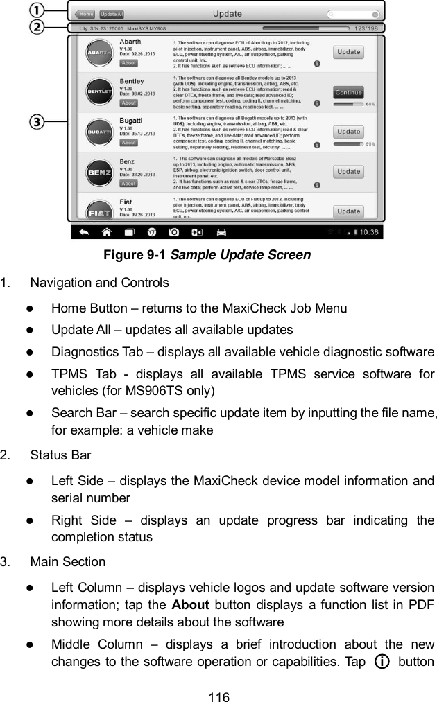
>
Autel Intelligent Tech
>
MX808-TPMS User Manual
>
Users Manual
Contents
1.
Test Setup Photos
2.
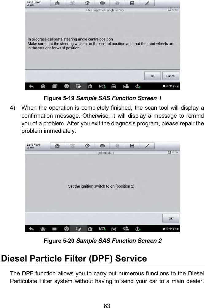
Users Manual
Users Manual
Navigation menu
Upload a User Manual
Namespaces
Wiki Guide
HTML
PDF
Info
Views
User Manual
Discussion / Help
Navigation
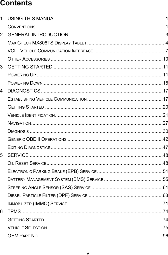
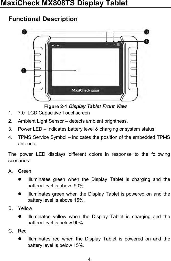
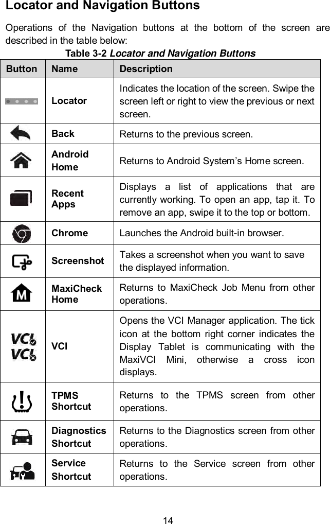
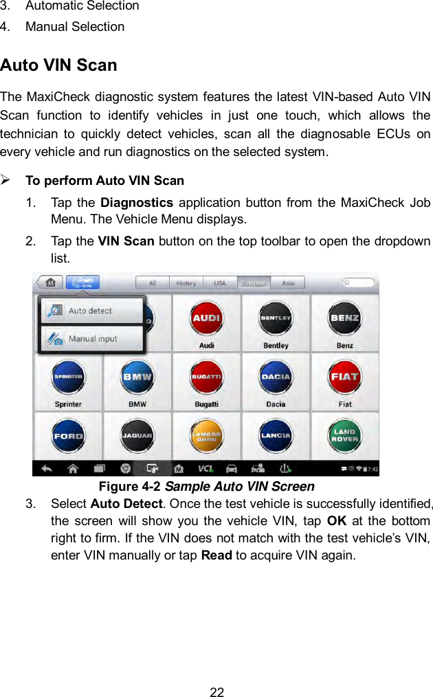
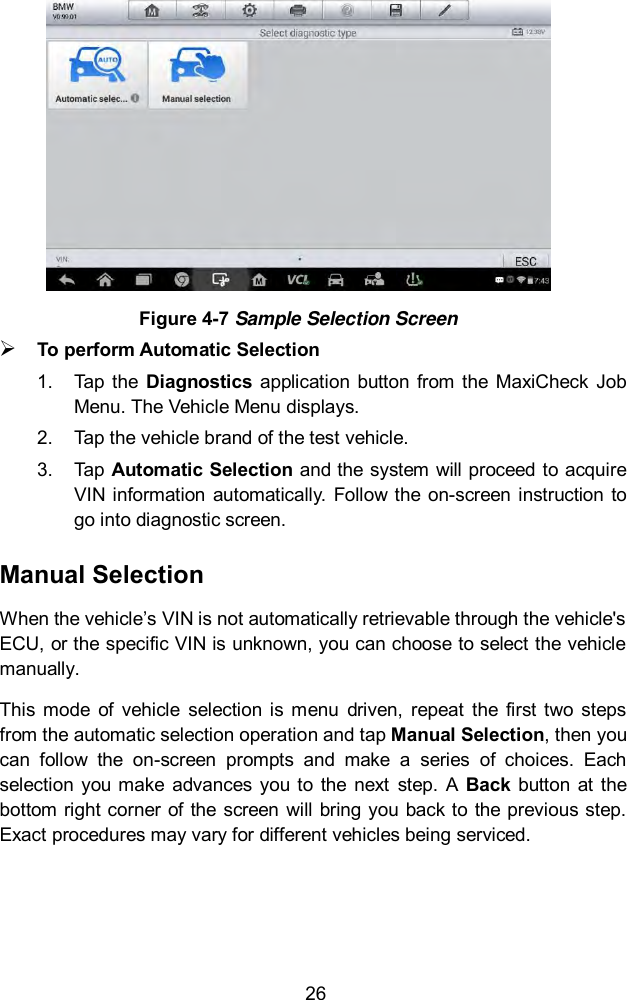
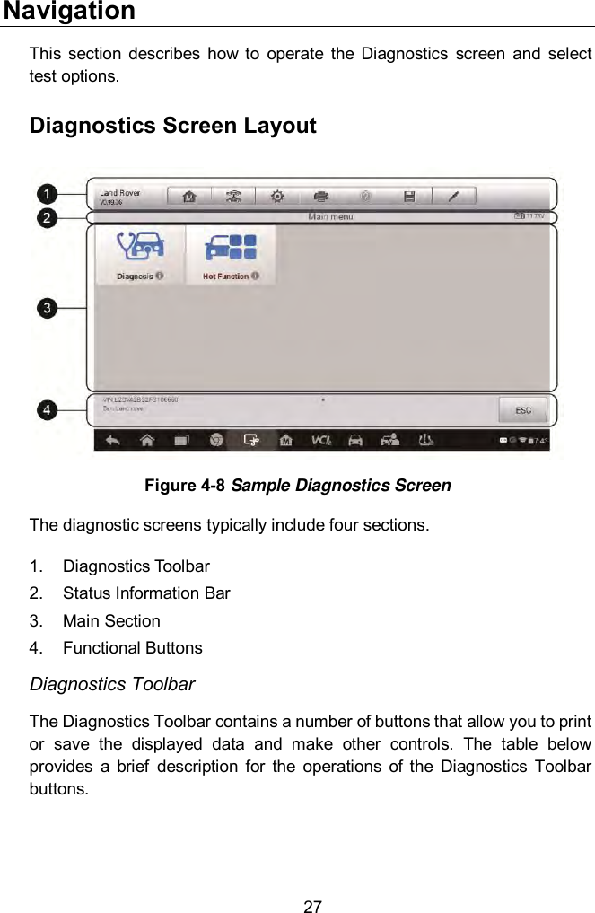
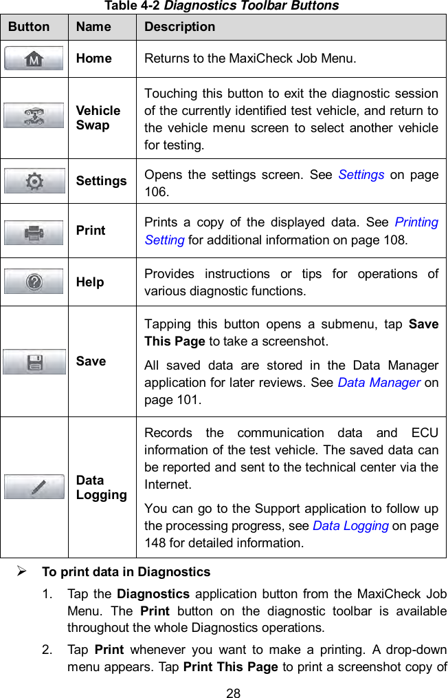
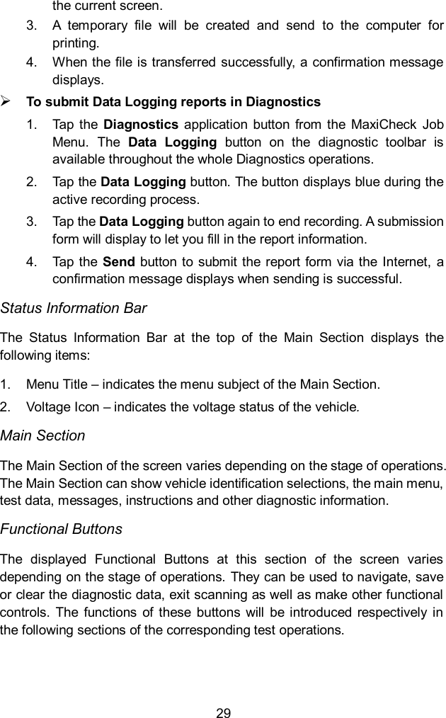
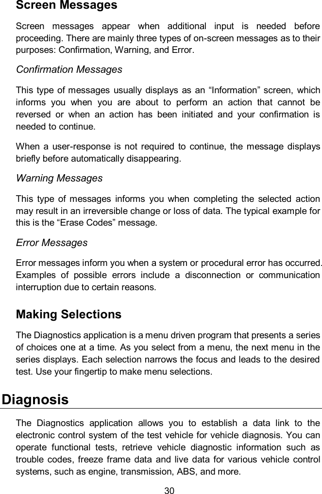
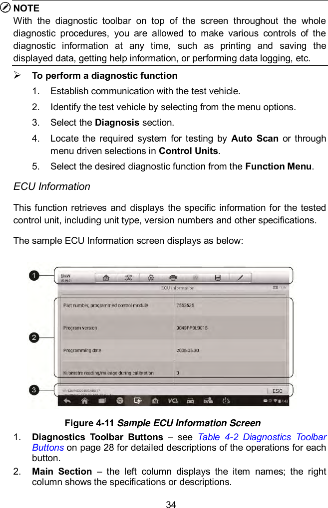
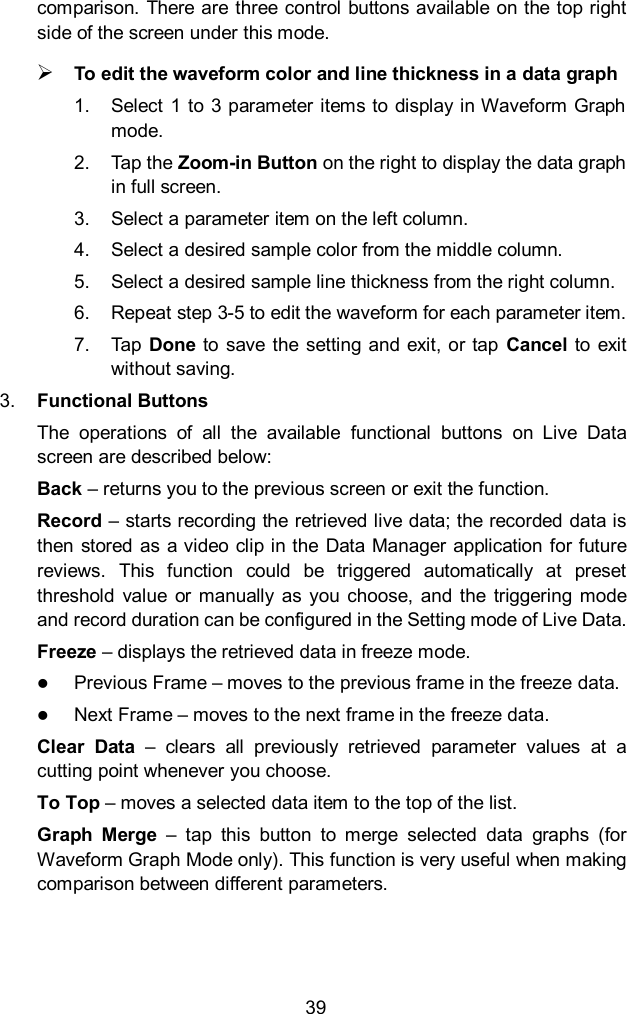
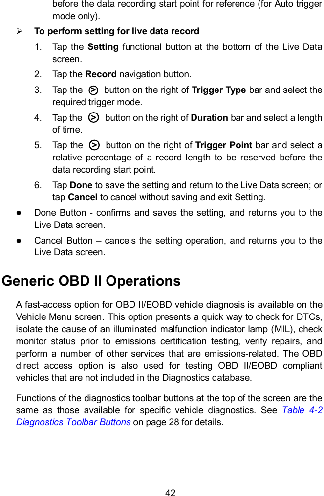
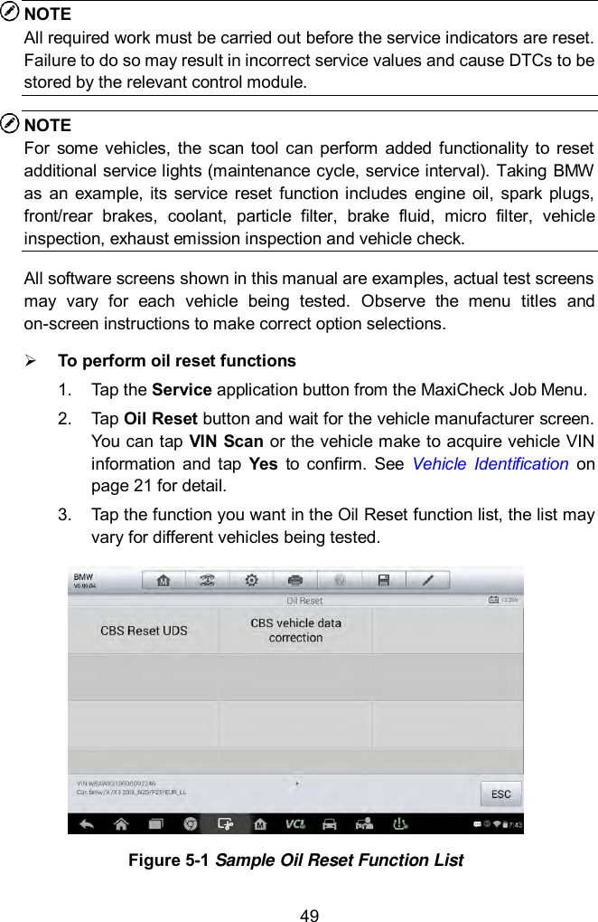
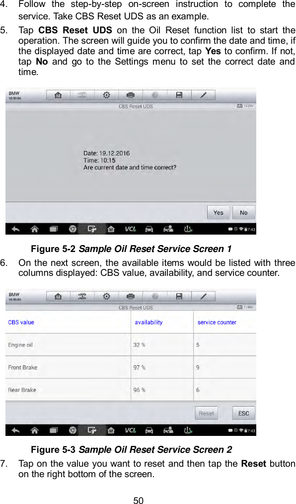
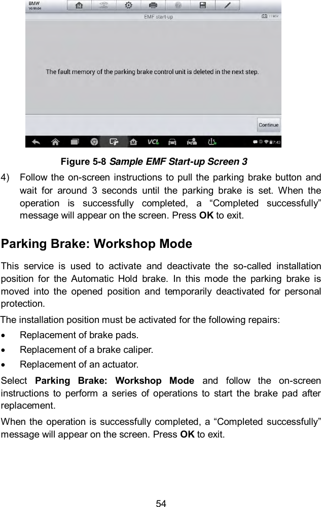
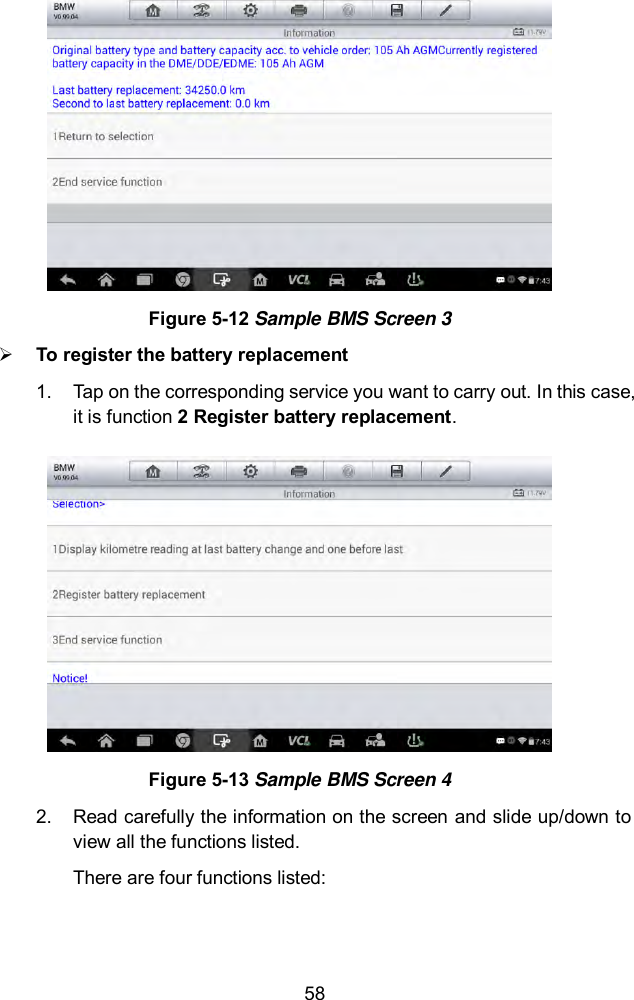

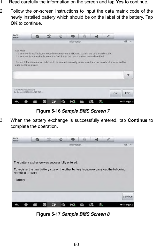
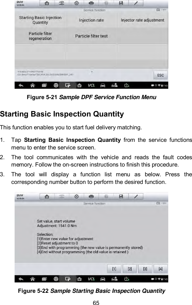
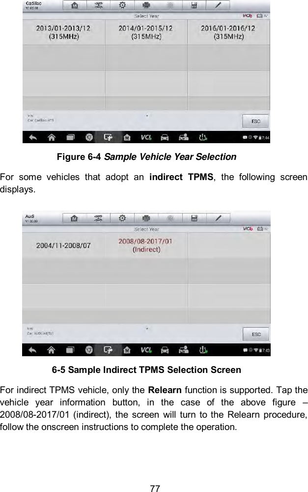
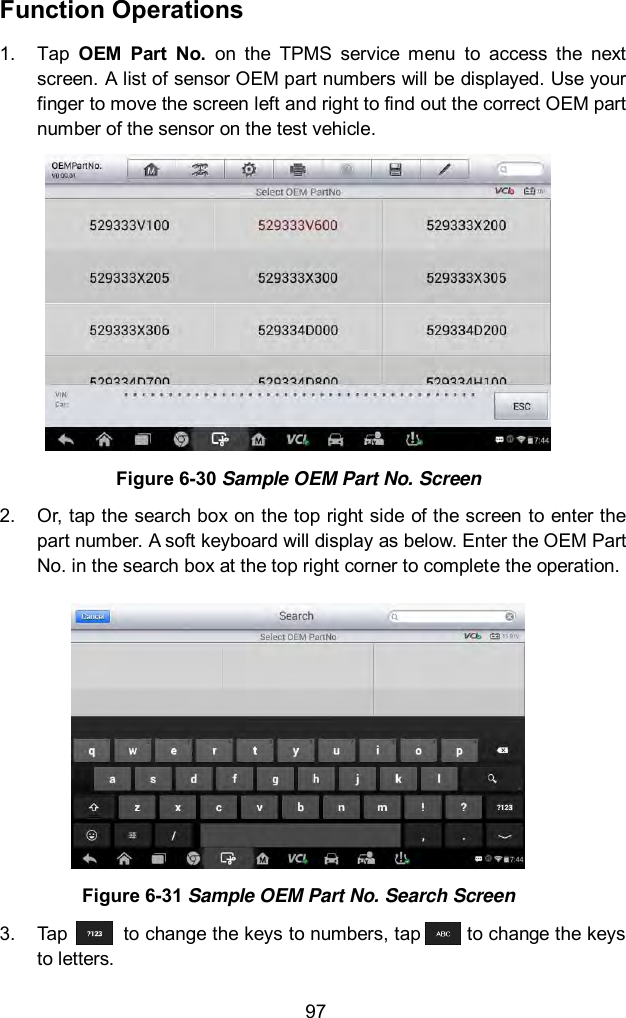
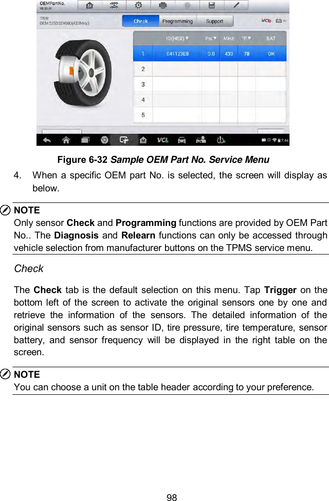
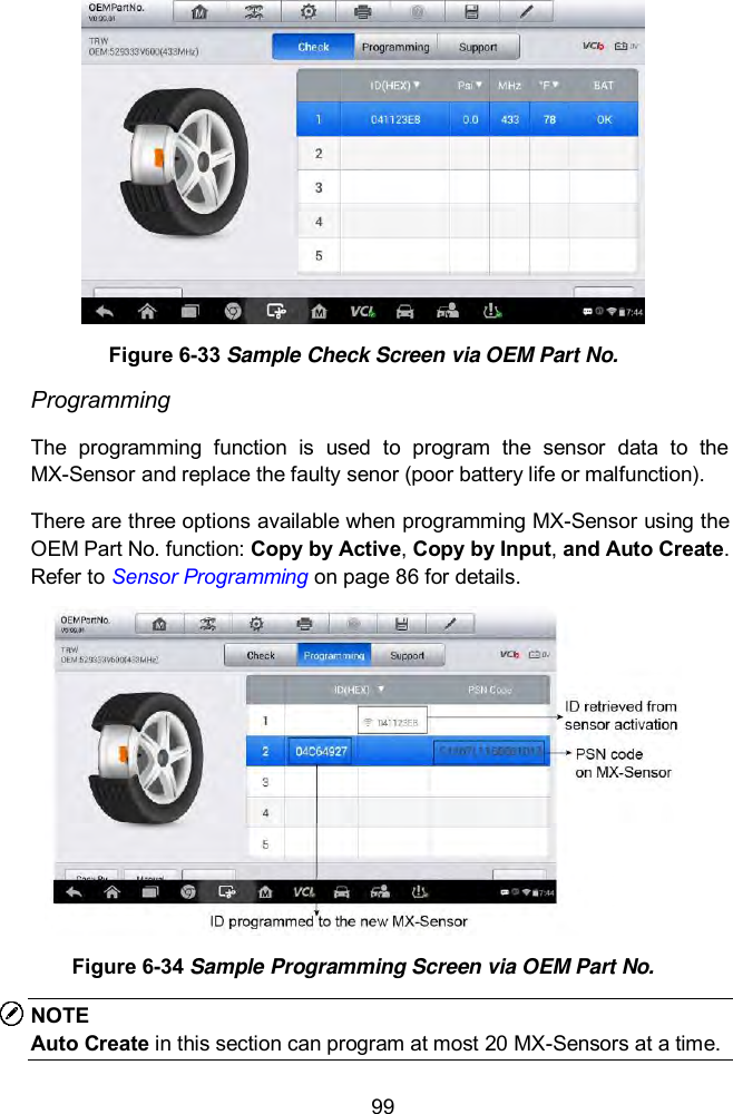
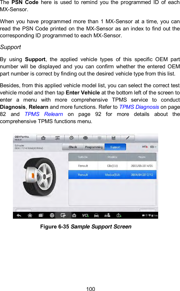
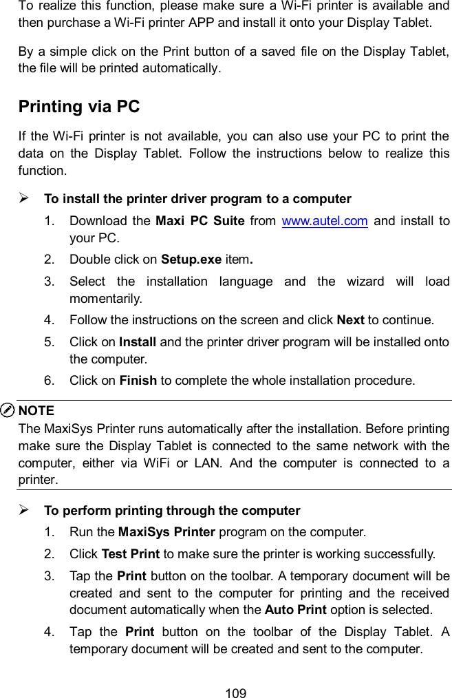
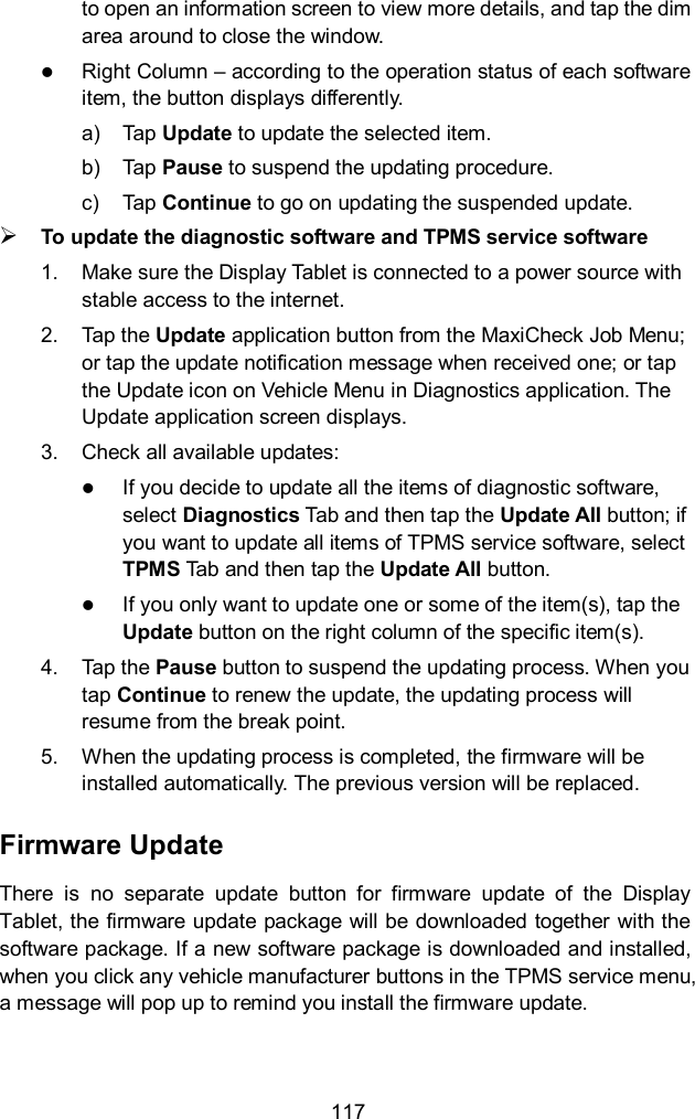
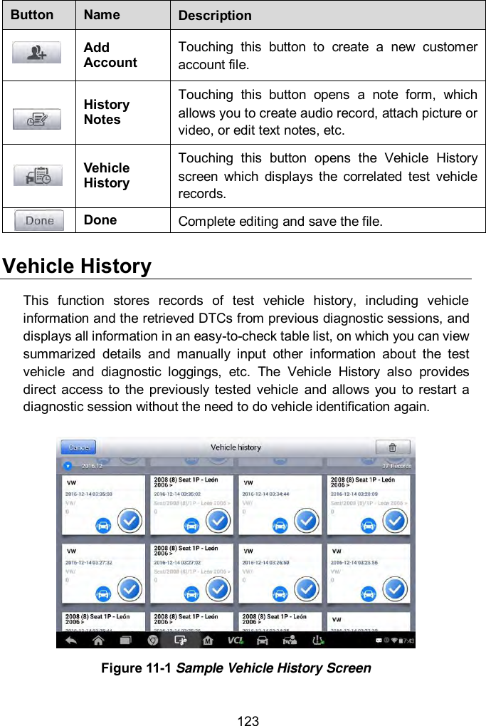
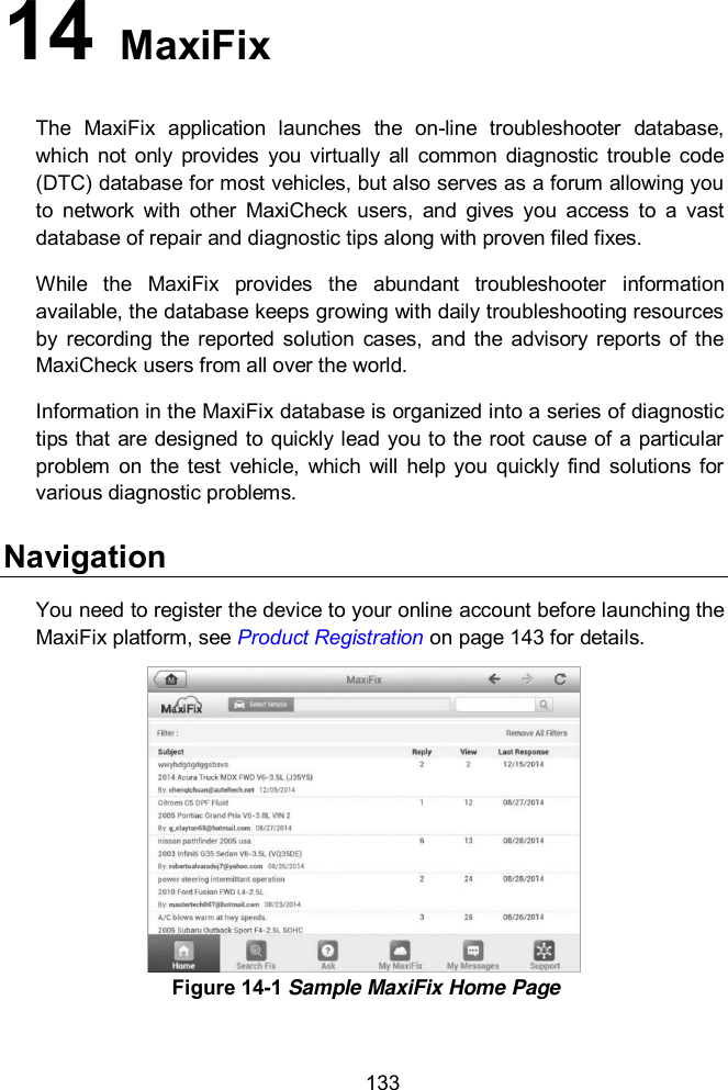
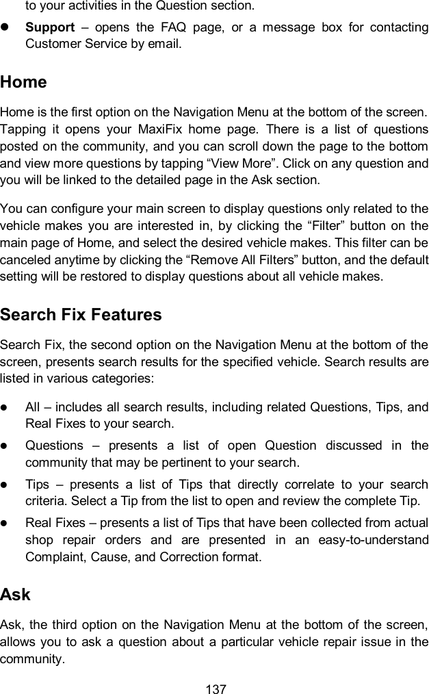
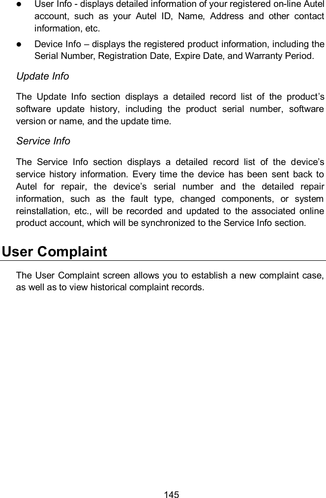
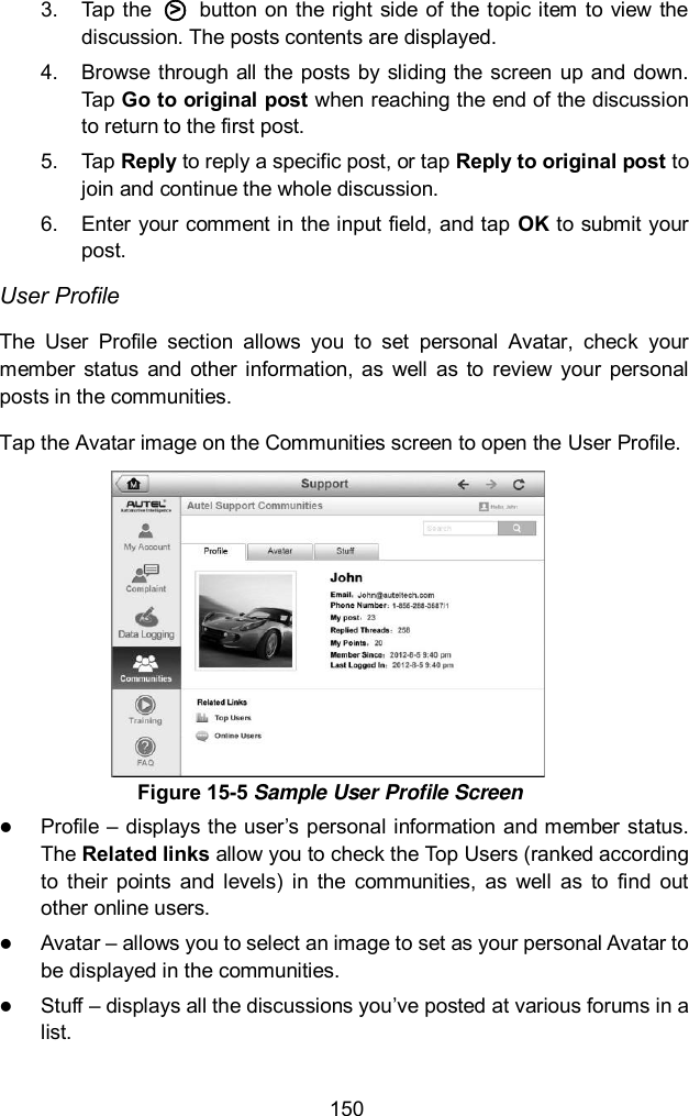
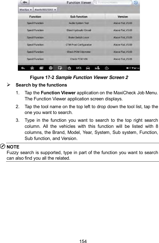
![66 [1] Enter New Value for Adjustment From the Starting Basic Inspection Quantity menu, tap [1] and the screen displays as below. Figure 5-23 Sample Enter New Value Screen After entering the value, tap OK to save the value to the tool. Tap ESC to exit the operation. NOTE The data you input should be in the range given. If the input data is out of range, the tool will display a warning message “Permissible adjustment range exceeded.” [2] Reset Adjustment to 0 Once the [2] is tapped, the tool will automatically reset the value to zero. [3]/[4] Store Data and Exit When the fuel delivery rate adjustment is completed, tap [3] to store the new value in the control units; or select [4] and OK to retain the old value. Injection Rate This function is used to adjust the injection volume. 1. Tap Injection Rate from the service functions menu to enter the service screen.](https://usermanual.wiki/Autel-Intelligent-Tech/MX808-TPMS.Users-Manual/User-Guide-3318777-Page-73.png)
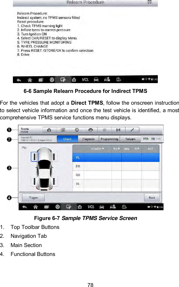
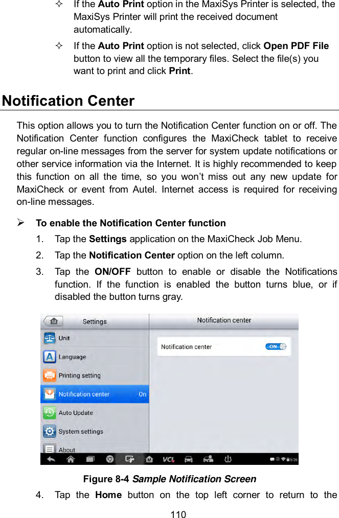
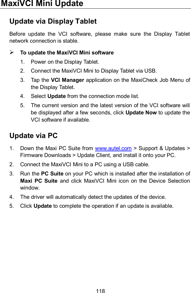
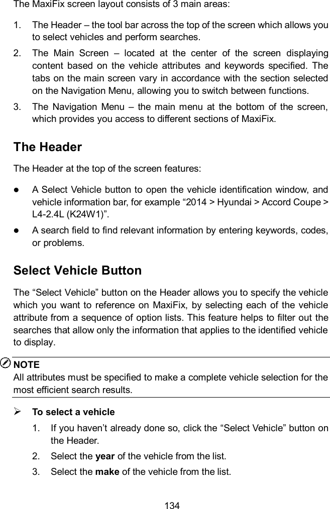
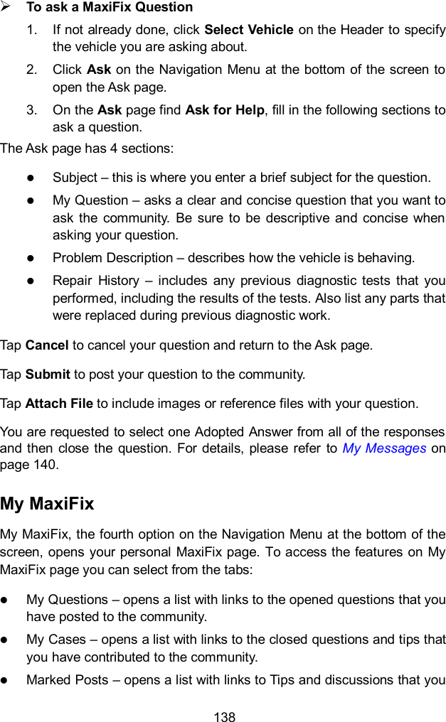
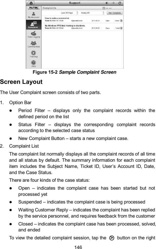
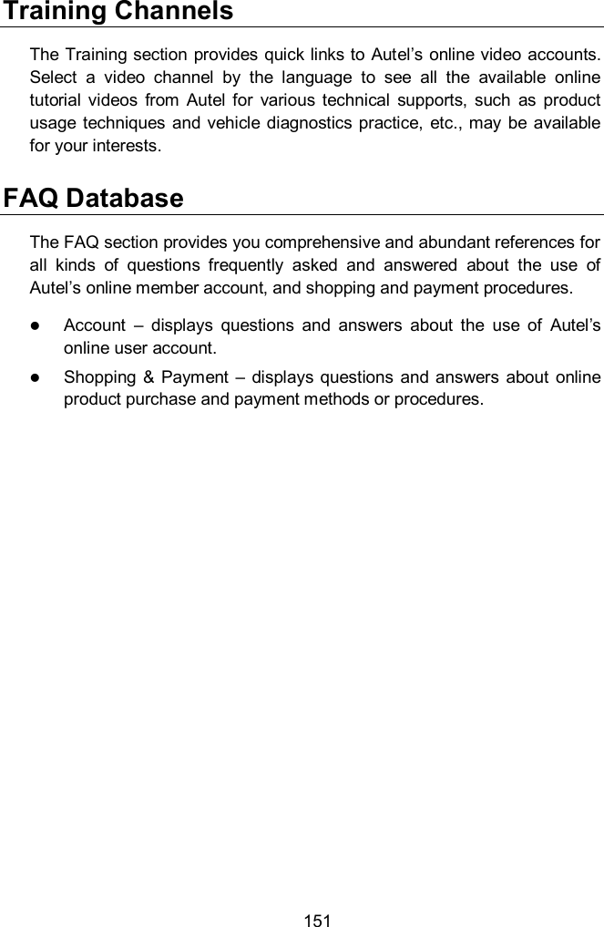
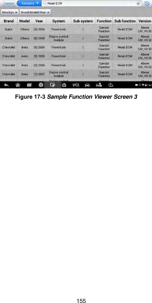
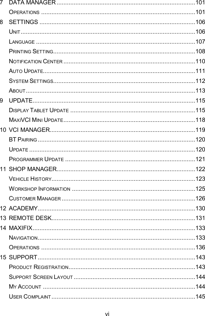
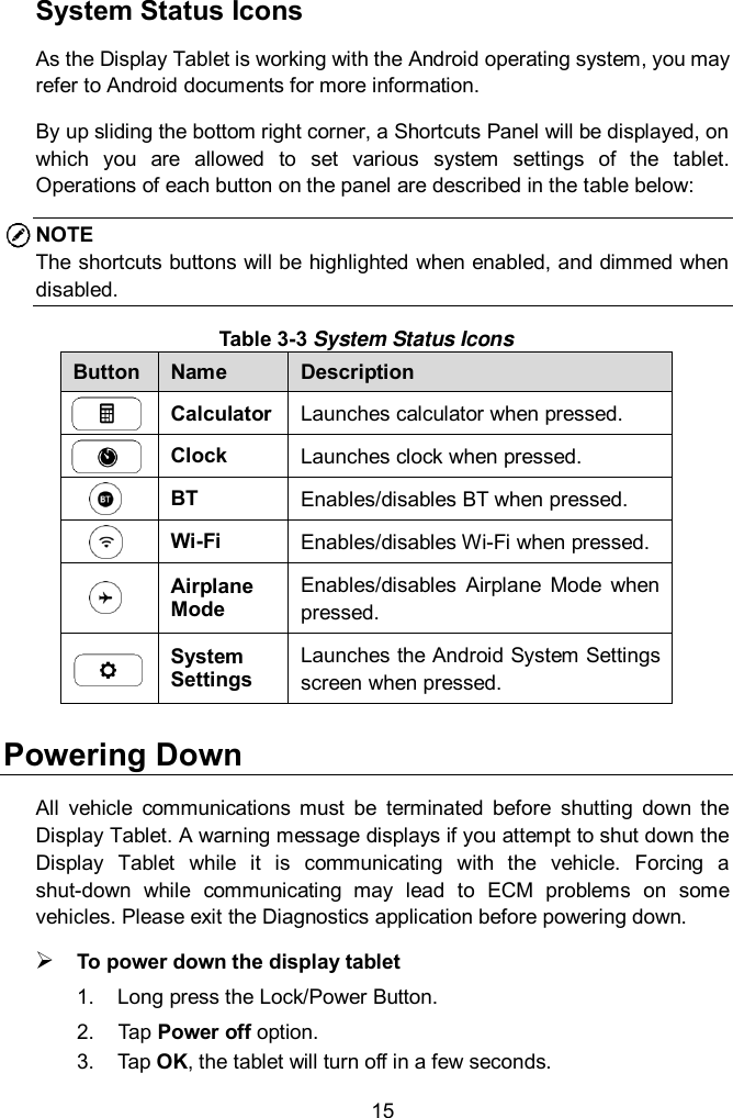
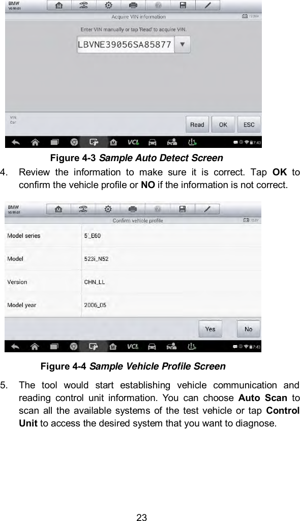
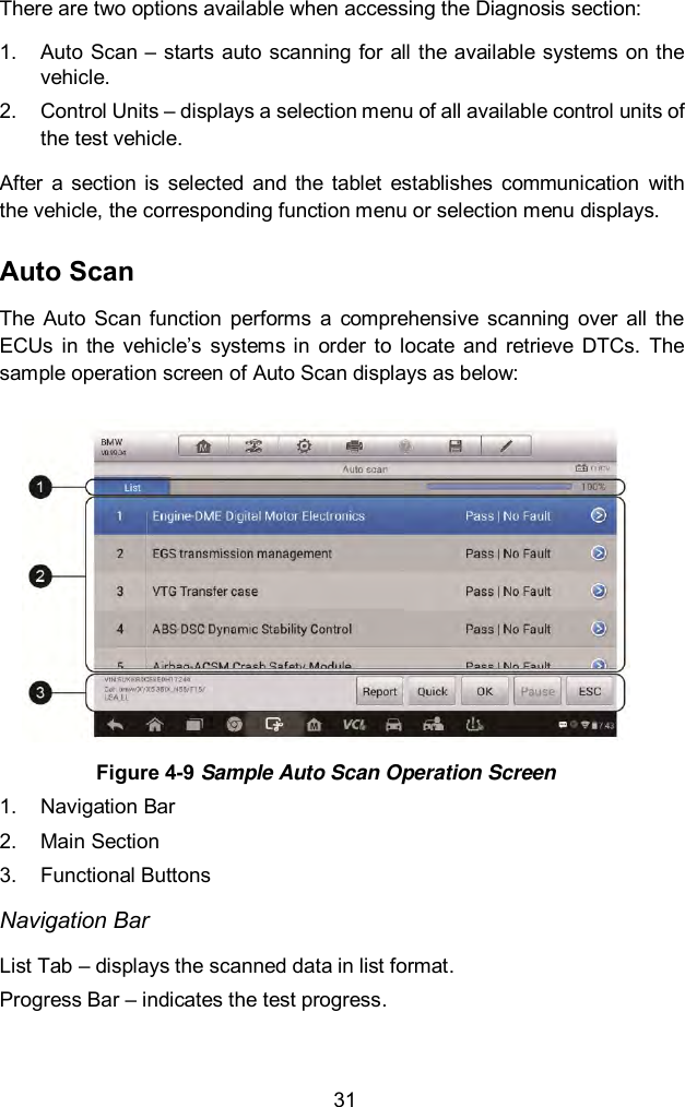
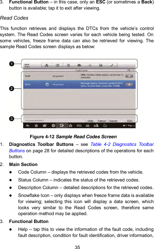
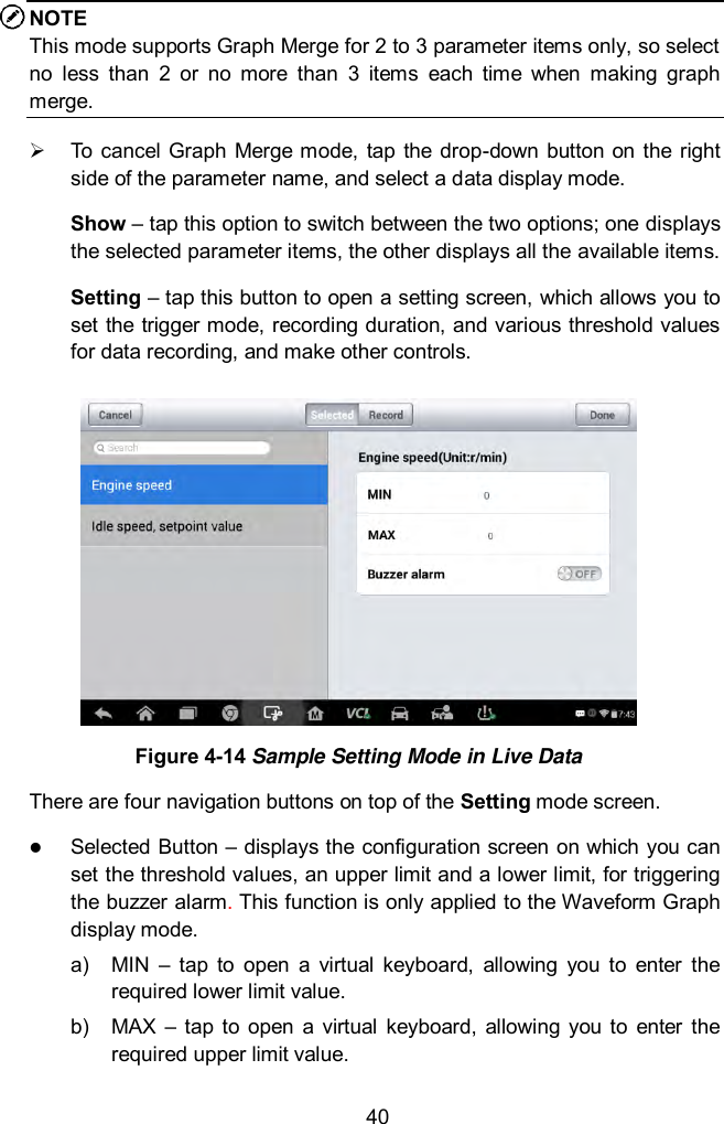
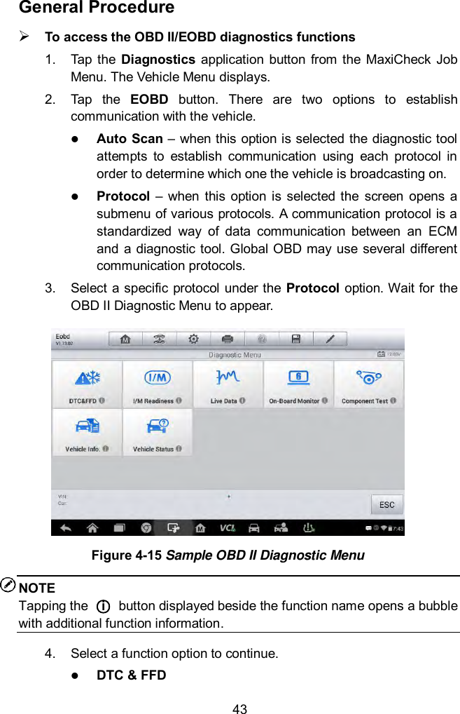
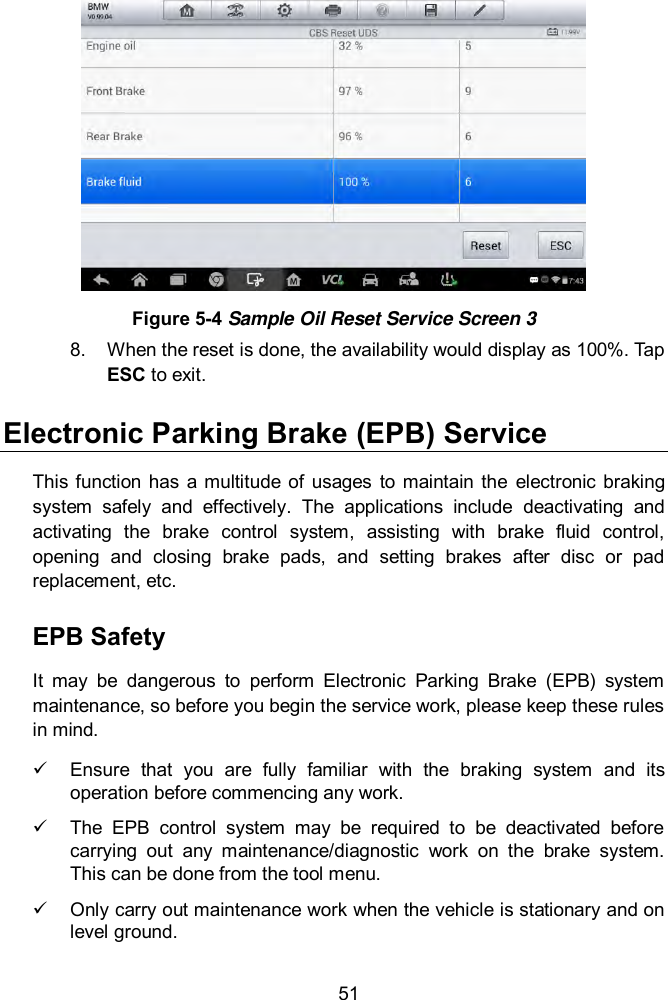
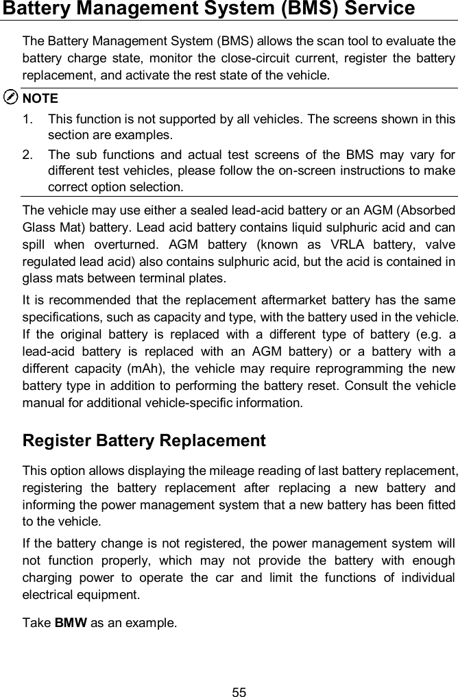
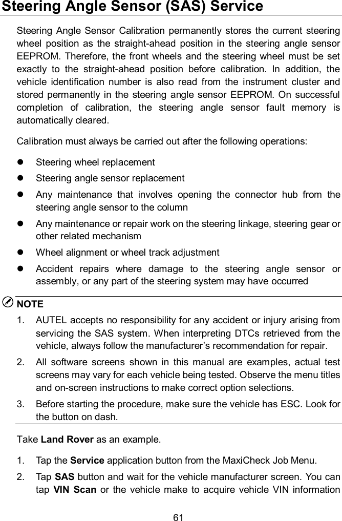
![67 2. The tool communicates with the vehicle and reads the fault codes memory. Follow the on-screen instructions to finish this procedure. 3. Then the tool will display as below. Press the corresponding number button to perform the desired function. Figure 5-24 Sample Injection Rate Screen [1] Enter New Value for Adjustment From the Injection Rate menu, tap [1] and the screen displays as below. Figure 5-25 Sample Enter Value Screen](https://usermanual.wiki/Autel-Intelligent-Tech/MX808-TPMS.Users-Manual/User-Guide-3318777-Page-74.png)
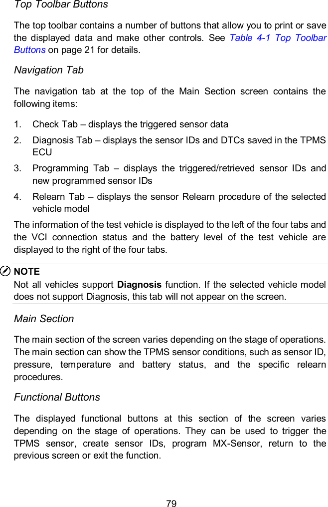
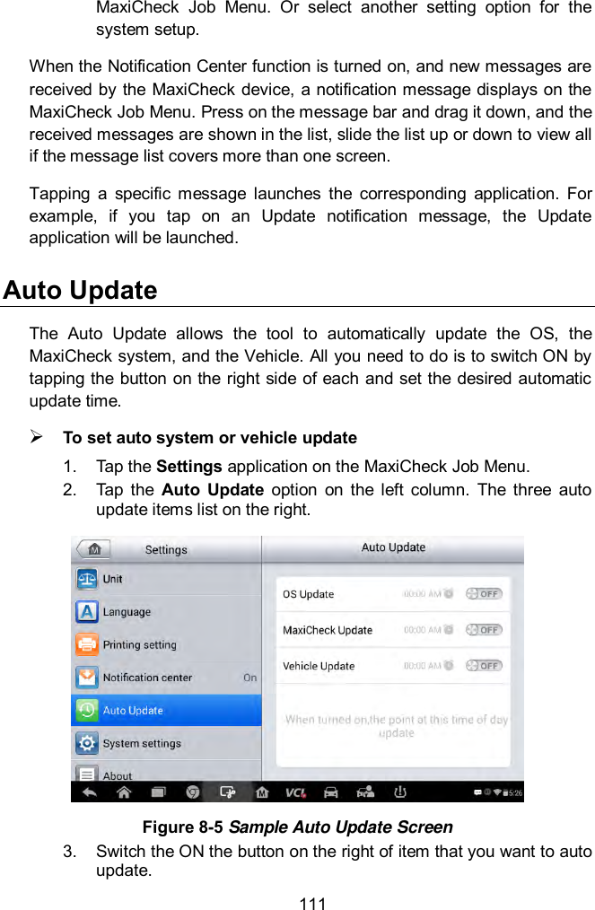
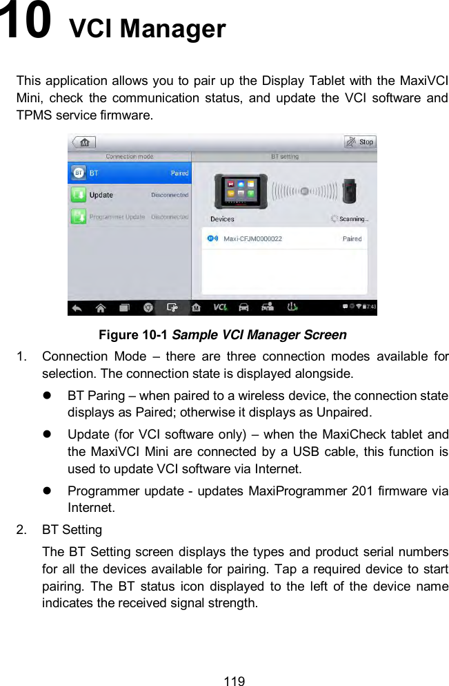
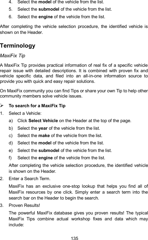
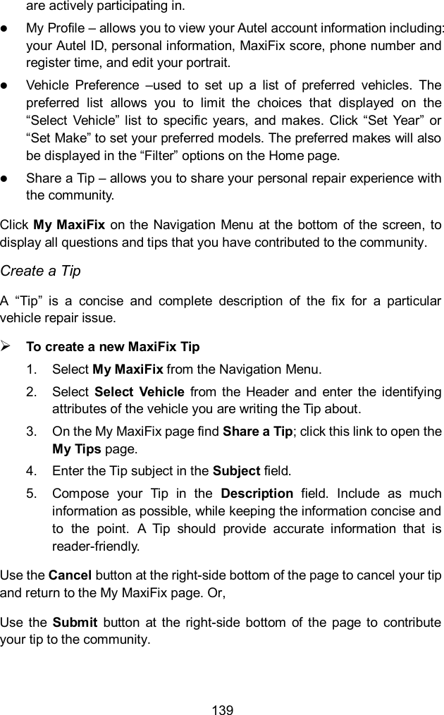
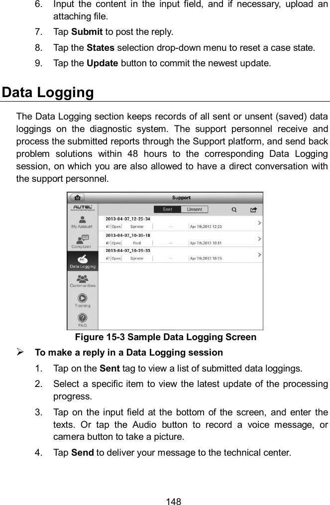
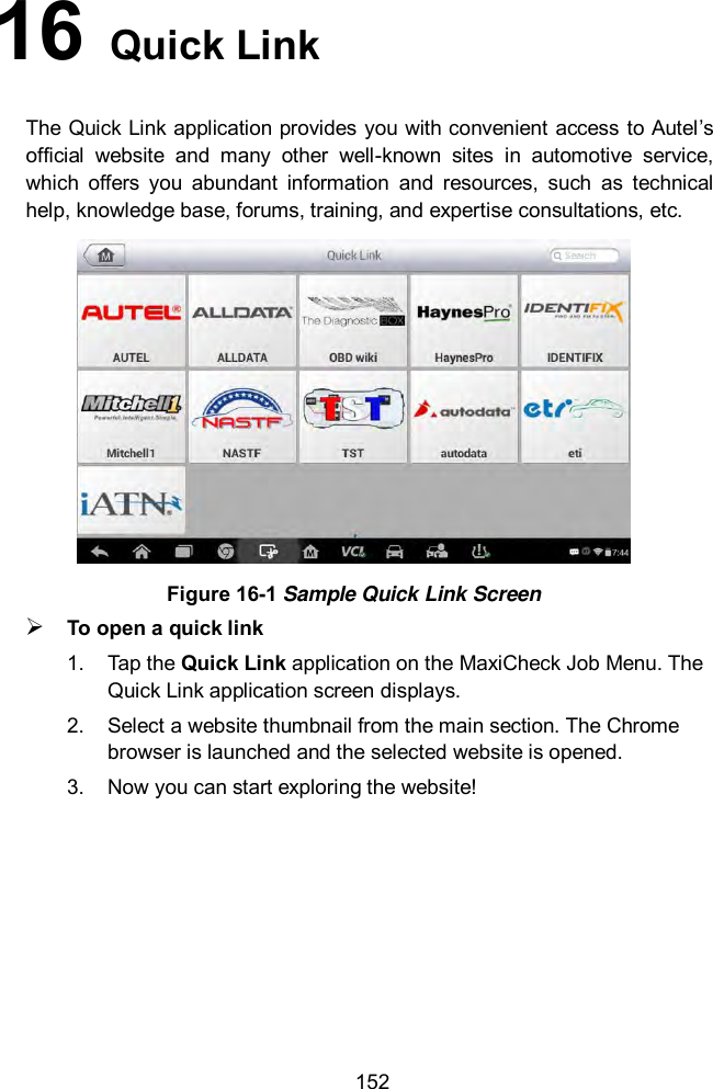
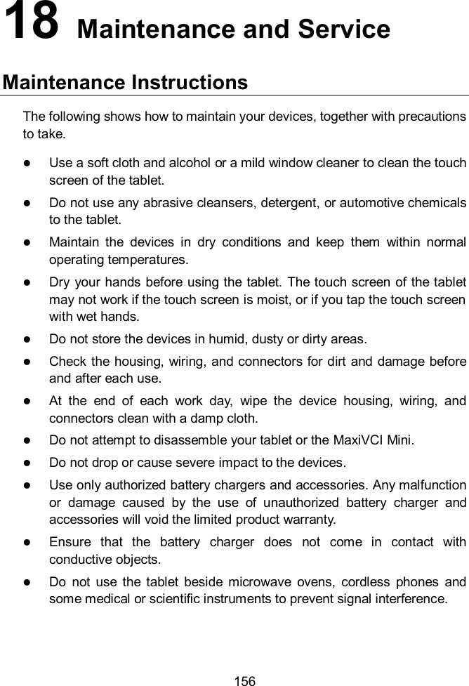
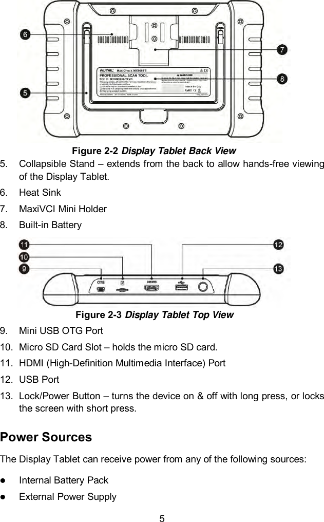
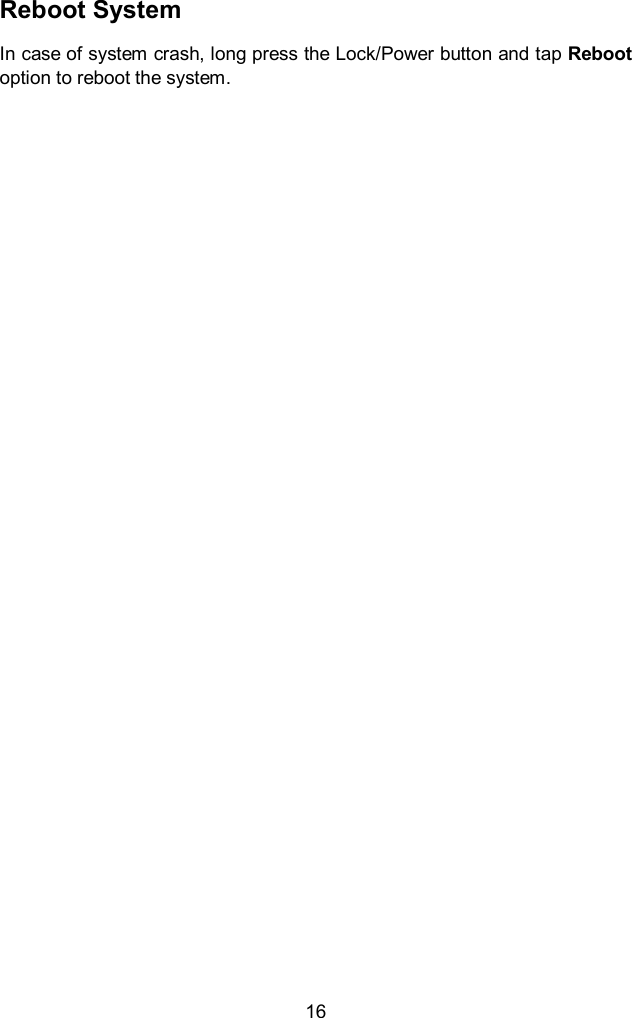
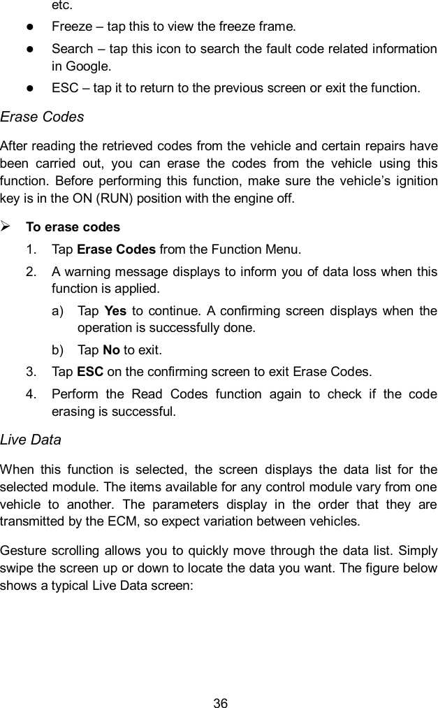
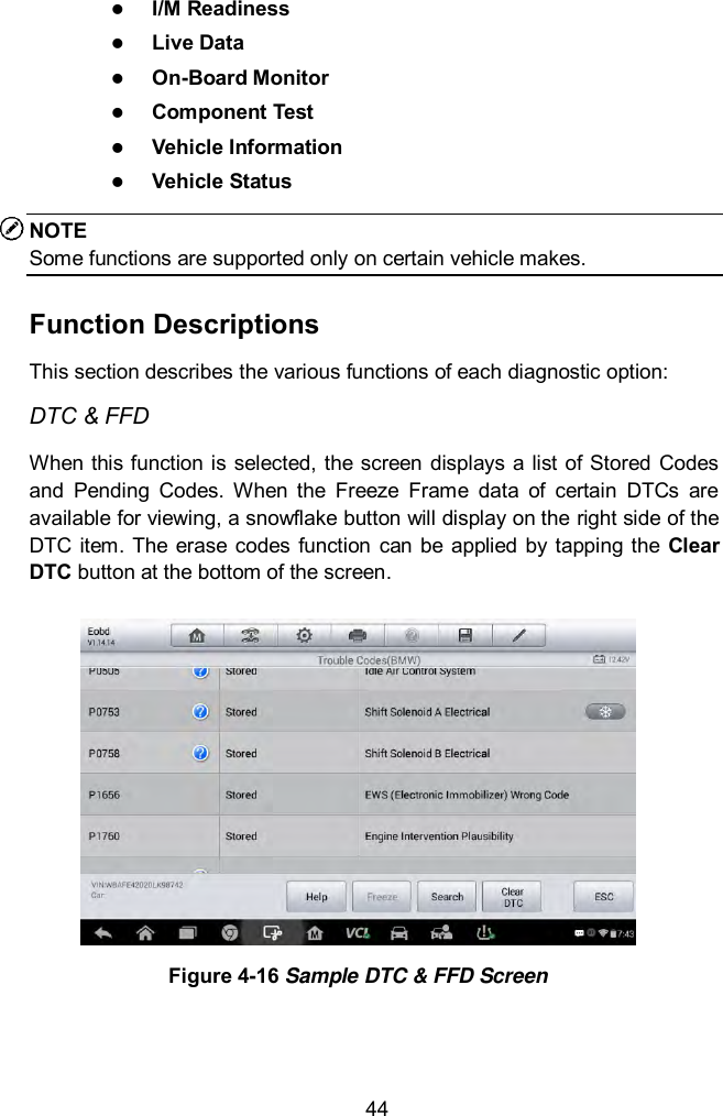
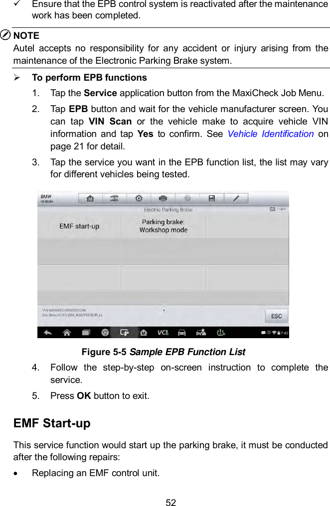
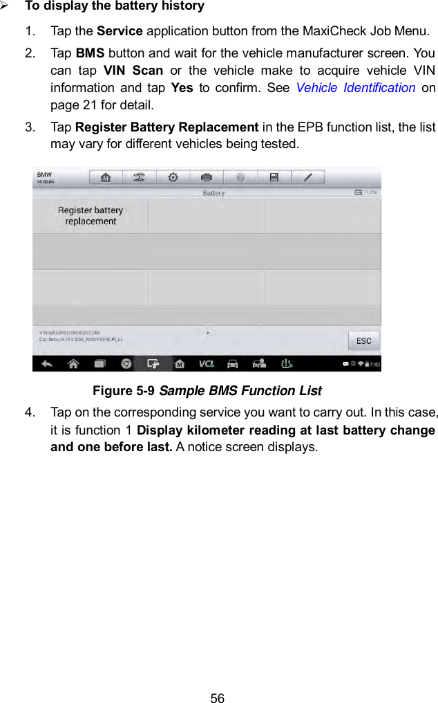
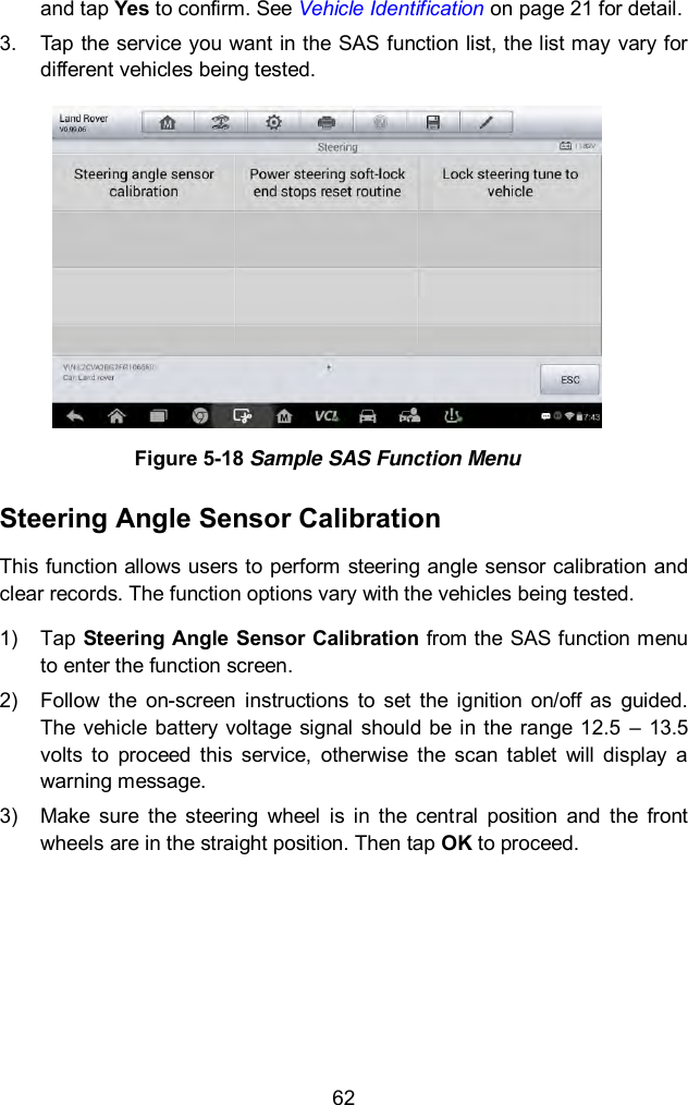
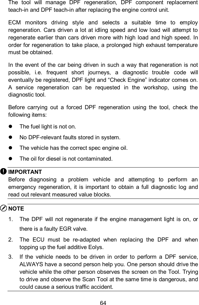
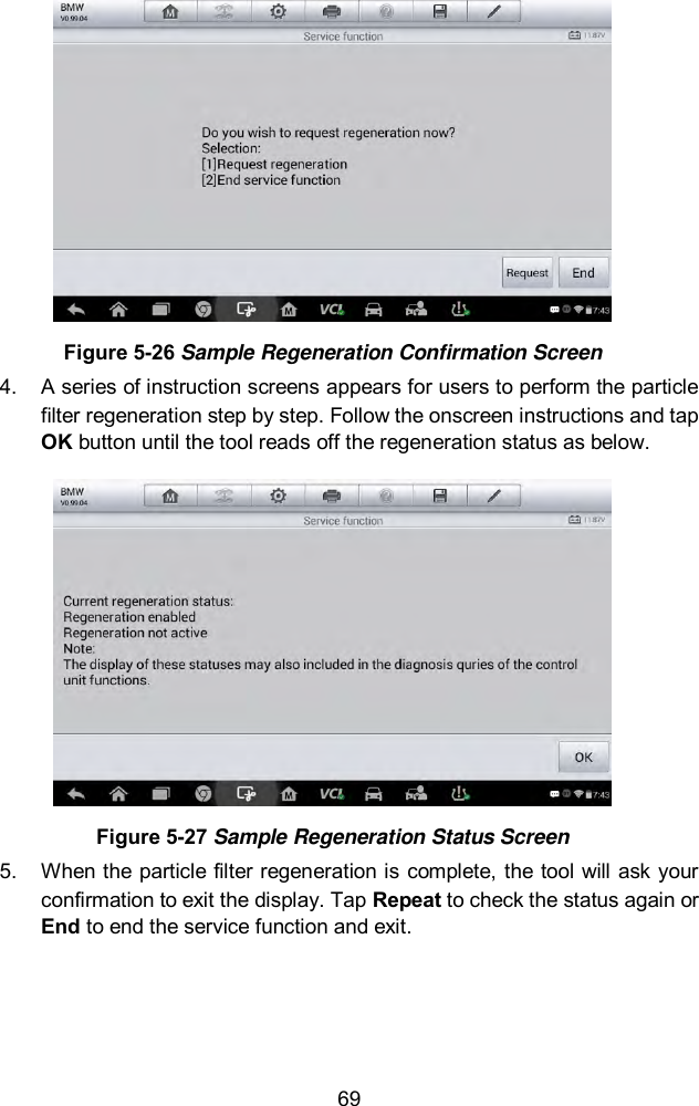
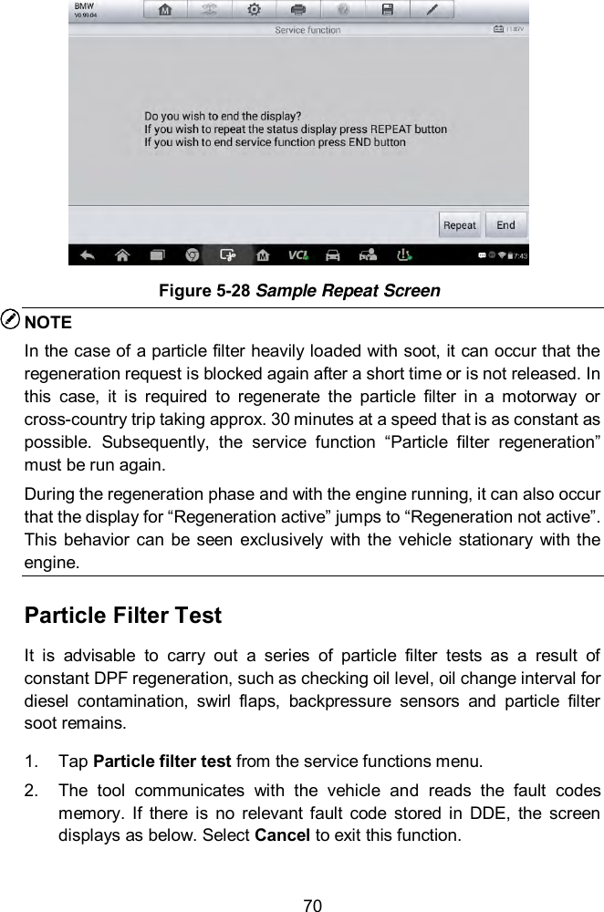
![68 NOTE The data you input should be in the reasonable range. If the input data is out of range, the tool will display a warning message “Permissible adjustment range exceeded.” [2] Reset Adjustment to 100% Once the [2] is pressed, the tool will automatically reset the value to 100%. [3]/[4] Store Data and Exit When the injection volume adjustment is completed, select [3] and OK to store the new value in the control units; or select [4] and OK to retain the old value. Injector Rate Adjustment This function is used to adjust the injector rate for individual cylinders. 1. Tap Injection rate adjustment from the service functions menu. 2. The tool communicates with the vehicle and reads the fault codes memory. Follow the on-screen instructions to enter the service function. 3. Tap the corresponding number button to enter new value for each cylinder. 4. Follow the on-screen instructions to tap on the corresponding number [1] [2] [3] [4] to enter the new value for the cylinder, restore the old value, and exit after finish the function. Particle Filter Regeneration This function is used to perform the particle filter regeneration. 1. Tap Particle filter regeneration from the service functions menu. 2. The tool communicates with the vehicle and reads the fault codes memory. Follow the on-screen instructions to check the prerequisites before particle filter regeneration, such as the fuel, the time and driving style. 3. If every prerequisite is met, the tool will ask your confirmation to proceed as below. Tap Request to begin a regeneration or End to end the service function and exit.](https://usermanual.wiki/Autel-Intelligent-Tech/MX808-TPMS.Users-Manual/User-Guide-3318777-Page-75.png)
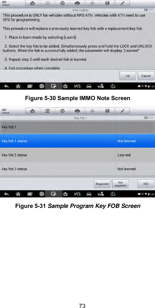
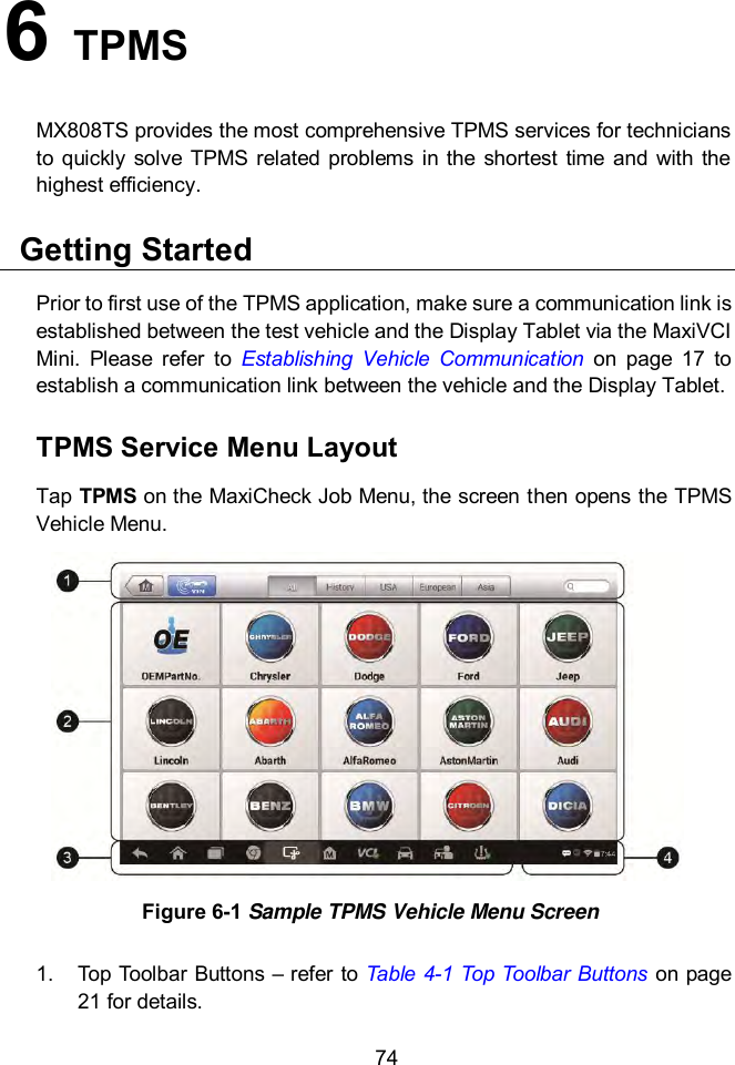
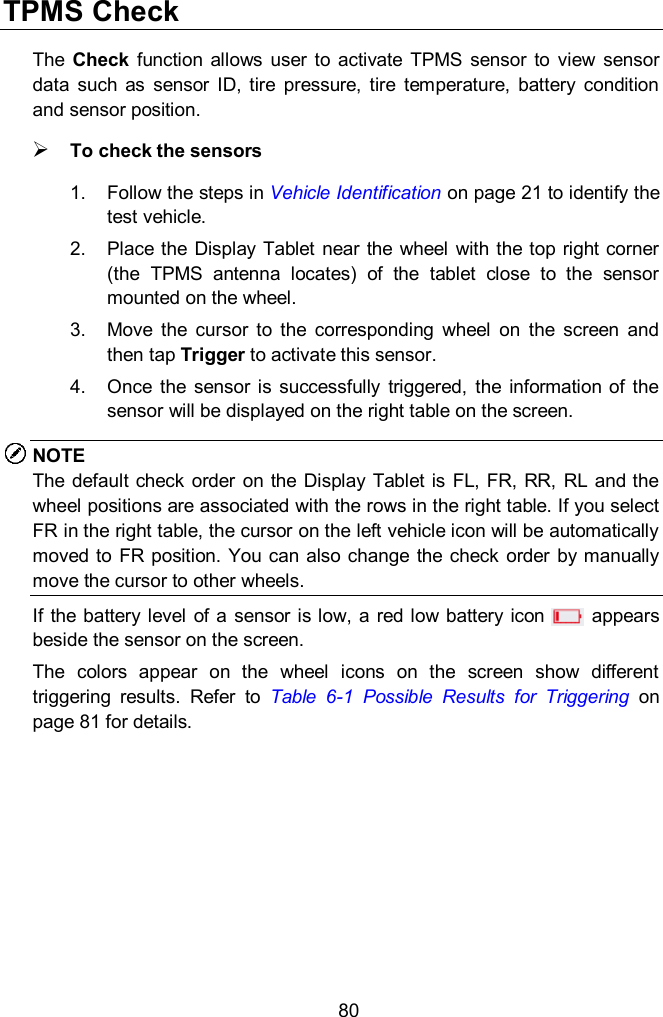
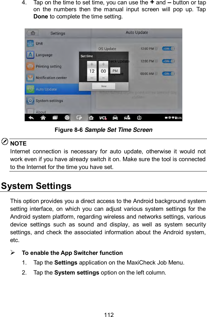
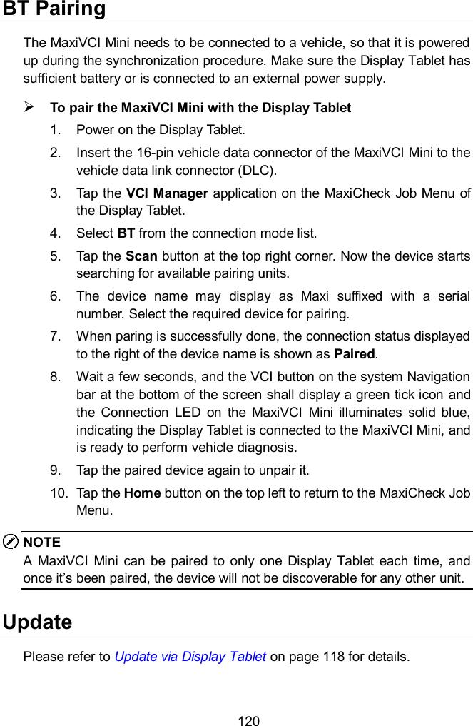
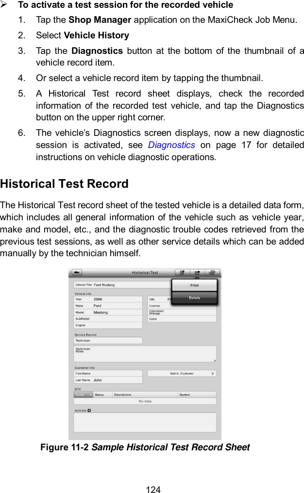
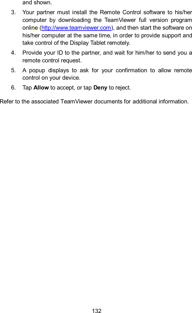
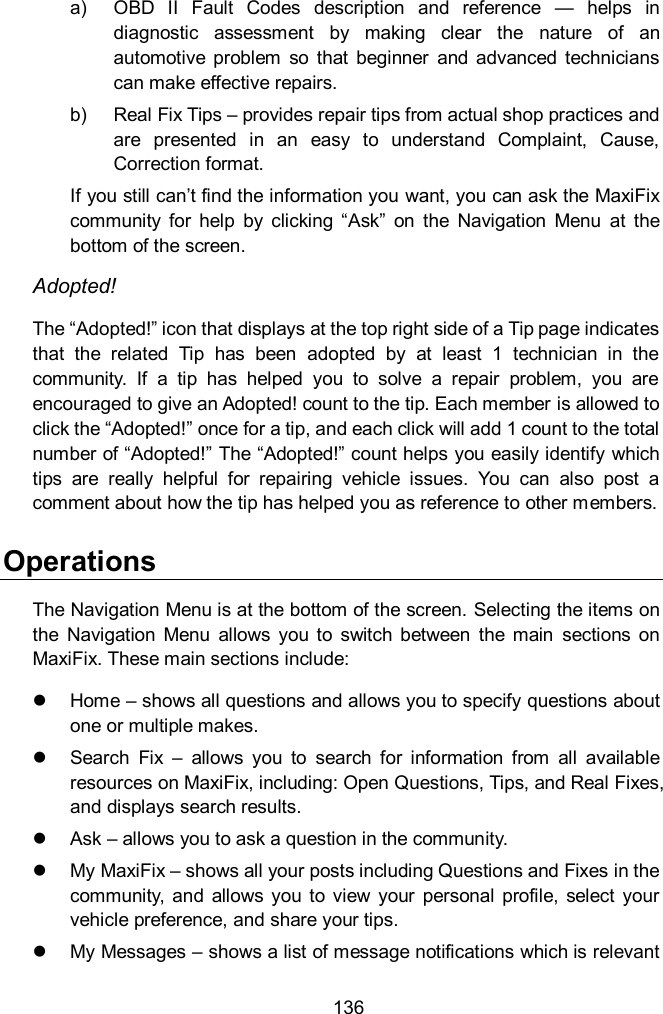
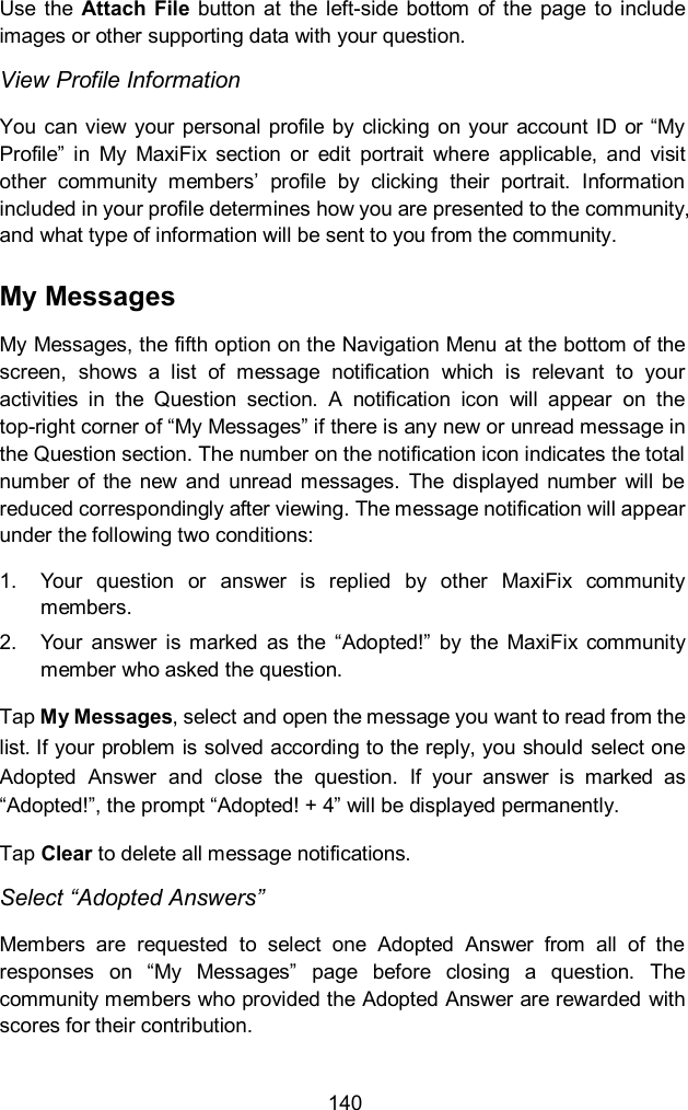
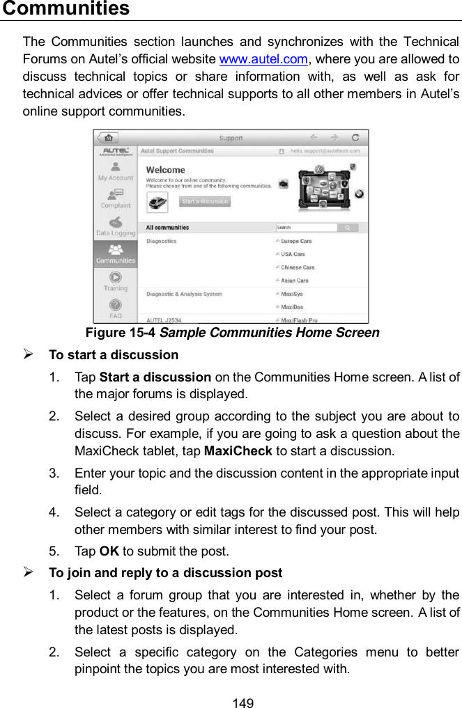
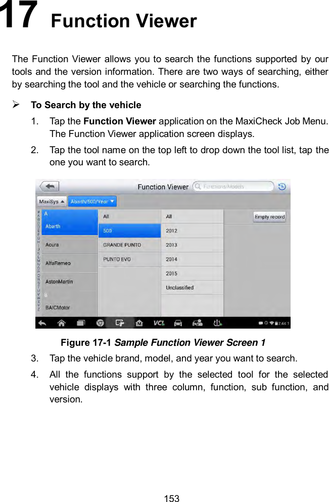
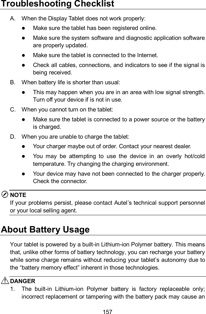
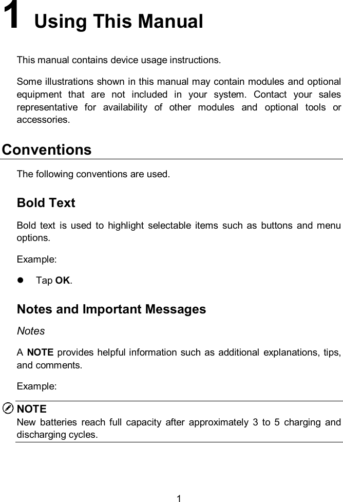
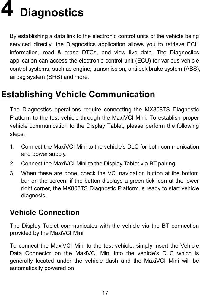
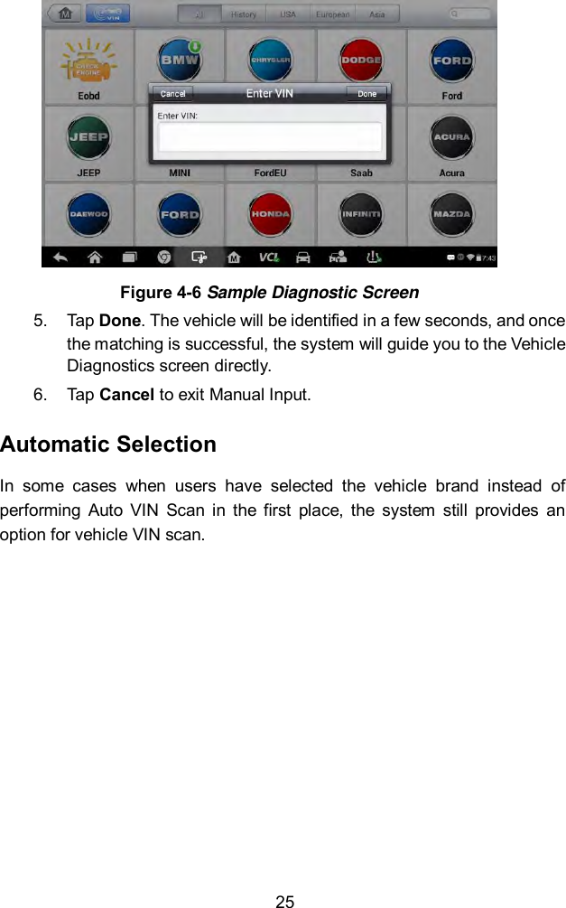
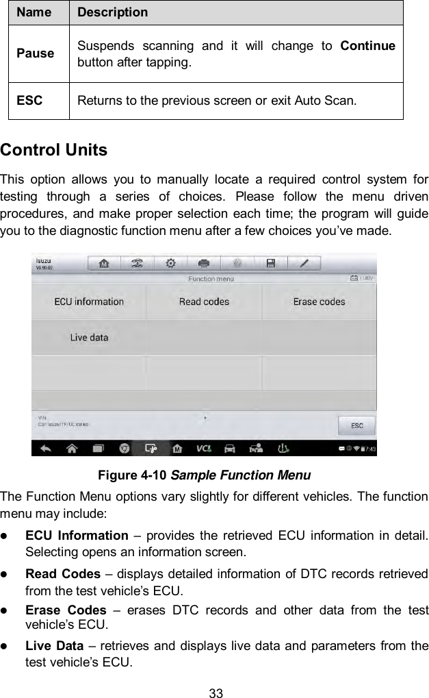
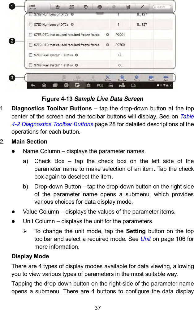
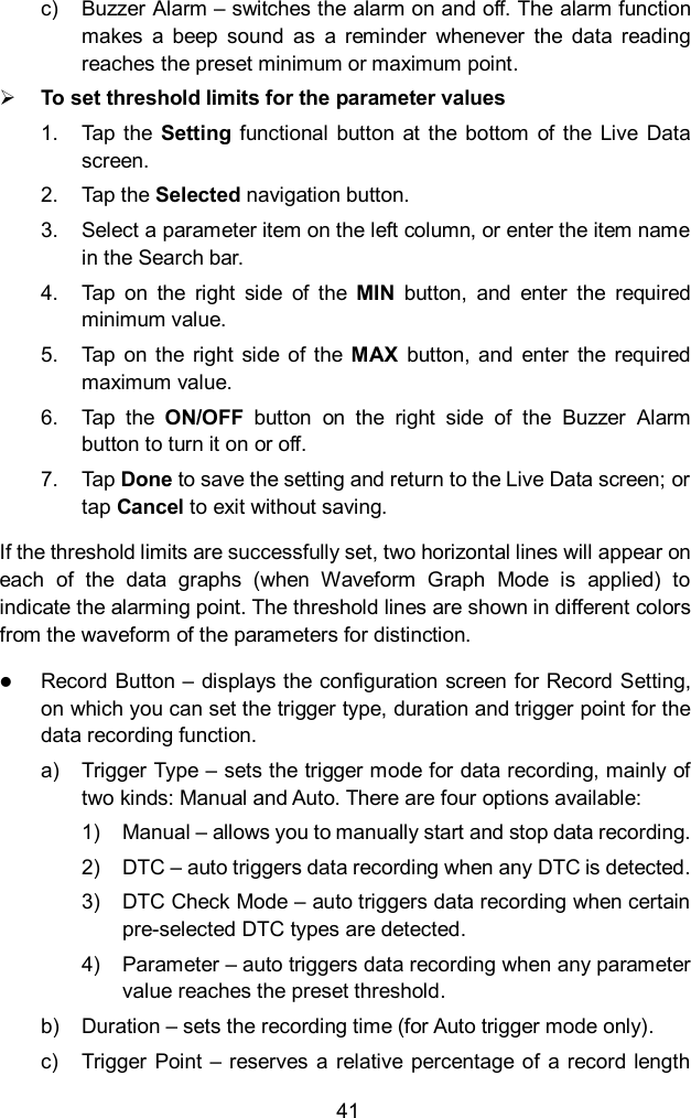
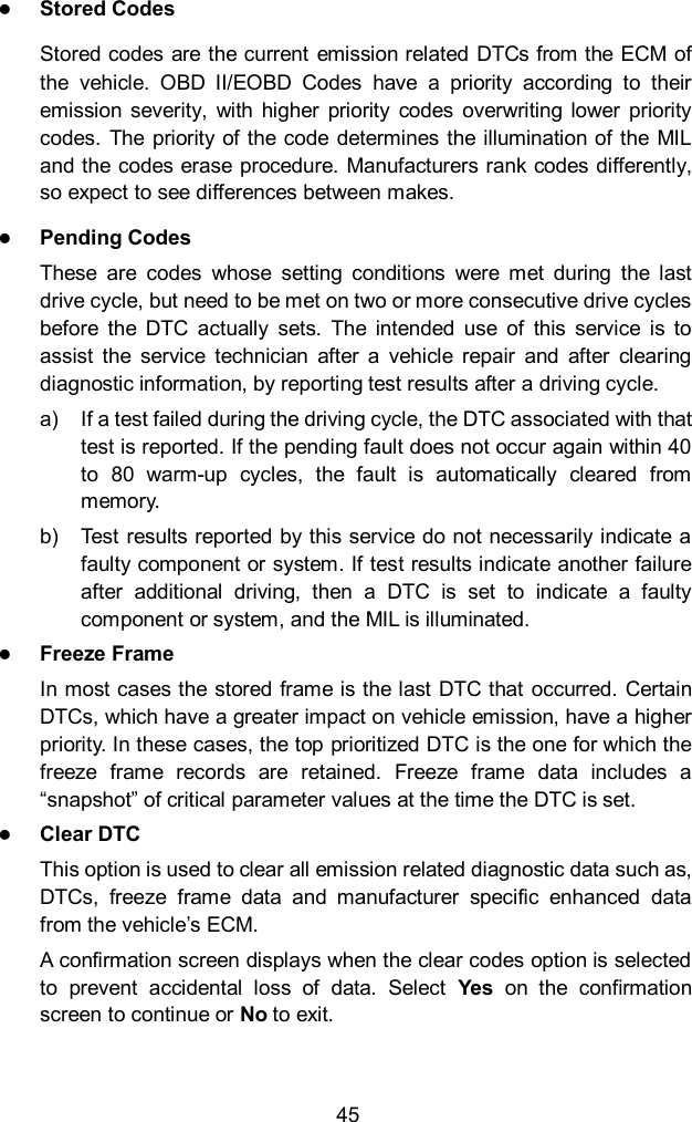
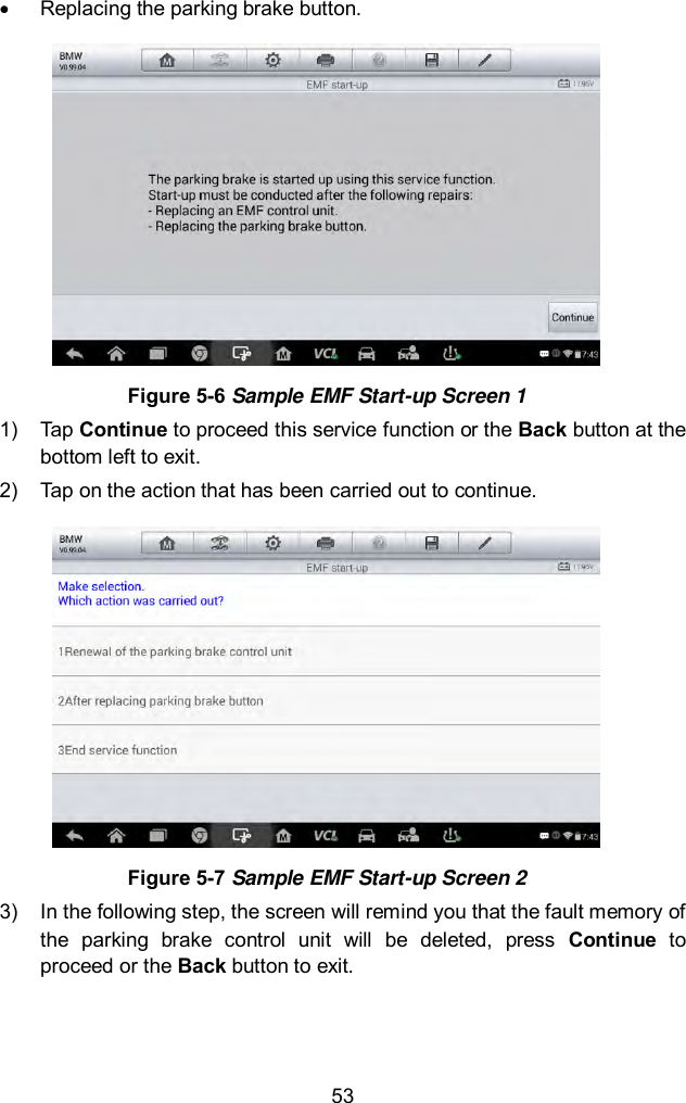
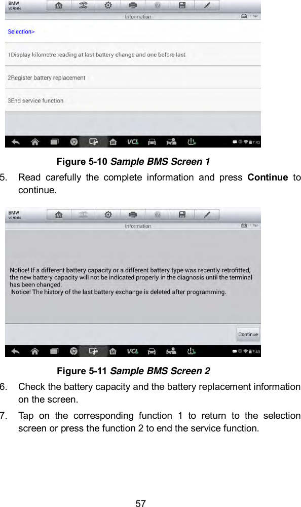
![71 3. If there are DPF-related codes stored in DDE, the screen displays as below. Select OK to continue or Cancel to exit this function. Figure 5-29 Sample Codes Screen 4. The tool shows a list of particle filter test. Select the corresponding number button to perform the desired test [1] [2] [3] [4] [5]. [1] Visual Inspection of Engine Oil [2] Visual Inspection of Particulate Filter [3] Function Check or Swirl Flaps [4] Exhaust Backpressure Test [5] Actual/Target Value Check-Mass Air Flow Sensor Immobilizer (IMMO) Service An immobilizer is an anti-theft mechanism that prevents an automobile’s engine from starting unless the correct ignition key or other device is present. This device prevents thieves from starting the car by a method known as hot wiring. Most new vehicles have an immobilizer as standard equipment. An important advantage of this system is that it doesn’t require the car owner to activate it; it operates automatically. An immobilizer is considered as providing much more effective anti-theft protection than an audible alarm alone; many auto insurance companies offer lower rates for vehicles that are equipped with them.](https://usermanual.wiki/Autel-Intelligent-Tech/MX808-TPMS.Users-Manual/User-Guide-3318777-Page-78.png)