Autel Intelligent Tech MXVCIMINI Wireless Diagnostic Interface User Manual
Autel Intelligent Tech. Corp., Ltd. Wireless Diagnostic Interface Users Manual
Users Manual

Contents
GENERAL NOTICE ........................................................................................... 1
INTRODUCTION ................................................................................................ 2
WIRELESS COMMUNICATION ................................................................................... 3
USB CONNECTIVITY .............................................................................................. 3
POWER SOURCE ................................................................................................... 3
FUNCTIONAL DESCRIPTION ........................................................................... 4
STATUS LEDS ..................................................................................................... 5
VEHICLE DATA CONNECTOR ................................................................................... 6
USB PORT .......................................................................................................... 6
TECHNICAL SPECIFICATIONS................................................................................... 6
CAPABILITIES ....................................................................................................... 7
PRODUCT TROUBLESHOOTING ..................................................................... 8
VEHICLE LINKING ERROR ....................................................................................... 8
PC COMMUNICATION ERROR .................................................................................. 8
DRIVER SETUP ................................................................................................. 9
FIRMWARE UPDATE ...................................................................................... 12
UPDATE ONLINE ................................................................................................. 12
COMPLIANCE INFORMATION ........................................................................ 14
WARRANTY AND SERVICE ............................................................................ 16
LIMITED ONE YEAR WARRANTY ............................................................................ 16
SERVICE INFORMATION ........................................................................................ 16

1
General Notice
The wireless diagnostic interface MaxiVCI Mini has been carefully
designed and tested to comply with OBD II protocols. However, some
vehicle models are not in full compliance with these protocols for various
reasons. In addition, the computer control systems or sensors on any
given vehicle may be malfunctioning.
While Autel’s testing and the experiences of the users have shown the
unit to be safe and reliable, there is an inherent risk in using any product
that may potentially affect the operation or drive-ability of your vehicle.
If you are concerned about the operation of your vehicle at any time
while using the MaxiVCI Mini:
Pull off the roadway immediately or as soon as it is safe to do so.
Disconnect the device from the OBD II port.
Consult a licensed mechanic or automobile service center.
Contact your local distributor, or visit www.autel.com for issues or
concerns about the product. We maintain an active database of the
feedback we received, and your comments can help us continuously
improve the product.
2
Introduction
The wireless diagnostic interface MaxiVCI Mini is a small interface box
used to connect to a vehicle’s diagnostic connector (DLC) and connect
wirelessly with some Autel Diagnostic Tools including MaxiCheck
MX808TS and MaxiTPMS TS608, as well as standalone PC, as a
vehicle communication interface (VCI) for vehicle data transmission.
Thanks to the wireless BT technology, with which you are allowed to
work freely around the vehicle.
The MaxiVCI Mini can communicate with vehicles’ electronic control
units (ECUs), guaranteeing performance and speed that redefine multi-
brand diagnostics. The development of this interface has been focused
on reducing the communication time and ensuring the tool is practical to
use.
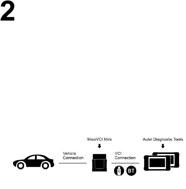
Figure 2-1 MaxiVCI Mini Communication Platform
The MaxiVCI Mini Communication Platform combines the MaxiVCI Mini
and the display tablet with technical information into a single program,
ensuring quick and simple access to the vehicle to perform
comprehensive diagnostics applications.

3
Wireless Communication
The MaxiVCI Mini supports BT communication. It can transmit vehicle
data to some Autel Diagnostic Tools including MaxiCheck MX808TS
and MaxiTPMS TS608 without a physical connection. The working
range of the transmitter through BT communication is about 33 feet
(about 10 m). A signal lost due to moving out of range automatically
restores itself when the display unit is brought closer to the MaxiVCI Mini
unit.
USB Connectivity
The MaxiVCI Mini also provides a direct connection to some Autel
Diagnostic Tools including MaxiCheck MX808TS and MaxiTPMS TS608
or a PC via a USB 2.0 full-speed connection. All of the electronics are
contained in the device shell, making it a compact and rugged vehicle
communication tool.
Power Source
The MaxiVCI Mini operates on 12-volt vehicle power, which it receives
through the vehicle data connection port. The unit powers on whenever
it is connected to an OBD II/EOBD compliant data link connector (DLC).
It can also be powered through connection with a PC via the USB cable,
so there’s no need to connect the device to the vehicle when performing
firmware update through the PC.
4
Functional Description
The MaxiVCI Mini device package includes the unit, user manual, and a
CD with driver program and update agent.
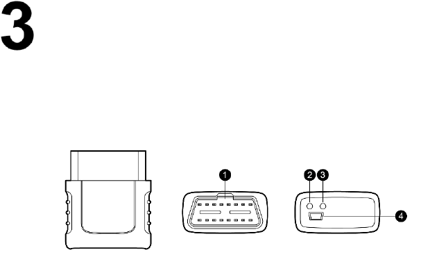
Figure 3-1 Product View
1. Vehicle Data Connector (16-Pin)
2. Power LED:The power LED illuminates solid green when the
device is power up and operates normally, it will illuminate solid red
if the device is not operating normally;
3. Connection LED:The connection LED illuminates solid green when
the device is successfully connected via USB cable but no
communication with the vehicle, it flashes green when the device is
successfully connected via USB cable and there is communication
with the vehicle; the connection LED illuminates solid blue when
the device is successfully connected via BT but no communication
with the vehicle, it flashes blue when the device is successfully
connected via BT and there is communication with the vehicle.
4. USB Port

5
Status LEDs
There are 2 status LEDs on the front panel of the MaxiVCI Mini, which
indicates its working status as well as the hardware conditions, and are
very useful for troubleshooting the device’s communication or
connection to the vehicle, display tablet and/or the PC. See table 3-1 for
detailed description of the status LEDs.
Table 3-1 Status LEDs on the Front Panel
LED
Color
Description
Power
Green
Illuminates solid green when
powered on.
Red
Flashes red when system failure
occurs.
Note: The power LED illuminates
red automatically every time
when the device is powered up,
which is a normal self-test
procedure, and it will turn green
automatically later when the
device starts working normally.
Connection
Green
Illuminates solid green when
properly connected with the
display tablet or the PC via the
USB cable
Blue
Illuminates solid blue when
connected with the display tablet
via wireless (BT) connection

6
Vehicle Data Connector
The vehicle connector connects the MaxiVCI Mini to the vehicle’s 16-pin
DLC directly.
USB Port
The USB port provides the easiest connection between the device and
the display tablet or the PC via a USB cable, and is used to control the
device from the software application running on the PC.
Technical Specifications
Table 3-2 Specifications
Item
Description
Communications
BT V.2.1 + EDR
USB 2.0
Wireless Frequency
2.4 GHz
Input Voltage Range
12 VDC
Supply Current
150 mA @ 12 VDC
Operating Temperature
0°C to 50°C (ambient)
Storage Temperature
-20°C to 70°C (ambient)
Dimensions (L x W x H)
47 mm (1.7”) x 23 mm (0.9”)
x 51 mm (2.0”)
Weight
33.1g (0.07 lb.)

7
Capabilities
When used in conjunction with the display table or the OEM softwares
from the PC, the MaxiVCI Mini is able to perform the following functions:
Auto diagnostics to read and clear the error memory, to display
system parameters and the status of the ECU;
Activation, adjustments and configurations that are essential for
ensuring a complete repair;
Resetting the service lights or the airbag systems;
Configuration of the ECUs, keys and remote controls, etc.

8
Product Troubleshooting
This part describes problems that you may encounter while using the
MaxiVCI Mini.
Vehicle Linking Error
A communication error occurs if the MaxiVCI Mini fails to communicate
with the vehicle’s control module when performing diagnostic
procedures. You need to do the following check-ups:
Verify that the ignition is ON.
Check if the device’s vehicle data connector is securely connected
to the vehicle’s DLC.
Turn the ignition off and wait for about 10 seconds. Turn the ignition
back to on and continue the operation.
Verify the control module is not defective.
PC Communication Error
Verify the interface device is powered, and the power LED is
illuminated green.
Check if there is any firewall software interfering with the
connection port.
Check if the green status light is illuminated for USB communication.
If these issues have been addressed, verified, and you are still
having trouble, please contact technical supports for assistance.

9
Driver Setup
In order for the MaxiVCI Mini to operate correctly with the diagnostic
applications on the PC, you will need to first install the device’s driver
onto the PC that controls the device.
The program package requires Windows XP, Windows 7 (32 or 64 bit),
Windows 8 (32 or 64 bit), or Windows 10 (32 or 64 bit).
IMPORTANT
Do not plug the MaxiVCI Mini onto the PC until you have installed the
driver program.
The following steps may vary depending on the operating system or
components that are installed on your computer, but in general this is
the standard installation process.
1. Insert the included CD into the CD/DVD slot of the PC and open
the CD folder.
2. Double click on “Autel Run.exe” item.
3. Click the MaxiVCI Mini icon in the MaxiSys PC Suite screen.
4. Select the installation language and the driver installation wizard
will load momentarily.
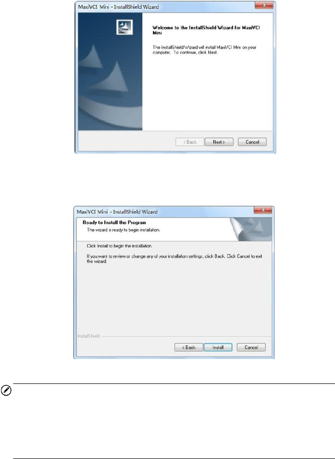
5. Follow the wizard instructions on the screen and click “Next” to
continue.
10
Figure 5-1 Sample Installation Step 1
6. Click on “Install” and the driver program will be installed onto your
PC.
Figure 5-2 Sample Installation Step 2
NOTE
During this part of the process a MS-DOS style window may pop up and
may remain on your screen for a short while, which is perfectly normal.
Do not attempt to close the MS-DOS style window manually as this will
prevent the device driver being installed successfully. It will close
automatically when the device driver installation is complete.
11
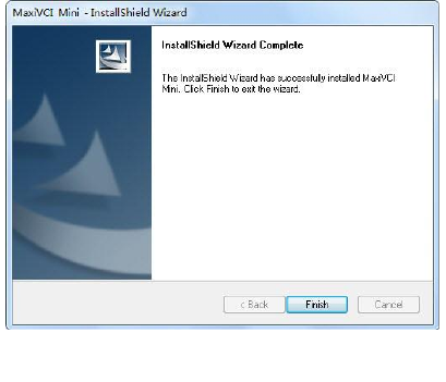
7. When the driver is successfully installed, a confirm window will
appear. Click on “Finish” to complete the whole installation
procedure.
Figure 5-3 Sample Installation Step 3

12
Firmware Update
Autel periodically releases updates to the device’s drivers. Updates are
necessary to solve specific problems and to ensure the VCI device is
working properly with the OEM software. If you are experiencing any
problems during use, always make sure that you have the latest device
software and drivers.
Update Online
This function allows you to update the driver software for the device
through the PC. Make sure the PC is connected to the Internet before
using this function.
1. Connect the MaxiVCI Mini to the PC via the USB cable.
2. Verify the Power and Connection LEDs on the front panel are
illuminated green.
3. From Windows Start Menu, find and double click the “MaxiVCI Mini”
icon, wait for the program interface to pop up.
4. The update agent will automatically check for the available update
online.
5. Press the “Next” button to install the newest firmware.
6. Press the “Cancel” button to exit.
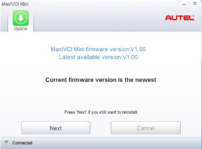
13
Figure 6-1 Sample Online Update Window

14
Compliance Information
FCC COMPLIANCE FCC ID: WQ8-MXVCIMINI
This device complies with Part 15 of the FCC Rules.
Operation is subject to the following two conditions:
1 This device may not cause harmful interference.
2 This device must accept any interference received, including
interference that may cause undesired operation.
WARNING
Changes or modifications not expressly approved by the party
responsible for compliance could void the user's authority to operate the
equipment.
NOTE
This equipment has been tested and found to comply with the limits for
a Class B digital device, pursuant to Part 15 of the FCC Rules. These
limits are designed to provide reasonable protection against harmful
interference in a residential installation.
This equipment generates uses and can radiate radio frequency energy
and, if not installed and used in accordance with the instructions, may
cause harmful interference to radio communications. However, there is
no guarantee that interference will not occur in a particular installation.
If this equipment does cause harmful interference to radio or television
reception, which can be determined by turning the equipment off and on,
the user is encouraged to try to correct the interference by one or more
of the following measures: ⅰ. Reorient or relocate the receiving
antenna. ⅱ. Increase the separation between the equipment and
receiver. ⅲ. Connect the equipment into an outlet on a circuit different
from that to which the receiver is connected. ⅳ. Consult the dealer or
an experienced radio/TV technician for help.
15
FCC Radiation Exposure Statement:
This equipment complies with FCC radiation exposure limits set forth for
an uncontrolled environment.
RoHS COMPLIANCE
This device is declared to be in compliance with the European RoHS
Directive 2011/65/EU.
CE COMPLIANCE
This product is declared to conform to the essential requirements of the
following Directives and carries the CE mark accordingly:
EMC Directive 2014/30/EU
RED Directive 2014/53/EU
Low Voltage Directive 2014/35/EU

16
Warranty and Service
Limited One Year Warranty
Autel warrants to its customers that this product will be free from all
defects in materials and workmanship for a period of one (1) year from
the date of the original purchase, subject to the following terms and
conditions:
1) The sole responsibility of Autel under the Warranty is limited to
either the repair or, at the option of Autel, replacement of the device
at no charge with Proof of Purchase.
2) This warranty does not apply to damage due directly or indirectly,
to misuse, abuse, negligence or accidents, repairs or alterations
outside our Service Center or facilities, criminal activity, improper
installation, normal wear and tear, or to lack of maintenance.
3) Autel shall not be liable for any incidental or consequential
damages arising from the use, misuse, or mounting of the device.
Some states do not allow limitations on how long an implied
warranty lasts, so the above limitations may not apply to you.
4) All information in this manual is based on the latest information
available at the time of publication and no warranty can be made
for its accuracy or completeness. Autel reserves the right to make
changes at any time without notice.
Service Information
If you have any questions, please contact your local distributor or visit
our website at www.autel.com.
If it becomes necessary to return the tool for repair, contact your local
distributor for more information.
Notes: This product only use for professional person.