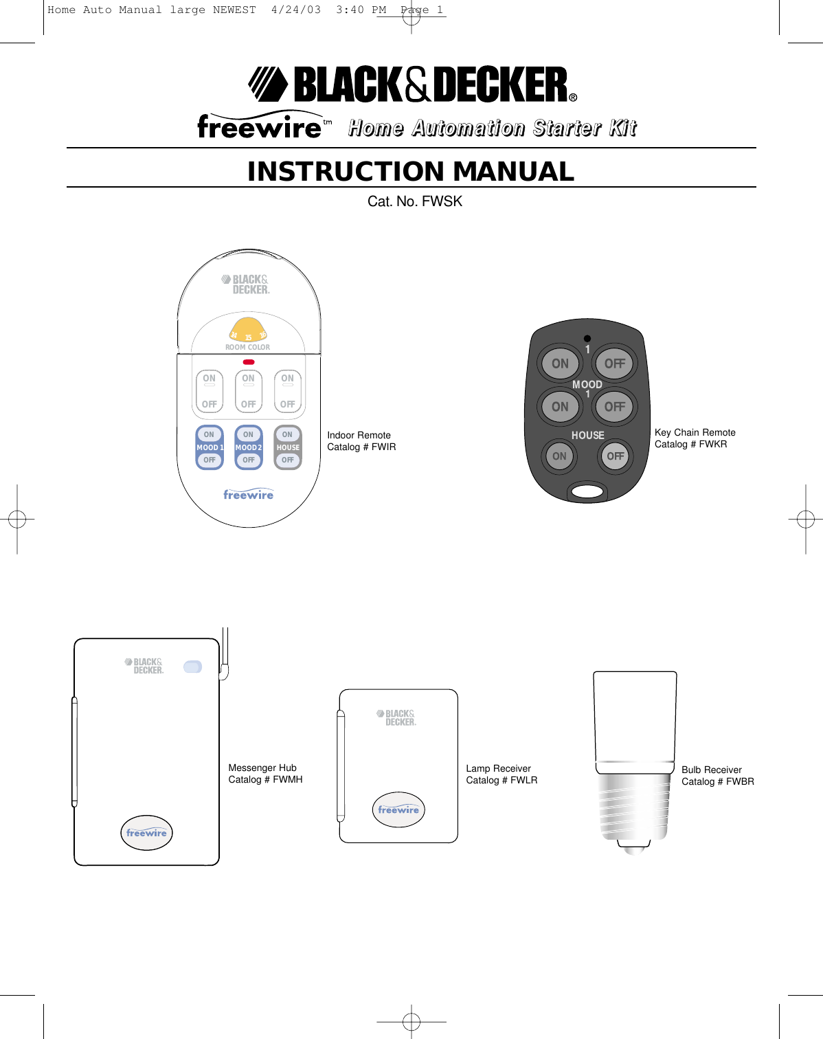
Authinx FWIR Indoor Remote User Manual Home Auto Manual large NEWEST

Authinx Inc. Indoor Remote Home Auto Manual large NEWEST

Exhibit D Users Manual per 2 1033 b3

INSTRUCTION MANUALCat. No. FWSKON OFF12346759810121113151614ROOM COLOR MOOD 2MOOD 1 HOUSEONOFFONOFFONOFFONOFFONOFFONOFFHHHHoooommmmeeee    AAAAuuuuttttoooommmmaaaattttiiiioooonnnn    SSSSttttaaaarrrrtttteeeerrrr    KKKKiiiittttIndoor RemoteCatalog # FWIRMessenger HubCatalog # FWMH Lamp ReceiverCatalog # FWLRKey Chain RemoteCatalog # FWKRBulb ReceiverCatalog # FWBRHome Auto Manual large NEWEST  4/24/03  3:40 PM  Page 1
General Safety RulesWARNING: Read and understand all instructions. Failure to follow all instructions listed below may result in electric shock, fire and/or seriouspersonal injury.SAVE THESE INSTRUCTIONSCAUTION: To reduce the risk of electric shock, do not disassemble any parts. No user-serviceable parts are inside. If you spill liquid on aunit, disconnect the unit from the AC outlet to prevent possible fire or shock hazard and consult authorized service personnel.WARNING: To prevent electric shock hazard, do not expose any part to rain or moisture.WARNING: Use only incandescent bulbs in lamps that are to be controlled by Lamp Receivers. Using any other type bulbs could damagebulbs and or Lamp Receivers. Attempting to control any other device by the Lamp Receivers, may damage that device and may damage theLamp Receiver.FCC CautionTHIS DEVICE COMPLIES WITH PART 15 OF THE FCC RULES.OPERATION IS SUBJECT TO THE FOLLOWING TWO CONDITIONS:(1) THIS DEVICE MAY NOT CAUSE HARMFUL INTERFERENCE, AND(2) THIS DEVICE MUST ACCEPT ANY INTERFERENCE RECEIVED, INCLUDING INTERFERENCE THAT MAY CAUSE UNDESIRED OPERATION.This equipment generates and uses radio frequency energy, and if not installed and used properly, that is, in strict accordance with themanufacturers instructions, it may cause interference to radio and television reception. It has been type tested and found to comply with thelimits for remote control devices in accordance with the specifications in Sub Parts B and C of Part 15 of FCC Rules, which are designed toprovide reasonable protection against such interference in a residential installation. However, there is no guarantee that interference will notoccur in a particular installation. If this equipment does cause interference to radio or television reception, which can be determined by unplugging the equipment, tryto correct the interference by one or more of the following measures. • Reorient the antenna of the radio/TV experiencing the interference.• Relocate the interference with respect to the radio/TV.• Move the interference away from the radio/TV.• Plug the interface into an outlet on a different electrical circuit from the radio/TV experiencing the interference.• If necessary, consult your local Dealer for additional suggestionsNOTE: Modifications to any of the components in this kit will void the user’s authority to operate this equipment.2Home Auto Manual large NEWEST  4/24/03  3:40 PM  Page 2
3ON OFF12346759810121113151614ROOM COLOR MOOD 2MOOD 1 HOUSEONOFFONOFFONOFFONOFFONOFFONOFFINDOOR REMOTELAMP RECEIVERBULB RECEIVERMESSENGER HUBKEY CHAIN REMOTEThe MESSENGER HUB is the brain of the Freewiretm system. When it is plugged into an ACoutlet it has the ability to receive Radio Frequency (RF) signals from the remotes and theability to send messages through existing house wiring to all receivers that are dialed to thesame house code.  It is also used to control *incandescent lamps only, rated up to 500 watts, connected to theplug receptacle at the bottom of the MESSENGER HUB.  Note: For restrictions andinstructions see MESSENGER HUB section.*Do not use fluorescent, low wattage, energy saving and halogen bulbs.The INDOOR REMOTE sends Radio Frequency (RF) signals to the MESSENGER HUB.These signals can go through walls, so you can use this remote to control lights (orappliances with approved appliance receiver only) from anywhere in or around your home. NOTE: Walls and other obstructions may reduce the effective range of the RF signal.A LAMP RECEIVER must be used in conjunction with at least one active MESSENGERHUB.  It is used to control *incandescent lamps only rated up to 300 watts.  Note: Forrestrictions and instructions see LAMP RECEIVER section.*Do not use fluorescent, low wattage, energy saving and halogen bulbs.The BULB RECEIVER must be used in conjunction with at least one MESSENGER HUB.  Itis used to control an indoor or outdoor incandescent light (up to 150 watts) that is normallycontrolled by a wall switch.  *Do not use fluorescent, low wattage, energy saving and halogen bulbs.The KEY CHAIN REMOTE can conveniently turn on and off a limited number of lights whichyou select from the MESSENGER HUB. NOTE: For restrictions and instructions see KEYCHAIN REMOTE sectionGetting familiar with your    home automation kit.Home Auto Manual large NEWEST  4/24/03  3:40 PM  Page 3
4PLEASE FOLLOW THE SEQUENCE LAID OUT IN THIS MANUAL TO AVOID CONFUSIONStep by step instructions to set up the MESSENGER HUB:A Quick Note Before You Set Up MESSENGER HUB:WARNING: For indoor use only.Each receiver has a specific address made up of a HOUSE CODE (bottom dial) and a Unit Code (upper dial) which is used to communicate withthe MESSENGER HUB.  The function of the HOUSE CODE is to prevent interference from another FREEWIRE system.  If at any time, you experience interference withanother system please choose another setting for your HOUSE CODE A - P.  The letter selected must be the same on all RECEIVERS and theMESSENGER HUB.Step 1:Plug MESSENGER HUB into any operational AC outlet within your home.  Rotateantenna to the upright position.  Open the front door to expose control panel asshown in Figure 1. NOTE:  Placing the MESSENGER HUB on the inside wallclosest to driveway or entry way, will often maximize range of the KEY CHAINREMOTE.Step 2:Select a HOUSE CODE on the MESSENGER HUB, any letter A- P.  (Note: Thehouse code you select for the MESSENGER HUB will dictate what letter you willselect for all of the RECEIVERS you plan to control with this MESSENGER HUB.)Step 3:Select a UNIT CODE on the MESSENGER HUB, any number 1 - 16. The numberand corresponding color you pick will control the lamp outlet located on theunderside of this MESSENGER HUB.  (If you select the same number and same house code for any additionalreceivers on this system they will operate in conjunction with this hub.)  Step 4:Synchronize your INDOOR REMOTE with your MESSENGER HUB so they understand how to communicate with each other.  (Note: Anyadditional remote that is introduced to the system must also be synchronized.)  To synchronize, move the MESSENGER HUB slide switch to LEARN.         While facing the MESSENGER HUB, press and hold any “ON” button of the INDOOR REMOTE for 5seconds - Figure 2. Be sure to see the green light flash on the MESSENGER HUB.  The flash will indicatethat the MESSENGER HUB is now synchronized with the INDOOR REMOTE.Now, move the slide switch on the MESSENGER HUB to RUN. (Note: Door cannot be closed while MESSENGER HUB is in the LEARN mode.) Step 5:Turn lamp on first, then plug into the receptacle on the underside of the MESSENGER HUB. Use onlyincandescent bulbs up to 500W. Be sure the Lamp has been turned on prior to plugging into MESSENGERHUB.Press the Local Lamp “ON/OFF” button on the MESSENGER HUB to check that the MESSENGER HUB isoperating correctly. You will hear a “click” when the MESSENGER HUB turns this lamp on and off.You are now ready to operate the lamp connected to this MESSENGER HUB with the INDOOR REMOTE.Unit Code DialHouse Code Dial1ON OFF12346759810121113151614ROOM COLOR MOOD 2MOOD 1 HOUSEONOFFONOFFONOFFONOFFONOFFONOFFPress any“ON” buttonfor 5 seconds2On/Off ButtonRun / Learn Slide SwitchPlug ReceptacleHome Auto Manual large NEWEST  4/24/03  3:40 PM  Page 4
Step by step instruction to operate the INDOOR REMOTE:A Quick Note before You Set Up the INDOOR REMOTE:WARNING: For indoor use only.Open door to the INDOOR REMOTE to expose the colored dial shown in Figure 3.The numbers and colors on the INDOOR REMOTE's dial match the numbers and colors on the MESSENGER HUBand LAMP RECEIVERS.  The colors on the dial for the Unit Code can be used to divide your home into zones with up to 3 dedicated UnitCodes per color (except red which only has one Unit Code.)  (eg. Green = Living Room) The numbers are used to differentiate one receiver from another in each color/zone.Reference Label Set UpFor your convenience, a blank reference label is located on the back of your INDOOR REMOTE. Write your owncustomized applications on this blank key.  Figure 4:Example: Red Unit Codes have been selected for the BULB RECEIVER in the EntranceGray Unit Codes have been selected for the RECEIVERS in the Dining RoomGreen Unit Codes have been selected for the RECEIVER in the Living Room etc.NOTE: The top button on the KEY CHAIN REMOTE will only activate UNIT CODE 1(RED). We recommend thatyou control the lighting near your entrance way by UNIT CODE 1(Red ) so that it can be activated by your KEYCHAIN REMOTE. See KEY CHAIN REMOTE instructions on page 8 for further instructions.Step 1:Set the dial on your INDOOR REMOTE to the same UNIT CODE (color) that you selected on the MESSENGER HUB in the previous section.  Step 2:Each of the 3 individual codes on that color can be turned on and off individually, using the 3 white ON/OFF buttonslocated just below the dial as shown in Figure 5.Example: Gray 2 - Controlled by the top row, left switch Gray 3 - Controlled by the top row, center switch Gray 4 - Controlled by the top row, right switch.The small round ON button and OFF button shown in Figure 6 allow you to turn on or off all RECEIVERS set tothat color. You should now be able to turn the lamp on and off with the corresponding button on the INDOOR REMOTE. Note: You may have to press and momentarily hold the button before it activates. INDOOR REMOTE Battery ReplacementOpen the battery compartment clip (located on the bottom of the back cover) with your fingernail and install a CR2032 replacement lithium batteryas shown in Figure 7. Note: Writing on battery must face back cover of INDOOR REMOTE or INDOOR REMOTE will not operate.5ON OFF123467598101211131516143ON ON ONON OFF123467581654ON ON ONON OFF1234675981012111315161467Home Auto Manual large NEWEST  4/24/03  3:40 PM  Page 5
Step by step operating instructions for the LAMP RECEIVERSA Quick Note before You Set Up the LAMP RECEIVERs:WARNING: For indoor use only.Use incandescent bulbs up to 300 watts only.Step 1:Set the HOUSE CODE to the same letter that you selected on the MESSENGER HUB, then plug the LAMP RECEIVER into the AC outletcurrently being used by the lamp you wish to control. Step 2:Select a UNIT CODE color to match the room color that you laid out on the back of the INDOOR REMOTE. Nowyou will need to assign a specific UNIT CODE for the LAMP RECEIVER. Within the color that you have picked youhave 3 number choices. In the example in Figure 8 the LAMP RECEIVER is set to Yellow 8. Step 3:Turn lamp on first, then plug into the receptacle on the underside of the MESSENGER HUB.Step 4:Turn color dial on INDOOR REMOTE so that it matches the color setting on the LAMP RECEIVER. Toturn the lamp on and off, press the switch which corresponds with the number selected on the LAMPRECEIVER.  Figure 9 depicts activating LAMP RECEIVER set to Yellow 8.NOTE: Lamps connected to LAMP RECEIVERS can still be controlled by the lamps switch. Rememberthat lamp switch must be turned on in order for the lamp to be controlled by the Freewire system.MOOD 2MOOD 1 HOUSEONOFFONOFFONOFFONOFFONOFFONOFFON OFF12346759810121113151614961161514131211 10 987654328Home Auto Manual large NEWEST  4/24/03  3:40 PM  Page 6
Step by step operating instructions for the BULB RECEIVERA Quick Note before You Set Up the BULB RECEIVERs:The BULB RECEIVER can be used indoors and outdoors.WARNING:  To keep rain out when used outdoors, mount the BULB RECEIVER  in the orientation shown in Figure 10.Unlike LAMP and APPLIANCE RECEIVERS the BULB RECEIVER does not have any code wheels. You set its code upfrom the MESSENGER HUB and it then remembers this code, even after a power outage. For ease of programming, initiallyplace the BULB RECEIVER in a lamp that can be set up in the same wall outlet that the MESSENGER HUB is plugged into.After programming you can move it to its final location (in an outdoor light fixture for example).Step 1:Make sure the lamp is turned to the “ON” position and then it must be unplugged! Unscrew your existing light bulbfrom its socket and screw the BULB RECEIVER into the light socket as shown in Figure 11.  CAUTION: BULBRECEIVER raises the bulb approximately two inches. If bulb touches lamp shade or lamp frame, you must purchase ashorter bulb to use this lamp. Screw an incandescent light bulbs only (up to 150W) into the BULB RECEIVER. DO NOTuse with fluorescent lamps. Step 2:Set the unit code on the INDOOR REMOTE to the color and number that you want to use to control the BULB RECEIVERin its final location. (Example : Red 1) Step 3:Plug the lamp into the same wall outlet as the MESSENGER HUB or you can move the MESSENGER HUB andplug into the same wall outlet as the lamp. (The Messenger Hub will not lose its memory and it can be movedback later.) See Figure 12.  Within 30 seconds of plugging lamp in, press and hold for 5 seconds the on button on the INDOOR REMOTE thatcorresponds to the UNIT CODE that you have selected. The light should turn on.NOTE: If the light does not turn on in 5 seconds, unplug the lamp and then re-plug and repeat step 3. If lamp stilldoes not turn on, move the MESSENGER HUB and lamp to a different outlet in a different room and repeat step 3.Step 4:If you wish to use the BULB RECEIVER in a different lamp, unplug lamp, remove bulb and BULB RECEIVER.Place BULB RECEIVER in new lamp. BULB RECEIVER will remember unit code setting that was established instep 3.BULB RECEIVER NOTES:• You must leave the lamp switch or wall switch on at all times otherwise the BULB RECEIVER will have no AC power and you won’t be able to control it remotely.• The BULB RECEIVER does not have local control (you cannot turn the light on from its regular switch).• The BULB RECEIVER does not respond to bright and dim commands. It does respond to ALL lights On and ALL units Off commands.NOTE: When using the BULB RECEIVER, you cannot control the lamp by the lamps switch. Turning the lamp switch off will cause the BULBRECEIVER to go into program mode and will need to be reprogrammed. See page 7.1011712Home Auto Manual large NEWEST  4/24/03  3:40 PM  Page 7
Step by step instruction to developing MOOD SETTINGSA Quick Note before You Program the Mood Settings:In the Lamp Receiver section you learned how to set up individual LAMP RECEIVERs. These LAMP RECEIVERs are turned on and off bypressing the appropriate rocker switch that corresponds to the receivers unique UNIT CODE. The purpose of the MOOD buttons (blue) are to linkmultiple receivers (up to 4) so that they can be turned on or off by the MOOD button. See Figure 16.Example:  If you have a LAMP RECEIVER in one room and it is set to the number 7 on its UNIT CODE and you have another LAMP RECEIVERin another room and it is set up to the number 13 on its UNIT CODE, the two lamps can be turned on at the same time using a MOOD. Step1:With the MESSENGER HUB still plugged into an AC outlet, set the slide switch to LEARN as shown in Figure 15. Step 2:While facing the MESSENGER HUB, press MOOD 1 ON switch on the INDOOR REMOTE.  Figure 16 -The MESSENGER HUB’s green indicator light will flash.Step 3:Set the UNIT CODE dial of the INDOOR REMOTE to match the UNIT CODE of the LAMP RECEIVERthat you want to turn on and off. Press on the rocker switch (white) corresponding to that LAMPRECEIVER as shown in Figure 17. Wait for the MESSENGER HUB indicator to flash indicating the codehas been stored in the MOOD function.Step 4:Repeat step 3 a maximum of 3 more times to link up to 4 LAMP RECEIVERs / BULB RECEIVERs withthat MOOD key. The 4 LAMP RECEIVERs can be in any combination of UNIT CODES.Step 5:Return the slide switch on the MESSENGER HUB to RUN - Figure 18. The ON/OFF button of MOOD1 will now turnon and off all of the LAMP RECEIVERs / BULB RECEIVERs that were linked in Step 4. There may be up to a 3 seconddelay between the time that you press the button and the time that the lights respond.Step 6:To set up MOOD 2 key,  repeat steps 1 thru 5 substituting MOOD 2 key for MOOD 1.NOTE: Pressing either MOOD ON key while in LEARN mode clears all stored codes for that MOOD.Using ALL on, ALL off House ButtonPressing the INDOOR REMOTE HOUSE BUTTON (figure 19) on and off will activate the MESSENGER HUB and ALL theLAMP RECEIVERs / BULB RECEIVERs set to the system’s HOUSE CODE. 8MOOD 2MOOD 1 HOUSEONOFFONOFFONOFF16ON ON ONON OFF34675981718HOUSEONOFF15ONOFFONOFFONOFFON OFF2345MOOD 2MOOD 1 HOUSEONOFFONOFFONOFFUnit Code DialHouse Code DialRun / Learn Slide SwitchRocker SwitchMood Button House ButtonRocker Switch13 1419Home Auto Manual large NEWEST  4/24/03  3:40 PM  Page 8
A Quick Note before You Set Up the KEY CHAIN REMOTE:The KEY CHAIN REMOTE is very convenient for switching on entrance lights while approaching your home. It lets you turn on and off theReceivers that are set to UNIT CODE 1 (RED) and MOOD 1 on your INDOOR REMOTE and activate all Receivers (same as the House buttonon the INDOOR REMOTE).Step by step instructions to set up the KEY CHAIN REMOTEStep 1:Set the MESSENGER HUB slide switch to LEARN.Step 2:While facing the MESSENGER HUB, press and hold the top ON button on the KEY CHAIN REMOTE.The green light on the MESSENGER HUB flashes to indicate that the MESSENGER HUB nowrecognizes the KEY CHAIN REMOTE.Step 3:Set the slide switch on the MESSENGER HUB to RUN.The KEY CHAIN REMOTE is now ready for use.The top ON and OFF buttons will activate any Receivers set to UNIT CODE 1 (RED). For convenience we recommend that your entrancelights be controlled by UNIT CODE 1 (RED).The middle ON and OFF (MOOD 1) buttons of the KEY CHAIN REMOTE will activate all Receivers programmed on the MOOD 1 setting onyour INDOOR REMOTE. NOTE: You must have already programmed the MOOD 1 setting on your INDOOR REMOTE for this function of theKEY CHAIN REMOTE to operate.The bottom ON and OFF buttons of the KEY CHAIN REMOTE perform the same function as the House button on the INDOOR REMOTE.Pressing the ON and OFF buttons will activate the MESSENGER HUB and all the LAMP RECEIVERs / BULB RECEIVERs set to the system’sHOUSE CODE.  KEY CHAIN REMOTE BATTERY REPLACEMENTTo change the battery, pry the two halves apart and fit two CR2016 Lithium 3V batteries. Observe the polarity of the batteries. (Writing on backof battery must face back cover of KEY CHAIN REMOTE.Activates UNITCODE 1 (RED) onlyActivatesMOOD 1 onlyActivates allOn or all Off920Home Auto Manual large NEWEST  4/24/03  3:40 PM  Page 9
TROUBLESHOOTINGDIFFICULTY PROGRAMMING RECEIVERSIf you are experiencing problems when programming the BULB RECEIVER, it may be due to electrical interference on the power lines causedby large appliances such as refrigerators or TV’s. To avoid the interference, move the Receiver while it is being programmed to a different walloutlet that is further away from large appliances.SOME RECEIVERS DON’T RESPOND Most houses are fed from a 220 volt service which is then split into two phases of 110 volts each in the circuit breaker panel. The mostcommonly encountered problem with systems which use the existing house wiring to transmit signals is that the signals are received by someReceivers, but not by others. For example, the MESSENGER HUB controls some lights but not others or controls some lights intermittently.This can happen sometimes when the Receiverto be controlled is on the opposite phase of the house wiring to the phase which theMESSENGER HUB is connected to.If some of the Receivers are not working it may be necessary to:• move the Receiver to a different wall outlet to test that it works.If it still doesn’t work:• move the Receiver to a different room. If it still doesn’t work:• move the Receiver to the closest outlet that the MESSENGER HUB is plugged into or move the MESSENGER HUB to the closest outlet to theReceiver that is not working.RECEIVERS TURN ON BY THEMSELVES If it is suspected that Receivers have turned on by themselves, the first step should be to change the HOUSE CODE on the MESSENGERHUB and all Receivers. It is possible that a neighbor has the same system or another compatible system.THREE WAY BULBS AND TOUCH ACTIVATED LAMPSCAUTION: Touch activated lamps should not be used with LAMP RECEIVERS or BULB RECEIVERS, damage to lamp may occur.Three way bulbs may be used, however, only one level of brightness can be activated using the Freewire system. To change brightness levelyou will need to turn the switch at the lamp to the desired level of brightness. NOTE: When using the BULB RECEIVER, you cannot control the lamp by the lamps switch. Turning the lamp switch off will cause the BULBRECEIVER to go into program mode and will need to be reprogrammed. See page 7.WIRELESS INTERCOMSIntercom systems which use the house wiring to transmit can “block out” FREEWIRE transmissions while the intercom is left in the permanenttransmit (talk) mode.It is NOT possible to have a wireless intercom and a MESSENGER HUB operating in the same house. It is possible that aneighbor’s wireless intercom could affect your system.KEY CHAIN REMOTE RANGE OF USEPlacing the MESSENGER HUB on the inside wall closet to driveway or entry way, will often maximize range of KEY CHAIN REMOTE.SOME DON’TS•Don’t use a LAMP RECEIVER to control a lamp or fixture which already has a dimmer on it.•Don’t leave a wireless intercom or baby monitor in the permanent transmit (or talk) mode. Its transmissions could “block out” FREEWIREtransmissions.•Don’t exceed the rating of the Receivers, these are:•  BULB RECEIVER - 150 watts - incandescent bulbs only.•  LAMP RECEIVER - 300 watts - incandescent bulbs only.•  MESSENGER HUB - 500 watts - incandescent bulbs only.10Home Auto Manual large NEWEST  4/24/03  3:40 PM  Page 10

Navigation menu