Authinx VR46A WIRELESS AUDIO/ VIDEO SENDER WITH IR EXTENDER User Manual 1
Authinx Inc. WIRELESS AUDIO/ VIDEO SENDER WITH IR EXTENDER 1
Authinx >
USERS MANUAL
CAT. NO. 15-2572
WW
WW
WIRELESSIRELESS
IRELESSIRELESS
IRELESS A A
A A
A
UDIOUDIO
UDIOUDIO
UDIO/V/V
/V/V
/VIDEOIDEO
IDEOIDEO
IDEO S S
S S
S
ENDERENDER
ENDERENDER
ENDER
with IR Extender Feature
SENDER 15-2572T
OWNER’S MANUAL
SENDER 15-2572T

32
FCC CAUTION
THIS DEVICE COMPLIES WITH PART 15 OF THE FCC RULES.
OPERATION IS SUBJECT TO THE FOLLOWING TWO
CONDITIONS:
(1) THIS DEVICE MAY NOT CAUSE HARMFUL INTERFERENCE,
AND
(2) THIS DEVICE MUST ACCEPT ANY INTERFERENCE
RECEIVED, INCLUDING INTERFERENCE THAT MAY CAUSE
UNDESIRED OPERATION.
NOTE: Modifications to this product will void the user’s authority to
operate this equipment.
INTRODUCTION
Your Wireless Audio/Video Sender system consists of a Sender unit which
you connect to your satellite receiver, DVD player, etc., and a Receiver
unit that you connect to a TV anywhere in your home. The Audio/Video
Sender converts the A/V signal from your A/V product into a 2.4 GHz
wireless Radio Frequency (RF) signal and transmits it (even through walls)
to the Audio/Video Receiver unit. The Audio/Video Receiver converts the
signal back to an A/V signal and passes it through a cable to your TV’s
COAX input, or A/V input jacks.
The Audio/Video Sender system also includes an IR Extender feature. This
lets you remotely control the A/V product that the Sender is connected to,
from the location where the Receiver is located. For example, you can
control a DVD Player in your living room, while watching it on a TV in
your bedroom.
There are just a few simple steps to follow to hook up your Audio/Video
Sender system to a satellite receiver, VCR, DVD Player, or Cable Box.
CONTENTS
INTRODUCTION ........................................................................ 3
CONTROLS AND CONNECTIONS .................................................. 4
SENDER ............................................................................ 4
RECEIVER .......................................................................... 5
CONNECTING UP..................................................................... 6
HOOKING UP THE SENDER .................................................... 6
HOOKING UP THE RECEIVER ................................................. 8
FINE TUNING YOUR SYSTEM .................................................... 10
IR EXTENDER FEATURE ......................................................... 11
54
DC 6V
CHANNEL
ONOFF
TV CHANNEL
34
ONOFF
CHANNEL
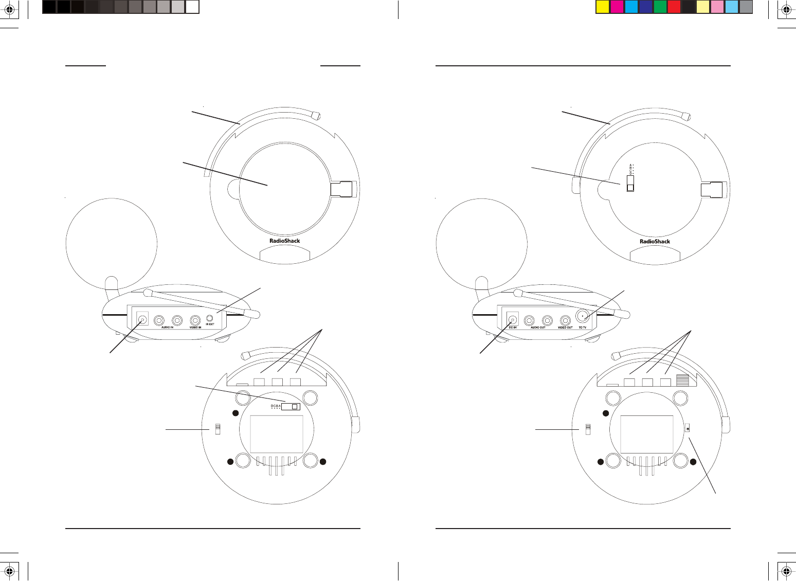
RF Antenna
(for use with the IR
Extender feature)
Power Supply
Jack
2.4 GHz
Antenna
2.4 GHz
Channel Switch
A/V In Jacks
2.4 GHz Channel
Switch (underneath
2.4 GHz Antenna).
CONTROLS AND CONNECTIONS
Audio/Video ReceiverAudio/Video Sender
ON-OFF
Switch
(on side)
A/V Out Jacks
COAX out
Channel 3/4
switch
IR Extender Jack
RF Antenna
(for use with the IR
Extender feature)
Power Supply
Jack
ON-OFF
Switch
(on side)
76
Video Audio
Out
In
Out
Video Audio
A
/V Component
Antenna To TV
Antenna
TV
A
/V Component
Antenna To TV
Antenna
TV
Out
Video Audio
UHF/VHF
To TV
UHF/VHF
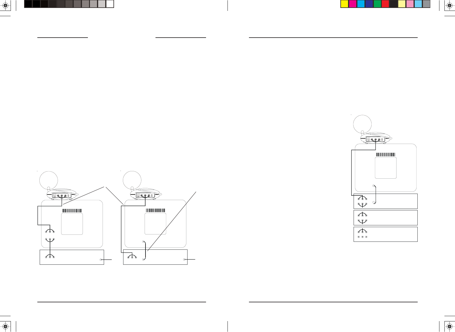
CONNECTING UP
Hooking up the Audio/Video Sender
1. Connect one set of Audio/Video cables to the VIDEO and AUDIO
jacks of your Audio/Video Sender. Take care to match the colors of the
plugs on the cable with the jacks on the Audio/Video Sender.
2. Connect the other end of the cable to the Audio/Video OUT jacks on
your TV. Take care to match the colors of the plugs on the cable with
the jacks on the TV. If the jacks on the TV are colored differently,
connect the yellow plug to the jack labelled VIDEO, the red plug to the
jack labelled AUDIO RIGHT and the white plug to the jack labeled
AUDIO LEFT. See diagram A below.
Note: If your TV does not include Audio/Video OUT jacks, you will
need to remake the connections as shown in diagram B) using the
TV antenna (coaxial) connections to link up a Satellite Receiver
(DBS), or Cable Box, or VCR, or DVD Player to your TV.
3. Plug the Audio/Video Sender’s Power Supply into a convenient 120 volt
wall outlet and plug its jack into the Audio/Video Sender.
4. Position the Audio/Video Sender in a convenient location such as on top
of your TV and orient the antenna so that the flat side points in the
direction of the room where you will be installing the Receiver.
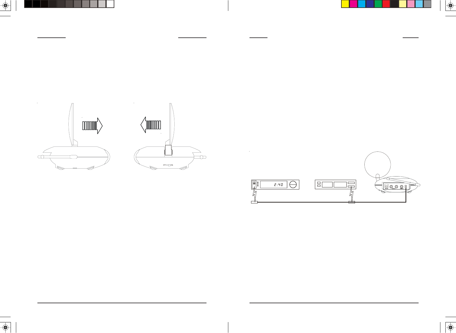
If you have several A/V
components:
If you have two or more A/V
components (e.g. Satellite Receiver
(DBS), VCR, Cable Box, DVD Player,
etc.) that you want to watch in another
room, they will probably already be
hooked up to the local TV in series (see
the diagram to the right). To connect the
Audio/Video Sender you just need to
identify the last component in the chain
and connect its LINE OUT jacks to the
Audio/Video Sender’s A/V IN jacks.
If the last component in the chain does
not have spare LINE OUT jacks,
reconnect the local TV to the last
component in the chain using a coaxial
cable to connect to the VHF/UHF jack,
then use the A/V connections for the
Audio/Video Sender.
A) Connections for a TV
with A/V OUT jacks.
B) Connections for a TV
without A/V OUT jacks.
A/V Cables Coaxial
Cable
TV
UHF/VHF
Satellite Receiver
Out
Video Audio UHF/VHF
To TV
In
Cable Box
Out
Video Audio
In
DVD Player
Out
Video Audio
In
98
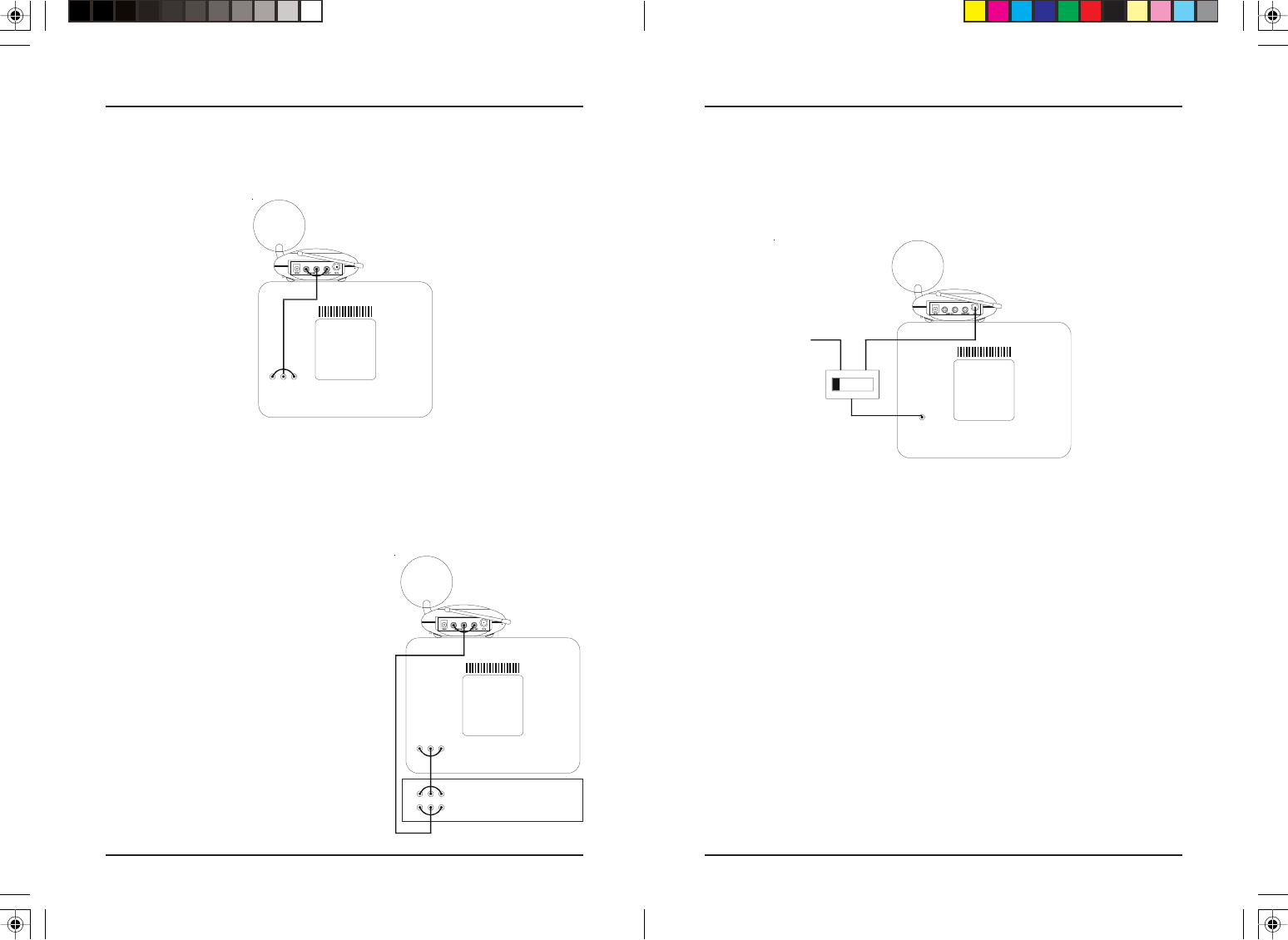
Hooking up the Audio/Video Receiver
1. Connect a set of Audio/Video cables to the A/V OUT jacks of your
Audio/Video Receiver. Connect the other end to your TV.
2. Plug the Audio/Video Receiver’s Power Supply into a 120 volt wall
outlet and plug its jack into the Audio/Video Receiver.
3. Position the Audio/Video Receiver in a convenient location such as on
top of your TV and orient the antenna so that the flat side points in the
direction of the room where you set up the Audio/Video Sender.
Video Audio
In
A
/V Component
TV
Out
Video Audio
In
Video Audio
TV
In
UHF/VHF
(COAX) In
TV
1 2
TV
UHF/VHF
From antenna
If your TV does not have A/V connectors:
You can use the supplied coaxial cable to connect the TV OUT COAX
socket on the Audio/Video Receiver to the Antenna input on your TV. If
you already have an antenna connected to your TV, you will need to use a
TV antenna splitter as shown below.
If your second TV is already hooked
up to a Satellite Receiver or other
A/V device:
If your Satellite Receiver or other A/V
component is connected to the TV using
A/V cables, you can connect the Audio/
Video Receiver to the free LINE IN
jacks on the component. If there are no
LINE IN jacks, you will need to use a
TV antenna splitter as described on the
next page.
Set your TV and the TV Channel switch on the Audio/Video Receiver (on
the bottom of the unit) to the same channel (3 or 4).
1110
FINE TUNING YOUR SYSTEM
The Wireless Audio/Video Sender usually works best with the flat faces of
the antennas on the Sender and Receiver units facing each other, see
diagram below. Sometimes, however, reflections and other effects in your
home may affect the signal so that some adjustment of either the Sender or
Receiver antenna might be necessary to get the best signal.
If you are not getting any sound or picture at all from the Receiver:
• Check that the CHANNEL slide switch (labeled A, B, C, D) on both
units is set to the same letter. The switch is on the bottom of the Sender
unit and it’s under the flip-up antenna on the Receiver unit.
• Check that both the Sender’s and Receiver’s power supplies are
plugged in.
• Check that the ON/OFF switch on the Sender and Receiver are ON.
If the video or sound is poor, or there is interference:
Try changing the channel on both units. Do this by adjusting the
CHANNEL slide switch on each unit to any position from A to D. Make
sure both units are set to the same letter.
VCR
DVD
IR emitter IR emitter IR extender jack
USING THE IR EXTENDER FEATURE
The IR extender feature lets you use your original remote control to control
the A/V product that the Audio/Video Sender is connected to. E.G., if the
Sender is connected to a DVD Player, or VCR in your living room, and the
Audio/Video Receiver is connected to a TV in your bedroom; you can
control the DVD Player or VCR while watching the picture from it on the
TV in your bedroom. You do this by pointing your remote control at the
Audio/Video Receiver that’s connected to your bedroom TV. It receives
the IR commands from your remote and converts them to wireless Radio
Frequency (RF) commands, and sends them to the Audio/Video Sender.
You plug the IR extender cable into the jack on the back of the Audio/
Video Sender and attach the IR emitters to the front of the DVD Player,
or VCR, etc. that you want to control.
Audio/Video
Sender.
1. Plug the IR extender jack on the IR emitter cord into the IR EXT.
socket located on the back of the Audio/Video Sender.
2. Place the emitter cord in front of the two devices you want to control
(e.g., DVD and VCR).
3. Make sure that the two IR emitters are attached close to the IR sensors
on the devices you want to control.
The IR emitter cord lets you control up to two IR devices.

15-2572-08/0615-2572-08/06
15-2572-08/0615-2572-08/06
15-2572-08/06
LIMITED NINETY-DAY WARRANTY
This product is warranted by RadioShack against manufacturing defects in material and
workmanship under normal use for ninety (90) days from the date of purchase from
RadioShack company-owned stores and authorized RadioShack franchisees and dealers.
EXCEPT AS PROVIDED HEREIN, RadioShack MAKES NO EXPRESS WARRANTIES
AND ANY IMPLIED WARRANTIES, INCLUDING THOSE OF
MERCHANTABILITY AND FITNESS FOR A PARTICULAR PURPOSE, ARE
LIMITED IN DURATION TO THE DURATION OF THE WRITTEN LIMITED
WARRANTIES CONTAINED HEREIN. EXCEPT AS PROVIDED HEREIN,
RadioShack SHALL HAVE NO LIABILITY OR RESPONSIBILITY TO CUSTOMER
OR ANY OTHER PERSON OR ENTITY WITH RESPECT TO ANY LIABILITY, LOSS
OR DAMAGE CAUSED DIRECTLY OR INDIRECTLY BY USE OR PERFORMANCE
OF THE PRODUCT OR ARISING OUT OF ANY BREACH OF THIS WARRANTY,
INCLUDING, BUT NOT LIMITED TO, ANY DAMAGES RESULTING FROM
INCONVENIENCE, LOSS OF TIME, DATA, PROPERTY, REVENUE, OR PROFIT OR
ANY INDIRECT, SPECIAL, INCIDENTAL, OR CONSEQUENTIAL DAMAGES,
EVEN IF RadioShack HAS BEEN ADVISED OF THE POSSIBILITY OF SUCH
DAMAGES.
Some states do not allow limitations on how long an implied warranty lasts or the
exclusion or limitation of incidental or consequential damages, so the above limitations or
exclusions may not apply to you. In the event of a product defect during the warranty
period, take the product and the RadioShack sales receipt as proof of purchase date to any
RadioShack store. RadioShack will, at its option, unless otherwise provided by law: (a)
correct the defect by product repair without charge for parts and labor; (b) replace the
product with one of the same or similar design; or (c) refund the purchase price. All
replaced parts and products, and products on which a refund is made, become the property
of RadioShack. New or reconditioned parts and products may be used in the performance
of warranty service. Repaired or replaced parts and products are warranted for the
remainder of the original warranty period. You will be charged for repair or replacement of
the product made after the expiration of the warranty period.
This warranty does not cover: (a) damage or failure caused by or attributable to acts of
God, abuse, accident, misuse, improper or abnormal usage, failure to follow instructions,
improper installation or maintenance, alteration, lightning or other incidence of excess
voltage or current; (b) any repairs other than those provided by a RadioShack Authorized
Service Facility; (c) consumables such as fuses or batteries; (d) cosmetic damage; (e)
transportation, shipping or insurance costs; or (f) costs of product removal, installation,
setup service adjustment or reinstallation.
This warranty gives you specific legal rights, and you may also have other rights which
vary from state to state.
RadioShack Customer Relations, 200 Taylor Street, 6th Floor, Fort Worth, TX 76102
Custom Manufactured in China for RadioShack, Ft. Worth, TX 76102.