Authinx VT50A WIRELESS AUDIO/VIDEO SENDER User Manual VK50A OM pmd
Authinx Inc. WIRELESS AUDIO/VIDEO SENDER VK50A OM pmd
Authinx >
USERS MANUAL
MODEL VK50A
WW
WW
WIRELESSIRELESS
IRELESSIRELESS
IRELESS A A
A A
A
UDIOUDIO
UDIOUDIO
UDIO/V/V
/V/V
/VIDEOIDEO
IDEOIDEO
IDEO S S
S S
S
ENDERENDER
ENDERENDER
ENDER
with dual-source input
and IR Extender Feature
SENDER - MODEL VT50A
OWNER’S MANUAL
RECEIVER - MODEL VR50A

32
INTRODUCTION
Your Wireless Audio/Video Sender system consists of a Sender unit which
you connect to your satellite receiver, DVD player, etc., and a Receiver
unit that you connect to a TV located somewhere else in your home. The
Audio/Video Sender converts the audio and video output from your A/V
product into a 5.8 GHz wireless Radio Frequency (RF) signal and
transmits it (even through walls) to the Audio/Video Receiver. The Audio/
Video Receiver converts the signal back to an A/V signal and passes it
through a cable to your TV’s Audio/Video input jacks.
You can connect two A/V devices to the Audio/Video Sender and you
can select which of these two sources is transmitted to the Audio/Video
Receiver - and you can select this remotely, from the location where the
Audio/Video Receiver is located.
The Audio/Video Sender system also includes an IR Extender feature.
This lets you remotely control the A/V products that are connected to the
Sender, from the location where the Receiver is located. For example, you
could pause a DVD Player in your living room, or change channels on a
Satellite Box in your living room, while watching it on a TV in your
bedroom.
There are just a few simple steps to follow to hook up your Audio/Video
Sender system to a satellite receiver, VCR, DVD Player, or Cable Box.
CONTENTS
INTRODUCTION ........................................................................ 3
CONTROLS AND CONNECTIONS .................................................. 4
SENDER ............................................................................ 4
RECEIVER .......................................................................... 5
CONNECTING UP..................................................................... 6
HOOKING UP THE SENDER .................................................... 6
HOOKING UP THE RECEIVER ................................................. 8
SWITCHING SOURCES BY REMOTE CONTROL ............................... 8
IR EXTENDER FEATURE ........................................................... 9
FINE TUNING YOUR SYSTEM .................................................... 10
54
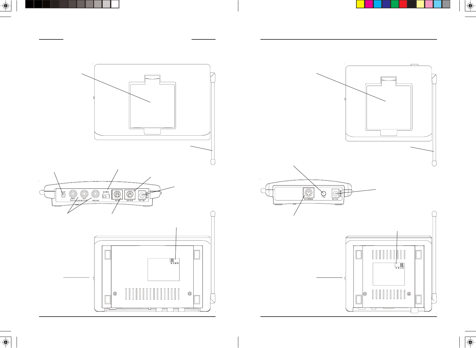
RF Antenna
(for use with the IR
Extender feature)
5.8 GHz
Antenna
CONTROLS AND CONNECTIONS
Audio/Video ReceiverAudio/Video Sender
RF Antenna
(for use with the IR
Extender feature)
Power Supply
Jack
ON-OFF
Switch
A/V Out 5.8 GHz Channel
Switch
5.8 GHz
Antenna
Power Supply
Jack
A/V In
(Source 1)
IR Extender Jack
5.8 GHz Channel
Switch
A/V In
(Source 2)
A/V Out
A/V Out
selector switch
Source 1 or 2
selector button
ON-OFF
Switch
76
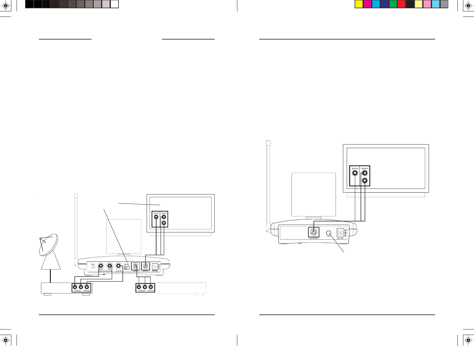
Satellite Box
(source 1) Back
DVD Player
(source 2) Back
Hooking up the Audio/Video Receiver
1. Using the special cable supplied connect the A/V OUT jack on the
Audio/Video Receiver to your TV.
2. Plug the Audio/Video Receiver’s Power Supply into a 120 volt wall
outlet and plug its jack into the Audio/Video Receiver.
3. Position the Audio/Video Receiver in a convenient location such as on
top of your TV and orient the antenna so that the flat side points in the
direction of the room where you set up the Audio/Video Sender.
CONNECTING UP
Hooking up the Audio/Video Sender
1. Connect one end of the supplied Audio/Video cable to an A/V device
and the other end to the VIDEO and AUDIO jacks of the Audio/Video
Sender. Take care to match the colors of the plugs on the cable with
the jacks on the Audio/Video Sender.
2. If desired connect a second A/V device to the Audio/Video Sender
using the special cable provided.
3. Using the cable supplied connect the A/V OUT on the Audio/Video
Sender to the Audio/Video IN jacks on your TV. See diagram below.
4. Plug the Audio/Video Sender’s Power Supply into a convenient 120 volt
wall outlet and plug its jack into the Audio/Video Sender.
5. Position the Audio/Video Sender in a convenient location such as on top
of your TV and orient the antenna so that the flat side points in the
direction of the room where you will be installing the Receiver.
Selects which of the
2 sources is viewed
on this TV.
Press the button on the back of the Receiver to select the source that’s
connected to the Sender unit (source 1 or source 2) that you want to view
on the TV connected to the Receiver. See next page for how to switch
sources by remote control.
Source 1 or 2
selector button
98
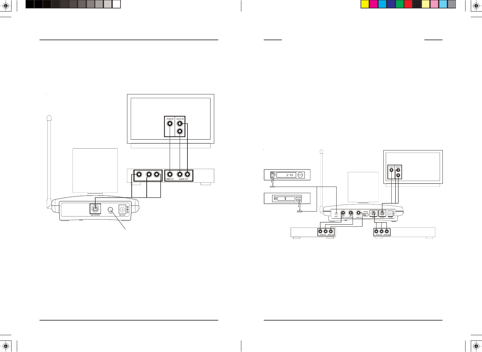
IR emitter
Satellite Box
(source 1) Front
DVD Player
(source 2) Front
IR emitter
Satellite Box
(source 1) Back
DVD Player
(source 2) Back
If your second TV is already hooked up to another A/V device:
If a Satellite Receiver or other A/V device is already connected to the TV
that you want to connect the Audio/Video Receiver to, you can connect the
Audio/Video Receiver to the free LINE IN jacks on the A/V device, using
the special cable provided.
A
V COMPONENT
V
IDEO IN AUDIO IN
USING THE IR EXTENDER FEATURE
The IR extender lets you use your remote to control the A/V product that
the A/V Sender is connected to. E.G., if the Sender is connected to a
DVD Player, or Satellite box in your living room, and the Audio/Video
Receiver is connected to a TV in your bedroom; you can control the DVD
Player or Satellite box while watching the picture from it on the TV in your
bedroom. You do this by pointing your remote control at the Audio/Video
Receiver that’s connected to your bedroom TV. It receives the IR
commands from your remote and converts them to wireless Radio
Frequency (RF) commands, and sends them to the Audio/Video Sender.
You plug the IR extender cable into the jack on the back of the A/V
Sender and attach the IR emitters to the front of the DVD Player, or
Satellite box, etc., that you want to control.
Audio/Video Sender.
Model VT50A
1. Plug the IR extender jack on the IR emitter cord into the IR EXT socket
located on the back of the VT50A Sender.
2. Attach the emitters in front of the devices you want to control.
3. Make sure that the IR emitters are attached close to the IR sensors on
the devices you want to control.
The IR emitter cord lets you control up to 3 IR devices.
Press the button on the back of the Receiver to select the source that’s
connected to the Sender unit (source 1 or source 2).
Switching sources by remote control
Point your IR remote control (any kind of remote control) at the Audio/
Video Receiver and press ANY button on the remote for about 10 seconds.
This will switch between sources (source 1 or source 2) that’s connected to
the Sender unit. I.E. you can select which source (connected to the Sender)
it transmitted to the Receiver.
Source 1 or 2
selector button
FCC Caution
THIS DEVICE COMPLIES WITH PART 15 OF THE FCC RULES.
OPERATION IS SUBJECT TO THE FOLLOWING TWO CONDITIONS:
(1) THIS DEVICE MAY NOT CAUSE HARMFUL INTERFERENCE, AND
(2) THIS DEVICE MUST ACCEPT ANY INTERFERENCE RECEIVED, INCLUDING
INTERFERENCE THAT MAY CAUSE UNDESIRED OPERATION.
This equipment generates and uses radio frequency energy, and if not installed and
used properly, that is, in strict accordance with the manufacturers instructions, it may
cause interference to radio and television reception. It has been type tested and
found to comply with the limits for remote control devices in accordance with the
specifications in Sub-Parts B and C of Part 15 of FCC Rules, which are designed to
provide reasonable protection against such interference in a residential installation.
However, there is no guarantee that interference will not occur in a particular
installation. If this equipment does cause interference to radio or television reception,
which can be determined by unplugging the equipment, try to correct the interference
by one or more of the following measures.
• Reorient the antenna of the radio/TV experiencing the interference.
• Relocate the equipment with respect to the radio/TV.
• Move the equipment away from the radio/TV.
• Plug the equipment into an outlet on a different electrical circuit from the radio/TV
experiencing the interference.
• If necessary, consult your local dealer for additional suggestions.
NOTE: Modifications to this product will void the user’s authority to operate this
equipment.
X10 Wireless Technology, Inc. Limited One Year Warranty
X10.com, a division of X10 Wireless Technology, Inc. (X10) warrants X10 products to
be free from defective material and workmanship for a period of one (1) year from the
original date of purchase at retail. X10 agrees to repair or replace, at its sole discretion,
a defective X10 product if returned to X10 within the warranty period and with proof
of purchase. If service is required under this warranty:
Call 1-800-442-5065, visit www.x10.com, or e-mail support@x10.com.
For help or more information on setup, please visit:
http://www.x10.com/support
X10.com, a division of X10 Wireless Technology, Inc.
3824 North 5th St., Suite C,
North Las Vegas, NV 89032
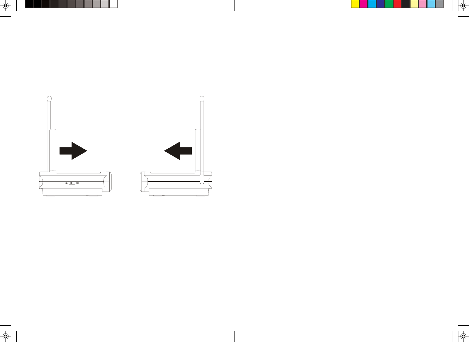
FINE TUNING YOUR SYSTEM
The Wireless Audio/Video Sender usually works best with the flat faces of
the antennas on the Sender and Receiver units facing each other, see
diagram below. Sometimes, however, reflections and other effects in your
home may affect the signal so that some adjustment of either the Sender or
Receiver antenna might be necessary to get the best signal.
If you are not getting any sound or picture at all from the Receiver:
• Check that the CHANNEL slide switch (labeled A, B, C, D) on both
units is set to the same letter. The switch is on the bottom of the Sender
and the Receiver units.
• Check that both the Sender’s and Receiver’s power supplies are
plugged in.
• Check that the ON/OFF switch on the Sender and Receiver are ON.
If the video or sound is poor, or there is interference:
Try changing the channel on both units. Do this by adjusting the
CHANNEL slide switch on each unit to any position from A to D. Make
sure both units are set to the same letter.

12
10.com, a division of X10 Wireless Technology, Inc.
3824 North 5th St., Suite C,
North Las Vegas, NV 89032
VK50A - 8/07