Automatic Technology KPX7201 Wireless Keypad User Manual

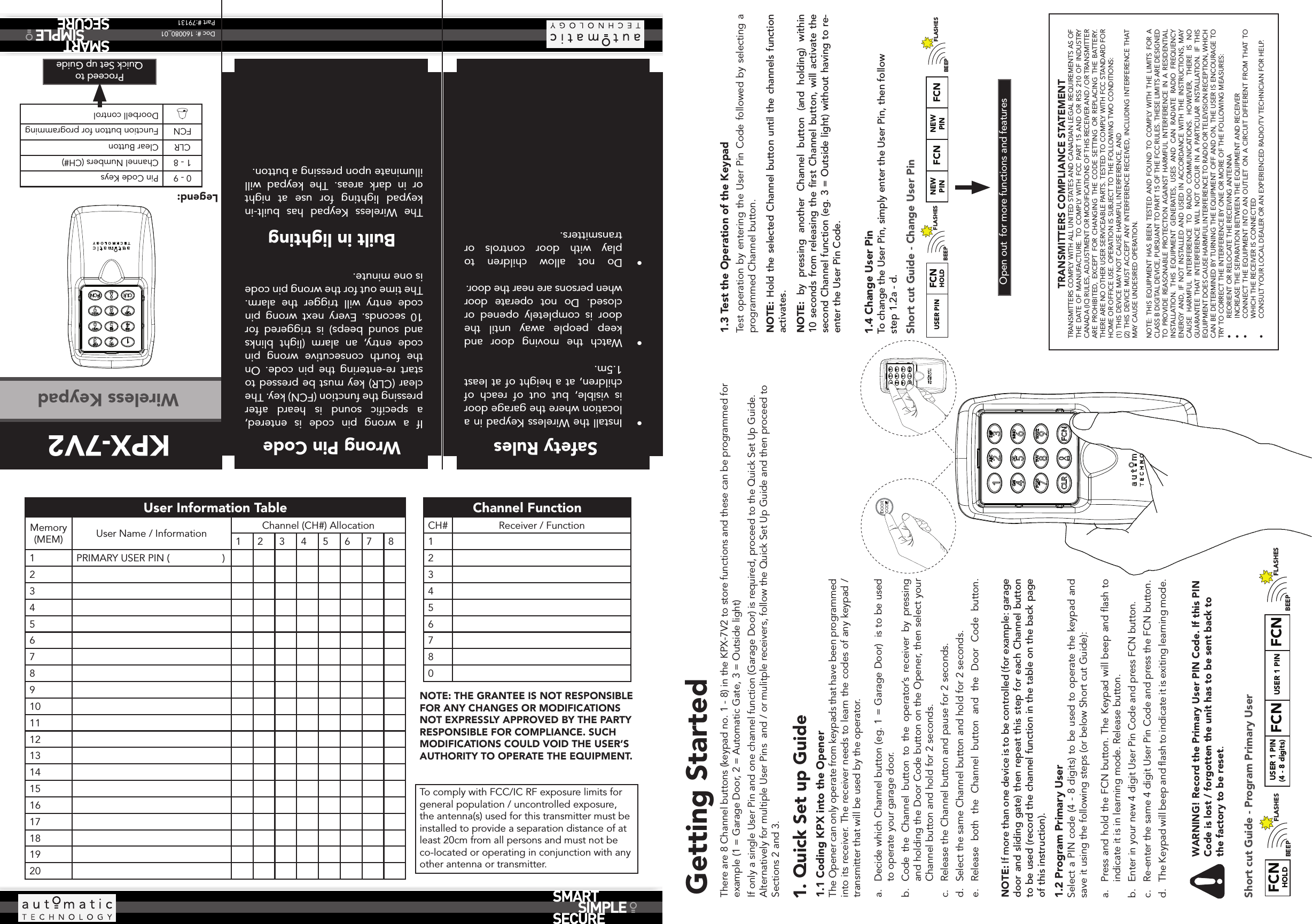
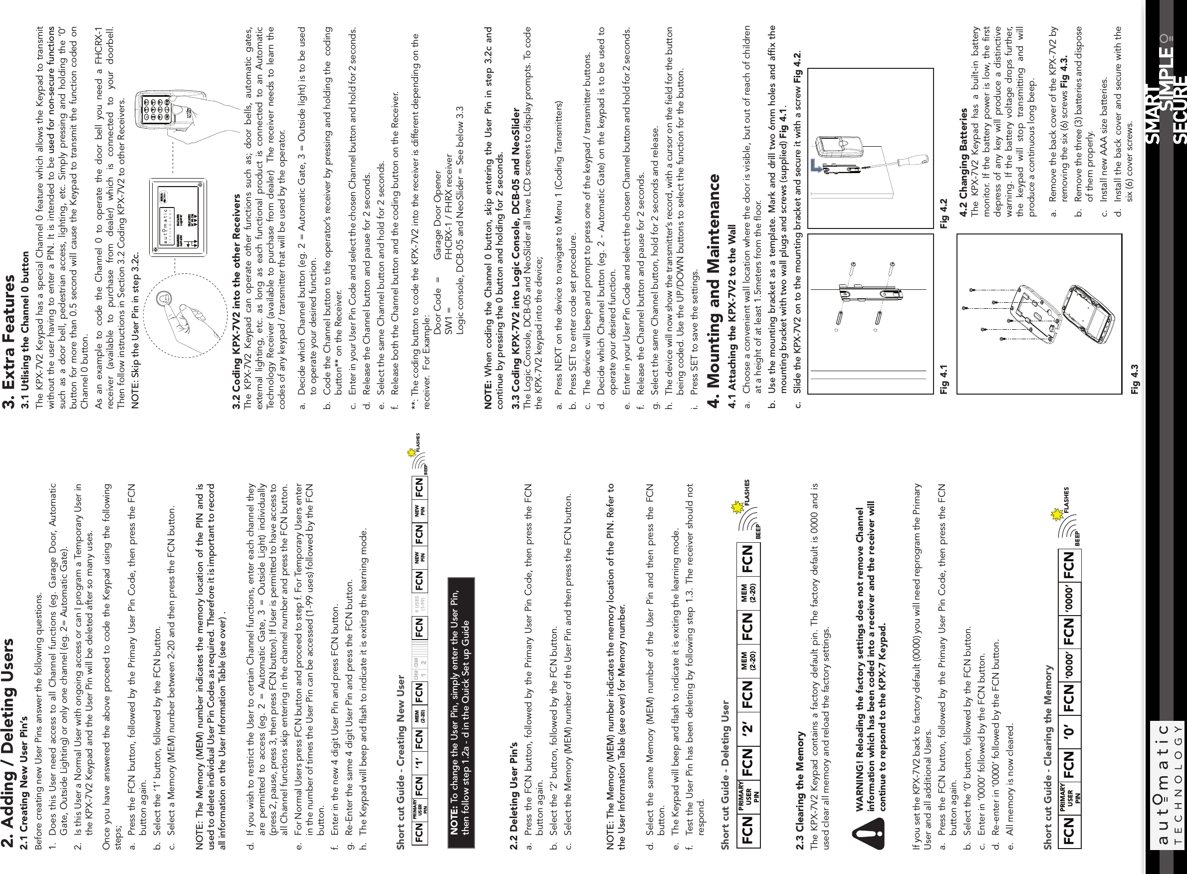
Automatic Technology (Australia) Pty. Ltd. Wireless Keypad

User Manual

Doc #: 160080_01Part #:79131KPX-7V2Wireless Keypad1.1 Coding KPX into the Opener The Opener can only operate from keypads that have been programmed into its receiver. The receiver needs to learn the codes of any keypad / transmitter that will be used by the operator.a.  Decide which Channel button (eg. 1 = Garage Door)  is to be used to operate your garage door. b.  Code the Channel button to the operator’s receiver by pressing and holding the Door Code button on the Opener, then select your Channel button and hold for 2 seconds.c.  Release the Channel button and pause for 2 seconds.  d.  Select the same Channel button and hold for 2 seconds.e.  Release both the Channel button and the Door Code button. NOTE: If more than one device is to be controlled (for example: garage door and sliding gate) then repeat this step for each Channel button to be used (record the channel function in the table on the back page of this instruction). Legend:0 - 9 Pin Code Keys1 - 8 Channel Numbers (CH#)CLR Clear ButtonFCN Function button for programmingDoorbell controlProceed to  Quick Set up GuideUser Information TableMemory (MEM) User Name / Information Channel (CH#) Allocation123456781 PRIMARY USER PIN (                   )234567891011121314151617181920Channel Function CH# Receiver / Function1234567801. Quick Set up GuideSafety Rules•  Install the Wireless Keypad in a location where the garage door is visible, but out of reach of children, at a height of at least 1.5m.•  Watch the moving door and keep people away until the door is completely opened or closed.  Do not operate door when persons are near the door.•  Do not allow children to play with door controls or transmitters.There are 8 Channel buttons (keypad no. 1 - 8) in the KPX-7V2 to store functions and these can be programmed for example (1 = Garage Door, 2 = Automatic Gate, 3 = Outside light)If only a single User Pin and one channel function (Garage Door) is required, proceed to the Quick Set Up Guide. Alternatively for multiple User Pins  and / or mulitple receivers, follow the Quick Set Up Guide and then proceed to  Sections 2 and 3. Getting Started1.2 Program Primary User  Select a PIN code (4 - 8 digits) to be used to operate the keypad and save it using the following steps (or below Short cut Guide):a.  Press and hold the FCN button. The Keypad will beep and flash to indicate it is in learning mode. Release button.b.  Enter in your new 4 digit User Pin Code and press FCN button.c.  Re-enter the same 4 digit User Pin Code and press the FCN button.d.  The Keypad will beep and flash to indicate it is exiting learning mode. WARNING! Record the Primary User PIN Code. If this PIN Code is lost / forgotten the unit has to be sent back to the factory to be reset. Short cut Guide - Program Primary UserOpen out  for more functions and features1.3 Test the Operation of the KeypadTest operation by entering the User Pin Code followed by selecting a programmed Channel button.NOTE: Hold the selected Channel button until the channels function activates.NOTE: by pressing another Channel button (and holding) within 10 seconds from releasing the first Channel button, will activate the second Channel function (eg. 3 = Outside light) without having to re-enter the User Pin Code.BEEPFCNHOLD USER 1 PIN(4 - 8 digits) FCN FCNFLASHES  USER 1 PINBEEPFLASHES USER PINBEEPFLASHES NEW PIN FCN NEW PIN FCNBEEPFLASHESFCNHOLDWrong Pin CodeIf a wrong pin code is entered, a specific sound is heard after pressing the function (FCN) key. The clear (CLR) key must be pressed to start re-entering the pin code. On the fourth consecutive wrong pin code entry, an alarm (light blinks and sound beeps) is triggered for 10 seconds. Every next wrong pin code entry will trigger the alarm. The time out for the wrong pin code is one minute.The Wireless Keypad has built-in keypad lighting for use at night or in dark areas. The keypad will illuminate upon pressing a button. Built in lightingTRANSMITTERS COMPLIANCE STATEMENTTRANSMITTERS COMPLY WITH ALL UNITED STATES AND CANADIAN LEGAL REQUIREMENTS AS OF THE DATE OF MANUFACTURE. TO COMPLY WITH FCC PART 15 AND OR RSS 210 OF INDUSTRY CANADA (IC) RULES, ADJUSTMENT OR MODIFICATIONS OF THIS RECEIVER AND / OR TRANSMITTER ARE PROHIBITED, EXCEPT FOR CHANGING THE CODE SETTING OR REPLACING THE BATTERY. THERE ARE NO OTHER USER SERVICEABLE PARTS. TESTED TO COMPLY WITH FCC STANDARD FOR HOME OR OFFICE USE. OPERATION IS SUBJECT TO THE FOLLOWING TWO CONDITIONS:(1) THIS DEVICE MAY NOT CAUSE HARMFUL INTERFERENCE, AND(2) THIS DEVICE MUST ACCEPT ANY INTERFERENCE RECEIVED, INCLUDING INTERFERENCE THAT MAY CAUSE UNDESIRED OPERATION.NOTE: THIS EQUIPMENT HAS BEEN TESTED AND FOUND TO COMPLY WITH THE LIMITS FOR A CLASS B DIGITAL DEVICE, PURSUANT TO PART 15 OF THE FCC RULES. THESE LIMITS ARE DESIGNED TO PROVIDE REASONABLE PROTECTION AGAINST HARMFUL INTERFERENCE IN A RESIDENTIAL INSTALLATION. THIS EQUIPMENT GENERATES, USES AND CAN RADIATE RADIO FREQUENCY ENERGY AND, IF NOT INSTALLED AND USED IN ACCORDANCE WITH THE INSTRUCTIONS, MAY CAUSE HARMFUL INTERFERENCE TO RADIO COMMUNICATIONS. HOWEVER, THERE IS NO GUARANTEE THAT INTERFERENCE WILL NOT OCCUR IN A PARTICULAR INSTALLATION. IF THIS EQUIPMENT DOES CAUSE HARMFUL INTERFERENCE TO RADIO OR TELEVISION RECEPTION, WHICH CAN BE DETERMINED BY TURNING THE EQUIPMENT OFF AND ON, THE USER IS ENCOURAGE TO TRY TO CORRECT THE INTERFERENCE BY ONE OR MORE OF THE FOLLOWING MEASURES:•  REORIENT OR RELOCATE THE RECEIVING ANTENNA•  INCREASE THE SEPARATION BETWEEN THE EQUIPMENT AND RECEIVER•  CONNECT THE EQUIPMENT INTO AN OUTLET ON A CIRCUIT DIFFERENT FROM THAT TO WHICH THE RECEIVER IS CONNECTED•  CONSULT YOUR LOCAL DEALER OR AN EXPERIENCED RADIO/TV TECHNICIAN FOR HELP.1.4 Change User Pin  To change the User Pin, simply enter the User Pin, then follow step 1.2a - d.Short cut Guide - Change User PinNOTE: THE GRANTEE IS NOT RESPONSIBLE FOR ANY CHANGES OR MODIFICATIONS NOT EXPRESSLY APPROVED BY THE PARTY RESPONSIBLE FOR COMPLIANCE. SUCH MODIFICATIONS COULD VOID THE USER’S AUTHORITY TO OPERATE THE EQUIPMENT.To comply with FCC/IC RF exposure limits for general population / uncontrolled exposure, the antenna(s) used for this transmitter must be installed to provide a separation distance of at least 20cm from all persons and must not be co-located or operating in conjunction with any other antenna or transmitter.
3. Extra Features3.1 Utlising the Channel 0 buttonThe KPX-7V2 Keypad has a special Channel 0 feature which allows the Keypad to transmit without the user having to enter a PIN. It is intended to be used for non-secure functions such as a door bell, pedestrian access, lighting, etc. Simply pressing and holding the ‘0’ button for more than 0.5 second will cause the Keypad to transmit the function coded on Channel 0 button.As an example to code the Channel 0 to operate the door bell you need a FHCRX-1 receiver (available to purchase from dealer) which is connected to your doorbell.   Then follow instructions in Section 3.2 Coding KPX-7V2 to other Receivers.NOTE: Skip the User Pin in step 3.2c.3.2 Coding KPX-7V2 into the other Receivers The KPX-7V2 Keypad can operate other functions such as; door bells, automatic gates, external lighting, etc. as long as each functional product is connected to an Automatic Technology Receiver (available to purchase from dealer)  The receiver needs to learn the codes of any keypad / transmitter that will be used by the operator.a.  Decide which Channel button (eg. 2 = Automatic Gate, 3 = Outside light) is to be used to operate your desired function. b.  Code the Channel button to the operator’s receiver by pressing and holding the  coding button** on the Receiver.c.  Enter in your User Pin Code and select the chosen Channel button and hold for 2 seconds.d.  Release the Channel button and pause for 2 seconds.  e.  Select the same Channel button and hold for 2 seconds.f.  Release both the Channel button and the coding button on the Receiver.**: The coding button to code the KPX-7V2 into the receiver is different depending on the receiver.  For Example:       Door Code  =   Garage Door Opener       SW1 =     FHCRX-1 / FHRX receiver        Logic console, DCB-05 and NeoSlider = See below 3.3      NOTE: When coding the Channel 0 button, skip entering the User Pin in step 3.2c and continue by pressing the 0 button and holding for 2 seconds. 3.3 Coding KPX-7V2 into Logic Console, DCB-05 and NeoSliderThe Logic Console, DCB-05 and NeoSlider all have LCD screens to display prompts. To code the KPX-7V2 keypad into the device;a.  Press NEXT on the device to navigate to Menu 1 (Coding Transmitters)b.  Press SET to enter code set procedure.c.  The device will beep and prompt to press one of the keypad / transmitter buttons.d.  Decide which Channel button (eg. 2 - Automatic Gate) on the keypad is to be used to operate your desired function.e.  Enter in your User Pin Code and select the chosen Channel button and hold for 2 seconds.f.  Release the Channel button and pause for 2 seconds.  g.  Select the same Channel button, hold for 2 seconds and release.h.  The device will now show the transmitter’s record, with a cursor on the field for the button being coded. Use the UP/DOWN buttons to select the function for the button. i.  Press SET to save the settings.2. Adding / Deleting Users2.3 Clearing the MemoryThe KPX-7V2 Keypad contains a factory default pin. The factory default is 0000 and is used clear all memory and reload the factory settings. WARNING! Reloading the factory settings does not remove Channel information which has been coded into a receiver and the receiver will continue to repsond to the KPX-7 Keypad.If you set the KPX-7V2 back to factory default (0000) you will need reprogram the Primary User and all additional Users.a.  Press the FCN button, followed by the Primary User Pin Code, then press the FCN button again.b.  Select the ‘0’ button, followed by the FCN button.c.  Enter in ‘0000’ followed by the FCN button.d.  Re-enter in ‘0000’ followed by the FCN button.e.  All memory is now cleared.Short cut Guide - Clearing the MemoryFHCRX-12.1 Creating New User Pin’sBefore creating new User Pins answer the following questions.1.  Does this User need access to all Channel functions (eg. Garage Door, Automatic Gate, Outside Lighting) or only one channel (eg. 2= Automatic Gate). 2.  Is this User a Normal User with ongoing access or can I program a Temporary User in the KPX-7V2 Keypad and the User Pin will be deleted after so many uses. Once you have answered the above proceed to code the Keypad using the following steps;a.  Press the FCN button, followed by the Primary User Pin Code, then press the FCN button again.b.  Select the ‘1’ button, followed by the FCN button.c.  Select a Memory (MEM) number between 2-20 and then press the FCN button.NOTE: The Memory (MEM) number indicates the memory location of the PIN and is used to delete individual User Pin Codes as required. Therefore it is important to record all information on the User Information Table (see over) .d.  If you wish to restrict the User to certain Channel functions, enter each channel they are permitted to access (eg. 2 = Automatic Gate, 3 = Outside Light) individually (press 2, pause, press 3, then press FCN button). If User is permitted to have access to all Channel functions skip entering in the channel number and press the FCN button.e.  For Normal Users press FCN button and proceed to step f. For Temporary Users enter in the number of times the User Pin can be accessed (1-99 uses) followed by the FCN button.f.  Enter in the new 4 digit User Pin and press FCN button.g.  Re-Enter the same 4 digit User Pin and press the FCN button.h.  The Keypad will beep and flash to indicate it is exiting the learning mode.Short cut Guide - Creating New UserNOTE: To change the User Pin, simply enter the User Pin, then follow step 1.2a - d in the Quick Set up Guide2.2 Deleting User Pin’sa.  Press the FCN button, followed by the Primary User Pin Code, then press the FCN button again.b.  Select the ‘2’ button, followed by the FCN button.c.  Select the Memory (MEM) number of the User Pin and then press the FCN button.NOTE: The Memory (MEM) number indicates the memory location of the PIN. Refer to the User Information Table (see over) for Memory number.d.  Select the same Memory (MEM) number of the User Pin and then press the FCN button.e.  The Keypad will beep and flash to indicate it is exiting the learning mode.f.  Test the User Pin has been deleting by following step 1.3. The receiver should not respond.Short cut Guide - Deleting UserBEEPFCN FCN ‘1’ FCN MEM (2-20) FCN CH#1FCN FLASHESCH#2NEWPIN FCN NEWPIN FCN# USES (1-99) PRIMARY USERPIN FCNBEEPFCN FCN ‘2’ FCN MEM (2-20) FCN FLASHESMEM (2-20) FCN PRIMARY USERPINBEEPFCN FCN ‘0’ FCN ‘0000’ FCN FCN FLASHES PRIMARY USERPIN‘0000’4. Mounting and Maintenance4.1 Attaching the KPX-7V2 to the Wall a.  Choose a convenient wall location where the door is visible, but out of reach of children at a height of at least 1.5meters from the floor.b.  Use the mounting bracket as a template. Mark and drill two 6mm holes and affix the mounting bracket with two wall plugs and screws (supplied) Fig 4.1.c.  Slide the KPX-7V2 on to the mounting bracket and secure it with a screw Fig 4.2. 4.2 Changing Batteries The KPX-7V2 Keypad has a built-in battery monitor. If the battery power is low, the first depress of any key will produce a distinctive warning. If the battery voltage drops further, the keypad will stop transmitting and will produce a continuous long beep.Fig 4.1 Fig 4.2a.  Remove the back cover of the KPX-7V2 by removing the six (6) screws Fig 4.3.b.  Remove the three (3) batteries and dispose of them properly.c.  Install new AAA size batteries.d.  Install the back cover and secure with the six (6) cover screws.Fig 4.3

Navigation menu