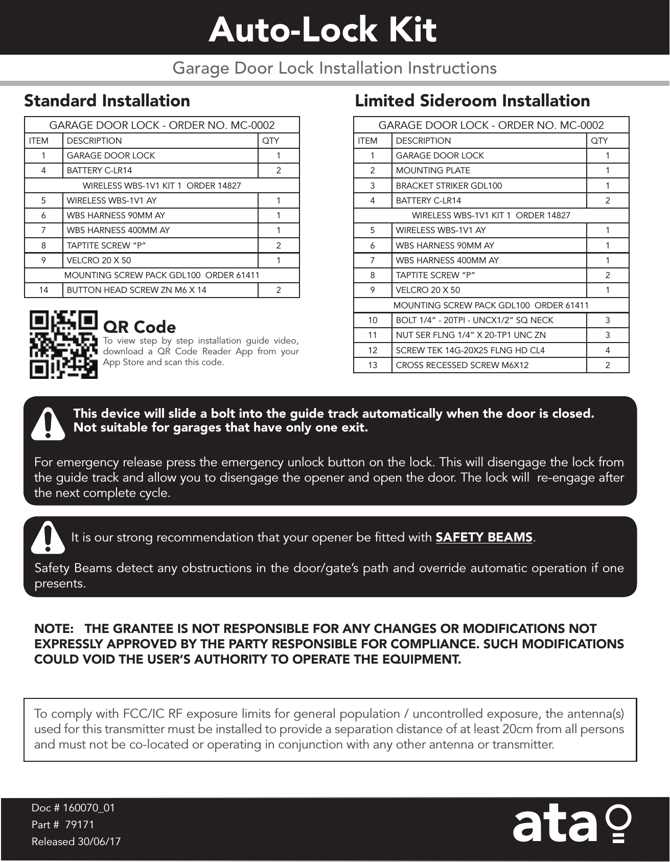
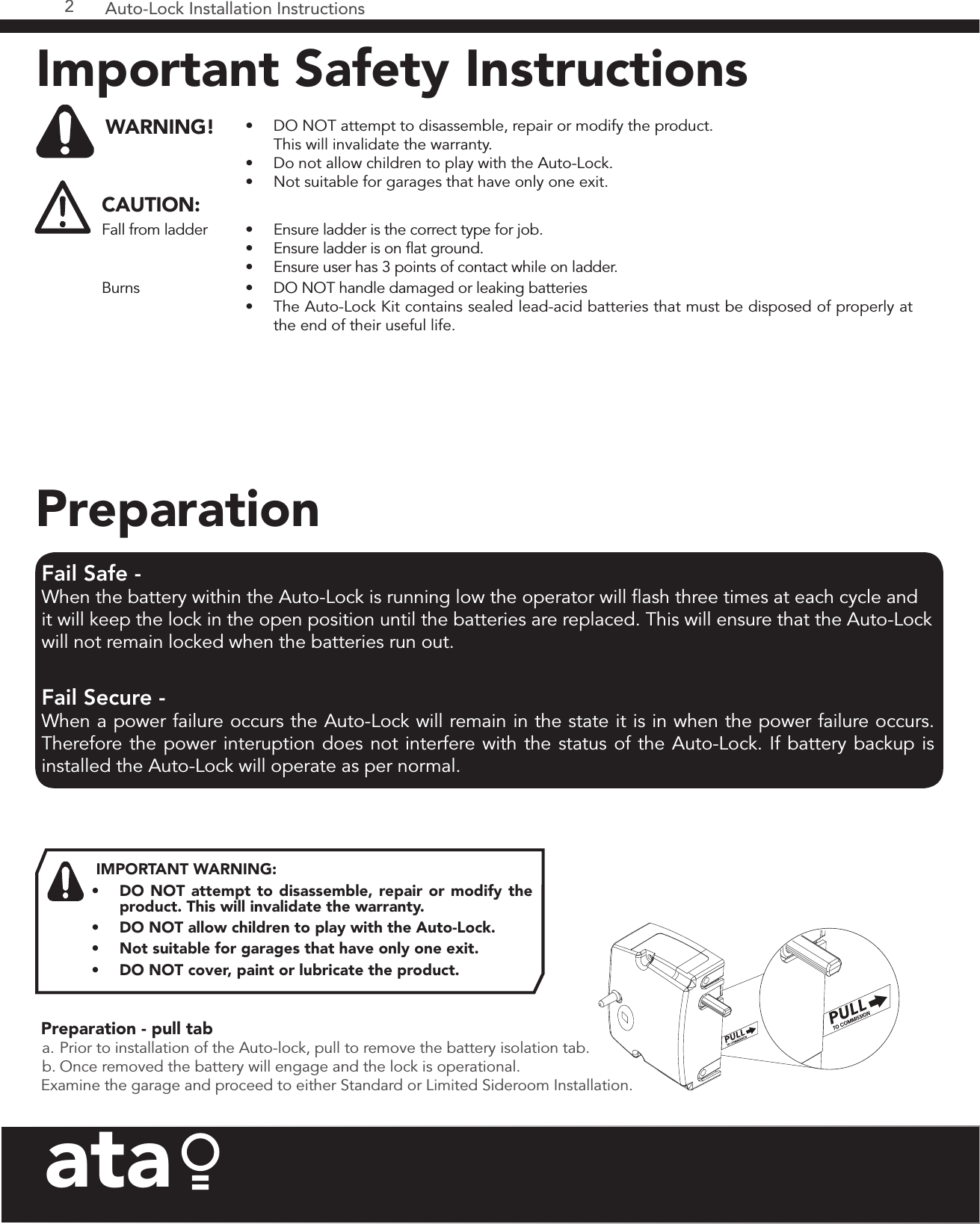
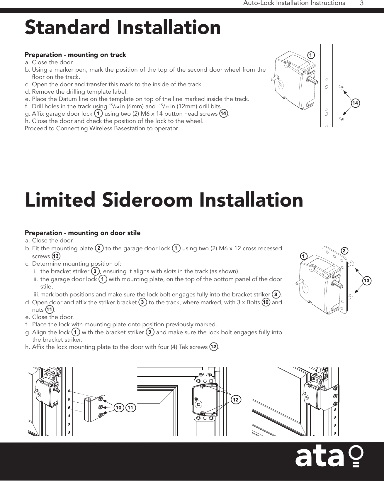
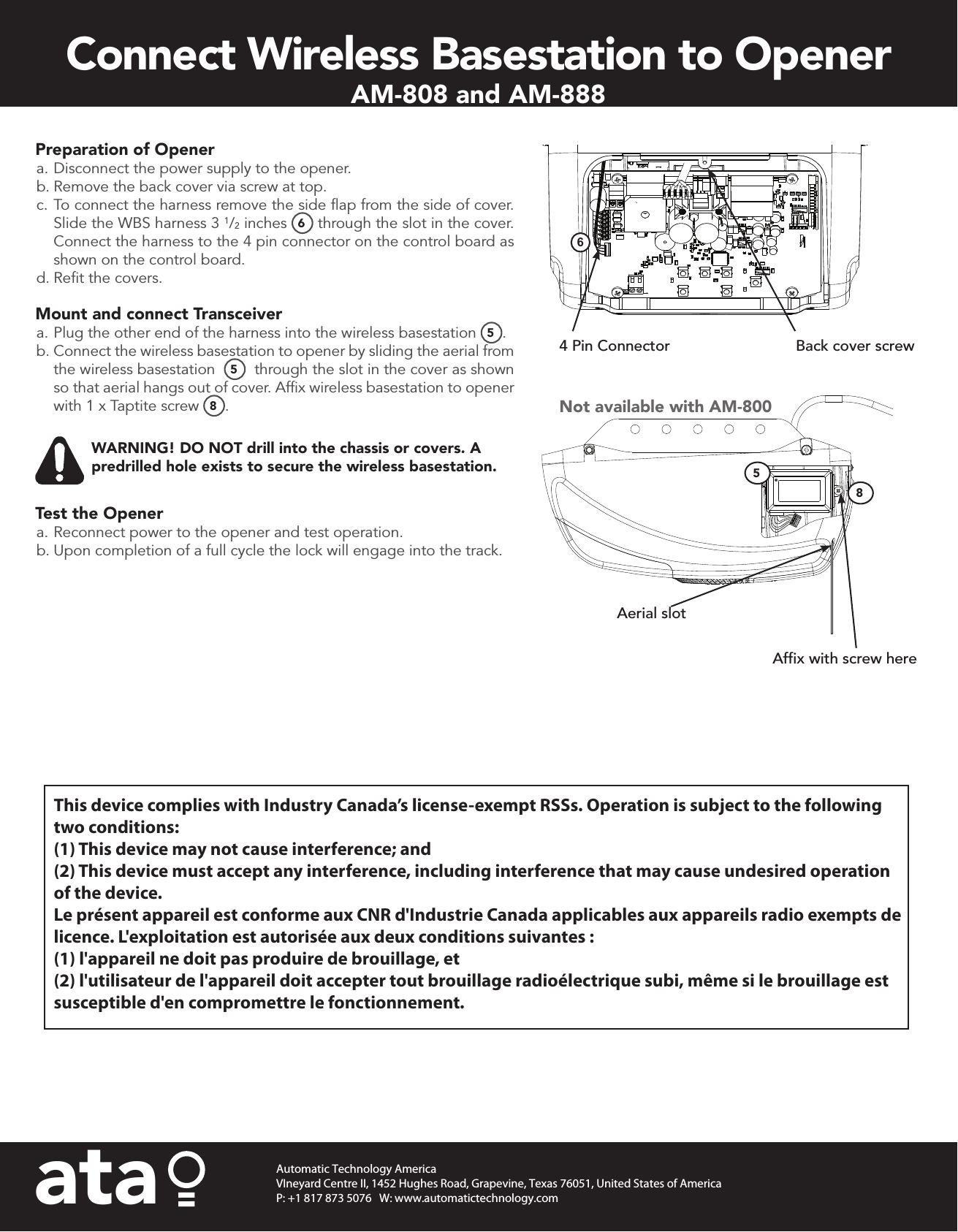
Automatic Technology WBSNT0102M2 WIRELESS WBS-1V2 TRANSCEIVER User Manual

Automatic Technology (Australia) Pty. Ltd. WIRELESS WBS-1V2 TRANSCEIVER

User Manual

Garage Door Lock Installation InstructionsAuto-Lock Kit Standard Installation GARAGE DOOR LOCK - ORDER NO. MC-0002ITEM DESCRIPTION QTY1 GARAGE DOOR LOCK 14 BATTERY C-LR14 2WIRELESS WBS-1V1 KIT 1  ORDER 148275 WIRELESS WBS-1V1 AY 16 WBS HARNESS 90MM AY 17 WBS HARNESS 400MM AY 18 TAPTITE SCREW “P” 29 VELCRO 20 X 50 1MOUNTING SCREW PACK GDL100  ORDER 6141114 BUTTON HEAD SCREW ZN M6 X 14 2Limited Sideroom InstallationGARAGE DOOR LOCK - ORDER NO. MC-0002ITEM DESCRIPTION QTY1 GARAGE DOOR LOCK 12 MOUNTING PLATE 13 BRACKET STRIKER GDL100 14 BATTERY C-LR14 2WIRELESS WBS-1V1 KIT 1  ORDER 148275 WIRELESS WBS-1V1 AY 16 WBS HARNESS 90MM AY 17 WBS HARNESS 400MM AY 18 TAPTITE SCREW “P” 29 VELCRO 20 X 50 1MOUNTING SCREW PACK GDL100  ORDER 6141110 BOLT 1/4” - 20TPI - UNCX1/2” SQ NECK 311 NUT SER FLNG 1/4” X 20-TP1 UNC ZN 312 SCREW TEK 14G-20X25 FLNG HD CL4  413 CROSS RECESSED SCREW M6X12 2 It is our strong recommendation that your opener be fitted with SAFETY BEAMS.  Safety Beams detect any obstructions in the door/gate’s path and override automatic operation if one presents.   This device will slide a bolt into the guide track automatically when the door is closed. Not suitable for garages that have only one exit.For emergency release press the emergency unlock button on the lock. This will disengage the lock from the guide track and allow you to disengage the opener and open the door. The lock will  re-engage after the next complete cycle.QR CodeTo view step by step installation guide video, download a QR Code Reader App from your App Store and scan this code.Doc # 160070_01Part #  79171Released 30/06/17ataTo comply with FCC/IC RF exposure limits for general population / uncontrolled exposure, the antenna(s) used for this transmitter must be installed to provide a separation distance of at least 20cm from all persons and must not be co-located or operating in conjunction with any other antenna or transmitter. NOTE:   THE GRANTEE IS NOT RESPONSIBLE FOR ANY CHANGES OR MODIFICATIONS NOT EXPRESSLY APPROVED BY THE PARTY RESPONSIBLE FOR COMPLIANCE. SUCH MODIFICATIONS COULD VOID THE USER’S AUTHORITY TO OPERATE THE EQUIPMENT.
Auto-Lock Installation Instructions2ataPreparation - pull tab a. Prior to installation of the Auto-lock, pull to remove the battery isolation tab.b. Once removed the battery will engage and the lock is operational.Examine the garage and proceed to either Standard or Limited Sideroom Installation.IMPORTANT WARNING: •  DO NOT attempt to disassemble, repair or modify the product. This will invalidate the warranty.  •  DO NOT allow children to play with the Auto-Lock.•  Not suitable for garages that have only one exit.•  DO NOT cover, paint or lubricate the product. Fail Safe - When the battery within the Auto-Lock is running low the operator will flash three times at each cycle and it will keep the lock in the open position until the batteries are replaced. This will ensure that the Auto-Lock will not remain locked when the batteries run out. Fail Secure - When a power failure occurs the Auto-Lock will remain in the state it is in when the power failure occurs. Therefore the power interuption does not interfere with the status of the Auto-Lock. If battery backup is installed the Auto-Lock will operate as per normal.PreparationImportant Safety Instructions WARNING! •  DO NOT attempt to disassemble, repair or modify the product.  This will invalidate the warranty.•  Do not allow children to play with the Auto-Lock.•  Not suitable for garages that have only one exit.CAUTION:Fall from ladder •  Ensure ladder is the correct type for job.•  Ensure ladder is on flat ground.•  Ensure user has 3 points of contact while on ladder.Burns •  DO NOT handle damaged or leaking batteries•  The Auto-Lock Kit contains sealed lead-acid batteries that must be disposed of properly at the end of their useful life.
3Auto-Lock Installation Instructionsata Preparation - mounting on track  a. Close the door.b. Using a marker pen, mark the position of the top of the second door wheel from the floor on the track.c. Open the door and transfer this mark to the inside of the track.d. Remove the drilling template label.e. Place the Datum line on the template on top of the line marked inside the track.f.  Drill holes in the track using 15/64 in (6mm) and  15/32 in (12mm) drill bits.g. Affix garage door lock  1 using two (2) M6 x 14 button head screws  14 .h. Close the door and check the position of the lock to the wheel.Proceed to Connecting Wireless Basestation to operator.114 Preparation - mounting on door stile  a. Close the door.b. Fit the mounting plate  2 to the garage door lock  1 using two (2) M6 x 12 cross recessed screws  13 .c. Determine mounting position of:i.  the bracket striker  3, ensuring it aligns with slots in the track (as shown).ii. the garage door lock  1 with mounting plate, on the top of the bottom panel of the door stile, iii. mark both positions and make sure the lock bolt engages fully into the bracket striker  3.d. Open door and affix the striker bracket  3 to the track, where marked, with 3 x Bolts  10  and nuts  11 .e. Close the door.f.  Place the lock with mounting plate onto position previously marked.g. Align the lock  1 with the bracket striker  3 and make sure the lock bolt engages fully into the bracket striker.  h. Affix the lock mounting plate to the door with four (4) Tek screws  12 .131210 1112Standard InstallationLimited Sideroom Installation
ataAutomatic Technology AmericaVIneyard Centre II, 1452 Hughes Road, Grapevine, Texas 76051, United States of AmericaP: +1 817 873 5076   W: www.automatictechnology.comPreparation of Opener a. Disconnect the power supply to the opener.b. Remove the back cover via screw at top.c. To connect the harness remove the side flap from the side of cover. Slide the WBS harness 3 1/2 inches  6 through the slot in the cover. Connect the harness to the 4 pin connector on the control board as shown on the control board.d. Refit the covers.Mount and connect Transceivera. Plug the other end of the harness into the wireless basestation 5.b. Connect the wireless basestation to opener by sliding the aerial from the wireless basestation   5  through the slot in the cover as shown so that aerial hangs out of cover. Affix wireless basestation to opener with 1 x Taptite screw  8.WARNING! DO NOT drill into the chassis or covers. A predrilled hole exists to secure the wireless basestation.Test the Openera. Reconnect power to the opener and test operation.b. Upon completion of a full cycle the lock will engage into the track.Back cover screw4 Pin Connector6Aerial slotAffix with screw hereNot available with AM-800Connect Wireless Basestation to Opener AM-808 and AM-88885This device complies with Industry Canada’s license-exempt RSSs. Operation is subject to the following two conditions:(1) This device may not cause interference; and (2) This device must accept any interference, including interference that may cause undesired operation of the device.Le présent appareil est conforme aux CNR d'Industrie Canada applicables aux appareils radio exempts de licence. L'exploitation est autorisée aux deux conditions suivantes : (1) l'appareil ne doit pas produire de brouillage, et (2) l'utilisateur de l'appareil doit accepter tout brouillage radioélectrique subi, même si le brouillage est susceptible d'en compromettre le fonctionnement.

Navigation menu