Avalan Wireless Systems orporated AW900G2HP MOD090-HP User Manual
Avalan Wireless Systems Incorporated MOD090-HP
User Manual
USER’S MANUAL
Industrial-grade, long-range wireless Ethernet systems
900 MHz High Power Module
MOD090-HP

MOD090-HP User’s Manual
PAGE 2
Technical support (650) 384-0000 www.avalanwireless.com
© 2017 by AvaLAN Wireless Systems Inc. All rights reserved.
Revision 02.09.2017
127 Jetplex Circle
Madison, AL 35758
Sales: (866) 533-6216
Technical Support: (650) 384-0000
Customer Service: (650) 641-3011
Fax: (650) 249-3591
Thank you for your purchase of the MOD090-HP 900 MHz Radio Module.
Firmware and software described in this manual may be downloaded from
www.avalanwireless.com/downloads.htm. (You can also nd a pdf of the latest
version of this manual.)
If you have any questions when conguring your AvaLAN system, the best place to
get answers is to visit www.avalanwireless.com. If more assistance is needed, send
email to support@avalanwireless.com. To speak to a live technician, please call
technical support at the number below during normal business hours.

PAGE 3
Technical support (650) 384-0000 www.avalanwireless.com
MOD090-HP
User’s Manual
Table of Contents
Technical Summary . . . . . . . . . . . . . . . . . . . . . . . 4
Module Physical Interface . . . . . . . . . . . . . . . . . . 5
Module SPI Interfaces . . . . . . . . . . . . . . . . . . . . . 5
Module UART Interface . . . . . . . . . . . . . . . . . . . . . 11
Module Command Set . . . . . . . . . . . . . . . . . . . . . 12
Programming Examples . . . . . . . . . . . . . . . . . . . . 25
Implementation Block Diagrams . . . . . . . . . . . . . . 28
FCC and IC Certication . . . . . . . . . . . . . . . . . . . . . 30

MOD090-HP User’s Manual
PAGE 4
Technical support (650) 384-0000 www.avalanwireless.com
Technical Summary
The MOD090 module allows you to build your own extreme-range, non-line-of-
sight, point-to-multipoint wireless solution. The module uses the new technology in
our 900Mhz and is fully FCC/IC certied for quick integration with no RF retesting
required.
The MOD090 solution offers the ideal combination of the maximum allowed transmit
power and unbeatable interference immunity in conjunction with high throughput
and validated encryption.
The host microcontroller is responsible for conguring the keys that the MOD090-HP
uses for RF communication/encryption, as well as transferring data to and from the
MOD090-HP. The MOD090-HP features an 8kB transmit FIFO and a 5kB receive FIFO.
The RF communication topology that the modules use is a point to multipoint star
topology. There is one RF master Access Point (AP) and up to 63 RF slave Subscriber
Units (SU).
Data from the AP can be sent to one specic SU or broadcast to all SUs. Broadcast
data has no retransmissions and is not guaranteed to reach all SUs. Data from an SU
is always sent to the AP with retransmissions.
Data is divided up into blocks for RF transmission. This division of the data allows
for better interference immunity and re-transmission performance.
The digital interface to the MOD090-HP may be SPI or UART, depending upon which
rmware is running in the MOD090-HP.
Serial Peripheral Interface (SPI) is a full duplex synchronous serial interface. SPI is
a master-slave interface, with the master providing the synchronous clock.
Universal Asynchronous Receiver/Transmitter (UART) is an asynchronous serial
interface that allows data to be transmitted without a clock signal, but the sender
and receiver of the data must agree in advance on the timing parameters and spe-
cial bits are added to each data byte to synchronize the sending and receiving units.
Selecting SPI or UART:
The choice of interface is up to the user and governed by the user's application and
the nature of the host microcontroller. UART is more common, being closely related
to RS-232. It is also places fewer demands on the host microcontroller. The UART
interface is limited to 115,200 bits per second, while SPI may be run as high as 12
megabits per second. Whether the MOD090-HP uses SPI or UART is a choice that is
controlled at boot up. By connecting a 10K resistor from Pin 8 (Error Flag) to Vcc
(pull up), the MOD090-HP will boot up in UART mode. If the resistor is connected
instead to ground (pull down), it will boot up in SPI mode.
PAGE 5
Technical support (650) 384-0000 www.avalanwireless.com
MOD090-HP
User’s Manual
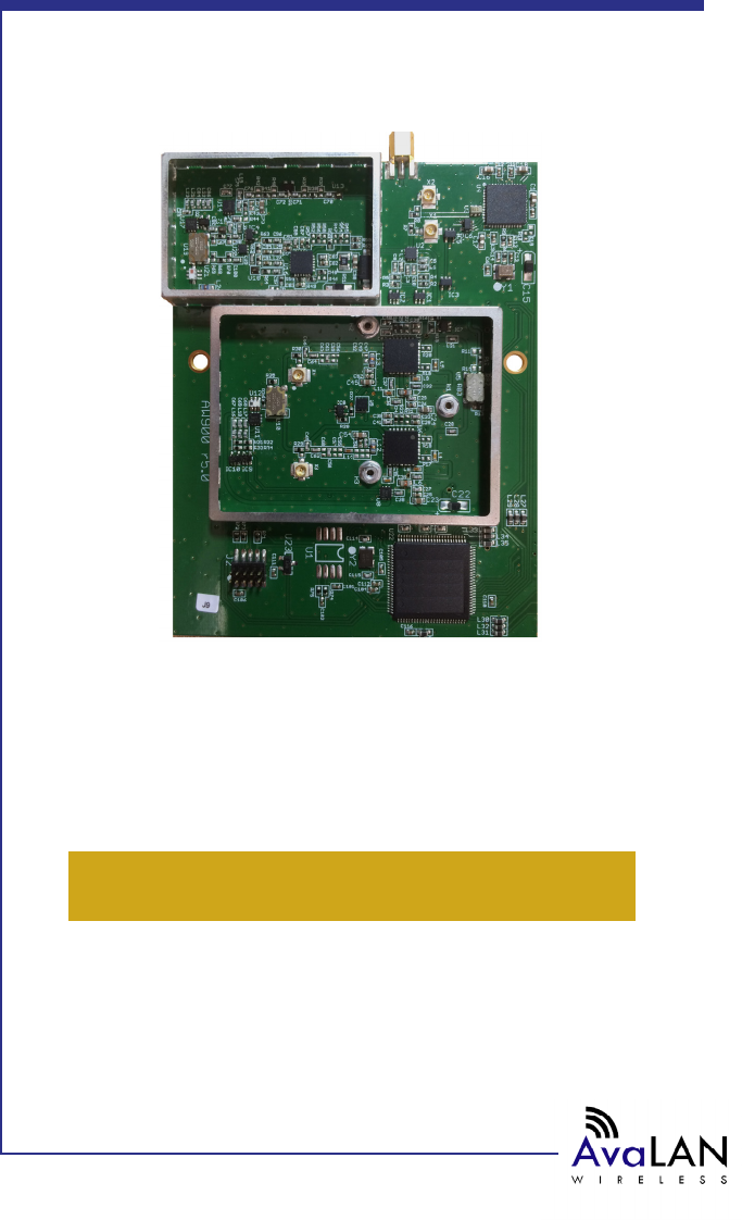
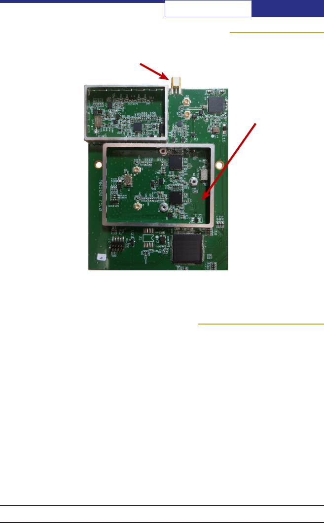
Module Physical Interface
RF Antenna
MMCX
Module SPI Interfaces
Serial Peripheral Interface (SPI) is a full duplex synchronus serial interface that
allows data to be shifted in and out of the AvaLAN Baseband Processor (MOD090-HP)
8 bits at a time, most signicant bit rst.
Each SPI requires 4 pins to be physically connected:
• SCK – Serial bit shift clock (provided by master SPI)
• MISO – Master In Slave Out
• MOSI – Master Out Slave In
• CS – Active low Chip Select
There are two SPI interfaces on the MOD090-HP. The rst is a master SPI (SPI0),
operating LEDs and DIP switches. SPI0’s connections are pins 3-6. The second is a
slave SPI (SPI1) for management of the radio link, statistics, rmware upgrading,
and data transfers. SPI1’s connections are on pins 12-15.
RF Section
MOD090-HP User’s Manual
PAGE 6
Technical support (650) 384-0000 www.avalanwireless.com
Here are the Signal denitions for the AW900SPI in SPI mode:
Pin Number Name Description
1Vcc 3.3 vdc for MOD090-HP
2/CS_LED Chip select for LEDs and DIP switches (active low)C
3/CS_PD Chip select for external programming devicehip s
4SCK0 Serial clock for LEDs and DIP switches
5MISO0 Data in for LEDs and DIP switches
6MOSI0 Data out for LEDs and DIP switches
7GND MOD090-HP Ground
8Error Flag 1=last command not understood. Clear with /CS_BB
9Data Ready 1=data packet available, 0=no data
10 FIFO Full Flag 1=FIFO full, don’t send any more data, 0=FIFO is empty
11 Connected Flag 1=RF connection present, 0=RF searching/standby
12 /CS_BB Chip select for MOD090-HP
13 SCK1 Serial clock for MOD090-HP
14 MOSI1 Data out for MOD090-HP
15 MISO1 Data in for MOD090-HP
16 RFVcc 3.3 vdc for RF section
17 RFGND RF section ground
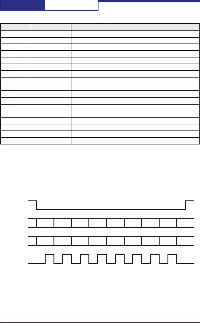
SPI0 uses mode (0,0) for clock phase and polarity. This means that the SCK0 line
idles low and data is setup on the falling edge of the clock and latched on the rising
edge. SPI1 uses mode (1,1), meaning that SCK1, MISO1 and MOSI1 are all idle high.
Data is still set up on the falling edge and latched on the rising edge of the clock.
CS
MISO b7 b6 b5 b4 b3 b2 b1 b0
MOSI b7 b6 b5 b4 b3 b2 b1 b0
SCK
PAGE 7
Technical support (650) 384-0000 www.avalanwireless.com
MOD090-HP
User’s Manual
SPI0 - LEDs and DIP Switches
SPI0 is a master mode SPI that sends out 4 bytes per transaction. The rst two bytes
are alignment bytes and the last two contain the LED data on MOSI0, and the DIP
switch data on MISO0.
The rst alignment byte is 0x55, and the second is 0xAA. These two bytes are used
to determine the start of the transaction (0x55) and the start of the data (0xAA).
LEDs:
/CS_LED
MISO0 XX XX Byte3 Byte4
MOSI0 0x55 0xAA Byte3 Byte4
SCK0
A bit that is set in either of these bytes indicates that the corresponding LED should
be on.
Byte3 b7 b6 b5 b4 b3 b2 b1 b0
PWR RX_
ACT
LCH5 LCH4 LCH3 LCH2 LCH1 LCH0
PWR: Turns on when the rmware is running. In troubleshoot mode PWR changes
states on the AP every time a search for more SUs takes place. On a SU PWR chang-
es state every time the SU responds to a search for more SUs.
RX_ACT: Indicates when data trafc has been received by the RF. RX_ACT will be
set for 32ms when data has been successfully received.
LCH5..0: Indicates what RF channel is currently in use. In troubleshoot mode these
bits indicate what the unit’s device ID is.
Byte4 b7 b6 b5 b4 b3 b2 b1 b0
TX_
ACT
-RFQ5 RFQ4 RFQ3 RFQ2 RFQ1 RFQ0

MOD090-HP User’s Manual
PAGE 8
Technical support (650) 384-0000 www.avalanwireless.com
TX_ACT: Indicates when data trafc is queued up for transmission across the RF.
TX_ACT will be set for 32ms when data is queued up for transmission.
RFQ5..0: Indicates the quality of the RF link. The lowest quality is only b0 set, the
highest quality is reached when b5 is set.
DIPs:
A bit that is set in this byte indicates that the corresponding DIP switch is on.
Byte3 b7 b6 b5 b4 b3 b2 b1 b0
DCH5 DCH4 DCH3 DCH2 DCH1 DCH0 MODE -
DCH5..0: Used to set the radio into manual channel mode and use the channel indi-
cated. If DCH5..0 are all clear then the radio will be in automatic mode.
MODE: When set the unit is in troubleshooting mode, when clear the unit is in
normal operation.
SPI1 – Command Interface
SPI1 is a slave mode SPI, meaning SCK is supplied by an external source. This SPI
is used to congure the module, read status information, issue rmware upgrades
and transfer data.
The rst byte on the MOSI line after the /CS_BB line goes low is the Command Byte.
This byte tells the MOD090-HP what command is to be executed.
Command Byte:
b7 b6 b5 b4 b3 b2 b1 b0
get/set - - - CMD3 CMD2 CMD1 CMD0
get/set: When set this bit indicates that information will be sent to the MOD090-HP
on MOSI1 and MISO1 will be high impedance. When clear a get transaction will take
place and information will be sent from the MOD090-HP on MISO1.
After the command byte is issued the master microcontroller must delay for at least
4 µs to allow the MOD090-HP enough time to prepare for the transaction.
When a transaction is complete and the /CS_BB line is high, the master
microcontroller must delay for at least 6 µs to allow the MOD090-HP to nish
processing the transaction.
CMD3..1: These bits are used to tell the MOD090-HP what command is to be
executed.
PAGE 9
Technical support (650) 384-0000 www.avalanwireless.com
MOD090-HP
User’s Manual
Module UART Interface
Here are the Signal denitions for the AW900SPI in UART mode:
Pin Number Name Description
1Vcc 3.3 vdc for MOD090-HP
2/CS_LED Chip select for external programming device
3/CS_PD Chip select for LEDs and DIP switches (active low)Chip s
4SCK0 Serial clock for LEDs and DIP switches
5MISO0 Data in for LEDs and DIP switches
6MOSI0 Data out for LEDs and DIP switches
7GND MOD090-HP Ground
8NC Not Used
9NC Not Used
10 NC Not Used
11 NC Not Used
12 NC Not Used
13 NC Not Used
14 MOSI1 UART TX
15 MISO1 UART RX
16 RFVcc 3.3 vdc for RF section
17 RFGND RF section ground
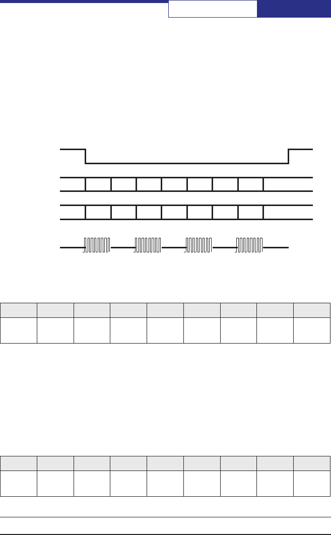
In UART mode, the MOD090-HP's command interface is moved to SPI0. The LEDs and
DIP switches may still be employed, but the primary purpose of this SPI port has
shifted. SPI1 now becomes an asynchronous UART with TX on pin 14 and RX on pin
15 and is used for data that is transmitted and received via the RF.
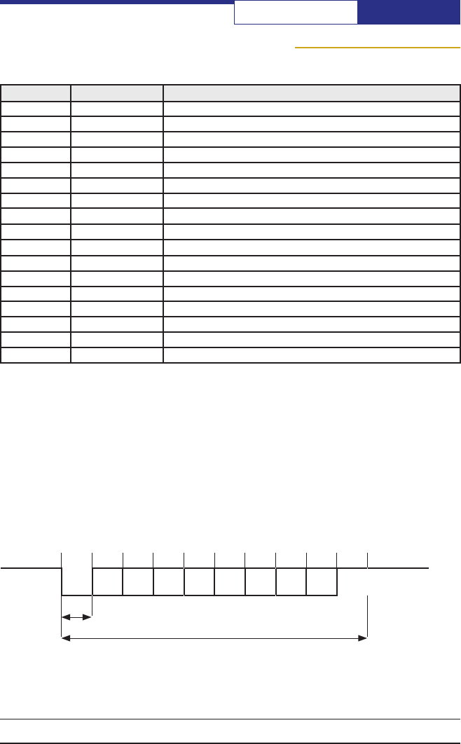
At the risk of belaboring what is obvious and familiar to most engineers because
of the long history of RS-232, the UART signals consist of a set of bits sent with a
pre-dened clock rate. The sender must agree on what the rate is, and because the
sender’s clock and receiver’s clock may not exactly agree, synchronization informa-
tion is sent with each byte of data:
Start
Bit D0D1D2D3D4D5D6D7Stop
Bit
TBaud Rate = 1/T
Single byte transmission (8 bits + Start + Stop)
The Stop Bit can actually be any duration and provides the variable delay that
allows synchronization between sender and receiver. Sometimes, the Stop Bit is
specied to be at least two intervals. Also, sometimes a Parity Bit is sent between
t0t1t2t3t4t5t6t7t8t9t10
Mark
Space

MOD090-HP User’s Manual
PAGE 10
Technical support (650) 384-0000 www.avalanwireless.com
D7 and the Stop Bit, but this is rarely done anymore.
UART Mode LEDs and DIPs:
With the UART rmware running, the LED denitions are the same as for SPI mode
and provide diagnostic information if desired.
The DIP switch denitions are slightly different:
b7 b6 b5 b4 b3 b2 b1 b0
Byte3 DCH3 DCH2 DCH1 DCH0 MODE -
Byte4 TEST
MODE: 1 = Access Point, 0 = Subscriber Unit
DCH3 to DCH0: 4-bit binary code for the RF channel selected. (All zeros means use
automatic channel switching.)
TEST: 1 = Continuous trafc for site survey testing, 0 = normal operation.

PAGE 11
Technical support (650) 384-0000 www.avalanwireless.com
MOD090-HP
User’s Manual
The Command Sets for SPI and UART modes are somewhat different:
SPI Command Set
Command Byte - HEX Command
0x01 getStatus
0x02 getNetworkKey
0x03 getPrivateKey
0x04 getDeviceID
0x05 getStats
0x06 getVersion
0x07 not valid
0x08 getNumberofConnectedSUs
0x09 getRSSIreadings
0x0A getDATAPacket
0x81 setStatus
0x82 setPublicKey
0x83 setPrivateKey
0x84 setDeviceID
0x85 setReset
0x86 not valid
0x87 not valid
0x88 not valid
0x89 not valid
0x8A setDATAPacket
0x8B setFirmwareStart
0x8C setFirmwareEnd
Module Command Set

MOD090-HP User’s Manual
PAGE 12
Technical support (650) 384-0000 www.avalanwireless.com
UART Command Set
Command Byte - HEX Command
0x00 getStatus
0x01 getNetworkKey
0x02 getPrivateKey
0x03 getDeviceID
0x04 getStats
0x05 getVersion
0x06 getCong
0x07 getNumberofConnectedSUs
0x08 getRSSIreadings
0x09 not valid
0x80 setStatus
0x81 setPublicKey
0x82 setPrivateKey
0x83 setDeviceID
0x84 setReset
0x85 not valid
0x86 not valid
0x87 not valid
0x89 not valid
0x8B setDATAPacket
In the Command Descriptions that follow, the command codes for each mode are
shown in the byte tables.
Status Command
The getStatus command is used to nd out the current status of the module.
getStatus SPI Mode: 0x01 UART Mode: 0x00
Byte 1 b7 b6 b5 b4 b3 b2 b1 b0
RFState Radio - - CH3 CH2 CH1 CH0

PAGE 13
Technical support (650) 384-0000 www.avalanwireless.com
MOD090-HP
User’s Manual
RFState: When set this bit indicates that the RF is currently connected.
Radio: Indicates what mode the radio is in, when set it is in active mode. When
clear the RF is in standby mode.
CH3..0: Indicates what channel the RF is currently using.
The setStatus command is used to place the module in standby mode/normal
operation and to set the RF into manual channel mode by assigning a specic
channel.
setStatus SPI Mode: 0x81 UART Mode: 0x80
Byte 1 b7 b6 b5 b4 b3 b2 b1 b0
-Radio - - CH3 CH2 CH1 CH0
Radio: Setting this bit places the radio in active mode, clearing it places it in
standby mode.
CH3..0: When these bits are cleared the radio is in automatic channel mode. When
any of these bits are set the radio will be in manual channel mode and use the
channel indicated by these bits if it is valid.
Channel Frequency - MHz
1904.4
2905.6
3906.8
4908.0
5909.2
6910.4
7911.6
8912.8
9914.0
10 915.2
11 916.4
12 917.6
13 918.8
14 920.0
15 921.2
16 922.4
17 923.6
18 924.8
19 926.0

MOD090-HP User’s Manual
PAGE 14
Technical support (650) 384-0000 www.avalanwireless.com
Network Key Command
The Network Key is A 32-bit number used for Network Identication. AvaLAN m-
series devices with different Network Keys will not be able to communicate with
each other. The Network Key can be changed without resetting the device.
The getNetworkKey command will read back the last 32-bit key issued to the
device.
The setNetworkKey command stores a new 32-bit key to be used for RF
communications.
getNetworkKey SPI Mode: 0x02 UART Mode: 0x01
setNetworkKey SPI Mode: 0x82 UART Mode: 0x81
b7 b6 b5 b4 b3 b2 b1 b0
Byte 1 PK7 PK6 PK5 PK4 PK3 PK2 PK1 PK0
Byte 2 PK15 PK14 PK13 PK12 PK11 PK10 PK9 PK8
Byte 3 PK23 PK22 PK21 PK20 PK19 PK18 PK17 PK16
Byte 4 PK31 PK30 PK29 PK28 PK27 PK26 PK25 PK24
Private Key Command
The Private Key is the 128-bit key used in the AES encryption of data transmitted
over the RF. This key must be set once at start up and cannot be changed without
resetting the device. If two or more radios have the same Public Key but different
Private Keys, they will connect with each other. However, the received data will be
completely scrambled.
The getPrivateKey command reads back the private key issued at startup.
The setPrivateKey command stores the private key to be used for the AES encryp-
tion. This command should be issued only once at start up. If issued again with a
different key, data corruption will occur.
getPrivateKey SPI Mode: 0x03 UART Mode: 0x02
setPrivateKey SPI Mode: 0x83 UART Mode: 0x82
b7 b6 b5 b4 b3 b2 b1 b0
Byte 1 SK7 SK6 SK5 SK4 SK3 SK2 SK1 SK0
Byte 2 SK15 SK14 SK13 SK12 SK11 SK10 SK9 SK8

PAGE 15
Technical support (650) 384-0000 www.avalanwireless.com
MOD090-HP
User’s Manual
Byte 3 SK23 SK22 SK21 SK20 SK19 SK18 SK17 SK16
Byte 4 SK31 SK30 SK29 SK28 SK27 SK26 SK25 SK24
Byte 5 SK39 SK38 SK37 SK36 SK35 SK34 SK33 SK32
Byte 6 SK47 SK46 SK45 SK44 SK43 SK42 SK41 SK40
Byte 7 SK55 SK54 SK53 SK52 SK51 SK50 SK49 SK48
Byte 8 SK63 SK62 SK61 SK60 SK59 SK58 SK57 SK56
Byte 9 SK71 SK70 SK69 SK68 SK67 SK66 SK65 SK64
Byte 10 SK79 SK78 SK77 SK76 SK75 SK74 SK73 SK72
Byte 11 SK87 SK86 SK85 SK84 SK83 SK82 SK81 SK80
Byte 12 SK95 SK94 SK93 SK92 SK91 SK90 SK89 SK88
Byte 13 SK103 SK102 SK101 SK100 SK99 SK98 SK97 SK96
Byte 14 SK111 SK110 SK109 SK108 SK107 SK106 SK105 SK104
Byte 15 SK119 SK118 SK117 SK116 SK115 SK114 SK113 SK112
Byte 16 SK127 SK126 SK125 SK124 SK123 SK122 SK121 SK120
Device ID Command
The Device ID command has two uses depending on whether the device is cong-
ured as an access point (AP) or subscriber unit (SU.) In either case, the Device ID is
a 6-bit number, allowing a maximum ID of 63. The Device ID must be issued at start
up and must not be changed without resetting the device.
For the AP the Device ID is the maximum SU ID that is allowed to connect to the RF
network.
For the SU the Device ID is the individual ID number assigned to the device. This ID
number is used as an address during data transfers.
The getDeviceID command reads back the congured ID.
The setDeviceID command congures the device to be either an AP or an SU and
what ID to use.
getDeviceID SPI Mode: 0x04 UART Mode: 0x03
setDeviceID SPI Mode: 0x84 UART Mode: 0x83
b7 b6 b5 b4 b3 b2 b1 b0
Byte 1 D1 D0 MID5 MID4 MID3 MID2 MID1 MID0

MOD090-HP User’s Manual
PAGE 16
Technical support (650) 384-0000 www.avalanwireless.com
D1, D0: These bits report or congure whether the device is an AP or an SU:
D1 D0 Mode
0 0 Not Congured
0 1 AP
1 0 AP
1 1 SU
MID5..0: These bits read back or set the congured ID. For an AP this is the maxi-
mum ID number that is allowed to join the RF network. For an SU it is the number
to use to join the RF network.
Stats Command
The getStats command is used to gather all the statistics that the MOD090-HP is
collecting about the RF link. The statistics are, total number of packets transferred,
total number of packets that failed to make it across the RF, total number of packets
that successfully made it across the RF, total number of broadcast packets, total
number of unicast packets, average transmitted packet size in the last 32 packets,
average received packet size in the last 32 packets, and percentage block error
rate.
The statistics can be read from the MOD090-HP at any time during normal operation.
getStats SPI Mode: 0x05 UART Mode: 0x04
b7 b6 b5 b4 b3 b2 b1 b0
Byte 1 TP23 TP22 TP21 TP20 TP19 TP18 TP17 TP16
Byte 2 TP31 TP30 TP29 TP28 TP27 TP26 TP25 TP24
Byte 3 TP7 TP6 TP5 TP4 TP3 TP2 TP1 TP0
Byte 4 TP15 TP14 TP13 TP12 TP11 TP10 TP9 TP8
Byte 5 FP23 FP22 FP21 FP20 FP19 FP18 FP17 FP16
Byte 6 FP31 FP30 FP29 FP28 FP27 FP26 FP25 FP24
Byte 7 FP7 FP6 FP5 FP4 FP3 FP2 FP1 FP0
Byte 8 FP15 FP14 FP13 FP12 FP11 FP10 FP9 FP8
Byte 9 PP23 PP22 PP21 PP20 PP19 PP18 PP17 PP16
Byte 10 PP31 PP30 PP29 PP28 PP27 PP26 PP25 PP24

PAGE 17
Technical support (650) 384-0000 www.avalanwireless.com
MOD090-HP
User’s Manual
Byte 11 PP7 PP6 PP5 PP4 PP3 PP2 PP1 PP0
Byte 12 PP15 PP14 PP13 PP12 PP11 PP10 PP9 PP8
Byte 13 BC23 BC22 BC21 BC20 BC19 BC18 BC17 BC16
Byte 14 BC31 BC30 BC29 BC28 BC27 BC26 BC25 BC24
Byte 15 BC7 BC6 BC5 BC4 BC3 BC2 BC1 BC0
Byte 16 BC15 BC14 BC13 BC12 BC11 BC10 BC9 BC8
Byte 17 UC23 UC22 UC21 UC20 UC19 UC18 UC17 UC16
Byte 18 UC31 UC30 UC29 UC28 UC27 UC26 UC25 UC24
Byte 19 UC7 UC6 UC5 UC4 UC3 UC2 UC1 UC0
Byte 20 UC15 UC14 UC13 UC12 UC11 UC10 UC9 UC8
Byte 21 ATX7 ATX6 ATX5 ATX4 ATX3 ATX2 ATX1 ATX0
Byte 22 ATX15 ATX14 ATX13 ATX12 ATX11 ATX10 ATX9 ATX8
Byte 23 ARX7 ARX6 ARX5 ARX4 ARX3 ARX2 ARX1 ARX0
Byte 24 ARX15 ARX14 ARX13 ARX12 ARX11 ARX10 ARX9 ARX8
Byte 25 BER7 BER6 BER5 BER4 BER3 BER2 BER1 BER0
Byte 26 BER15 BER14 BER13 BER12 BER11 BER10 BER9 BER8
Bytes 1 to 4 are the 32-bit total number of packets sent and received (TP0 to TP31).
Bytes 5 to 8 are the 32-bit total number of failed packets sent and received (FP0
to FP31).
Bytes 9 to 12 are the 32-bit total number of passed packets sent and received (PP0
to PP31).
Bytes 13 to 16 are the 32-bit total number of broadcast packets sent and received
(BC0 to BC31).
Bytes 17 to 20 are the 32-bit total number of unicast packets sent and received
(UC0 to UC31).
Bytes 21 and 22 are the 16-bit average transmitted packet size over the last 32
packets (ATX0 to ATX15).
Bytes 23 and 24 are the 16-bit average received packet size over the last 32 packets
(ARX0 to ARX15).
Bytes 25 and 26 are the 16-bit percentage block error rate. BER15..8 is the integer

MOD090-HP User’s Manual
PAGE 18
Technical support (650) 384-0000 www.avalanwireless.com
part and ranges from 0 to 100. BER7..0 is the 2-digit fractional part and ranges from
0 to 99. The block error rate is calculated over the last 1000 data blocks.
Version Command
The getVersion command is used to determine the rmware version running in the
MOD090-HP.
getVersion SPI Mode: 0x06 UART Mode: 0x05
b7 b6 b5 b4 b3 b2 b1 b0
Byte 1 RFV3 RFV2 RFV1 RFV0 PV3 PV2 PV1 PV0
Byte 2 RV7 RV6 RV5 RV4 RV3 RV2 RV1 RV0
Byte 3 RV15 RV14 RV13 RV12 RV11 RV10 RV9 RV8
PV0 to PV3 is the 4-bit product version number.
RFV0 to RFV3 is the 4-bit radio version number.
RV0 to RV15 is the 16-bit rmware release version number.
Connected SUs Command
The getNumberofConnectedSUs command is used on the AP only, if issued on the
SU it will return all zeros. It returns the current number of SUs that are connected
to the RF network (5-bit number, CC0 to CC4).
getNumberofConnectedSUs SPI Mode: 0x08 UART Mode: 0x07
b7 b6 b5 b4 b3 b2 b1 b0
Byte 1 x x x CC4 CC3 CC2 CC1 CC0
RSSI Command
The getRSSIReadings command is used to determine if possible interference exists
in the RF environment. The MOD090-HP can perform a spectrum analysis scan,
stepping through the frequency band and measuring the peak and average power
received at each frequency. Note: When two or more radios are actively linked, the
AP will tell the SUs to cease transmitting when it goes into spectrum scan mode.
However, when an SU scans, it will likely see a peak transmission from another
radio.
The host microcontroller sends the resolution settings to the MOD090-HP, then gets

PAGE 19
Technical support (650) 384-0000 www.avalanwireless.com
MOD090-HP
User’s Manual
channel information back from the MOD090-HP. The host microcontroller must
delay while the MOD090-HP completes the scan before reading any data. In SPI
mode, the MOD090-HP will use the Data Ready line (pin 9) to indicate when the scan
is complete and the data is available. In UART mode, the host microcontroller needs
to issue the command and wait for data to be returned.
getRSSIReadings SPI Mode: 0x09 UART Mode: 0x08
b7 b6 b5 b4 b3 b2 b1 b0
Byte 1 SS3 SS2 SS1 SS0 EXP3 EXP2 EXP1 EXP0
Note that this command is an exception to the general rule that “get” commands
receive data and “set” commands send it. This command must be followed by send-
ing one byte of conguration information and then reading back a variable number
of data bytes.
SS0 to SS3 is the frequency step size (valid numbers are 1, 2, 4, 8).
EXP0 to EXP3 is the base-2 exponent of the number of samples to collect and aver-
age together at each frequency step.
EXP3...0 Number of Samples
0 1
1 2
2 4
3 8
416
532
664
7128
8256
The number of samples and frequency step size affects the amount of time it takes
to scan the band. A step size of 1 and exponent of 8 takes approximately 2 seconds
to scan the band. A step size of 8 and exponent of 32 takes approximately 300ms
to scan.
Although a higher step size and lower exponent scan much faster, a complete pic-
ture of the band may not be formed. Devices that only transmit for a very short
period of time may be missed with a fast scan.

MOD090-HP User’s Manual
PAGE 20
Technical support (650) 384-0000 www.avalanwireless.com
b7 b6 b5 b4 b3 b2 b1 b0
Byte 2 BASE7 BASE6 BASE5 BASE4 BASE3 BASE2 BASE1 BASE0
Byte 3 BASE15 BASE14 BASE12 BASE10 BASE9 BASE8
BASE is a 16-bit integer constant that provides the index offset for establishing the
RF frequency. For the MOD090-HP, this value is 1688.
b7 b6 b5 b4 b3 b2 b1 b0
Byte 4 NUM7 NUM6 NUM5 NUM4 NUM3 NUM2 NUM1 NUM0
Byte 5 DEN7 DEN6 DEN5 DEN4 DEN3 DEN2 DEN1 DEN0
Byte 6 MAX7 MAX6 MAX5 MAX4 MAX3 MAX2 MAX1 MAX0
MAX is an 8-bit integer constant that represents the number of RF channels that
the radio uses. For the MOD090-HP, this value is 19. It is important to save this
number because it tells you how many bytes of data to read next:
b7 b6 b5 b4 b3 b2 b1 b0
Byte 7 MK7 MK6 MK5 MK4 MK3 MK2 MK1 MK0
Byte 8 MK15 MK14 MK13 MK12 MK11 MK10 MK9 MK8
... Repeat MAX times to read all the values
MK is a 16-bit integer that contains the Index value for each RF channel. Bytes 7
and 8 will repeat until MAX values have been read. (For the MOD090-HP, this will
total 24 bytes, Byte7 through Byte30.)
b7 b6 b5 b4 b3 b2 b1 b0
Byte 31 DP7 DP6 DP5 DP4 DP3 DP2 DP1 DP0
Byte 32 DP15 DP14 DP13 DP12 DP11 DP10 DP9 DP8
DP is the 16-bit integer number of data points in the spectrum scan. The value will
depend upon the frequency step size specied in Byte1. The next 4 data bytes will
be repeated DP times.
b7 b6 b5 b4 b3 b2 b1 b0
Byte 33 OFS7 OFS6 OFS5 OFS4 OFS3 OFS2 OFS1 OFS0
Byte 34 OFS15 OFS14 OFS13 OFS12 OFS11 OFS10 OFS9 OFS8
Byte 35 PEAK7 PEAK6 PEAK5 PEAK4 PEAK3 PEAK2 PEAK1 PEAK0
Byte 36 AVG7 AVG6 AVG5 AVG4 AVG3 AVG2 AVG1 AVG0
... Repeat DP times to read all the spectrum data

PAGE 21
Technical support (650) 384-0000 www.avalanwireless.com
MOD090-HP
User’s Manual
OFS is the 16-bit integer Index value for this data point. The range of this index is
0 to (128 − Frequency Step Size). For example, with a step size of 1, the maximum
value of OFS is 127, but with a step size of 8, the maximum value is 120.
PEAK is an 8-bit integer representing the peak power detected at each frequency.
AVG is an 8-bit integer representing the average power detected at each
frequency.
Both the PEAK and AVG readings are a logarithmic scale, with a value of zero cor-
responding to -100 dBm and a value of 255 corresponding to -15 dBm:
Power in dBm = − (100 − ((Sample Value) / 3))
Please be aware that this scale is approximate. Linearity is poor above -20 dBm or
below -90 dBm.
Data Commands
The data commands are used to transfer data between the MOD090-HP and the host
microcontroller that is intended for RF transmission.
The MOD090-HP’s receive FIFO does not have data protection. This means that
when data is received from the RF, the host microcontroller has up to 50ms to
remove the data from the FIFO before data corruption occurs.
The transmit FIFO does utilize data protection. If the host microcontroller attempts
to send data to the MOD090-HP while the transmit FIFO is full (indicated to the host
microcontroller using the FIFO_Full line) the data will be discarded. Please note
that in UART mode, there is no FIFO_Full line. Because the UART baud rate is much
slower than the radio’s transmit rate, transmit overow should not occur.
Data from the AP can be sent to one specic SU or broadcast to all SUs. Broadcast
MOD090-HP
5 KB Receive FIFO
8 KB Transmit FIFO
Host
Microcontroller
SPI or
UART
data has no retransmissions and is not guaranteed to reach all SUs. Data from an SU
is always sent to the AP with retransmissions. Data is divided up into blocks for RF
transmission. This division of the data allows for better interference immunity and
re-transmission performance.

MOD090-HP User’s Manual
PAGE 22
Technical support (650) 384-0000 www.avalanwireless.com
The getPacket command is used to read received data from the MOD090-HP.
The Data Ready line (pin 9) will be asserted when data is present in the receive
FIFO and will remain asserted until all data is read. Once the Data Ready line
has been asserted the host microcontroller has approximately 50ms until the data
becomes corrupted in a high trafc scenario. Obviously in UART mode, the host
microcontroller must be ready to receive data at any time.
getPacket SPI Mode: 0x0A UART Mode: N/A
b7 b6 b5 b4 b3 b2 b1 b0
Byte 1 -ID6 ID5 ID4 ID3 ID2 ID1 ID0
Byte 2 S7 S6 S5 S4 S3 S2 S1 S0
Byte 3 - - - - - S10 S9 S8
Byte 4 DATA7 DATA6 DATA5 DATA4 DATA3 DATA2 DATA1 DATA0
... Byte 4 is repeated until all the data is received
ID0 to ID6 is the 7-bit integer Device ID of the Subscriber Unit the data was received
from (Access Point only, for a Subscriber Unit the data is undened).
S0 to S10 is the 11-bit integer size of the Data packet in bytes (number of data bytes
to read).
The setPacket command is used to submit data to the transmit FIFO for RF
transmission. The FIFO Full line (Pin 10) will be asserted if the transmit FIFO cannot
accept any more data. If the host microcontroller attempts to submit data while
the FIFO Full line is asserted then the Error Flag will also become asserted and the
data being submitted will not be entered into the FIFO. In UART mode, the host
microcontroller is responsible for avoiding overow.
setPacket SPI Mode: 0x8A UART Mode: 0x89
b7 b6 b5 b4 b3 b2 b1 b0
Byte 1 BC ID6 ID5 ID4 ID3 ID2 ID1 ID0
Byte 2 S7 S6 S5 S4 S3 S2 S1 S0
Byte 3 - - - - - S10 S9 S8
Byte 4 DATA7 DATA6 DATA5 DATA4 DATA3 DATA2 DATA1 DATA0
... Byte 4 is repeated until all the data is sent.
BC is the Broadcast Flag. BC = 1 means send the packet to all Subscriber Units.

PAGE 23
Technical support (650) 384-0000 www.avalanwireless.com
MOD090-HP
User’s Manual
BC = 0 means send the packet only to the Device ID specied in the rest of Byte 1.
ID0 to ID6 is the 7-bit integer Device ID of the Subscriber Unit that is to receive
the data. Note that if BC = 1 and there is a non-zero Device ID specied, then all
Subscribers but the one specied will receive the data.
S0 to S10 is the 11-bit integer size of the Data packet in bytes (number of data bytes
being sent).
Reset Command
The setReset command is used to reset the MOD090-HP and can be issued at any
time durning normal operation. After a reset has been issued the MOD090-HP takes
approximately 300 ms to restart. After restart all previously congured data (Public
and Private Keys, Device ID and type) will be lost.
setReset SPI Mode: 0x85 UART Mode: 0x84
There are no other bytes required to reset the device. The host microcontroller
should simply issue the setReset command.
Firmware Upgrading
If an update of the MOD090-HP’s rmware becomes desirable, a new rmware
image will be supplied by AvaLAN. If a USB interface exists, such as that used in the
EVAL board and recommended for UART applications, then the rmware upgrade
will be handled by a software utility provided by us. If the MOD090-HP is used in SPI
mode and you wish to build rmware update into your host microcontroller’s code,
here is how to do it.
The following information applies to SPI Mode only:
Once a setFirmwareStart (0x8B) command has been issued to the MOD090-HP,
all other commands except for setPacket (0x8A) and setFirmwareEnd (0x8C)
become invalid and will cause the Error Flag to assert if they are issued. The host
microcontroller must deassert the /CS_BB line (pin 12) and then wait for a minimum
of 5 µs and the DATA Ready line (pin 9) to be asserted before reasserting /CS_BB to
send the rst data block.
The rmware image is partitioned into data blocks with a payload size of 64 bytes.
Each block is sent as it’s own transaction and must use the setPacket command to
be issued to the MOD090-HP. Since data can be submitted to the MOD090-HP faster
than it can be stored in ash, the FIFO Full line must be carefully observed to make
sure none of the blocks are lost.

MOD090-HP User’s Manual
PAGE 24
Technical support (650) 384-0000 www.avalanwireless.com
If the last rmware block is not a full 64 bytes, it must be padded with zeros.
setPacket SPI Mode: 0x8A
b7 b6 b5 b4 b3 b2 b1 b0
Byte 1 BC ID6 ID5 ID4 ID3 ID2 ID1 ID0
Byte 2 S7 S6 S5 S4 S3 S2 S1 S0
Byte 3 - - - - - S10 S9 S8
Byte 4 OFS7 OFS6 OFS5 OFS4 OFS3 OFS2 OFS1 OFS0
Byte 5 OFS15 OFS14 OFS13 OFS12 OFS11 OFS10 OFS9 OFS8
Byte 6 DATA7 DATA6 DATA5 DATA4 DATA3 DATA2 DATA1 DATA0
Byte 7 DATA15 DATA14 DATA10 DATA9 DATA8
... Bytes 6 and 7 are repeated 32 times.
Byte 70 CHK7 CHK6 CHK5 CHK4 CHK3 CHK2 CHK1 CHK0
Byte 71 CHK15 CHK14 CHK13 CHK12 CHK11 CHK10 CHK9 CHK8
BC must be set and ID0 to ID6 must be clear. (Byte 1 is 0x80.)
S0 to S10 must be set to 68. (Byte 2 is 0x44 and Byte3 is 0x00.)
OFS0 to OFS15 is the 16-bit integer rmware block number. This value will be
included in the checksum calculation.
DATA0 to DATA15 is the 16-bit rmware data, 32 values per block.
CHK0 to 15 is the 16-bit integer checksum value for the block. It is calculated in the
host microcontroller as follows:
1. Initialize a 16-bit register to 0x1911.
2. Add the 16-bit data value to the register beginning with the rmware block
number.
3. Perform a rotate left with no carry by 5 bit positions.
4. Repeat steps 2 and 3 for all 34 words (OFS and DATA).
Once all blocks have been submitted to the MOD090-HP, then the host
microcontroller must issue the setFirmwareEnd (0x8C) command. Once
the setFirmwareEnd command has been issued to the MOD090-HP, the host
microcontroller must wait for the programming to complete. The MOD090-HP will
indicate this by deasserting the Data Ready line (pin 9). Once the Data Ready line
is deasserted, programming is complete and it is safe to reset the MOD090-HP
with the setReset command (0x85). A reset is required before the MOD090-HP
will begin executing the new rmware image.

PAGE 25
Technical support (650) 384-0000 www.avalanwireless.com
MOD090-HP
User’s Manual
Programming Examples
Note that these examples apply to SPI mode.
Initialization Example
To initialize the MOD090-HP follow these steps:
1. At startup delay for 300 ms to allow the MOD090-HP enough time to
initialize.
2. Assert /CS_BB (drive the line low) and issue setNetworkKey (0x82) com-
mand and delay for 4 µs.
3. Send 3 bytes with 24-bit Network Key value.
4. Deassert /CS_BB (drive the line high) and delay for 6 µs.
5. Assert /CS_BB and issue setPrivateKey (0x83) command and delay for 4 µs.
6. Send 16 bytes with 128-bit Private Key value.
7. Deassert /CS_BB and delay for 6 µs.
8. Assert /CS_BB and issue setDeviceID (0x84) command and delay for 4 µs.
9. Send one byte indicating what type of device and ID number.
10. Deassert /CS_BB and delay for 6 µs.
11. Assert /CS_BB and issue setStatus (0x81) command and delay for 4 µs.
12. Send one byte with bit 6 set to take radio out of standby mode.
13. Deassert /CS_BB.
14. Wait for Connected Flag to be set
The MOD090-HP is now initialized and connected, ready to send and receive data.
Send Data Example (AP Side)
1. If Connected Flag is clear or FIFO Full Flag is set then end.
2. Else assert /CS_BB (drive line low) and issue setPacket (0x8A) command
and delay for 4 µs.
3. Send rst byte indicating if a broadcast packet or a unicast packet.
4. Send two bytes indicating data size in bytes.
5. Send all data bytes
6. Deassert /CS_BB (drive line high) and delay for 6 µs.

MOD090-HP User’s Manual
PAGE 26
Technical support (650) 384-0000 www.avalanwireless.com
Get Data Example (AP Side)
1. If Data Ready Flag is set assert /CS_BB (drive line low) and issue getPacket
(0x0A) command and delay for 4 µs.
2. Gets rst byte to determine what SU sent the packet.
3. Get next two bytes to determine the packet size in bytes.
4. Get all data bytes
5. Deassert /CS_BB (drive line high) and delay for 6 µs.
6. If Data Ready is still set then repeat all steps.
RSSI Example
1. Assert /CS_BB (drive line low) and issue getRSSIreadings (0x09) command
and delay for 4 µs.
2. Send rst byte to tell MOD090-HP what step size and number of samples to
use.
3. Get two bytes to determine the Base Frequency multiplier.
4. Get two bytes to determine the Numerator and Denominator for frequency
calculations.
5. Get one byte to determine how many channel markers there are.
6. Get all channel markers.
7. Wait for Data Ready to be set.
8. Get two bytes to determine the number of data points to be read.
9. Get four bytes for Step Number, Peak Power, and Average Power.
10. Repeat step 9 for all data points.
11. Deassert /CS_BB (drive line high) and delay for 6 µs.

PAGE 27
Technical support (650) 384-0000 www.avalanwireless.com
MOD090-HP
User’s Manual
Firmware Update Example
1. Assert /CS_BB (drive line low) and issue setFirmwareStart (0x8B) command
and deassert /CS_BB (drive line high).
2. Delay for 5 µs.
3. Wait for Data Ready to be asserted.
4. While FIFO Full is set wait.
5. Assert /CS_BB and issue setPacket (0x8A) command and delay for 4 µs.
6. Send rst byte as 0x80
7. Send next two bytes as 0x44 and 0x00 respectively, for packet size of 68.
8. Send two bytes to indicate Firmware block offset of following payload.
9. Send 64 payload bytes.
10. Send two bytes for checksum.
11. Delay 4 µs then check Error Flag.
12. If Error Flag is clear then deassert /CS_BB and delay for 4 µs. Prepare next
Firmware block and loop to Step 4.
13. Else if Error Flag is set then deassert /CS_BB and delay for 4 µs. Loop to
Step 4.
14. Repeat steps 4 to 13 until all rmware blocks have been sent.
15. Once all blocks have been sent assert /CS_BB and issue setFirmwareEnd
(0x8C) command and deassert /CS_BB.
16. While Data Ready ag is set wait.
17. Assert /CS_BB and issue setReset (0x85) command and deassert /CS_BB.
MOD090-HP User’s Manual
PAGE 28
Technical support (650) 384-0000 www.avalanwireless.com
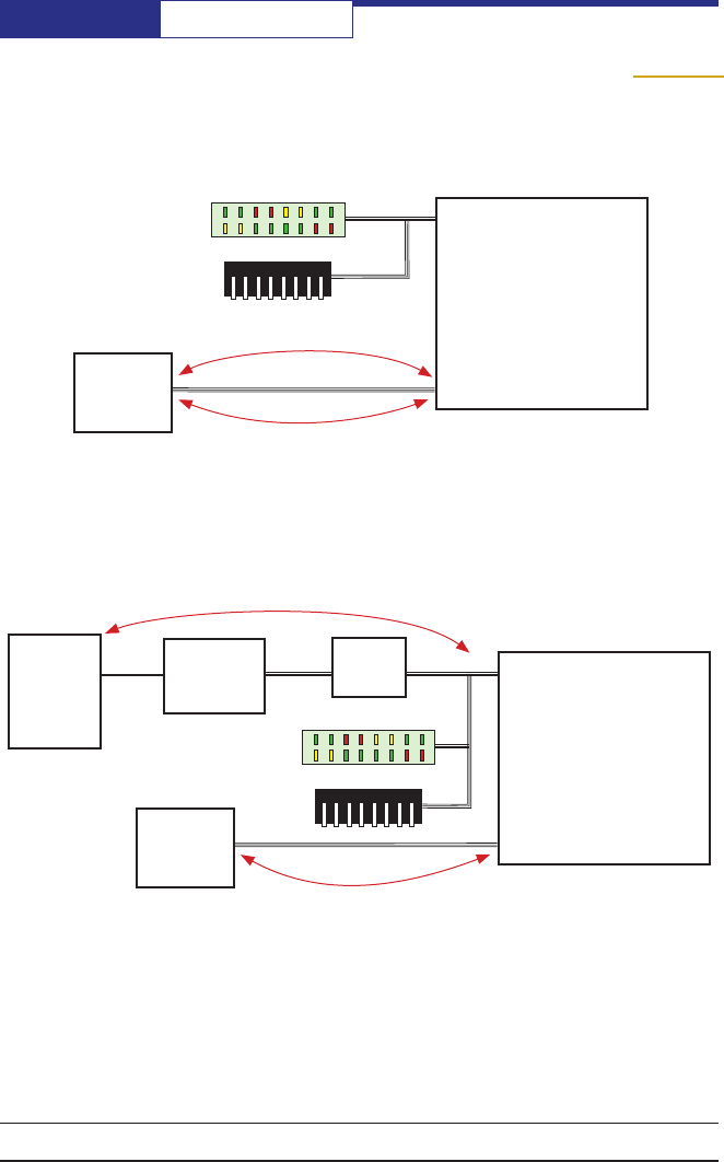
Suggested UART User Implementation:
Diagnostic LEDs
Conguration DIPs
PC
Single Port
USB to UART
Chip
UART
to SPI
Chip
USB UART 0 SPI 0
UART data at 9600 to 115,200 bps
conguration data and statistics
User’s
Embedded
µController
(Recommended
but not required)
Suggested SPI User Implementation:
Diagnostic LEDs
Conguration DIPs
AvaLAN
MOD090-HP
SPI 0
SPI data at 12 Mbps
conguration data and statistics
User’s
Embedded
µController
SPI 1
(Recommended
but not required)
Note that if you are using the MOD090-HP in UART mode, you may wish to include
a USB interface to SPI0 similar to that implemented in the Evaluation Board. This
would allow you to modify the conguration, to read back operating statistics and
to perform spectrum analysis. If those capabilities are not needed, then the cost
and space can be avoided.
Implementation Block Diagrams
AvaLAN
MOD090-HP

PAGE 29
Technical support (650) 384-0000 www.avalanwireless.com
MOD090-HP
User’s Manual
Technical specications
CHARACTERISTIC MOD090-HPMMCX
RF transmission rate 200 Kbps to 2.38 Mbps
Data Throughput 1.63 Mbps
Maximum Output power +30 dBm at 2.38 Mbps
+30 dBm at 200 Kbps
Minimum Output power +10 dBm at 2.38 Mbps
+10 dBm at 200 Kbps
Output Power Increment +1 dBm
Radio Modes OFDM, OQPSK, using proprietary TDMA
Support for IEEE 802.15.4g modes
Receiver Sensitivity -94 dBm at 2.38 Mbps
-107 dBm at 200 Kbps
Range 60 miles at 2.38 Mbps
100 miles at 200 Kbps
RF channels/bandwidth 19 non-overlapping OFDM channels at 1.2 MHz
Frequency selection Automatic or manually selectable
RF Interfaces MMCX
Data Encryption 128Bit AES CBC, OFB, CFB, CTR, ECB modes
Antenna Detection Reected power detector (VSWR) can analyze antenna
and RF cable problems
Error correction technique Forward error correction and retransmission
Adjacent band rejection SAW receiver lter attenuates cellular and pager
interference
Power consumption Transmit: 12 Watts
Receive: 0.8 Watts
Voltage 6 VDC
Temperature range -40º C to +85º C
Size 68 x 88 x 7 mm not including connectors

MOD090-HP User’s Manual
PAGE 30
Technical support (650) 384-0000 www.avalanwireless.com
FCC Certication
The MOD090-HP RF module complies with Part 15 of the FCC rules and regulations. Compliance with the labeling requirements, FCC notices, and
antenna usage guidelines is required. To operate under AvaLAN Wireless FCC Certication, RF modules/integrators must comply with the following
regulations:
1. The system integrator must ensure that the text provided with this device (see FCCRequired Label Text on page 11) is placed on the
outside of the nal product and within the nal product operation manual.
2. The AW900G2HP RF module may be used only with antennas that have been tested and approved for use with this module refer to
AW900G2HP Approved Antennas on page 31.
Labeling Requirements
In order to inherit AvaLAN’s FCC Certication, compliance requires the following be stated on the device and within its operation manual:
FCC ID: R4N-AW900G2HP This device complies with Part 15 of the FCC Rules. Operation is subject to the following two conditions: (1) this device may
not cause harmful interference and (2) this device must accept any interference received, including interference that may cause undesired operation.
Label Warning WARNING The Original Equipment Manufacturer (OEM) must ensure that FCC labeling requirements are met. This includes a clearly
visible label on the outside of the nal product enclosure that displays the contents shown in the gure below.
Figure A.1. Required FCC Label for OEM products containing the AvaLAN MOD090-HP OEM RF Module
Contains FCC ID: R4N-AW900G2HP
The enclosed device complies with Part 15 of the FCC Rules. Operation is subject to the following
two conditions: (i.) this device may not cause harmful interference and (ii.) this device must accept
any interference received, including interference that may cause undesired operation.
FCC Notices
Adherence to the following is required:
IMPORTANT: The AW900G2HP OEM RF Modules has been certied by the FCC for use with other products without any further certication (as per FCC
section 2.1091). Changes or modications not expressly approved by AvaLAN could void the user’s authority to operate the equipment.
IMPORTANT: The RF module has been certied for remote and base radio applications. If the module will be used for portable applications, the device
must undergo SAR testing.
This equipment has been tested and found to comply with the limits for a Class B digital device, pursuant to Part 15 of the FCC Rules. These limits are
designed to provide reasonable protection against harmful interference in a residential installation. This equipment generates, uses and can radiate
radio frequency energy and, if not installed and used in accordance with the instructions, may cause harmful interference to radio communications.
However, there is no guarantee that interference will not occur in a particular installation.
If this equipment does cause harmful interference to radio or television reception, which can be determined by turning the equipment off and on, the
user is encouraged to try to correct the interference by one or more of the following measures: Re-orient or relocate the receiving antenna, Increase
the separation between the equipment and receiver, Connect equipment and receiver to outlets on different circuits, or Consult the dealer or an
experienced radio/TV technician for help.
FCC Limited Modular Approval
This is an RF module approved for Limited Modular use operating as a mobile transmitting device with respect to section 2.1091 and is limited
to OEM installation for Mobile and Fixed applications only. During nal installation, end-users are prohibited from access to any programming
parameters. Professional installation adjustment is required for setting module power and antenna gain to meet EIRP compliance for high gain
antenna(s).
Final antenna installation and operating congurations of this transmitter including antenna gain and cable loss must not exceed the EIRP of the
conguration used for calculating MPE. Grantee (AvaLAN) must coordinate with OEM integrators to ensure the end-users and installers of products
operating with the module are provided with operating instructions to satisfy RF exposure requirements.
The FCC grant is valid only when the device is sold to OEM integrators. Integrators are instructed to ensure the end-user has no manual instruc-
tions to remove, adjust or install the device.
Module and Host Product Labelling Requirements
Any product for which Modular Approval (MA) or Limited Modular Approval (LMA) is being sought shall meet the above labelling requirements.
The Host Marketing Name (HMN) must be displayed (according to e-labelling requirements) or indicated at any location on the exterior of the
host product or product packaging or product literature, which shall be available with the host product or online.
The host product shall be properly labelled to identify the modules within the host product.
The Innovation, Science and Economic Development Canada certication label of a module shall be clearly visible at all times when installed in
the host product; otherwise, the host product must be labelled to display the Innovation, Science and Economic Development Canada certica-
tion number for the module, preceded by the word “Contains” or similar wording expressing the same meaning, as follows:
Contains IC: 5303A-AW900G2HP where: 5303A-AW900G2HP is the module’s certication number.
The applicant for a certied module shall provide with each certied module to the user, either a host label, such as described above, or an
explanation and instructions to the user as to the host product labelling requirements.
Antenna Warning
WARNING: This device has been tested with MMCX connectors with the antennas listed in AW900G2HP Approved Antennas on page 31. When integrated
into OEM products, xed antennas require installation preventing end-users from replacing them with non-approved antennas. Antennas not listed in
the AW900G2HP Approved Antennas on page 31 must be tested to comply with FCC Section 15.203 (unique antenna connectors) and Section 15.247
(emissions).

PAGE 31
Technical support (650) 384-0000 www.avalanwireless.com
MOD090-HP
User’s Manual
WARNING: WARNING: The FCC requires that all spread spectrum devices operating within the Unlicensed radio frequency bands must limit themselves
to a maximum radiated power of 4 Watts EIRP. Failure to observe this limit is a violation of our warranty terms, and shall void the user’s authority to
operate the equipment. This can be stated as follows:
RF power - cable loss + antenna gain <= 36 dBm EIRP
Fixed Base Station and Mobile Applications
AvaLAN Modules are pre-FCC approved for use in xed base station and mobile applications. When the antenna is mounted at least 20 cm (8”) from
nearby persons, the application is considered a mobile application.
Portable Applications and SAR Testing
When the module will be used closer than 20 cm to nearby persons, then the application is considered “portable” and requires an additional test be
performed on the nal product. This test is called the Specic Absorption Rate (SAR) testing and measures the emissions from the module and how
they affect the person.
RF Exposure
(This statement must be included as a CAUTION statement in OEM product manuals.)
WARNING: This equipment is approved only for mobile and base station transmitting devices. Antenna(s) used for this transmitter must be installed
to provide a separation distance of at least 22.72 cm from all persons and must not be co-located or operating in conjunction with any other antenna
or transmitter.
To fulll FCC Certication requirements:
1. Integrator must ensure required text [Figure 1] is clearly placed on the outside of the nal product.
2. AW900G2HP Module may be used only with Approved Antennas that have been tested with this module.
IC RSS-102 RF Exposure statement:
This system has been evaluated for RF Exposure per RSS-102 and is in compliance with the limits specied by Health Canada Safety Code 6. The system
must be installed at a minimum separation distance from the antenna to a general bystander of 33.76 cm to maintain compliance with the General
Population limits.
L’exposition aux radiofréquences de ce système a été évaluée selon la norme RSS-102 et est jugée conforme aux limites établies par le Code de
sécurité 6 de Santé Canada. Le système doit être installé à une distance minimale de 33.76 cm séparant l’antenne d’une personne présente en
conformité avec les limites permises d’exposition du grand public.
Antenna Pattern Type Gain
Omni directional Monopole ≤ 6dBi
Directional Yagi ≤ 15dBi
Directional Panel ≤ 10dBi
Type certied Antennas
IC (Industry Canada) Certication
This device complies with Industry Canada licence-exempt RSS standard(s). Operation is subject to the following two conditions: (1) this device may
not cause interference, and (2) this device must accept any interference, including interference that may cause undesired operation of the device.
Le présent appareil est conforme aux CNR d'Industrie Canada applicables aux appareils radio exempts de licence. L'exploitation est autorisée aux deux
conditions suivantes: (1) l'appareil ne doit pas produire de brouillage, et (2) l'utilisateur de l'appareil doit accepter tout brouillage radioélectrique subi,
même si le brouillage est susceptible d'en compromettre le fonctionnement.
Contains Model AW900G2HP Radio, IC: 5303A-AW900G2HP
Integrator is responsible for its product to comply with IC ICES-003 & FCC Part 15, Sub. B - Unintentional Radiators. ICES-003 is the same as FCC Part
15 Sub. B and Industry Canada accepts FCC test report or CISPR 22 test report for compliance with ICES-003.
Transmitters with Detachable Antennas
This radio transmitter (IC: 1846A-XLRP) has been approved by Industry Canada to operate with the antenna types listed in AW900G2HP Approved Anten-
nas abov with the maximum permissible gain and required antenna impedance for each antenna type indicated. Antenna types not included in this list,
having a gain greater than the maximum gain indicated for that type, are strictly prohibited for use with this device.
Le présent émetteur radio (IC: 1846A-XLRP) a été approuvé par Industrie Canada pour fonctionner avec les types d'antenne énumérés ci?dessous et
ayant un gain admissible maximal et l'impédance requise pour chaque type d'antenne. Les types d'antenne non inclus dans cette liste, ou dont le gain
est supérieur au gain maximal indiqué, sont strictement interdits pour l'exploitation de l'émetteur.
Detachable Antenna
Under Industry Canada regulations, this radio transmitter may operate using only an antenna of a type and maximum (or lesser) gain approved for
the transmitter by Industry Canada. To reduce potential radio interference to other users, the antenna type and its gain should be so chosen that the
equivalent isotropically radiated power (e.i.r.p.) is not more than that necessary for successful communication.
Conformément à la réglementation d'Industrie Canada, le présent émetteur radio peutfonctionner avec une antenne d'un type et d'un gain maximal
(ou inférieur) approuvépour l'émetteur par Industrie Canada. Dans le but de réduire les risques de brouillageradioélectrique à l'intention des autres
utilisateurs, il faut choisir le type d'antenne etson gain de sorte que la puissance isotrope rayonnée équivalente (p.i.r.e.) ne dépassepas l'intensité
nécessaire àl'établissement d'une communication satisfaisante.