Avalan Wireless Systems orporated AW900M Ethernet Bridge Transmitter Module User Manual Avalon Wireless
Avalan Wireless Systems Incorporated Ethernet Bridge Transmitter Module Avalon Wireless
User manual
AW900m
User’s Manual
Thank you for your purchase of the AW900m Module.
If you have any questions when configuring your AvaLAN module, please send us an email:
support@avalanwireless.com
Quick Setup for systems using the AW900m Module:
1. Attach an RPSMA 900MHz antenna to each module.
2. Plug in the AW900m module.
3. Connect an Ethernet cable from each AW900m to a network device.
4. Send Ethernet traffic. For troubleshooting see page 2.
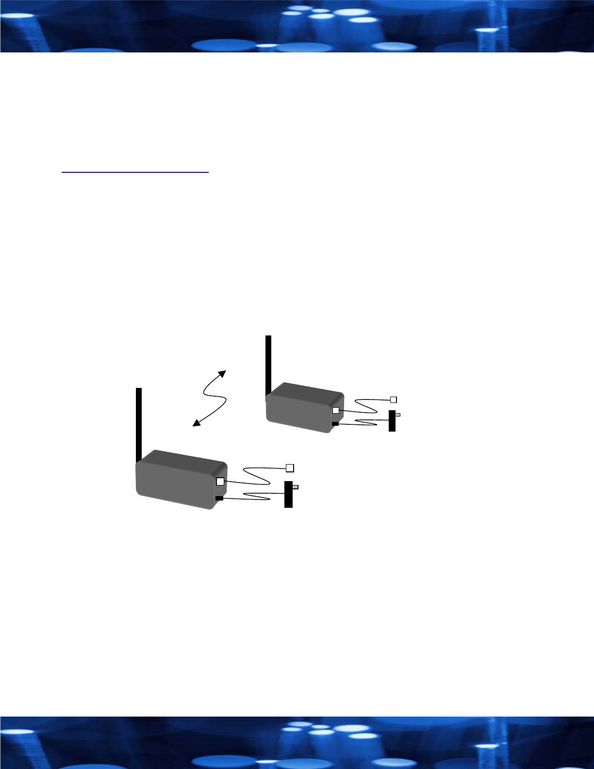
Each AW900m radio automatically selects the best radio channel, encrypts the Ethernet
traffic and transports the data wirelessly to its mate.
AW900m
Ethernet
RJ45
Power
9VDC
A
W900
m
Ethernet
RJ45
Power
9
VDC
900 MHz
Radio
Ethernet
Bridge
Any Ethernet device can be connected to the AW900m. The AW900m functions in place of
an Ethernet cable and provides a transparent wireless point to point Ethernet cable
replacement. Cross-over cables are not necessary as the AW900m automatically senses the
device (client or switch.

LED display:
The AW900m has a 16 LED display to display the status of the device.
LED Name Function Color
1 Power Unit has power and has successfully booted. Red
2 RF Link The radio has successfully linked with it partner. Green
3 RF TX Radio transmission is occurring. Green
4 RF RX Radio reception is occurring. Green
5 Eth Link The Ethernet Port has a valid Ethernet connection Green
6 Activity The AW900m is processing data Green
7 1 (channel)
8 2 (channel)
9 4 (channel)
10 8 (channel)
By adding the numbers that are lit the user can
determine the current radio channel.
1 903 MHz 7 915 MHz
2 905 MHz 8 917 MHz
3 907 MHz 9 919 MHz
4 909 MHz 10 921 MHz
5 911 MHz 11 923 MHz
6 913 MHz 12 925 MHz
Green
11 Link Quality Excellent link quality –
No retransmissions Green
12 Link Quality Very good link quality –
Few retransmissions Green
13 Link Quality Good link quality –
Occasional retransmissions Amber
14 Link Quality Fair link quality –
Some retransmissions Amber
15 Link Quality Poor link quality –
Many retransmissions Red
16 Link Quality No link quality
No link available Red
Troubleshooting:
See the online installation tutorial and FAQ at www.avalanwireless.com
No Power LED:
Check the power connections.
No Radio Link LED:
The radio is looking for its matched partner. If both units are powered up and the Power LEDs
are active they may be too far away to create the radio connection. Try other locations that
may have a less obstructed path or try to reorient the antennas.
Yagi type antennas get their best range when they are oriented to point directly at each
other with the antenna elements oriented in the same plane (eg. vertically or horizontally)
Radio LINK LED on but Link Quality Indicator is low:
The units may be too far away to create a good radio connection. Try other locations that
may have a less obstructed path or try to reorient the antennas.
No Ethernet LINK LED:
Check your network connections.
Installing Multiple systems in close proximity:
See the online installation tutorial and FAQ at www.avalanwireless.com
Still not working?
Temporarily use an Ethernet cable to see if the network is working over a wired connection.
If an Ethernet cable does not work then the problem is with the network.
Support Email: support@avalanwireless.com Support helpline: (650) 384-0000
Advanced Settings:
Automatic frequency selection mode (DIP switches – all OFF for automatic mode)
The AW900m is designed to automatically select and continuously optimize the performance
of its radio channel. The radio channel is monitored to ensure it is providing low error rates
necessary for successful radio transmission. In the event that the error rate rises, the
AW900m will autonomously change to a new channel. There are 12 non-overlapping
channels.
Manual frequency selection mode
To restrict the operation of the AW900m to a subset of the 902-928 band, the user may
activate a manual selection mode that allows the radio to automatically choose the best
channel within a grouped subset of the 12 available channels. This is enabled by the 8
position DIP switch on the master unit. These settings allow the AW900m to operate on the
optimal channel in one of three subsets, LOW 4, MID 4 or HIGH 4. The DIP switch setting
are:
Channels DIP Settin
g
Fre
q
uenc
y
LOW 4 - 1,2,3 or 4 2 On / 3 Of
f
903-909 MHz
MID 4 - 5,6,7 or 8 2 Off / 3 On 911-917 MHz
HIGH 4 - 9,10,11 or 12 2 On / 3 On 919-925 MHz
Or - the user may wish to select a specific channel. This can be done by setting DIP
switches 5-8 as shown in the table below. [Turn DIP 2 Off / 3 Off]
Channel DIP Settin
g
Fre
q
uenc
y
1 5 On / 6 Off / 7 Off / 8 O
f
f 903 MHz
2 5 Off / 6 On / 7 Off / 8 Off 905 MHz
3 5 On / 6 On / 7 Off / 8 Off 907 MHz
4 5 Off / 6 Off / 7 On / 8 Of
f
909 MHz
5 5 On / 6 Off / 7 On / 8 Off 911 MHz
6 5 Off / 6 On / 7 On / 8 Off 913 MHz
7 5 On / 6 On / 7 On / 8 Off 915 MHz
8 5 Off / 6 Off / 7 Off / 8 On 917 MHz
9 5 On / 6 Off / 7 Off / 8 On 919 MHz
10 5 Off / 6 On / 7 Off / 8 On 921 MHz
11 5 On / 6 On / 7 Off / 8 On 923 MHz
12 5 Off / 6 Off / 7 On / 8 On 925 MHz
Site survey mode (DIP switch 4 - default is OFF for normal operation)
In this mode the AW900m can perform a site survey. With this mode activated the radios
send and receive at 100% capacity by transceiving self-generated simulated data. The
installer can monitor the Link Quality display to assess channel quality while optimizing
antennae orientation. The installer can manually select each channel to evaluate
performance and identify the best channels for operation. By identifying channels with poor
performance it is possible to identify possible interferers and use “manual frequency
selection mode” to avoid portions of the band or select a fixed operating frequency.
Important note: Ethernet traffic does not get transported while the radios are in this mode.

Technical Specifications: (typical)
Characteristic Specification - description
RF transmission rate: 1.5 Mb/s
Throughput: 935 Kb/s
Output power: +21dBm – (4 Watts EIRP with 15dBi antennae)
Receive sensitivity: -97dBm at 10e-4 BER (-112dBm with 15dBi antennae)
Latency: < 1ms – assuming a dedicated wireless link to client device.
Jitter: ±0.5ms – depending upon packet size, interference and SNR.
Current consumption: Transmitting 350mA
Power: 4.5-16VDC applied at P5 power plug connector
3.0-3.2VDC applied directly at the output of the regulator
Radio channels: 12 Non-overlapping
Automatic frequency select: Yes – radio channel automatically selected and adaptively optimized
Manual frequency mode: Yes
Status LEDs: Power, RF Link, Ethernet Link, Traffic, RF RX, RF TX, 4/Channel an
d
6/Link Quality
Error correction technique: Sub-block error detection and retransmission with ACK
Adjacent-band rejection: SAW receiver filter attenuates cellular and pager interference.
Temperature range: -40°C to 70°C typical – dependant upon thermal dissipation of design
Power over Ethernet 802.3af: Use with 5VDC or 12VDC splitter with P5 connector. (Linksys WAPPOE)
Product limited warranty:
This product is warranted to the original purchaser for normal use for a period of 180 days from the date of purchase. If a
defect covered under this warranty occurs Avalan will repair or replace the defective part, at its option, at no cost. This
warranty does not cover defects resulting from misuse or modification of the product.
Compliance Statement ( Part 15.19 )
This device complies with Part 15 of the FCC Rules.
Operation is subject to the following two conditions:
1. This device may not cause harmful interference, and
2. This device must accept any interference received, including interference that may cause undesired operation.
Warning ( Part 15.21 )
Changes or modifications not expressly approved by the party responsible for compliance could void the user’s authority to operate the
equipment.
RF Exposure ( OET Bulletin 65 )
To comply with FCC RF exposure requirements for mobile transmitting devices, this transmitter should only be used or installed at locations
where there is at least 20cm separation distance between the antenna and all persons.
Information to the User - Part 15.105 (b)
Note: This equipment has been tested and found to comply with the limits for a Class B digital device, pursuant to part 15 of the FCC Rules.
These limits are designed to provide reasonable protection against harmful interference in a residential installation. This equipment generates,
uses and can radiate radio frequency energy and, if not installed and used in accordance with the instructions, may cause harmful interference
to radio communications. However, there is no guarantee that interference will not occur in a particular installation. If this equipment does
cause harmful interference to radio or television reception, which can be determined by turning the equipment off and on, the user is
encouraged to try to correct the interference by one or more of the following measures:
--Reorient or relocate the receiving antenna.
--Increase the separation between the equipment and receiver.
--Connect the equipment into an outlet on a circuit different from that to which the receiver is connected.
--Consult the dealer or an experienced radio/TV technician for help.

Appendix A: Agency Certifications
FCC Certification
The AW900m OEM RF Module complies with Part 15 of the FCC rules and regulations. Compliance with labeling
requirements, FCC notices and antenna regulations is required.
Labeling Requirements
In order to inherit AvaLAN’s FCC Certification, compliance requires the following be stated on the device:
Contains FCC ID: R4N-AW900M
The enclosed device complies with Part 15 of the FCC Rules. Operation is subject to the following
two conditions:
(1) this device may not cause harmful interference and
(2) this device must accept any interference received, including interference that may cause
undesired operation.
Figure 1. Required FCC Label for OEM products containing the AvaLAN AW900m OEM RF Module
The Original Equipment Manufacturer (OEM) must ensure that FCC labeling requirements are met. This includes a clearly
visible label on the outside of the final product enclosure that displays the contents shown in the Figure 1.
User’s manual Requirements
In order to inherit AvaLAN’s FCC Certification, compliance requires the following be stated in the user’s manual:
Compliance Statement ( Part 15.19 )
This device complies with Part 15 of the FCC Rules.
Operation is subject to the following two conditions:
1. This device may not cause harmful interference, and
2. This device must accept any interference received, including interference that may cause
undesired operation.
Warning ( Part 15.21 )
Changes or modifications not expressly approved by the party responsible for compliance could void
the user’s authority to operate the equipment.
RF Exposure ( OET Bulletin 65 )
To comply with FCC RF exposure requirements for mobile transmitting devices, this transmitter
should only be used or installed at locations where there is at least 20cm separation distance
between the antenna and all persons.
Information to the User - Part 15.105 (b)
This equipment has been tested and found to comply with the limits for a Class B digital device,
pursuant to part 15 of the FCC Rules. These limits are designed to provide reasonable protection
against harmful interference in a residential installation. This equipment generates, uses and can
radiate radio frequency energy and, if not installed and used in accordance with the instructions, may
cause harmful interference to radio communications. However, there is no guarantee that interference
will not occur in a particular installation. If this equipment does cause harmful interference to radio or
television reception, which can be determined by turning the equipment off and on, the user is
encouraged to try to correct the interference by one or more of the following measures:
--Reorient or relocate the receiving antenna.
--Increase the separation between the equipment and receiver.
--Connect the equipment into an outlet on a circuit different from that to which the receiver is
connected.
--Consult the dealer or an experienced radio/TV technician for help.
FCC Notices
Adherence to the following is required:
IMPORTANT: The AW900m OEM RF Modules have been certified by the FCC for use with other products without any
further certification (as per FCC section 2.1091). Changes or modifications not expressly approved by AvaLAN could void
the user’s authority to operate the equipment.
IMPORTANT: OEMs must test their final product to comply with unintentional radiators (FCC section 15.107 and 15.109)
before declaring compliance of their final product to Part 15 of the FCC Rules.
IMPORTANT: The AW900m OEM RF Modules have been certified for fixed base station and mobile applications. If
modules will be used for portable applications, the device must undergo SAR testing.

FCC-Approved Antennas (900 MHz)
Fixed Base Station and Mobile Applications
AvaLAN Modules are pre-FCC approved for use in fixed base station and mobile applications. When the antenna is
mounted at least 20 cm (8”) from nearby persons, the application is considered a mobile application.
Portable Applications and SAR Testing
When the antenna is mounted closer than 20 cm to nearby persons, then the application is considered “portable” and
requires an additional test be performed on the final product. This test is called the Specific Absorption Rate (SAR) testing
and measures the emissions from the module and how they affect the person.
RF Exposure
(This statement must be included as a CAUTION statement in OEM product manuals.)
WARNING: This equipment is approved only for mobile and base station transmitting devices. Antenna(s) used for this
transmitter must be installed to provide a separation distance of at least 20 cm from all persons and must not be co-
located or operating in conjunction with any other antenna or transmitter.
To fulfill FCC Certification requirements:
1. Integrator must ensure required text [Figure 1] is clearly placed on the outside of the final product.
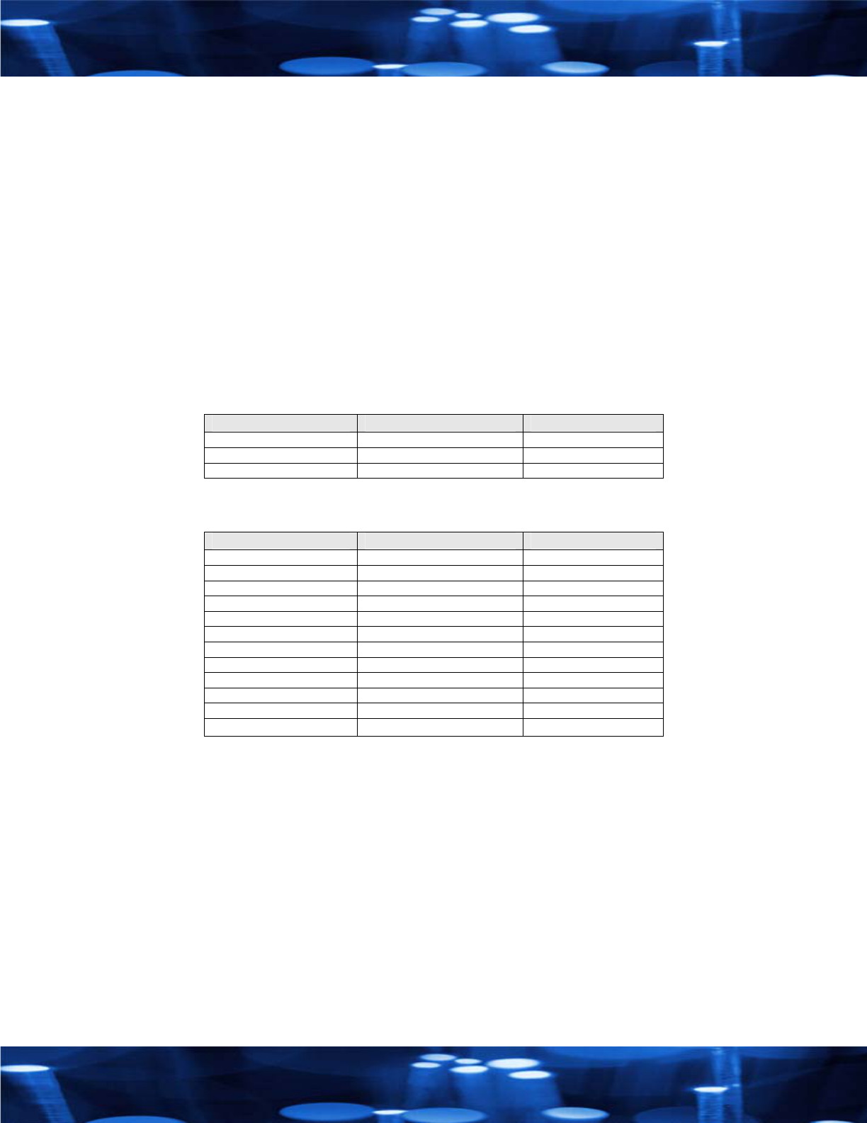
2. AW900m Module may be used only with Approved Antennas that have been tested with this module.
Pattern Type Manufacturer Part Number Gain
Omni directional Monopole Nearson S467TR-915S 2.5dBi
Omni directional Monopole Carant MG602S 8dBi
Directional Yagi Carant ACY15L 15dBi
Table 1. Certified Antennae
Antenna Warning WARNING: This device has been tested with Reverse Polarity SMA connectors with the antennas
listed in Table 1 Appendix A. When integrated into OEM products, fixed antennas require installation preventing end-users
from replacing them with non-approved antennas. Antennas not listed in the tables must be tested to comply with FCC
Section 15.203 (unique antenna connectors) and Section 15.247 (emissions).
IC (Industry Canada) Certification
Labeling requirements for Industry Canada are similar to those of the FCC. A clearly visible label on the outside of the
final product enclosure must display the following text:
Contains Model AW900 Radio, IC: 5303A-AW900M
Integrator is responsible for its product to comply with IC ICES-003 & FCC Part 15, Sub. B - Unintentional Radiators.
ICES-003 is the same as FCC Part 15 Sub. B and Industry Canada accepts FCC test report or CISPR 22 test report for
compliance with ICES-003.
AvaLAN Wireless Systems Inc.
1020 Corporation Way, Suite #207
Palo Alto, CA 94303
T(866) 533.6216
www.avalanwireless.com