Avalan Wireless Systems orporated AW900MR AW900mTR User Manual FCC Part 15
Avalan Wireless Systems Incorporated AW900mTR FCC Part 15
UserManual.wiki
>
Avalan Wireless Systems orporated
>
AW900MR User Manual
>
Manual
Contents
1.
User Manual
2.
Manual
Manual
Navigation menu
Upload a User Manual
Namespaces
Wiki Guide
HTML
PDF
Info
Views
User Manual
Discussion / Help
Navigation
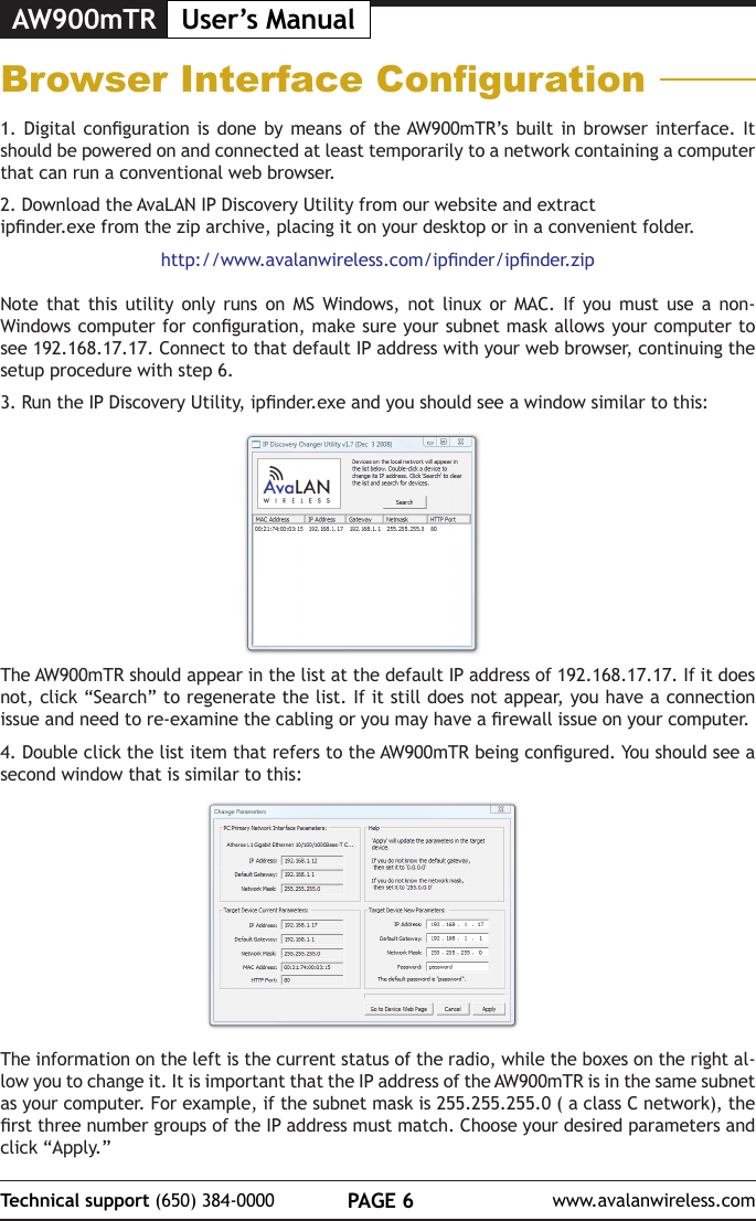
![PAGE 7Technical support (650) 384-0000 www.avalanwireless.comAW900mTRUser’s Manual7. The admin page has sections similar to the login page showing radio statistics and device information plus it adds several new sections. The Device Settings section allows setting the network information and choosing an RF frequency channel. The default is to allow the radio to choose its own frequency based on minimizing interference. If you set a xed channel, make sure the AP and all SUs use the same one. References to DIPs on this and the next web page refer to the DIP switches on the module that are used in the “easy key” method of con-guration and may be ignored when using the browser method.If you scroll down in the Admin browser page, you will come to three more sections:• A graphical spectrum analyzer display that may help you to select radio channels that avoid interference• A section to be used if an update to the AW900mTR’s rmware is required• An Advanced Links section with a dire warning about advanced users only.5. Make note of the chosen IP address and password, then click “Go to Device Web Page.” This will cause your default web browser to launch with the device IP address in the browser address bar. Or you may launch the browser on your own and enter the web page address manually: http://[the IP address you just set]. 6. The browser page that loads rst shows the current device information and QoS statistics and provides a login at the upper right. Log in using the password you just specied (or “pass-word” if you kept the default). If the login succeeds, you will see an admin page similar to this:](https://usermanual.wiki/Avalan-Wireless-Systems-orporated/AW900MR.Manual/User-Guide-2192097-Page-8.png)
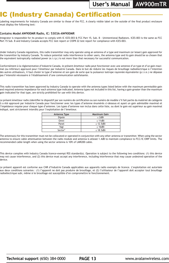
![AW900mTR User’s ManualPAGE 12Technical support (650) 384-0000 www.avalanwireless.comFCC CerticationThe AW900MTR OEM RF Module complies with Part 15 of the FCC rules and regulations. Compliance with labeling requirements, FCC notices and antenna regulations is required.Labeling RequirementsIn order to inherit AvaLAN’s FCC Certication, compliance requires the following be stated on the device and within its operation manual:FCC ID: R4N-AW900MR This device complies with Part 15 of the FCC Rules. Operation is subject to the following two conditions: (1) this device may not cause harmful interference and (2) this device must accept any interference received, including interference that may cause undesired operation.Label Warning WARNING The Original Equipment Manufacturer (OEM) must ensure that FCC labeling requirements are met. This includes a clearly visible label on the outside of the nal product enclosure that displays the contents shown in the gure below.Figure A.1. Required FCC Label for OEM products containing the AvaLAN AW900MR OEM RF ModuleContains FCC ID: R4N-AW900MRThe enclosed device complies with Part 15 of the FCC Rules. Operation is subject to the following two conditions: (1) this device may not cause harmful interference and (2) this device must accept any interference received, including interference that may cause undesired operation.FCC NoticesAdherence to the following is required:IMPORTANT: The AW900MR OEM RF Modules have been certied by the FCC for use with other products without any further certication (as per FCC section 2.1091). Changes or modications not expressly approved by AvaLAN could void the user’s authority to operate the equipment.IMPORTANT: OEMs must test their nal product to comply with unintentional radiators (FCC section 15.107 and 15.109) before declaring compli-ance of their nal product to Part 15 of the FCC Rules.IMPORTANT: The AW900MR OEM RF Modules have been certied for xed base station and mobile applications. If modules will be used for portable applications, the device must undergo SAR testing.Note: This equipment has been tested and found to comply with the limits for a Class B digital device, pursuant to Part 15 of the FCC Rules. These limits are designed to provide reasonable protection against harmful interference in a residential installation. This equipment generates, uses and can radiate radio frequency energy and, if not installed and used in accordance with the instructions, may cause harmful interference to radio communications. However, there is no guarantee that interference will not occur in a particular installation. If this equipment does cause harmful interference to radio or television reception, which can be determined by turning the equipment o and on, the user is encouraged to try to correct the interference by one or more of the following measures:• Reorient or relocate the receiving antenna.• Increase the separation between the equipment and receiving module.• Connect the equipment into an outlet on a circuit dierent from that to which the receiving module is connected.• Consult the dealer or an experienced radio/TV technician for help.FCC-Approved Antennas (900 MHz)Fixed Base Station and Mobile ApplicationsAvaLAN Modules are pre-FCC approved for use in xed base station and mobile applications. When the antenna is mounted at least 23 cm (9.06”) from nearby persons, the application is considered a mobile application.Portable Applications and SAR TestingWhen the antenna is mounted closer than 23 cm to nearby persons, then the application is considered “portable” and requires an additional test be performed on the nal product. This test is called the Specic Absorption Rate (SAR) testing and measures the emissions from the module and how they aect the person.RF Exposure(This statement must be included as a CAUTION statement in OEM product manuals.) WARNING: This equipment is approved only for mobile and base station transmitting devices. Antenna(s) used for this transmitter must be installed to provide a separation distance of at least 23 cm from all persons and must not be co-located or operating in conjunction with any other antenna or transmitter.Antenna WarningWARNING: This device has been tested with Reverse Polarity SMA connectors with the antennas listed in Table 1 below. When integrated into OEM products, xed antennas require installation preventing end-users from replacing them with non-approved antennas. Antennas not listed in the table below must be tested to comply with FCC Section 15.203 (unique antenna connectors) and Section 15.247 (emissions). To fulll FCC Certication requirements:1. Integrator must ensure required text [Figure 1] is clearly placed on the outside of the nal product.2. AW900MR Module may be used only with Approved Antennas that have been tested with this module. Antenna Type Maximum GainDipole ≤ 2dBiOmni ≤ 11dBiPanel ≤ 12.5dBiYagi ≤ 16dBiSector* ≤ 18.5dBiThis Ethernet Module is approved for use only with specic antenna, cable, and output power congurations that have been tested and approved for use. Modications to the module, the antenna system, or to the power output that have not been explicitly specied by the manufacturer are not permitted and may render the radio non-compliant with applicable regulatory authorities. The radio equipment described in this manual emits radio frequency energy. Professional installation is required. The antenna(s) for this transmitter must not be collocated or operated in conjunction with any other antenna ortransmitter. When using the sector antenna to ensure cable attentuation between the radio module and antenna is atleast 1.4dB to maintain compliance to FCC/IC EIRP limits. The recommended cable length when using the sector antenna is 10ft of LMR200 cable.](https://usermanual.wiki/Avalan-Wireless-Systems-orporated/AW900MR.Manual/User-Guide-2192097-Page-13.png)