Avante Technology SR3002 Smart-Trakker User Manual
Avante International Technology, Inc. Smart-Trakker Users Manual
Users Manual

SMART-TRAKKER™
Avante International Technology, Inc.
RFID Long Range Reader
Model SR3002
Version 1.1.0
August 23, 2005
© Avante International Technology, Inc.

User Manual Version 1.1.0 August 23, 2005 Page 2
©Avante International Technology, Inc.
Table of Contents
1. INTRODUCTION 4
2. SYSTEM HARDWARE 5
2.1 Overview 5
2.2 Smart-Tags® 5
2.3 Host 5
2.4 I/O Ports 5
2.5 Antenna 6
2.6 Power Supply 6
3. DESCRIPTION 7
3.1 Block Diagram 7
3.1.1 Power Supply 7
3.1.3 Clock Generator 7
3.1.4 Modulator, Transmitter Amplifier 7
3.1.5 Modulation Index, RF Power Regulation 7
3.1.6 Receiver, Filter, Demodulator and ADC 7
3.1.7 Optocouplers 7
3.1.7 Microcontroller 8
3.1.8 RS232 Interface 8
4. SPECIFICATIONS 9
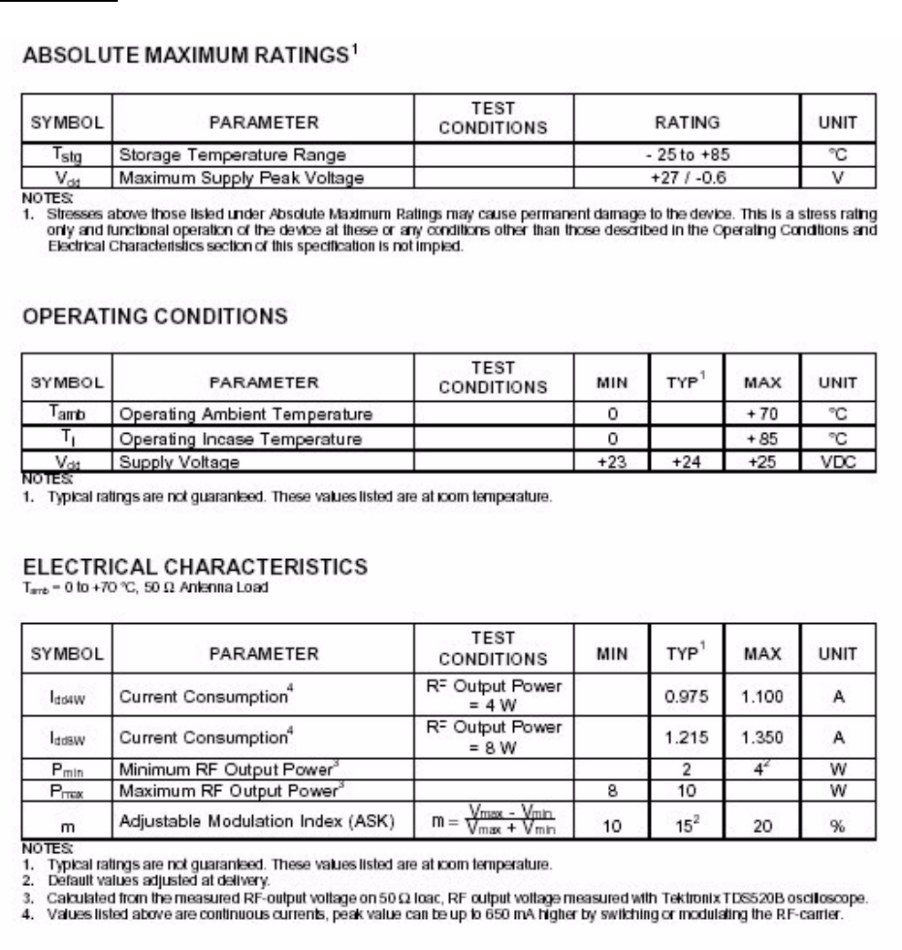
4.1 Electrical 9
4.1.1 Power Supply 9
4.1.2 Reader 10
4.2 Mechanical 11
4.2.1 Dimensions 11
4.2.2 Connectors 13
User Manual Version 1.1.0 August 23, 2005 Page 3
©Avante International Technology, Inc.
5. TROUBLESHOOTING 14
6. OPERATING CONSIDERATIONS 15
6.1 Supply Voltage 15
6.2 Antenna Opens or Shorts 15

User Manual Version 1.1.0 August 23, 2005 Page 4
©Avante International Technology, Inc.
1. INTRODUCTION
The Avante SMART-TRAKKER™ Model SR3002 RFID Long Range Reader was designed to
communicate with Avante SmartTag® RFID tags based on the ICODE IC. Read/write functionality
and methods to use the anticollision capability of ICODE are included.
The primary focus is on the long-range capability, which makes the reader suitable for gate antennas
and tunnel applications.
Should there be any questions about this manual, please visit the user section of
www.avantetech.com
or call the technical support center of
Avante International Technology, Inc.
1-800-735-5040.
Basic features of the SR-3002 Long Range Reader
• 24VDC power supply input
• 13.56 MHz carrier frequency
• RS323 serial interface, 115.2 or 57.6 KBaud data rate
• Regulated RF output power, software adjustable from 2 to 10 W @ 50 ohm
• Software adjustable modulation index (10%-20%)
• RS232 upgradable firmware
• Anticollision capability
• Standard and Fast Mode support
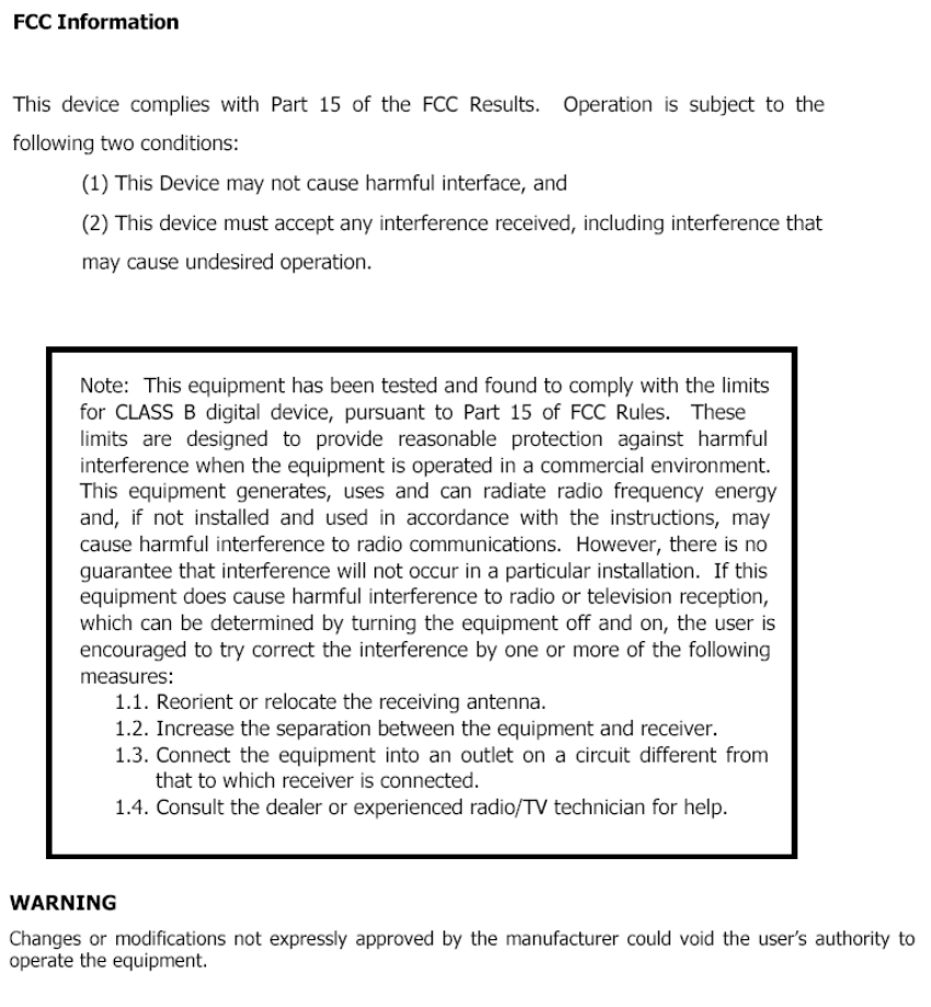
• BAPT and FCC approval
• CE compliant
User Manual Version 1.1.0 August 23, 2005 Page 5
©Avante International Technology, Inc.
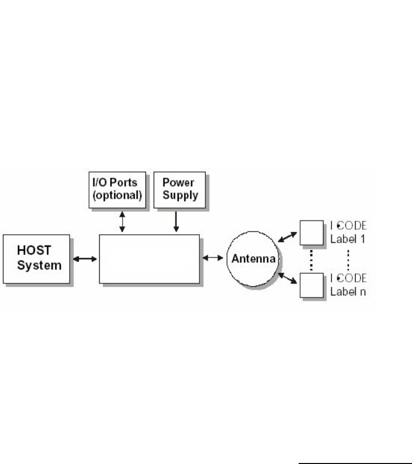
2. SYSTEM HARDWARE
2.1 OVERVIEW
The SMART-TRAKKER™ in a complete RFID system:
2.2 SMART-TAGS®
The SMART-TRAKKER™ can communicate with the ICODE IC in any Avante I-code Smart-Tag
2.3 HOST
Any PC or Laptop computer running Windows 95/98/2000/XP Operating System with the Smart-
Trakker™ Software installed and having an RS232 serial port will serve as the host.
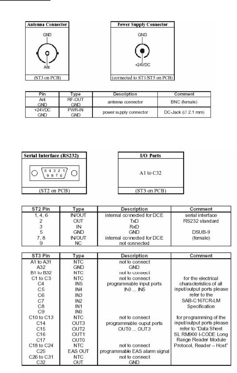
2.4 I/O PORTS
The Smart-Trakker microcontroller board has 6 input ports, 4 output ports and one EAS signal
output port all software addressable. The ports are not ESD protected, since they are not fed through
the metal housing. The data transmission connection between the Smart-Trakker™ and the Host
computer is through an RS232 serial port and cable. See the section on Reader to Host Protocol for
the communication protocol
SR3002
User Manual Version 1.1.0 August 23, 2005 Page 6
©Avante International Technology, Inc.
2.5 ANTENNA
Any Avante Smart-Trakker™ 50-ohm antenna designed for the reader can be used. A 50-ohm
coaxial cable terminating in a 50-ohm BNC connector transmits data from the antenna to the reader
2.6 POWER SUPPLY
A linear regulated power supply of 24 VDC at a maximum of 2.0A is included.

User Manual Version 1.1.0 August 23, 2005 Page 7
©Avante International Technology, Inc.
3. DESCRIPTION
3.1 BLOCK DIAGRAM
See Attachment.
3.1.1 Power Supply
Generates 24 VDC power from 120 VAC line voltage.
3.1.2 Voltage Regulation
Generates all necessary voltages for the Smart-Trakker from the 24 VDC power supply voltage.
3.1.3 Clock Generator
Generates the 13.56 MHz clock for the transmitter amplifier. A divided clock signal synchronizes
the microcontroller.
3.1.4 Modulator, Transmitter Amplifier
Modulates the carrier with a digital signal from the microcontroller for data transmission. The
Transmitter Amplifier amplifies the modulated carrier.
3.1.5 Modulation Index, RF Power Regulation
Keeps the Antenna Output Voltage to a software adjustable value. The Modulation Index is
software adjusted after any change in the RF-output power and at large temperature variations.
3.1.6 Receiver, Filter, Demodulator and ADC
The SmartTag IC sends an AM signal. This signal is converted for digital processing by the 12-bit
ADC after filtering, demodulation, and amplification.
3.1.7 Optocouplers
All internal signals are galvanically decoupled by optocouplers.

User Manual Version 1.1.0 August 23, 2005 Page 8
©Avante International Technology, Inc.
3.1.7 Microcontroller
Processes the communication protocol between the SmartTag IC and the Smart-Trakker reader. The
serial interface signals are converted so that the tag IC can process them and signals from the tag are
converted to serial interface compatible signals.
3.1.8 RS232 Interface
Communication to the host is via a serial interface with a jumper selectable baud rate of 57.6 or
115.2 kbaud.
User Manual Version 1.1.0 August 23, 2005 Page 9
©Avante International Technology, Inc.
4. SPECIFICATIONS
4.1 ELECTRICAL
4.1.1 Power Supply
The power supply supplies voltage with the following basic specifications. Although the circuit
performs some filtering of the power supplied, the input power must meet some minimum ripple
standards.
Output Voltage +24 VDC Nominal
Current 2 A Maximum
Ripple freq. 50Hz to 10 MHz 100 mV max. Amp.
10 MHz to 20 MHz 50 mV max. Amp.
20 MHz + 100 mV max. Amp.
User Manual Version 1.1.0 August 23, 2005 Page 10
©Avante International Technology, Inc.
4.1.2 Reader
User Manual Version 1.1.0 August 23, 2005 Page 11
©Avante International Technology, Inc.
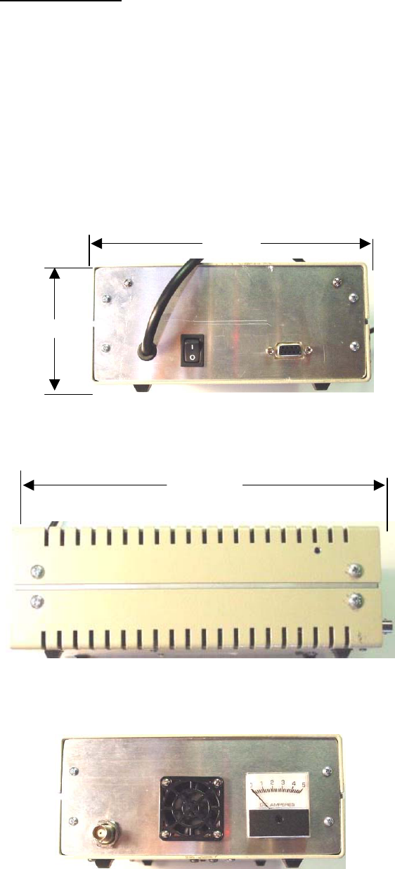
4.2 MECHANICAL
4.2.1 Dimensions
4.2.1. 1 Housing
18mm
9mm
28mm
Back View:
- Power Cord
- On/Off Switch (SW)
- RS232 Connector
Side View:
- Ventilation Slots
Front View:
- Power Meter
- Cooling Fan
- Antenna Connector
User Manual Version 1.1.0 August 23, 2005 Page 12
©Avante International Technology, Inc.
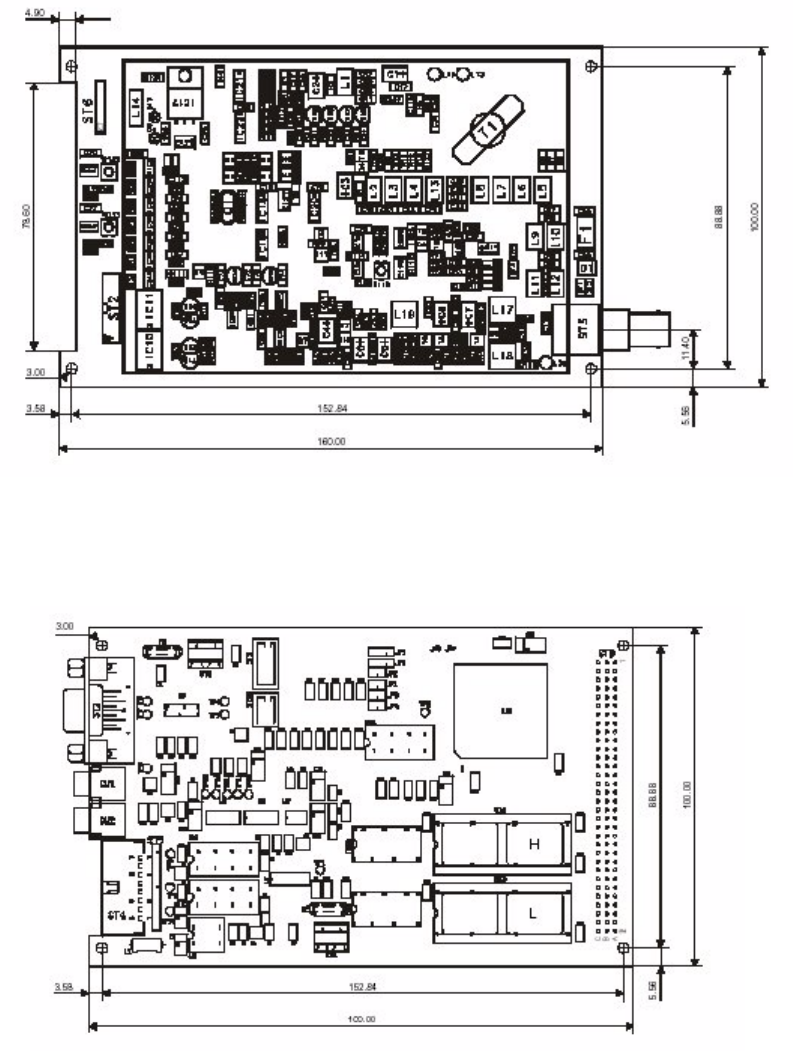
4.2.1.2 PCBs
4.2.1.2.1 RF Board
4.2.1.2.2 Microcontroller Board
User Manual Version 1.1.0 August 23, 2005 Page 13
©Avante International Technology, Inc.
4.2.2 Connectors
4.2.2.1 RF Board
4.2.2.2 Microcontroller Board
User Manual Version 1.1.0 August 23, 2005 Page 14
©Avante International Technology, Inc.
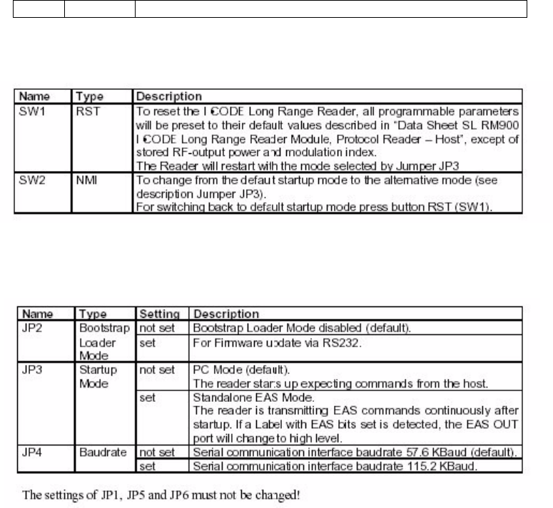
4.2.2.2.1 Switch
SW ON/OFF Connects 120VAC to Power Supply, providing power to the unit.
4.2.2.2.2 Pushbuttons
4.2.2.2.3 Microcontroller Board Jumper Settings
5. TROUBLESHOOTING
For any problems (reduced communication distances, errors or failures), check the following list:
• Power at the outlet source.
• Power supply cable not properly plugged in to the power supply or loose.
• Serial interface cable not plugged in or loose.
• Serial interface cable, power supply cord or antenna cable are too close to the antenna.
• Interference to the antenna from an external source.
• Antenna mounted on or too close to a metal environment.
User Manual Version 1.1.0 August 23, 2005 Page 15
©Avante International Technology, Inc.
6. OPERATING CONSIDERATIONS
6.1 SUPPLY VOLTAGE
The Smart-Trakker Reader is protected against supply peaks and incorrect polarity for short periods
of time. Longer periods of out-of-spec supply power will result in permanent damage to the reader.
6.2 ANTENNA OPENS OR SHORTS
The Smart-Trakker can withstand short periods of open circuit or shorting at the antenna. Permanent
damage will result from a longer uncorrected fault.
G
G
G
G
G
G
G
G
G
G
G