Avaya Canada BTR2808M LMDS BTS Transceiver User Manual
Avaya Canada Corporation LMDS BTS Transceiver
Reference guide
NTP#: 411-1333-922
Draft 01.03 November 2000
BTR 28-08 GHz MMIC
Quick Reference Guide
Product Overview
The BTR 28-08 GHz MMIC (NTVG14BH) outdoor transceiver is a state-of-the-
art broadband microwave transceiver designed to operate at various frequency
bands downstream. It is a combined broadband transmitter and receiver deployed
in Nortel Networks Reunion point-to-multipoint system. It is compatible with
Reunion’s Release 1.2, 1.3 and 1.4 equipment.
Figure 1: BTR 28M Block Diagram
Rx IF Output
Tx IF Input
Lightning
Radio Module
Protector
Lightning
Protector
Rx RF Input
Tx RF Output
Test Port
Rx IF Output
Test Port
Lightning
Protector
Telemetry Signals
BTR 28M Transceiver
Tx IF/DC Input

411-1333-922 Draft 01.03 November 2000
2
BTR 28-08 MMIC Specification
Table 1: BTR 28-08M Technical Specifications
TX IF Input RF Output
Frequency Range 2 8 - 08 M 500-650 MHz 27.50 - 27.65 GHz
Output Level (P1 dB) 26.25 dBm, -40° to +55° C
Output Level (IP3) > +34.5 dBm
Input Impedance 50 Ohms
Input/Output Connector N-Type Female WR-28 (non-standard hole pattern)
Input/Output VSWR 2.1:1, maximum 2.6:1, max (or 7 dB)
Gain (not including antenna) @ 25° C 30 ±1 dB, minimum
Gain vs. Temperature ±2.0 dB, (-40° to +55° C)
Gain Flatness ±2.0 dB over bandwidth
LO leakage <-43 dBm (outband)
Frequency Stability <±4 ppm, Over all Conditions
Antenna BTR
Frequency 27.5 - 31.3 GHz
Port-to-Port Isolation 55 dB (V/V); 55 dB (H/H)
Bore-sight Gain (Azimuth) 15.75±1.25 dBi, 90° Horn
18.9±1.25 dBi, 45°
23.8±1.3 dBi, 15°
Wave-guide Interface WR-28 (non-standard hole pattern)
Mounted on transceiver housing WR-28 flange
Size (Length x Height x Width) 10" x 9" x 2" (90°)
Polarity single polarity H/H and V/V
Sectorized Angle Available 15°, 45°, and 90°

BTR 28-08 GHz MMIC Quick Reference Guide
3
RX RF Input IF Output
Frequency Range 28-08M 27.85 - 28.00 GHz 150-300 MHz
Input/Output Connector WR-28 (non-stan-
dard hole pattern)
Type N jack (F)
Input P1 dB -13 dBm min
Output Impedance 50 Ohms
Input/Output VSWR 2.3:1, max (or 8 dB) 2.1:1 (or 9 dB), maximum
Gain (not including antenna) 29 dB
Gain Flatness ±2.0 dB over bandwidth
Gain Stability <+2.0 dB over temperature
Frequency Stability <±4 ppm, Over all Conditions
Noise Figure 7.5 dB, -40° to +55° C
Power Requirements BTR
Input Voltage -48 VDC nominal
Input Inrush Current 4.5A max
Input Power 66 Watts, maximum
Environmental BTR
Humidity 100% condensing
Altitude 10,000 feet
Operating Wind Resistance 50m/second on all surfaces
Operating Temperature -40° to +55°C
Storage Temperature Range -45° to +70°C (packaged)
Solar Loading ETS 300 019 class 4.1 1120W/m2, 50°C max.
Mechanical BTR
Size (Length x Height x Width) 19.1" x 10.3" x 5.8" (47.75 x 26 x 14.5 cm)
Weight without brackets 40 lbs. (17.8 KG)

Information is subject to change without notice.
Nortel reserves the right to make changes in
design or components as progress in engineering
and manufacturing may warrant.
© 2000 Northern Telecom Ltd.
Converted Frequency Formula
Use the following formula to calculate the converted frequency:
TX: ƒRF OUT (GHz) = 28.15 - ƒIF IN (GHz)
RX: ƒIF OUT (GHz) = 28.15 - ƒRF IN (GHz)
Note: Electrostatic deposition powder coat, scratch free.
Note: Vent holes are covered with a GoretexTM patch.
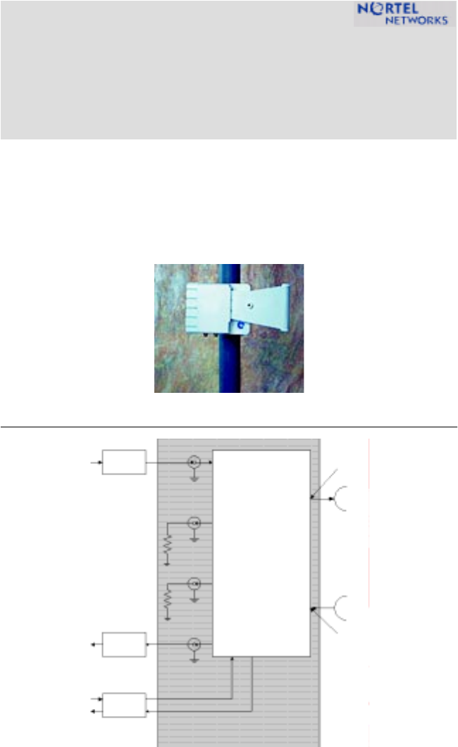
Note: The transceiver mounts to a vertical pole of 2.5” to 4.5” outside diame-
ter. It has a range of motion of 90° over and -60° under horizon. The bases of
the antenna mount can rotate ±180°.
Technical Assistance Contact Information
In case additional technical assistance is required, or the transceiver unit is
damaged upon receipt, contact Nortel Networks.
Nortel Networks Broadband Wireless Access (BWA) provides 24-hour customer
service and technical support to ensure your service operation is trouble-free.
If you have questions or need technical support, contact Nortel Networks
Broadband Wireless Access at the following telephone numbers:
• In the USA and Canada, call 972-BWA-ETAS/972-292-3827