Avaya Canada BTS18000IND GSM 18000 INDOOR BTS User Manual 411 9001 160 15104
Avaya Canada Corporation GSM 18000 INDOOR BTS 411 9001 160 15104
Exhibit 8 User manual

Wireless Service Provider Solutions
BTS18000 Reference Manual
PE/DCL/DD/0160 15.104/EN Standard June 2005
411--9001--160
Copyright ©2002--2005 Nortel Networks

< 142 > : BTS18000 Reference Manual
Wireless Service Provider Solutions
BTS18000 Reference Manual
Document number: PE/DCL/DD/0160
411--9001--160
Document status: Standard
Document issue: 15.104/EN
Product release: GSM/BSS V15.1
Date: June 2005
Copyright ©2002--2005 Nortel Networks, All Rights Reserved
Originated in France
NORTEL NETWORKS CONFIDENTIAL:
The information contained in this document is the property of Nortel Networks. Except as specifically authorized in
writing by Nortel Networks, the holder of this document shall keep the information contained herein confidential and
shall protect same in whole or in part from disclosure and dissemination to third parties and use for evaluation,
operation and maintenance purposes only.
You may not reproduce, represent, or download through any means, the information contained herein in any way or in
any form without prior written consent of Nortel Networks.
The following are trademarks of Nortel Networks: *NORTEL NETWORKS, the NORTEL NETWORKS corporate logo,
the NORTEL Globemark, UNIFIED NETWORKS, S2000, S4000, S8000. GSM is a trademark of France Telecom.
All other brand and product names are trademarks or registered trademarks of their respective holders.
Copyright ©2002--2005 Nortel Networks

Publication HistoryNortel Networks Confidential iii
BTS18000 Reference Manual
Copyright ©2002--2005 Nortel Networks
PUBLICATION HISTORY
Product release : GSM/BSS V15.1
June 2005
Issue 15.104/EN Standard
Updated the “North American regulatory requirements compliance” section.
May 2005
Issue 15.103/EN Standard
Removed the information about GSM 850.
April 2005
Issue 15.102/EN Standard
Added the following feature:
Feature 28784 “IFM1 card” (modified Section 4.2 “Interface Module (IFM)”).
April 2005
Issue 15.101/EN Preliminary
Synchronized with V15.0.1 Standard.
Removed information on BSC6000 due to EOL.
Updated for review comments.
Added the following features:
Feature 29295 “BTS18000 S444_222 dual band in single cabinet”
Feature 29068 “BTS18000 E--GSM Support”
February 2005
Issue 15.100/EN Draft
Updated document for the feature 27978 “BTS18000 support on BSC12000HC”.

Publication History Nortel Networks Confidential
iv
PE/DCL/DD/0160
411--9001--160 Standard 15.104/EN June 2005 Copyright ©2002--2005 Nortel Networks
System release: GSM/BSS V15.0.1
April 2005
Issue 15.36/EN Standard
Updated the document for CR Q01105139 (inserted Section 4.21.5 “User alarm pin
connections for GSM use”).
Modified the “BTS interconnection compliance” part of the “North American
regulatory requirements compliance” section.
April 2005
Issue 15.35/EN Standard
Updated the document with review comments.
Updated the document for feature 29066 “BTS18000 H4 Hybrid Coupler” (inserted
Section 4.9 “H4 module”).
January 2005
Issue 15.34/EN Preliminary
Updated document for requested changes relating to:
BTS18000 naming (BTS18010 for indoor version, BTS18020 for outdoor
version),
BTS18000 consumption (detailed information for full GSM BTS18020, and for
BTS18020 combo and MCPA variants -- see Section 4.19.4),
back up time of internal batteries (detailed information for full GSM BTS18020,
and for BTS18020 combo and MCPA variants -- see Section 4.19.4).
November 2004
Issue 15.33/EN Preliminary
Incorporated review comments.
October 2004
Issue 15.02/EN Preliminary
Restructured chapter 3, chapter 5 and chapter 6.
Added new type of information in modules description.

Publication HistoryNortel Networks Confidential v
BTS18000 Reference Manual
Copyright ©2002--2005 Nortel Networks
July 2004
Issue 15.01/EN Draft
Creation for feature 25808 -- BTS18000 introduction ready.

Publication History Nortel Networks Confidential
vi
PE/DCL/DD/0160
411--9001--160 Standard 15.104/EN June 2005 Copyright ©2002--2005 Nortel Networks
PAGE INTENTIONALLY LEFT BLANK

Table of contents
Nortel Networks Confidential vii
BTS18000 Reference Manual
Copyright ©2002--2005 Nortel Networks
About this document 0--1...............................................
Applicability 0--1......................................................................
Audience 0--1........................................................................
Prerequisites 0--1....................................................................
Related Documents 0--2...............................................................
How this document is organized 0--2....................................................
Vocabulary conventions 0--2...........................................................
Regulatory information 0--3............................................................
1 BTS18000 offer 1--1............................................
1.1 BTS18000 versions 1--1.....................................................
1.2 BTS18000 possible uses 1--1................................................
1.3 BTS18000 frequency bands supported for GSM 1--2............................
2 BTS18000 functionality 2--1.....................................
2.1 GSM--UMTS dual technology proposal 2--1.....................................
2.2 GSM features 2--1..........................................................
2.3 GSM functions 2--3.........................................................
3 BTS18000 cabinets description 3--1.............................
3.1 BTS18020 cabinet layout 3--2................................................
3.2 BTS18010 cabinet layout 3--4................................................
3.3 Power supply 3--6...........................................................
3.3.1 BTS18020 cabinet 3--6.............................................
3.3.2 BTS18010 cabinet 3--6.............................................
3.4 Cooling system 3--6.........................................................
3.5 Physical characteristics and environmental requirements 3--7.....................
3.5.1 BTS18020 cabinet 3--7.............................................
3.5.2 BTS18010 cabinet 3--8.............................................
4 BTS18000 modules description 4--1.............................
4.1 Interface BackPlane (IBP) and Digital BackPlane (DBP) 4--2......................
4.1.1 Main functions 4--2................................................
4.1.2 Physical and electrical characteristics 4--3............................
4.1.3 Interfaces between modules 4--3....................................
4.1.4 IBP connectors 4--4...............................................

Table of contents Nortel Networks Confidential
viii
PE/DCL/DD/0160
411--9001--160 Standard 15.104/EN June 2005 Copyright ©2002--2005 Nortel Networks
4.1.5 DBP connectors 4--6..............................................
4.1.6 Digital signals 4--7.................................................
4.1.7 Power signals 4--7.................................................
4.2 Interface Module (IFM) 4--8..................................................
4.2.1 Main functions 4--8................................................
4.2.2 Types of IFM board 4--9............................................
4.2.3 Front panel 4--9...................................................
4.2.4 Physical and electrical characteristics 4--11............................
4.2.5 Interface description 4--12...........................................
4.2.6 LEDs behavior 4--13................................................
4.3 Interface Control Module (ICM) 4--14...........................................
4.3.1 Main functions 4--14................................................
4.3.2 Front panel 4--15...................................................
4.3.3 Physical and electrical characteristics 4--17............................
4.3.4 Interface description 4--17...........................................
4.3.5 ICM Corporate LEDs behavior 4--19..................................
4.3.6 ICM specific LEDs behavior 4--20....................................
4.3.7 LEDs behavior at active ICM starting up 4--21..........................
4.3.8 LEDs behavior at passive ICM starting up 4--22........................
4.3.9 Configuration of the ICM switches for commissioning 4--23...............
4.4 Alarms and Bridge Module (ABM) 4--27.........................................
4.4.1 Main functions 4--27................................................
4.4.2 Front panel 4--28...................................................
4.4.3 Physical and electrical characteristics 4--30............................
4.4.4 Interface description 4--30...........................................
4.4.5 ABM corporate LEDs behavior 4--32..................................
4.4.6 ABM specific LEDs behavior 4--32....................................
4.4.7 LEDs behavior at ABM starting up 4--33...............................
4.5 Radio Module (RM) 4--34.....................................................
4.5.1 Main functions 4--34................................................
4.5.2 Front panel 4--34...................................................
4.5.3 Physical and electrical characteristics 4--36............................
4.5.4 Interface description 4--37...........................................
4.5.5 RM corporate LEDs behavior 4--37...................................
4.5.6 RM specific LEDs behavior 4--38.....................................
4.5.7 LEDs behavior at RM starting up 4--38................................

Table of contents
Nortel Networks Confidential ix
BTS18000 Reference Manual
Copyright ©2002--2005 Nortel Networks
4.6 High Power Radio Module (HPRM) 4--39........................................
4.6.1 Main functions 4--39................................................
4.6.2 Front panel 4--39...................................................
4.6.3 Physical and electrical characteristics 4--41............................
4.6.4 Interface description 4--41...........................................
4.6.5 HPRM LEDs behavior 4--41.........................................
4.7 Dual Duplexer Module (DDM) 4--42............................................
4.7.1 Main functions 4--42................................................
4.7.2 Front panel 4--43...................................................
4.7.3 Physical and electrical characteristics 4--45............................
4.7.4 Interface description 4--45...........................................
4.7.5 DDM specific LEDs behavior 4--46....................................
4.7.6 Configuration of the DDM switches for commissioning 4--46..............
4.8 Transmit Filter (TXF) 4--48....................................................
4.8.1 Main functions 4--48................................................
4.8.2 Front panel 4--48...................................................
4.8.3 Physical and electrical characteristics 4--49............................
4.8.4 Interface description 4--50...........................................
4.8.5 TXF specific LEDs behavior 4--50....................................
4.8.6 Configuration of the TXF switches for commissioning 4--50..............
.............................................................
................................................
...................................................
............................
...........................................
...............................
.......................................
................................................
...................................................
............................
...........................................
..................................
................................................
...........................................
............................
...........................................

List of figures
Nortel Networks Confidential xiii
BTS18000 Reference Manual
Copyright ©2002--2005 Nortel Networks
Figure 3--1 BTS18020 equipped cabinet with door opened (front view) 3--3...............
Figure 3--2 BTS18010 equipped cabinet with door opened (front view) 3--5...............
Figure 4--1 IBP and DBP interconnection architecture 4--2.............................
Figure 4--2 IBP connectors location 4--4.............................................
Figure 4--3 DBP connectors location 4--6............................................
Figure 4--4 IFM front panel 4--10.....................................................
Figure 4--5 ICM front panel 4--16....................................................
Figure 4--6 Corporate LEDs 4--19....................................................
Figure 4--7 ICM Corporate LEDs behavior 4--19.......................................
Figure 4--8 ICM SW10 switch 4--23..................................................
Figure 4--9 ICM SW11 switch 4--24..................................................
Figure 4--10 ICM Abis switch 4--25....................................................
Figure 4--11 ABM front panel 4--29....................................................
Figure 4--12 RM front panel 4--35.....................................................
Figure 4--13 HPRM front panel 4--40..................................................
Figure 4--14 DDM front panel 4--43...................................................
Figure 4--15 DDM H2 front panel 4--44................................................
Figure 4--16 TXF front panel 4--48....................................................
Figure 4--17 TXF H2 front panel 4--49.................................................
Figure 4--18 H4 module front panel 4--52..............................................
Figure 4--19 RICO module front panel 4--54............................................
Figure 4--20 RICO connectors location 4--56...........................................
Figure 4--21 RICO interconnection architecture 4--59....................................
Figure 4--22 SICS rack front view 4--62................................................
Figure 4--23 ECU damper (front view) 4--66............................................
Figure 4--24 Control PCB box (front view) 4--67.........................................
Figure 4--25 BTS18010 cabinet DC breakers (front view) 4--71...........................
Figure 4--26 UCPS interconnection architecture 4--72...................................
Figure 4--27 UCPS global front view 4--73..............................................
Figure 4--28 UCPS Rectifiers (1000W, 1400W) front panels and Filler 4--75................
Figure 4--29 UCPS DDU front panel 4--78..............................................
Figure 4--30 CDMA/GSM CCU front panel 4--82........................................
Figure 4--31 UMTS/GSM CCU front panel 4--83........................................
Figure 4--32 ADU interconnection architecture 4--88.....................................
Figure 4--33 ADU front panel 4--89....................................................
Figure 4--34 Internal batteries distribution system architecture 4--91.......................

List of figures Nortel Networks Confidential
xiv
PE/DCL/DD/0160
411--9001--160 Standard 15.104/EN June 2005 Copyright ©2002--2005 Nortel Networks
Figure 4--35 Internal batteries (front view) 4--92.........................................
Figure 4--36 User rack front panel 4--97...............................................
Figure 4--37 User ICO front panel 4--99................................................
Figure 4--38 PRIPRO2 module view (front and inside) 4--102..............................
Figure 4--39 ALPRO module view and location (BTS18010 cabinet) 4--103..................
Figure 4--40 ALPRO2 module front panel 4--104.........................................
Figure 5--1 BTS18010 block diagram for a S333 configuration 5--2......................
Figure 5--2 BTS18020 block diagram for a S333 configuration 5--3......................
Figure 5--3 BTS18000 architecture (three--cabinet configuration example) 5--4............
Figure 6--1 BTS18000 software functions 6--4........................................
Figure 6--2 RM software architecture 6--7............................................
Figure 6--3 ICM software architecture 6--9...........................................
Figure 7--1 Example: synchronization connections between master S12000
and slave BTS18000 (maximum configuration) 7--3.........................
Figure 7--2 Example: synchronization connections between master S12000
and slave BTS18000 (small configuration) 7--4.............................
Figure 8--1 Combo GSM--UMTS BTS18010 equipped cabinet with door opened
(front view) 8--4........................................................
Figure 8--2 Combo GSM--UMTS BTS18020 equipped cabinet with door opened
(front view) 8--6........................................................
............................................
...................................................
.............................................
...............................................
............................................
.............................................
............................................
............................................
.................................

List of tables
Nortel Networks Confidential xv
BTS18000 Reference Manual
Copyright ©2002--2005 Nortel Networks
Table 1--1 Frequency bands supported for GSM 1--2.................................
Table 3--1 BTS18020 dimensions and weights 3--7...................................
Table 3--2 BTS18010 dimensions and weight 3--8....................................
Table 4--1 IBP dimensions and weight 4--3..........................................
Table 4--2 DBP dimensions and weight 4--3.........................................
Table 4--3 IBP connectors type and use 4--5........................................
Table 4--4 DBP connectors type and use 4--7........................................
Table 4--5 IFM dimensions and weight 4--11..........................................
Table 4--6 IFM connectors type and use 4--12........................................
Table 4--7 ICM dimensions and weight 4--17..........................................
Table 4--8 ICM connectors type and use 4--17........................................
Table 4--9 ICM specific LEDs behavior 4--20..........................................
Table 4--10 ICM SYN LEDs behavior 4--21............................................
Table 4--11 LEDs behavior at active ICM starting up 4--22...............................
Table 4--12 LEDs behavior at passive ICM starting up 4--22.............................
Table 4--13 ICM SW10 switch configuration 4--23......................................
Table 4--14 ICM SW11 switch configuration 4--24......................................
Table 4--15 ICM Abis switch -- T1 configuration 4--26...................................
Table 4--16 ICM Abis switch -- E1 configuration 4--26...................................
Table 4--17 ABM dimensions and weight 4--30.........................................
Table 4--18 ABM connectors type and use 4--30.......................................
Table 4--19 ABM corporate LEDs behavior 4--32.......................................
Table 4--20 ABM specific LEDs behavior 4--32.........................................
Table 4--21 LEDs behavior at ABM starting up 4--33....................................
Table 4--22 RM dimensions and weight 4--36..........................................
Table 4--23 RM output power per frequency band 4--36.................................
Table 4--24 RM corporate LEDs behavior 4--37........................................
Table 4--25 RM TRX 0--1--2 LEDs behavior 4--38.......................................
Table 4--26 LEDs behavior at RM starting up 4--38.....................................
Table 4--27 HPRM dimensions and weight 4--41.......................................
Table 4--28 DDM / DDM H2 dimensions and weight 4--45...............................
Table 4--29 DDM specific LEDs behavior 4--46.........................................
Table 4--30 DDM switches configuration 4--46.........................................
Table 4--31 TXF / TXF H2 dimensions and weight 4--49.................................
Table 4--32 TXF specific LEDs behavior 4--50.........................................
Table 4--33 TXF switches configuration 4--50..........................................

List of tables Nortel Networks Confidential
xvi
PE/DCL/DD/0160
411--9001--160 Standard 15.104/EN June 2005 Copyright ©2002--2005 Nortel Networks
Table 4--34 H4 module dimensions and weight 4--53....................................
Table 4--35 RICO dimensions and weight 4--55........................................
Table 4--36 RICO connectors type and use 4--58.......................................
Table 4--37 SICS dimensions and weight 4--62.........................................
Table 4--38 SICS alarm LEDs behavior 4--63..........................................
Table 4--39 ECU components weight 4--68............................................
Table 4--40 ECU alarm LEDs behavior 4--69...........................................
Table 4--41 Rectifier dimensions and weight 4--76......................................
Table 4--42 Rectifiers corporate LEDs behavior 4--76...................................
Table 4--43 DDU dimensions and weight 4--79.........................................
Table 4--44 DDU connectors type and use 4--80.......................................
Table 4--45 CCU (CDMA/GSM or UMTS/GSM) dimensions and weight 4--84..............
Table 4--46 CDMA/GSM CCU connectors type and use 4--84............................
Table 4--47 UMTS/GSM CCU connectors type and use 4--85............................
Table 4--48 CCU (CDMA/GSM or UMTS/GSM) corporate LEDs behavior 4--86.............
Table 4--49 UMTS/GSM CCU specific LEDs behavior 4--87..............................
Table 4 -- 50 A DU dim ens ions and weight 4 -- 90.........................................
Table 4--51 Internal batteries weight 4--93.............................................
Table 4--52 Back up time of internal batteries 4--94.....................................
Table 4--53 User rack dimensions and weight 4--98.....................................
Table 4--54 User ICO dimensions and weight 4--100.....................................
Table 4--55 User ICO connectors type 4--100...........................................
Table 4--56 User alarm pin connections for GSM use 4--101..............................
Table 6--1 ICM software product names 6--3........................................
Table 6--2 RM software product names 6--3.........................................
Table 9--1 MRM dimensions and weight 9--4........................................
Table 9--2 MCPA cabinet dimensions 9--11...........................................
Table 9--3 MCPA cabinet weight 9--11...............................................

About this documentNortel Networks Confidential 0--1
BTS18000 Reference Manual
Copyright ©2002--2005 Nortel Networks
ABOUT THIS DOCUMENT
This document describes the new BTS18000 Base Transceiver Station (BTS),
which is a component of the Base Station Subsystem (BSS).
It applies to:
BTS18010 (also known as the BTS18000 Indoor)
BTS18020 (also known as the BTS18000 Outdoor)
BTS18000 -- GSM MCPA (for GSM MCPA configuration)
BTS18000 -- GSM--UMTS (for GSM--UMTS combo configurations)
Applicability
This document applies to the V15.1 BSS system release.
Audience
This document is intended for operation and maintenance personnel, and for any
user who needs information relating to the BTS18000.
Prerequisites
It is recommended that the readers also become familiar with the following
documents:
< 000 > : BSS Product Documentation Overview
< 001 > : BSS Overview
< 007 > : BSS Operating Principles
< 039 > : BSS Maintenance Principles
< 124 > : BSS Parameter Dictionary
< 125 > : Observation Counter Dictionary
< 128 > : OMC--R User Manual -- Volume 1 of 3: Object and Fault menus
< 129 > : OMC--R User Manual -- Volume 2 of 3: Configuration, Performance,
and Maintenance menus
< 130 > : OMC--R User Manual -- Volume 3 of 3: Security, Administration,
SMS--CB, and Help menus
< 161 > : BTS18000 Fault Number Description -- Volume 9 of 9
< 162 > : BTS18000 Maintenance Manual
The following engineering document: GSM/GPRS/EDGE BSS Engineering Rules
(PE/DCL/DD/0138) also contains relevant information.

About this document Nortel Networks Confidential
0--2
PE/DCL/DD/0160
411--9001--160 Standard 15.104/EN June 2005 Copyright ©2002--2005 Nortel Networks
Related Documents
The NTPs listed in the above paragraph are quoted in the document.
How this document is organized
Chapter 1 presents the BTS18000 offer.
Chapter 2 describes the BTS18000 functionality.
Chapter 3 describes the layout and content of the BTS18000 cabinets.
Chapter 4 describes the BTS18000 modules.
Chapter 5 examines the BTS18000 functional architecture.
Chapter 6 describes the BTS18000 software.
Chapter 7 presents the BTS18000 operated in a synchronized co--location mode.
Chapter 8 describes the GSM--UMTS dual mode configurations.
Chapter 9 describes the MCPA BTS18000 configurations.
Chapter 10 indicates where the dimensioning and configuration rules are described.
Vocabulary conventions
The glossary is included in the NTP < 000 >.

About this documentNortel Networks Confidential 0--3
BTS18000 Reference Manual
Copyright ©2002--2005 Nortel Networks
Regulatory information
This part which provides the regulatory information concerning the BTS is split into
the following items:
European regulatory requirement compliance,
North American regulatory requirement compliance,
Compliances for other regions/countries,
Operation conditions,
Cable specifications,
Product labeling.
European regulatory requirement compliance
As a radio product, the Nortel Networks BTS18000 falls under the requirement of
the RTTE (Radio and Telecom Terminal Equipment) European directive
1999/5/EEC. The RTTE directive covers essential requirements in the field of:
protection of the Health and Safety of the user and any other person, including the
objectives with respect to safety requirements contained in the Low Voltage
directive (73/23/EEC).
the protection requirements with respect to EMC contained in Directive
89/336/EEC.
The equipment generates, uses, and can radiate radio frequency energy. If not
installed and used in accordance with the instruction manual, the equipment may
cause harmful interference to radio communications. However, there is no
guarantee that interference will not occur in a particular installation. If this
equipment does cause harmful interference to radio or television reception,
which can be determined by turning the equipment off and on, the user is
encouraged to try to correct the interference.
The EMC requirements have been selected to ensure an adequate level of
compatibility for apparatus at residential, commercial, and light industrial
environments. The levels however, do not cover extreme cases which may occur
in any location but with a low probability of occurrence. In particular, it may not
cover those cases where a potential source of interference which is producing
individually repeated transient phenomena, or continuous phenomena, is
permanently present, for example a radar or broadcast site in the near vicinity. In
such a case it may be necessary to either limit the source of interference, or use
special protection applied, to the interfered part, or both.
Note: For operation or maintenance inside Nortel Networks systems, the
antistatic wrist shall always be used to maintain the integrity of the
product.

About this document Nortel Networks Confidential
0--4
PE/DCL/DD/0160
411--9001--160 Standard 15.104/EN June 2005 Copyright ©2002--2005 Nortel Networks
effective use of the Radio spectrum allocated to terrestrial/space radio
communication and orbital resources so as to avoid harmful interference. The
routes and standards used to demonstrate compliance with there essential
requirements are outlined in the following paragraphs.
-- BTS EMC
Compliance with the essential requirements of EMC has been demonstrated using
EN301489--1 & --23 standard.
-- BTS radio compliance
Compliance with the essential requirements of effective use of the radio spectrum
has been demonstrated using EN301908--1 & --3 standard.
-- BTS safety
Compliance with the essential requirements of Safety has been demonstrated using
EN 60950 Standard.
-- BTS health protection
Compliance with the essential requirement of health requirement has been
demonstrated using EN50385.
North American regulatory requirements compliance
The Nortel Networks BTS18000 has been qualified according to North American
market requirements for the Indoor, Outdoor, and MCPA versions.
This equipment has been tested and found to comply with the limits for a Class B
digital device, pursuant to part 15 of the FCC Rules. These limits are designed to
provide reasonable protection against harmful interference in a residential
installation. This equipment generates, uses and can radiate radio frequency energy
and, if not installed and used in accordance with the instructions, may cause harmful
interference to radio communications. However, there is no guarantee that
interference will not occur in a particular installation. If this equipment does cause
harmful interference to radio or television reception, which can be determined by
turning the equipment off and on, the user is encouraged to try to correct the
interference by one or more of the following measures:
reorient or relocate the receiving antenna.
increase the separation between the equipment and receiver.
connect the equipment into an outlet on a circuit different from that to which the
receiver is connected.
consult the dealer or an experienced radio/TV technician for help.
-- BTS safety
Nortel Networks BTS18000 complies with UL60950 and CAN/CSA C22.2 No.
60950--00 Safety Standards. The CSA mark is applied on the BTS and demonstrates
compliance with both US and Canadian Standards.

About this documentNortel Networks Confidential 0--5
BTS18000 Reference Manual
Copyright ©2002--2005 Nortel Networks
-- BTS EMC and radio compliance
Nortel Networks BTS18000 complies with 47CFR Part 15 class B and 47 CFR Part
24 for EMC and radio emission limits according to US regulatory requirements as
indicated on the regulatory label.
-- BTS interconnection compliance
The Nortel Networks BTS18000 complies with 47 CFR Part 68 of the FCC rules
and the requirements adopted by the ACTA.
On the top right of this equipment is a label that contains, among other information,
a product identifier in the following format: US : AB6XDNANBTS18000
If requested, the following information must be provided to the telephone company:
ACTA Registered Number: AB6.
Facility Interface Code (FIC): 04DU9.BN, 04DU9.DN, 04DU9.1KN, and
04DU9.1SN.
Service Order Code (SOC): 6.0F.
A FCC part 68 and ACTA compliant cable is provided with the BTS equipment,
with no connector at network interface side. The BTS equipment operates with a
1.544 Mbps digital channel. See Installation Instructions for details.
If the BTS18000 equipment causes harm to the phone network, the telephone
company will notify you in advance that temporary discontinuance of service may
be required. But if advance notice isnot practical, the telephone company will notify
the customer as soon as possible. Also, you will be advised of your right to file a
complaint with the FCC if you believe it is necessary.
The telephone company may make changes to its facilities, equipment, operations
or procedures that could affect the operation of the equipment. If this happens the
telephone company will provide advance notice so you can make the necessary
modifications to maintain uninterrupted services.
If trouble is experienced with BTS18000 equipment, for repair or warranty
information, please contact:
Toy--Brent Lorance Nortel Networks
2370D Performance Dr.
Richardson, TX 75082
Phone: 972--685--2270
Fax: 972--684--7601
If the equipment is causing harm to the telephone network, the telephone company
may request that you disconnect the equipment until the problem is resolved.
All repairs should be handled by authorized Nortel Networks Service Personnel.
-- BTS18000 data equipment
The following table shows which jacks are associated with which modes of
operation.
About this document Nortel Networks Confidential
0--6
PE/DCL/DD/0160
411--9001--160 Standard 15.104/EN June 2005 Copyright ©2002--2005 Nortel Networks
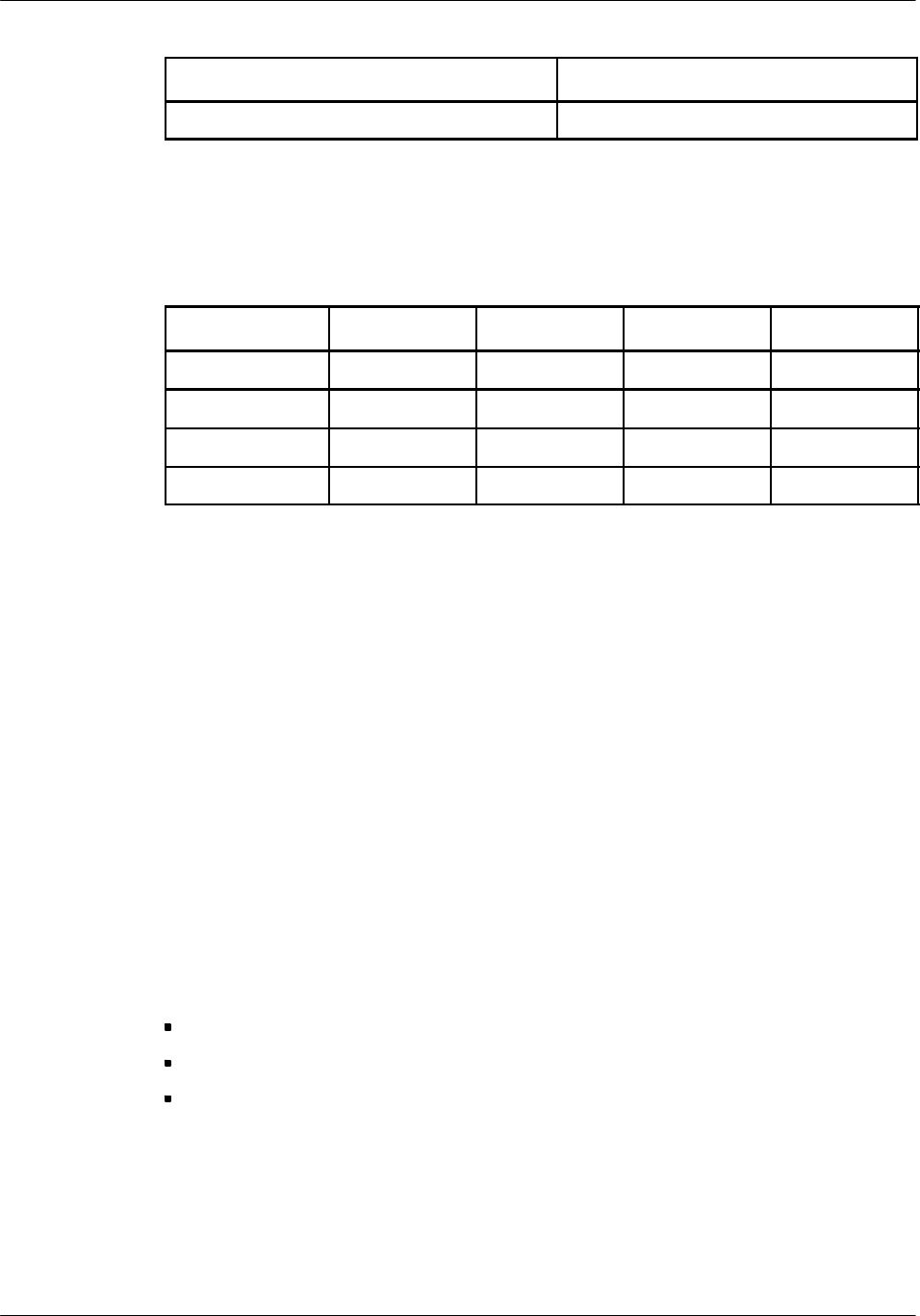
Operation mode USOC Jack
Programmable & Test RJ45S
-- BTS18000 systems
Facility Interface Codes (FIC), Services Order Codes (SOC), USOC Jack Codes,
and Ringer Equivalence Number (REN) are shown in the table below for each port
where applicable.
Port FIC SOC USOC Jack REN
ICM T1 board 04DU9.BN 6.0F N/A N/A
ICM T1 board 04DU9.DN 6.0F N/A N/A
ICM T1 board 04DU9.1KN 6.0F N/A N/A
ICM T1 board 04DU9.1SN 6.0F N/A N/A
-- BTS18000 RF health protection
Compliance with the North American requirements is demonstrated through
calculation according to FCC OET bulletin 65.
Compliances for other regions/countries
For countries outside Europe and the Americas, the requirements of European
countries usually apply.
It is not possible to list all the applicable approvals/compliances as they will be
dependent on the markets and products considered.
Note: Please contact your local Nortel Networks representative for more
information.
Operational conditions
The aforementioned standards compliance of the products are based on the
following operating conditions (called normal operation):
doors shall be closed and (or) covers shall be in place.
external cables shall be of the same type as specified by Nortel Networks.
no modification of any mechanical or electrical characteristics of the product
shall be made.
Any change or modification made to the product without written approval from
Nortel Networks releases Nortel Networks from subsequent responsibility
regarding the standards compliance.
About this documentNortel Networks Confidential 0--7
BTS18000 Reference Manual
Copyright ©2002--2005 Nortel Networks
Cable specifications
The compliance to the aforementioned standards has been verified using cables as
specified by Nortel Networks. The continuing compliance of the product relies
upon use of the correct cabling scheme as well as use of identical type cables as
specified by Nortel Networks. Refer to the installation guides for details on cable
specifications.
Product labeling
The label may be located inside or outside the product, provided that the operation
and/or maintenance personnel have the information when working on the product.
-- BTS labeling for American Countries
To indicate compliance with the CSA and UL Safety requirements, the Nortel
Networks BTS18000 bears the following mark in a conspicuous location.
On the regulatory label, compliance to 47 CFR Part 15, 24 and 68 is stated along
with:
FCC ID, FCC Registration Number.
Manufacturers name.
Equipment designation.
Nominal voltage operating range and maximum rated current.
-- BTS labeling for European Countries
To indicate compliance with the European RTTE Directive, the Nortel Networks
BTS18000 bears the following information in a conspicuous location:

About this document Nortel Networks Confidential
0--8
PE/DCL/DD/0160
411--9001--160 Standard 15.104/EN June 2005 Copyright ©2002--2005 Nortel Networks
Manufacturers name.
Equipment designation.
Nominal voltage operating range and maximum rated current.
-- Labeling for other regions / countries
Labeling for other regions and countries is performed as appropriate and required
by the local regulatory framework.

BTS18000 offerNortel Networks Confidential 1--1
BTS18000 Reference Manual
Copyright ©2002--2005 Nortel Networks
1 BTS18000 OFFER
1.1 BTS18000 versions
The BTS18000 is proposed in standard in two main versions:
BTS18000 indoor, named BTS18010,
BTS18000 outdoor, named BTS18020.
Both can provide up to 18 TRXs per cabinet.
In addition to the two standard BTS18010 and BTS18020 versions, the BTS18000
is proposed in two variants:
Combo GSM/UMTS dual mode variant, proposed in BTS18010 and BTS18020
version,
MCPA variant, with increased number of TRXs per cabinet used in conjunction
with MCPA cabinet, proposed in BTS18020 version.
1.2 BTS18000 possible uses
The BTS18000, which is meant for various operating environments:
replaces the S8000 or S12000 BTSs in Nortel Networks portfolio for greenfield
site deployments.
provides continuity to the S8000 and S12000 BTSs by its ability to be operated in
a synchronized co--location mode, to increase the capacity of existing S8000 or
S12000 sites.

BTS18000 offer Nortel Networks Confidential
1--2
PE/DCL/DD/0160
411--9001--160 Standard 15.104/EN June 2005 Copyright ©2002--2005 Nortel Networks
1.3 BTS18000 frequency bands supported for GSM
Table 1--1 shows the GSM frequency bands supported.
Name Uplink
(mobile transmit,
base receive)
Downlink
(base transmit,
mobile receive)
GSM900
E--GSM900
P--GSM900
880 -- 905 MHz
890 -- 915 MHz
925 -- 950 MHz
935 -- 960 MHz
GSM1800 1710 -- 1785 MHz 1805 -- 1880 MHz
GSM1900 1850 -- 1910 MHz 1930 -- 1990 MHz
Table 1--1 Frequency bands supported for GSM
where:
P--GSM900 = Primary or Standard GSM900 band.
E--GSM900 = Extended GSM900 band (includes part of the Standard GSM900
band)
Note: The GSM900 band (35MHz) is covered by two 25MHz RF combiner part
band variants.

BTS18000 functionalityNortel Networks Confidential 2--1
BTS18000 Reference Manual
Copyright ©2002--2005 Nortel Networks
2 BTS18000 FUNCTIONALITY
2.1 GSM--UMTS dual technology proposal
The BTS18000 is designed to integrate, within the same cabinet, both
GSM/GPRS/EDGE and UMTS technologies.
This configuration is available on all GSM frequency variants (900, 1800, and 1900
MHz) and on both 1900 and 2100 MHz frequency variants for UMTS. The
maximum one--cabinet configuration is GSM S333 + UMTS STSR--2.
2.2 GSM features
The BTS18000 offers a set of features enhancing the Quality of Service and the
spectrum efficiency of the network such as:
Full support of GPRS data services.
Full support of EDGE 8PSK modulation.
Guaranteed --110 dBm dynamic single--branch receive sensitivity (GMSK
modulation) at the BTS antenna, without any tower--mounted Low Noise
Amplifier (LNA).
Improved receiver diversity gain using a Nortel Networks specific algorithm,
providing 5 dB or more diversity gain in most situations, when spatial diversity
and de--correlated antennas are used.
High output power with a 30W or 40W standard Power Amplifier (PA), and an
optional 60W High Power Amplifier:
•
30W/30W (GSM1800, GSM1900),
•
40W/40W for standard RM (GSM900),
•
60W/45W for GSM900 HPRM (GMSK/EDGE power).
The BTS18020 cabinet can also be used as a very high density BTS in
conjunction with an optional cabinet housing Multi Carrier Power Amplifiers
(MCPA) and TX/RX antenna combiners.
The MCPA feature (available only in GSM1900) allows high radio capacities
using fewer RF feeders (8--Carriers per feeder at 43 dBm typical between the
MCPA cabinet and the antenna) and antennas:
•
without the coverage penalties of hybrid combiner solutions,
•
without the frequency hopping limitations of cavity combiner solutions.
The MCPA feature leads to a S16.16.16 configuration in two BTS cabinets and
one MCPA cabinet. The BTS18020 cabinet then contains up to 27 TRX without
power amplification. This BTS configuration is ideal for urban deployment with
severe space limitations and high capacity demands without compromising radio
coverage. One of its major benefits is the antenna number limitation (two per
sector).

BTS18000 functionality Nortel Networks Confidential
2--2
PE/DCL/DD/0160
411--9001--160 Standard 15.104/EN June 2005 Copyright ©2002--2005 Nortel Networks
Dual--band GSM configurations with single--BCCH, built in a single or in
multiple BTS18000 cabinets.
Enhanced voice quality due to an innovative algorithm of interference
cancellation significantly reducing the end--user’s perception of errors generated
in the radio transmission.
Full RF power control range (static and dynamic).
Spectrum efficiency optimization with the support of the undisputed Nortel
Networks capacity features that provide high quality voice and data services to a
dense subscriber population, in a limited spectrum and at competitive cost.
These solutions include Fractional Frequency Reuse, Automated Cell Tiering
and Adaptive Multi Rate (AMR) support.
Best--in--class radio performance thanks to high sensitivity receivers, unique
interference cancellation and improved spatial diversity algorithms along with
high output power, providing optimum coverage and link quality for both data
and voice services.
High integration of advanced technology.
This in turn contributes to a significant reduction in required floor space, size and
equipment operating costs. This concept is adapted to stringent environmental
constraints and is leading to the best economic trade--off between initial and final
capacity.
In addition, the BTS18000 supports asymmetrical radio configurations such as
S963 in one cabinet.
Compatibility with the S8000 and S12000 BTSs:
•
through existing site synchronized co--location,
•
through the possibility to re--use existing site equipment (such as an
S8000/S12000 outdoor plinth).
Industry leading transmission solution including high signaling concentration on
the Abis interface and drop--and--insert capability.
As an example, a single timeslot is only required for carrying the signaling of a
S333 BTS.
Only two PCM timeslots over the Abis interface are required for each 8--radio
timeslot TRX.
For signaling:
•
only one PCM timeslot is required, with configurations up to S333,
•
only three PCM timeslots are required, with configurations up to S999,
•
only six PCM timeslots are required, with configurations up to S18.18.18.
The BTS18000 can support eight E1/T1 PCM links, with a granularity of four
E1/T1 per IFM board.

BTS18000 functionalityNortel Networks Confidential 2--3
BTS18000 Reference Manual
Copyright ©2002--2005 Nortel Networks
The drop--and--insert capability is used to reduce the number of PCM links
needed to connect the BTSsto their BSC. This can be implemented through chain
connection or loop connection, depending on the level of reliability required.
The BTS18000 supports the drop--and--insert function exactly the same way as
the S8000 and S12000 BTSs do. Therefore, it is possible to have the S8000,
S12000 and BTS18000 BTSs on the same chain or loop.
GSM/GPRS/EDGE and UMTS dual technology capabilities for operator
evolution to 3G data services.
2.3 GSM functions
The BTS18000 provides:
the radio interface with the mobile handsets,
the associated signal processing and the transmission interface with the Base
Station Controller (BSC).
The BTS18000 ensures the following main functions:
RF functions:
•
Antenna coupling and duplexing,
•
Power amplification,
•
Reception, including RF 2--way receive diversity,
•
Gaussian Minimum Shift Keying (GMSK) modulation/demodulation,
•
8--Phase Shift Keying (8--PSK) EDGE modulation/demodulation,
•
Synthesized frequency hopping in all hybrid coupling types.
Radio channel management:
•
BTS and mobile handset power control,
•
Discontinuous Transmission and Voice Activity Detection (DTX/VAD), on
both uplink and downlink paths,
•
Radio channel filling,
•
Call setup and release,
•
Mobile timing advance processing,
•
Support of Enhanced Full--Rate (EFR), Full--Rate (FR), AMR Full--Rate and
AMR Half--Rate speech coding,
Signal processing:
•
Channel encoding and decoding,
•
Encryption (A5/2 and A5/1),

BTS18000 functionality Nortel Networks Confidential
2--4
PE/DCL/DD/0160
411--9001--160 Standard 15.104/EN June 2005 Copyright ©2002--2005 Nortel Networks
•
Equalization,
•
Cancellation of interference,
•
Processing of radio measurements, including handover algorithms,
Interface with the BSC:
•
Communication with the BSC,
•
Concentration of signaling on the Abis interface (a single PCM timeslot can
concentrate signaling for up to nine transceivers),
•
Multiplexing of four traffic channels on one PCM slot (each TRX needs two
PCM slots for traffic).
Switching:
•
Connection between the PCM links and the traffic/signaling channels,
•
Management of drop--and--insert connections,
•
Management of the TRX and PCM link redundancy.
Operation and Maintenance:
•
High level of availability through optional duplication of switching,
synchronization and control unit (working in active/stand--by mode) and
optional N+1 redundancy for rectifiers and RM,
•
Monitoring of internal and external alarms, through internal bus and alarm
loops,
•
Remote configuration management from the BSC (site, sector, Abis, TRX),
•
Remote software downloading.

BTS18000 cabinets descriptionNortel Networks Confidential 3--1
BTS18000 Reference Manual
Copyright ©2002--2005 Nortel Networks
3 BTS18000 CABINETS DESCRIPTION
This chapter presents the BTS18000 cabinet layout for both BTS18020 and
BTS18010 versions.
For the BTS18020 as well as for the BTS18010, the cabinet includes two shelves
(see Figure 5--3 of Chapter 5 for a functional view of these two shelves). Each shelf
contains:
one combiner rack,
one digital rack.

BTS18000 cabinets description Nortel Networks Confidential
3--2
PE/DCL/DD/0160
411--9001--160 Standard 15.104/EN June 2005 Copyright ©2002--2005 Nortel Networks
3.1 BTS18020 cabinet layout
The BTS18020 can be housed in one or several cabinets depending on the required
capacity:
One base cabinet can provide up to 18 TRX (in GSM--only mode) or 9 TRX (in
GSM--UMTS dual mode).
Up to two additional extension cabinets can be added. Each extension cabinet can
support up to 18 TRX.
The BTS18020 cabinet includes the following elements:
outdoor enclosure including AC Distribution Unit (ADU),
AC/DC power supply: Univity Compact Power System (UCPS),
optional internal batteries,
Environmental Control Unit (ECU),
User Rack space and its associated User ICO,
back--planes: Interface Back--Plane (IBP) and Digital Back--plane (DBP), not
visible on Figure 3--1,
one Radio InterCOnnect board (RICO),
up to two Interface Modules (IFM),
one Interface Control Module (ICM) or two ICMs (in a redundant
configuration),
up to two Alarm and Bridge Modules (ABM),
up to two optional ALarm secondary PROtection (ALPRO2) boxes,
up to six Radio Modules (RM) or High Power Radio Modules (HPRM),
up to six Dual Duplexer Modules (DDM) or DDM with optional H2 coupling
(DDM H2), with optional Voltage Standing Wave Ratio (VSWR) meter.
At the same location, optional Transmit Filters (TXF) or TXF with optional H2
coupling (TXF H2), with optional VSWR meter, can be provided.
Note: The DDM modules are physically grouped into the two combiner racks.
Each digital rack consists of the association of IFM, ICM, ABM and RM
modules.
Note: IFM and ICM modules are not required in a BTS18000 extension cabinet.
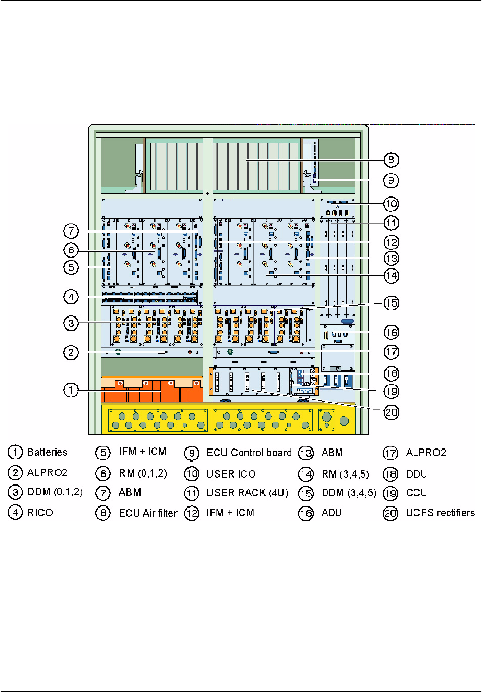
Figure 3--1 presents the BTS18020 cabinet layout and situates the modules in a fully
equipped cabinet.
BTS18000 cabinets descriptionNortel Networks Confidential 3--3
BTS18000 Reference Manual
Copyright ©2002--2005 Nortel Networks
Figure 3--1 BTS18020 equipped cabinet with door opened (front view)

BTS18000 cabinets description Nortel Networks Confidential
3--4
PE/DCL/DD/0160
411--9001--160 Standard 15.104/EN June 2005 Copyright ©2002--2005 Nortel Networks
3.2 BTS18010 cabinet layout
The BTS18010 cabinet includes the following elements:
indoor enclosure,
DC breaker panel,
BTS18000 Integrated Cooling System (SICS),
back--planes: Interface Back--Plane (IBP) and Digital Back--plane (DBP), not
visible on Figure 3--2,
one Radio InterCOnnect board (RICO),
up to two Interface Modules (IFM),
one Interface Control Module (ICM) or two ICMs (in a redundant
configuration),
up to two Alarm and Bridge Modules (ABM),
up to six Radio Modules (RM),
up to six Dual Duplexer Modules (DDM) or DDM with optional H2 coupling
(DDM H2), with optional VSWR meter.
At the same location, optional Transmit Filters (TXF) or TXF with optional H2
coupling (TXF H2), with optional VSWR meter, can be provided.
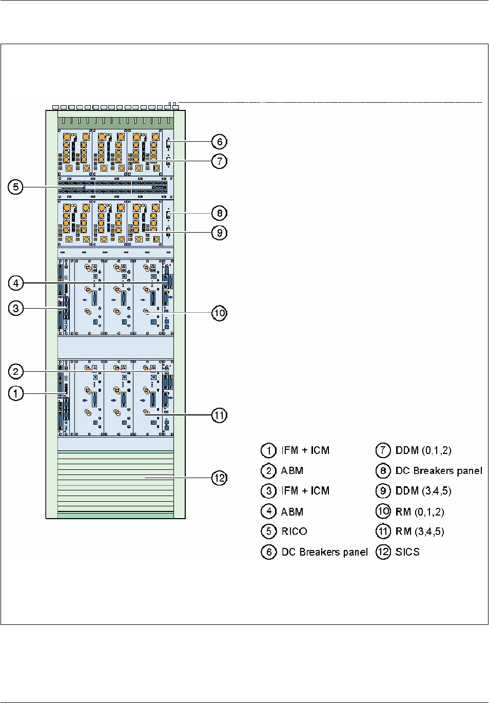
Figure 3--2 presents the BTS18010 cabinet layout and situates the modules in a fully
equipped cabinet.
BTS18000 cabinets descriptionNortel Networks Confidential 3--5
BTS18000 Reference Manual
Copyright ©2002--2005 Nortel Networks
Figure 3--2 BTS18010 equipped cabinet with door opened (front view)

BTS18000 cabinets description Nortel Networks Confidential
3--6
PE/DCL/DD/0160
411--9001--160 Standard 15.104/EN June 2005 Copyright ©2002--2005 Nortel Networks
3.3 Power supply
3.3.1 BTS18020 cabinet
The outdoor cabinet provides an AC input. The AC Distribution Unit (ADU)
performs AC protection, filtering and distribution.
The UCPS power supply system delivers --48V DC voltage from the AC input. The
UCPS also manages optional internal or external batteries.
For detailed information, refer to Chapter 4.
3.3.2 BTS18010 cabinet
There are two variants of pre--cabled cabinet, --48V and +24V, according to the DC
input.
3.4 Cooling system
There are two cooling systems, depending on the BTS18000 cabinet version:
The BTS18000 Indoor Cooling System (SICS), for BTS18010 cabinet.
See Section 4.11 for detailed information.
The Environmental Control Unit (ECU), for BTS18020 cabinet.
See Section 4.12 for detailed information.
BTS18000 cabinets descriptionNortel Networks Confidential 3--7
BTS18000 Reference Manual
Copyright ©2002--2005 Nortel Networks
3.5 Physical characteristics and environmental requirements
3.5.1 BTS18020 cabinet
As shown in Table 3--1, the weights and dimensions of the BTS18020 cabled
cabinet allows for installations using generally available installation tools and
methods. Key construction features are:
Cabled cabinet design integrating all mechanical sub--racks and mechanical
support systems required for the installation, transport and operation of the GSM
wireless equipment.
Centralized single Environmental Control Unit (ECU), supplying standardized
cooling performance regardless of BTS configuration.
AC Distribution Unit (ADU).
Standardized AC/DC distribution system, allowing BTS minimum to maximum
configuration expansion: Univity Compact Power System (UCPS).
Standardized Radio InterCOnnection module (RICO), allowing minimum to
maximum BTS configuration expansion.
Standardized digital back--plane assembly (DBP), allowing minimum to
maximum BTS configuration expansion.
BTS18020 cabinet Height
mm
Width
mm
Depth
mm
Weight
Kg
BTS18020 pre--cabled cabinet 1500 1350 735 180
BTS18020 fully equipped cabinet 1500 1350 735 450
Table 3--1 BTS18020 dimensions and weights
The BTS18020 cabinet is designed to support an external temperature range of
-- 4 0 _Cto+50_C with an absolute humidity between 1 g/m3 and 36 g/m3.
The BTS18020 enclosure is designed for an outdoor environment.
Combo GSM--UMTS and MCPA variants of BTS18020 cabinet support the same
environmental conditions.
BTS18000 cabinets description Nortel Networks Confidential
3--8
PE/DCL/DD/0160
411--9001--160 Standard 15.104/EN June 2005 Copyright ©2002--2005 Nortel Networks
3.5.2 BTS18010 cabinet
As shown in the Table 3--2, the weight and dimensions of the BTS18010 cabled
cabinet allows for installations using generally available installation tools and
methods. Key construction features are:
Cabled cabinet design integrating all mechanical sub--racks and mechanical
support systems required for the installation, transport and operation of the GSM
wireless equipment.
Centralized single low acoustic noise BTS18000 Indoor Cooling System (SICS),
supplying standardized cooling performance regardless of BTS configuration.
Standardized DC distribution system, allowing BTS minimum to maximum
configuration expansion.
Standardized Radio InterCOnnection module (RICO), allowing minimum to
maximum BTS configuration expansion.
Standardized digital back--plane assembly (DBP), allowing minimum to
maximum BTS configuration expansion.
BTS18010 cabinet Height
mm
Width
mm
Depth
mm
Weight
Kg
BTS18010 pre--cabled cabinet 1750 600 600 120
BTS18010 fully equipped cabinet 1750 600 600 300
Table 3--2 BTS18010 dimensions and weight
The BTS18010 cabinet is designed to support an external temperature range of
-- 5 _Cto+45_C with an absolute humidity between 1 g/m3 and 29 g/m3.
The BTS18010 enclosure is designed for a standard indoor environment.
Combo GSM--UMTS variant of BTS18010 cabinet supports the same
environmental conditions.

BTS18000 modules descriptionNortel Networks Confidential 4--1
BTS18000 Reference Manual
Copyright ©2002--2005 Nortel Networks
4 BTS18000 MODULES DESCRIPTION
This chapter describes the BTS18000 modules, shared between the following
subsystems:
BTS18000 Common Function Modules:
•
IBP and DBP,
•
IFM,
•
ICM,
•
ABM.
BTS18000 Radio Modules:
•
RM,
•
HPRM,
•
TX and RX RF Coupling Modules:
–DDM, DDM H2, DDM with VSWR meter, or DDM H2 with VSWR
meter,
–TXF, TXF H2, TXF with VSWR meter, or TXF H2 with VSWR meter.
•
RICO.
BTS18000 Cabinet Modules:
•
for BTS18010 cabinet, SICS.
•
for BTS18020 cabinet:
–ECU,
–UCPS,
–ADU,
–Internal batteries,
–User rack and User ICO.
BTS18000 Ancillaries Modules:
•
ALPRO,
•
ALPRO2,
•
PRIPRO,
•
PRIPRO2.
BTS18000 modules description Nortel Networks Confidential
4--2
PE/DCL/DD/0160
411--9001--160 Standard 15.104/EN June 2005 Copyright ©2002--2005 Nortel Networks
4.1 Interface BackPlane (IBP) and Digital BackPlane (DBP)
The IBP and DBP backplanes span across the whole rack and are common to
BTS18010 and BTS18020 cabinets. They are field replaceable.
All modules and some cables carrying external signals are plugged into connectors
mounted on the backplanes printed--circuit board.
4.1.1 Main functions
The IBP and the DBP provide the electrical interfaces that support DC power
distribution and communication between all digital and radio modules.
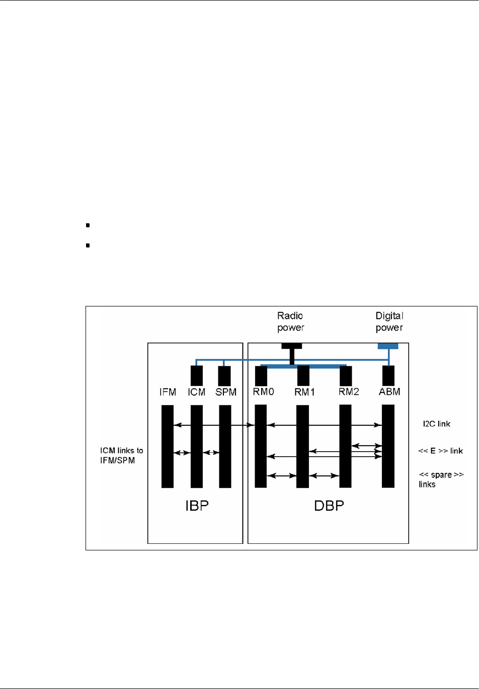
The IBP and DBP functions are split as follows:
the IBP routes low power and dense digital signals for ICM and IFM.
the DBP routes RM high power, digital boards low power and a few digital
signals for ABM and RMs.
Figure 4--1 illustrates the interconnection architecture of BTS18000 backplanes.
Figure 4--1 IBP and DBP interconnection architecture

BTS18000 modules descriptionNortel Networks Confidential 4--3
BTS18000 Reference Manual
Copyright ©2002--2005 Nortel Networks
4.1.2 Physical and electrical characteristics
Module
name
Height
(mm)
Width
(mm)
Depth of the associated shelf
(mm)
Weight
(Kg)
IBP 290 75 415 <1
Table 4--1 IBP dimensions and weight
Maximum number per cabinet: 2.
No power dissipation.
Maximum voltage: 60 V.
Warning: The IBP distributes 48V power.
Module
name
Height
(mm)
Width
(mm)
Depth of the associated shelf
(mm)
Weight
(Kg)
DBP 120 311 415 <1
Table 4--2 DBP dimensions and weight
Maximum number per cabinet: 2 (3 for MCPA BTS18020 cabinet).
No power dissipation.
Maximum voltage: 60 V.
Warning: The DBP distributes 48V power.
4.1.3 Interfaces between modules
The IBP and DBP interface with IFM, ICM, ABM and RMs using multiple
high--density connectors, for digital signal path, and power connectors. The RM
connectors are placed in order to optimize the DC power distribution distance on
the backplane. The RM power traces, on the backplane and ground plane, can
handle a current of up to 45A.
The interface between IBP and DBP is performed via a digital and power cable.
BTS18000 modules description Nortel Networks Confidential
4--4
PE/DCL/DD/0160
411--9001--160 Standard 15.104/EN June 2005 Copyright ©2002--2005 Nortel Networks
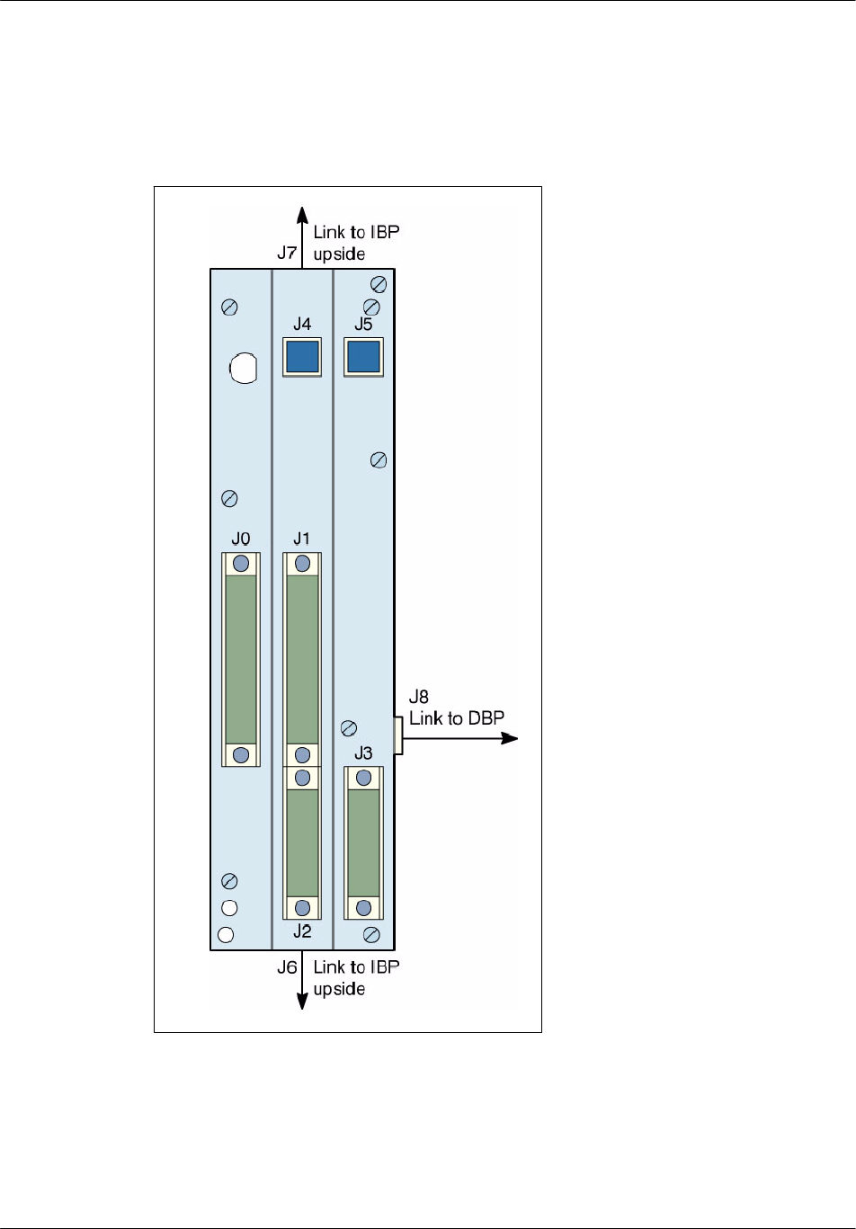
4.1.4 IBP connectors
Figure 4--2 locates all the connectors on the IBP module. They are front panel
connectors, except for J8, which is located on the right side of IBP.
Figure 4--2 IBP connectors location
Table 4--3 indicates the type and the use of the IBP connectors.

BTS18000 modules descriptionNortel Networks Confidential 4--5
BTS18000 Reference Manual
Copyright ©2002--2005 Nortel Networks
IBP connectors Use Type
J0 Connection between IBP and IFM
H
M
1
2
1
0
p
i
n
s
m
a
l
e
J1 Connection between IBP and ICM
H
M
1 210 p
i
ns ma
l
e
J2 Connection between IBP and ICM
H
M
1
1
2
0
p
i
n
s
m
a
l
e
J3 --
H
M
1 120 p
i
ns ma
l
e
J4 Connection between IBP and ICM (ICM power)
H
M
1
3
0
p
i
n
s
m
a
l
e
J5 --
H
M
130p
i
ns ma
l
e
J6
C
o
n
n
e
c
t
i
o
n
b
e
t
w
e
e
n
t
w
o
I
B
P
s
D
U
B
O
X
6
p
i
n
s
f
e
m
a
l
e
J7
C
onnect
i
on
b
etween two
I
B
P
s
D
U
B
O
X
6p
i
ns
f
ema
l
e
J8 (on IBP right side) Connection between IBP and DBP (I2C link,
detect, 48V power) DUBOX 26 pins female
Table 4--3 IBP connectors type and use
BTS18000 modules description Nortel Networks Confidential
4--6
PE/DCL/DD/0160
411--9001--160 Standard 15.104/EN June 2005 Copyright ©2002--2005 Nortel Networks
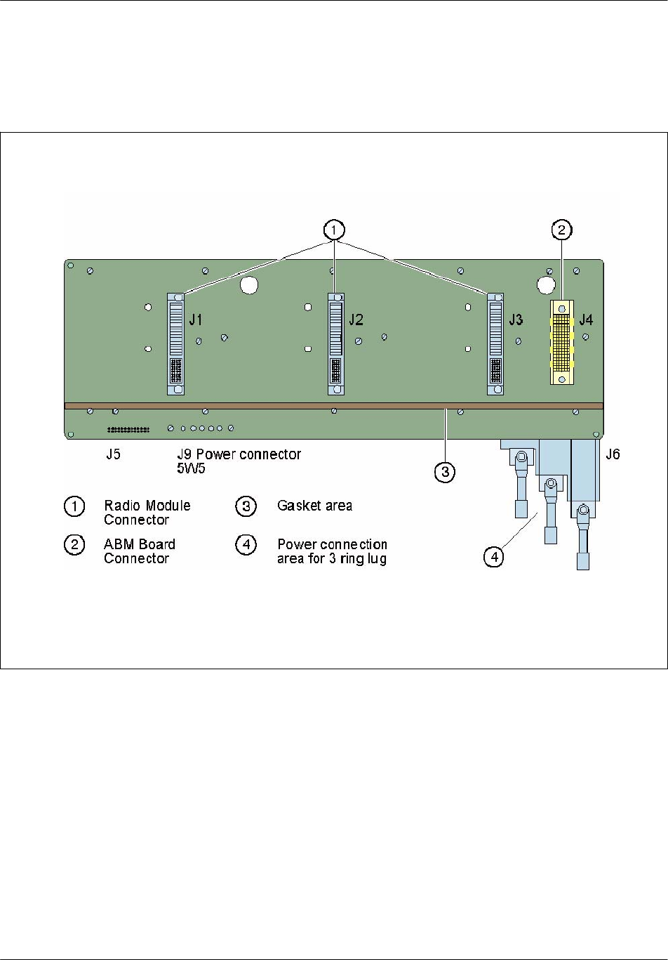
4.1.5 DBP connectors
Figure 4--3 locates all the connectors on the DBP module. They are front panel
connectors, except for J5 and J6, which are located on the rear panel of DBP.
Figure 4--3 DBP connectors location
Table 4--4 indicates the type and the use of the DBP connectors.

BTS18000 modules descriptionNortel Networks Confidential 4--7
BTS18000 Reference Manual
Copyright ©2002--2005 Nortel Networks
DBP connectors Use Type
J1 Connection to RM0
F
C
I
P
o
w
e
r
B
l
a
d
e
c
o
n
n
e
c
t
o
r
:
J2 Connection to RM1
F
C
I
P
o
w
e
r
B
l
a
d
e
c
o
n
n
e
c
t
o
r
:
4x10 pins array (1A to 10D) +
J3 Connection to RM2
p
y
(
)
6 power contacts (P1 to P6)
J4 Connection to ABM HM1 120 pins male
J5 (rear panel) Connection to IBP 2x13 pins array male
J6 (rear panel) Power SUBD 5W5 male
Table 4--4 DBP connectors type and use
4.1.6 Digital signals
The modules are inter--connected through the IBP and the DBP via controlled
impedance Printed Circuit Board (PCB) traces. Signals routed through the
backplane between the modules include:
E1/T1 links between IFM and ICM operating at up to 4.096 MHz,
Local, point--to--point LVDS links between ABM and RMs, and between RMs,
operating at up to 100 MHz,
I2C clock and data using Low--Voltage Transistor--Transistor Logic (LVTTL)
operating at 100 Kbps,
Static LVTTL signals (rack and slot Id, presence detection, status and reset
signals, remote power supplies...),
ICM redundancy,
External synchro,
Inter IBP signals.
4.1.7 Power signals
A three--wire DC power bus carries the --48V or +24V DC power and ground from
the radio DC breaker module to the RMs. Another three--wire DC power bus, on the
DBP, carries the --48V or +24V DC power from the digital breaker module to the
ABM,andtotheIFMandICMviatheIBP.
The ABM remotely powers the inventory memories of the other digital modules
with a low drive 3.3V signal routed through the IBP and the DBP.

BTS18000 modules description Nortel Networks Confidential
4--8
PE/DCL/DD/0160
411--9001--160 Standard 15.104/EN June 2005 Copyright ©2002--2005 Nortel Networks
4.2 Interface Module (IFM)
The IFM is only used in the BTS18000 base cabinet. It is not present in theextension
cabinets. The IFM is composed of a single passive board with connections on the
IBP and on the front panel.
4.2.1 Main functions
The IFM provides connectivity and secondary protection (the level of protection
depends on the type of board, see Section 4.2.2 “Types of IFM board”)onthePCM
links. It provides:
E1 (120 ohms) or T1 (100 ohms) links from the Abis (front panel) with
secondary protection to the local ICM (back panel) and the redundant ICM
(cross--connect connector on front panel).
additional E1/T1 links from the other IFM (cross--connect connector on front
panel) to the local ICM (back panel).
The IFM also provides detection for this additional Abis link to the ICM.
external synchronization link from external source (CMCF phase 2 or GPS
antenna, on the front panel) to the local ICM (back panel) and the remote ICM
(cross--connect connector on front panel).
The active ICM provides an RS422 receive link to the GPS antenna, and retrieves
PPS synchro input from the antenna. The IFM provides antenna detection to both
ICMs.
cross--connect link between the remote ICM (cross--connect connector on front
panel) and the local one (back panel). This link conveys detection,
active/passive, synchro and signaling signals between both ICMs.
the ICM with several status signals (GPS antenna presence, redundancy status).
the ABM with a board presence detection signal and an I2C
Electrically--Erasable Programmable Read--Only Memory (EEPROM) for
inventory. This memory contains factory data and is remotely powered by the
ABM.
Note: The IFM does not provide the ICM with the link type (E1 or T1) detection.
The selection of E1 or T1 mode must be performed via commissioning
switches inside ICM (see Section 4.3.9.1).

BTS18000 modules descriptionNortel Networks Confidential 4--9
BTS18000 Reference Manual
Copyright ©2002--2005 Nortel Networks
4.2.2 Types of IFM board
There are two types of IFM board:
IFM
IFM1
Each board has a different PEC/CPC code (for these codes, see the replacement
procedure in NTP < 162 >).
4.2.2.1 IFM board
The IFM board provides a level of secondary protection greater than or equal to that
provided by a CSU (Channel Service Unit). Consequently, IFM is the appropriate
board to use if a CSU is not being used to provide protection. The name on this board
is IFM.
4.2.2.2 IFM1 board
The IFM1 board provides a lower level of secondary protection than that provided
by the IFM board. If a CSU (Channel Service Unit) is being used to provide
protection, then the IFM1 board can be used instead of the IFM board. The name
on this board is IFM1.
4.2.2.3 Terms used in this NTP
Except for the level of secondary protection and the names that appear on the
boards, the two types of IFM board are identical. Throughout this NTP, the term
“IFM” is used in text and graphics. You should interpret this as a generic term that
covers both types of IFM board. If it is necessary to distinguish between the two
types of IFM board, then this is stated explicitly in the text.
4.2.2.4 Location in cabinet
The BTS18000 cabinet includes:
one mandatory even IFM (IFM--even), located:
•
in the upper shelf, for BTS18010 cabinet,
•
in the left shelf, for BTS18020 cabinet.
one optional odd IFM (IFM--odd), located:
•
in the bottom shelf, for BTS18010 cabinet,
•
in the right shelf, for BTS18020 cabinet.
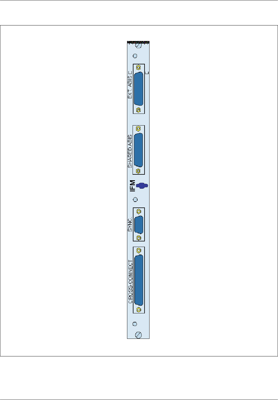
4.2.3 Front panel
Figure 4--4 presents the IFM front panel. Except for the name IFM1, the IFM1
board is identical to the IFM board shown in Figure 4--4.
BTS18000 modules description Nortel Networks Confidential
4--10
PE/DCL/DD/0160
411--9001--160 Standard 15.104/EN June 2005 Copyright ©2002--2005 Nortel Networks
Figure 4--4 IFM front panel

BTS18000 modules descriptionNortel Networks Confidential 4--11
BTS18000 Reference Manual
Copyright ©2002--2005 Nortel Networks
4.2.4 Physical and electrical characteristics
Module
name
Height
(mm)
Width
(mm)
Depth
(mm)
Weight
(Kg)
IFM 335 25 410 <1
Table 4--5 IFM dimensions and weight
Maximum number per cabinet: 2, in the base cabinet only.
Maximum power consumption: 0 W.
Associated breaker:
Digital breaker (BTS18010),
CB3 digital breaker (BTS18020).
BTS18000 modules description Nortel Networks Confidential
4--12
PE/DCL/DD/0160
411--9001--160 Standard 15.104/EN June 2005 Copyright ©2002--2005 Nortel Networks
4.2.5 Interface description
4.2.5.1 Connectors
Table 4--6 indicates the type and the use of the IFM connectors. They are front panel
connectors, except for J4, which is a back panel connector.
Abis connectors Use Type
J0 E1/T1 links to Abis network -- EXT ABIS SUBD 25 pins male
J1 E1/T1 links to ICM -- SHARED ABIS SUBD HD 44 pins female
External synchro connector Use Type
J3 External synchro: GPS clock, detect,
Gnd, synchro RS422 -- SYNC SUBD 9 pins female
Cross--connect connector Use Type
J2 Cross link:
synchro, activity detection, signaling
between ICMs -- CROSS--CONNECT
SUBD HD 62 pins female
Signal connector (back panel) Use Type
J4 Signals from Abis and Cross--connect
connectors, I2C to ABM HM1 210 pins female
Table 4--6 IFM connectors type and use
The Abis front panel connector provide the following signals:
four E1/T1 main bidirectional links.
The External Synchro front panel connector provides the following signals:
cable detection,
signaling bidirectional link to GPS antenna or CBCF link,
PPS clock from GPS antenna or 8kHz synchro from CBCF.
The Shared Abis front panel connector provide the following signals:
four E1/T1 bidirectional links from secondary protection cell to other IFM,
four E1/T1 bidirectional links from other cell to local ICM.

BTS18000 modules descriptionNortel Networks Confidential 4--13
BTS18000 Reference Manual
Copyright ©2002--2005 Nortel Networks
The Cross--connect front panel connector provides the following signals:
cable detection,
active/passive signals,
signaling bidirectional link between ICMs,
synchro signals from active to passive,
external synchro signals share between IFMs.
The back panel connector provides the following signals:
all signals from Abis front panel connectors (secondary protected),
all signals from Cross--connect front panel connectors (except the protected four
E1/T1toremoteIFM),
board presence, I2C bus and address, EEPROM power supply.
4.2.6 LEDs behavior
There is no LED on the IFM.

BTS18000 modules description Nortel Networks Confidential
4--14
PE/DCL/DD/0160
411--9001--160 Standard 15.104/EN June 2005 Copyright ©2002--2005 Nortel Networks
4.3 Interface Control Module (ICM)
The ICM is only used in the BTS18000 base cabinet. It is not present in the extension
cabinets. It is designed to manage the whole BTS18000 site in simplex or redundant
mode.
The ICM is composed of a single board with connections on the IBP and on the front
panel.
4.3.1 Main functions
The ICM in simplex mode covers the functions related to a complete site including:
support of drop--and--insert facilities for the PCM links with the BSC,
reference clock for the air interface, synchronized on the Abis PCM interface, a
synchronizing BTS or a GPS antenna,
GSM_TIME calculations with possible network synchronization,
switching of PCM slots,
conversion of electrical signals, from external to internal PCM data formats,
concentration of the data flow of the BTS,
configuration and supervision of all the modules.
Redundancy can optionally be introduced using two ICMs in the cabinet: one even
ICM (ICM0) and one odd ICM (ICM1). In such a mode, called duplex, there is one
active ICM and one passive ICM.
The even ICM (ICM0) shall be equipped in simplex mode and is the default active
ICM at start up.
In duplex mode:
the active ICM is the currently operational one, as opposed to the passive one,
the passive ICM is the currently non operational one, as opposed to the active
one.
The redundancy is static. If the passive ICM traps, the swap from passive to active
occurs, but the traffic is lost and the newly active ICM can accept new traffic.
Note: ICM chain switching may disturb punctually the Abis lines, as line
transceivers of both boards share the same signals. This disturbance may
last several microseconds to several milliseconds, depending on the
hardware implementation. These characteristics are also met on the BSC
interface boards.

BTS18000 modules descriptionNortel Networks Confidential 4--15
BTS18000 Reference Manual
Copyright ©2002--2005 Nortel Networks
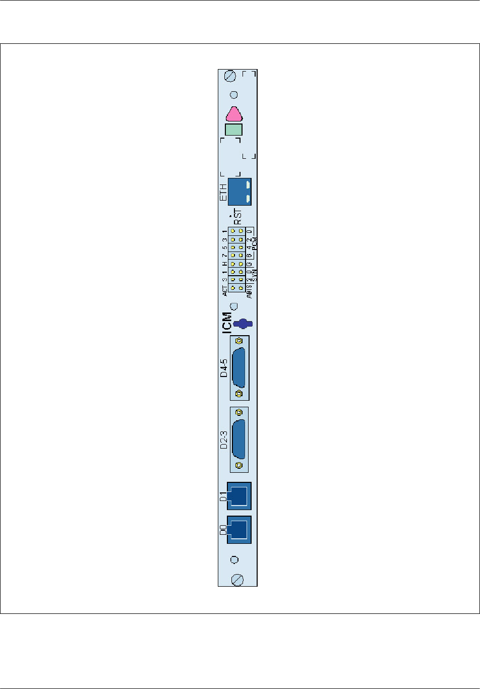
4.3.2 Front panel
Figure 4--5 presents the ICM front panel.
BTS18000 modules description Nortel Networks Confidential
4--16
PE/DCL/DD/0160
411--9001--160 Standard 15.104/EN June 2005 Copyright ©2002--2005 Nortel Networks
Figure 4--5 ICM front panel
BTS18000 modules descriptionNortel Networks Confidential 4--17
BTS18000 Reference Manual
Copyright ©2002--2005 Nortel Networks
4.3.3 Physical and electrical characteristics
Module
name
Height
(mm)
Width
(mm)
Depth
(mm)
Weight
(Kg)
ICM 335 25 410 <1
Table 4--7 ICM dimensions and weight
Maximum number per cabinet: 2, in the base cabinet only.
Maximum power consumption: 30 W.
Input voltage range: 20 V -- 60 V.
Associated breaker:
Digital breaker (BTS18010),
CB3 digital/RICO/user breaker (BTS18020).
4.3.4 Interface description
4.3.4.1 Connectors
Table 4--8 indicates the type and the use of the ICM connectors. They are front panel
connectors, except for J10, J11 and J12, which are back panel connectors.
Debug connector Use Type
J2 Ethernet / RS232 debug -- ETH 8pinsRJ45female
Signal connectors (front panel) Use Type
J0 D link in the base cabinet (ABM) -- D0
1
0
p
i
n
s
R
J
4
5
f
e
m
a
l
e
J1 D link in the base cabinet (ABM) -- D1 10 p
i
ns
R
J
45
f
ema
l
e
J23 D link for one extension cabinet -- D2--3
S
U
B
D
H
D
2
6
p
i
n
s
f
e
m
a
l
e
J45 D link for one extension cabinet -- D4--5
S
U
B
D
H
D
26 p
i
ns
f
ema
l
e
Signal connectors (back panel) Use Type
J10 Power HM130pinsfemale
J12 Spare links HM1 120 pins female
J11 E1/T1 links, GPS or external synchro HM1 210 pins female
Table 4--8 ICM connectors type and use

BTS18000 modules description Nortel Networks Confidential
4--18
PE/DCL/DD/0160
411--9001--160 Standard 15.104/EN June 2005 Copyright ©2002--2005 Nortel Networks
The front panel Debug connector provides the following signals:
Reset push button,
debug access (RS232 monitor + 10/100bT).
The six D link front panel connectors provide the following LVDS signals:
clock, synchro and full duplex bi--directional data at 16.384Mbsp. Those signals
are hot pluggable.
The back panel power connector provides:
24/48V wide input range floating supply.
The Signal back panel connectors provide:
eight E1/T1 main bi--directional links with IFM,
all ICM GPS signals (cable detection, power to the antenna, signaling
bi--directional link to antenna, PPS clock from antenna), or external
synchronization signals (SY and MICR from CBCF),
all cross connect signals with IFM (cable detection, active/passive signals,
signaling bi--directional link between ICMs, synchro signals from active to
passive),
board presence, I2C bus, address and power.
BTS18000 modules descriptionNortel Networks Confidential 4--19
BTS18000 Reference Manual
Copyright ©2002--2005 Nortel Networks
4.3.5 ICM Corporate LEDs behavior
As shown on Figure 4--6, an upper triangle--shaped red LED and a lower
rectangle--shaped green LED are used to indicate the status for some BTS18000
modules. See Figure 4--7 for the ICM detailed status information.
Figure 4--6 Corporate LEDs
Green LED Red LED ICM status
switched off switched off Sleep, un--powered or not inserted
(default hardware value)
JY
starting, BISTs in progress
J
switched off normal operation -- no faults
J
blinking module is possibly partially faulty -- ICM
installation problem
switched off
Y
alarm status: abnormal operation -- must be
removed and replaced
blinking
Y
or switched off wait for ICM connection -- used on passive ICM
blinking blinking internal downloading -- used on passive ICM
Figure 4--7 ICM Corporate LEDs behavior

BTS18000 modules description Nortel Networks Confidential
4--20
PE/DCL/DD/0160
411--9001--160 Standard 15.104/EN June 2005 Copyright ©2002--2005 Nortel Networks
4.3.6 ICM specific LEDs behavior
Table 4--9 gives detailed information on ICM specific LEDs behavior. All these
LEDs are OFF when the ICM is un--powered. All these LEDs are amber during
BISTs.
LED name Color Meaning
PCMx
(x = 0 to 7)
F
F
F
8 PCM status LEDs (one per PCM):
-- Green: the PCM is OK
-- Red: the PCM is in fault
-- Amber: the PCM is in test
G
(GPS)
F
F
F
1 GPS or external synchro status LED:
-- OFF: no external synchronization
-- Green: GPS synchronization
-- Red: bad external synchronization signal
-- Amber: master BTS synchronization
SYN
(synchro)
F
Four LEDs for synchronizing source: one out of the 8 PCMs
or external synchronization (in that case the 4 LEDs are ON)
-- s e e Table 4--10 --
H
(holdover)
F
One LED for synchro locked status:
-- ON on active ICM: un--locked or holdover indication
-- ON on passive ICM: un--locked indication
-- OFF: synchro is locked on external source
ACT
(activity)
F
F
One LED for ICM Passive or Active Status:
-- Green: the ICM is active
-- OFF: the ICM is passive
-- Red on both ICMs: the simplex or duplex configuration
cannot be determined, both ICMs are in faulty passive state
ABIS
F
Level--2 status with BSC:
-- ON: level--2 is OK
-- Blinking: downloading in progress
-- OFF: no Level--2 with the BSC
Table 4--9 ICM specific LEDs behavior

BTS18000 modules descriptionNortel Networks Confidential 4--21
BTS18000 Reference Manual
Copyright ©2002--2005 Nortel Networks
4.3.6.1 ICM SYN LEDs behavior
The behavior of the four LEDs for synchronization source is described in
Table 4--10.
SYNCHRO SOURCE 0 1 2 3
PCM 0
F
switched off switched off switched off
PCM 1 switched off
F
switched off switched off
PCM 2
F F
switched off switched off
PCM 3 switched off switched off
F
switched off
PCM 4
F
switched off
F
switched off
PCM 5 switched off
F F
switched off
PCM 6
F F F
switched off
PCM 7 switched off switched off switched off
F
external source (GPS,
master BTS)
F F F F
holdover (*)
F
/ switched
off (*)
F
/ switched
off (*)
F
/ switched
off (*)
F
/ switched
off (*)
(*)
In Holdover, the SYN LED indicates the clock source (PCM number) that the syn tries to
use for synchronization. In that case, the holdover LED (H) is ON on the active ICM.
Table 4--10 ICM SYN LEDs behavior
4.3.7 LEDs behavior at active ICM starting up
The specific LEDs behavior, when the active ICM starts up, is as follows:
1
When the BTS18000 is turned on, H (holdover) and ACT (active) LEDs
switch ON.
2
After the Built--in Self Test (BIST) sequence, the ICM searches for
synchronizing with the PCM0 link.
3
When the clock source is found, H LED switches OFF and synchro source
LEDs (SYN) switch ON (see Table 4--10).
Table 4--11 summarizes the behavior of corporate and specific LEDs when active
ICM starts up.
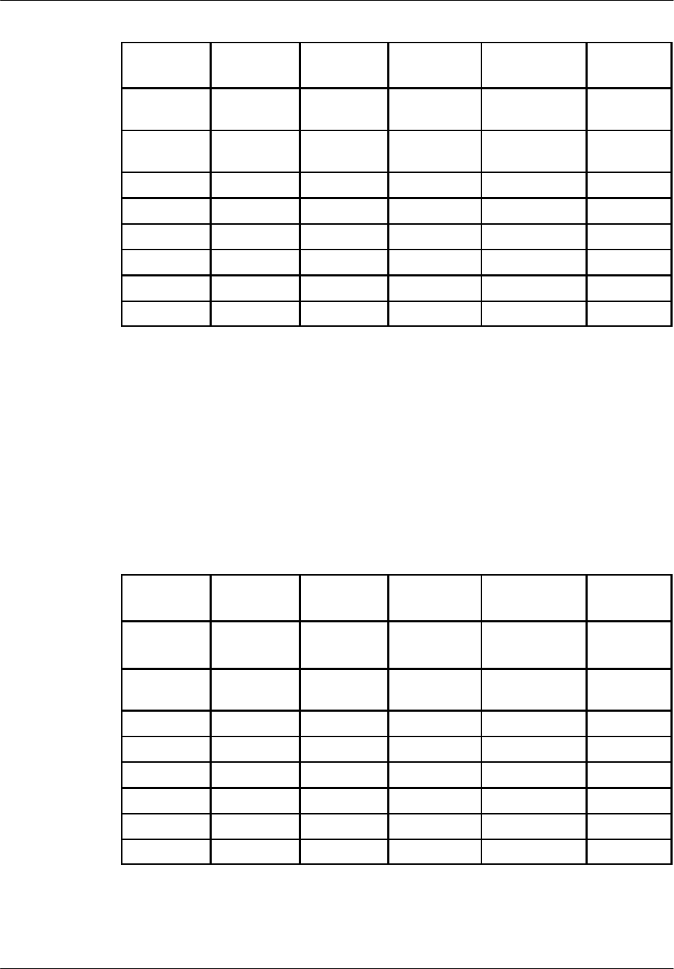
BTS18000 modules description Nortel Networks Confidential
4--22
PE/DCL/DD/0160
411--9001--160 Standard 15.104/EN June 2005 Copyright ©2002--2005 Nortel Networks
ICM boot
sequence ICM BISTs Abis
connection
ICM
downloading
Nominal
operation
triangle
corporate
Y Y
rectangle
corporate
J J J J J
ACT
FF F F
SYN
FF F F
G
F
Abis
FF F
blinking
F
PCMx
FF F F
H
FF
Table 4--11 LEDs behavior at active ICM starting up
4.3.8 LEDs behavior at passive ICM starting up
The passive ICM can be differentiated from the active one thanks to the ACT LED
switched off. The behavior of the SYN and PCM LEDs is the same as for the active
ICM.
Table 4--12 summarizes the behavior of corporate and specific LEDs when passive
ICM starts up.
ICM boot
sequence ICM BISTs Active ICM
connection
Passive ICM
downloading
Nominal
operation
triangle
corporate
Y Y Y
or
switched off
Y
blinking
rectangle
corporate
J J J
blinking
J
blinking
J
ACT
F
SYN
FF F F
G
F
Abis
F
PCMx
FF F F
H
FF
Table 4--12 LEDs behavior at passive ICM starting up
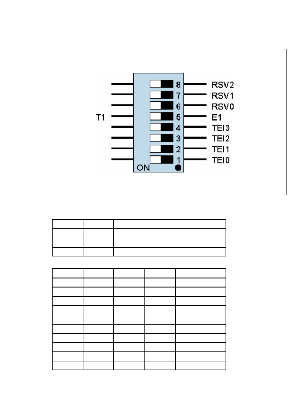
BTS18000 modules descriptionNortel Networks Confidential 4--23
BTS18000 Reference Manual
Copyright ©2002--2005 Nortel Networks
4.3.9 Configuration of the ICM switches for commissioning
4.3.9.1 SW10 switch
Figure 4--8 ICM SW10 switch
E1/T1 RSV0 Frame Format
OFF OFF E1 mode (120 ohms)
OFF ON E1 mode with 75 ohms adapter
ON -- T1 mode (100 ohms)
TEI(3) TEI(2) TEI(1) TEI(0) Site TEI coding
OFF OFF OFF OFF 0
OFF OFF OFF ON 1
OFF OFF ON OFF 2
OFF OFF ON ON 3
OFF ON OFF OFF 4
OFF ON OFF ON 5
OFF ON ON OFF 6
OFF ON ON ON 7
ON OFF OFF OFF 8
ON OFF OFF ON 9
Table 4--13 ICM SW10 switch configuration
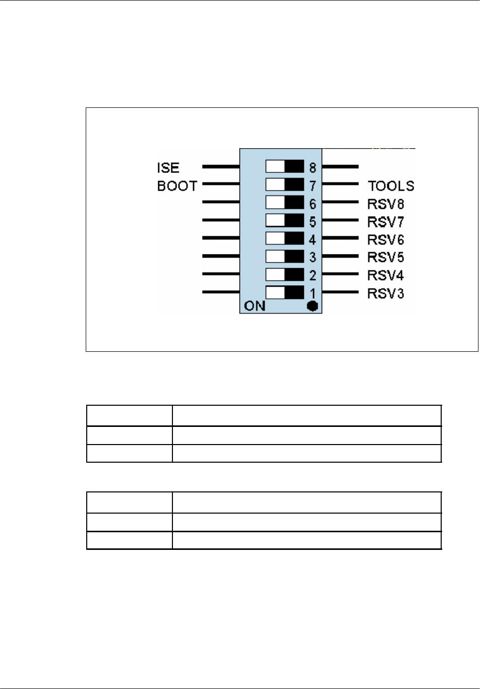
BTS18000 modules description Nortel Networks Confidential
4--24
PE/DCL/DD/0160
411--9001--160 Standard 15.104/EN June 2005 Copyright ©2002--2005 Nortel Networks
An ICM board cannot start if its TEI value is out of the range given in Table 4--13.
Factory setting is TEI equal to zero. RSV(0--2) are unused (default value is OFF).
4.3.9.2 SW11 switch
Figure 4--9 ICM SW11 switch
ISE ICM for New--SEB mode
OFF ICM in nominal mode
ON ICM in New--SEB mode if confirmation bit is set in FPGA
BOOT/TOOLS Processor booting mode
OFF Require emulator probe connected
ON Booting in Flash memory (nominal mode)
Table 4--14 ICM SW11 switch configuration
RSV(3--8) are unused (default value is OFF). Passive and active ICM must have the
same switches configuration. Otherwise, both ICM are in the ”passive partially
faulty” state: the corporate green LED is ON and the red one is blinking.
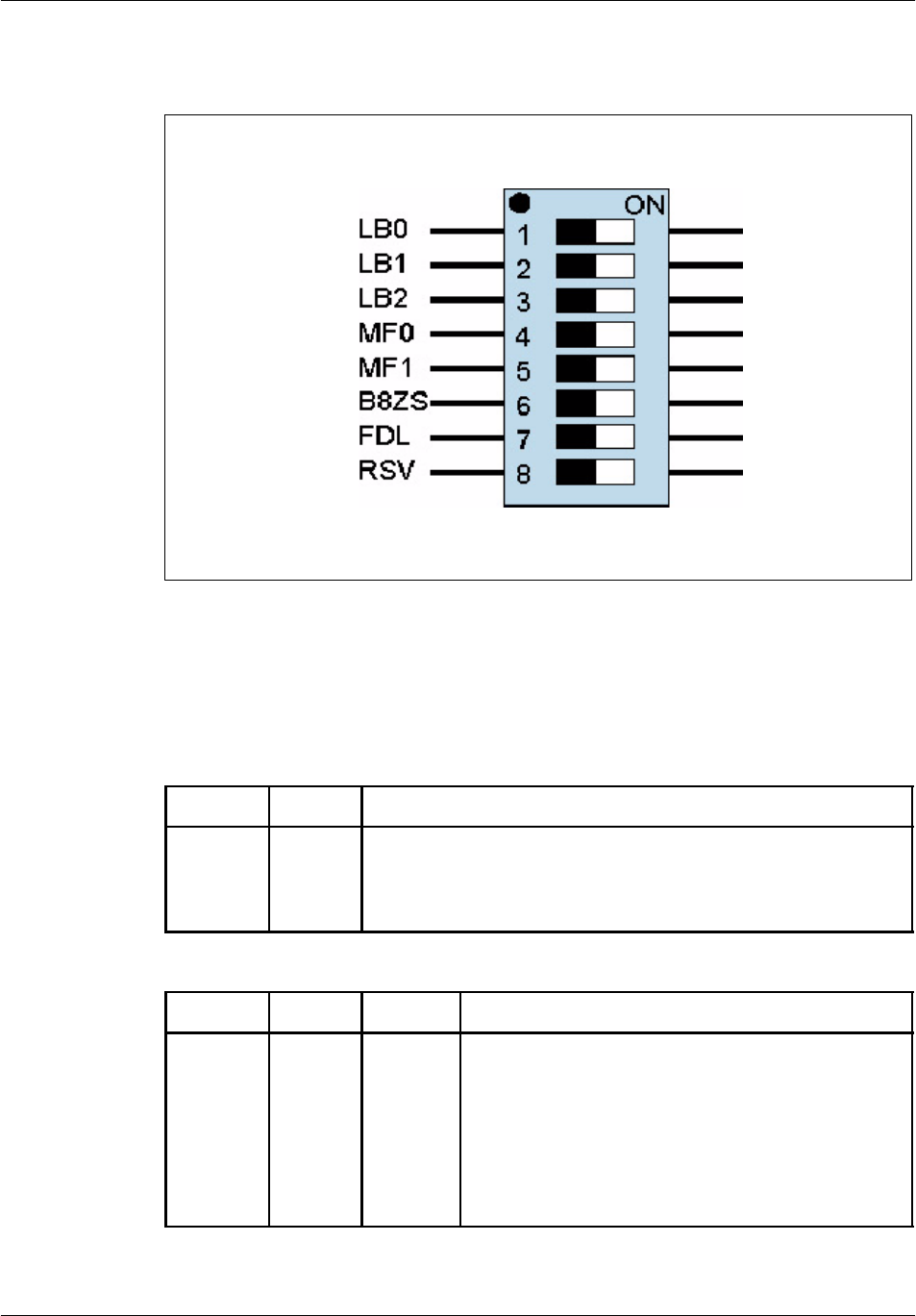
BTS18000 modules descriptionNortel Networks Confidential 4--25
BTS18000 Reference Manual
Copyright ©2002--2005 Nortel Networks
4.3.9.3 SW0--SW7 switches: one per Abis line
Figure 4--10 ICM Abis switch
The E1 or T1 mode selection is performed thanks to switch SW10 (see Table 4--13).
Refer to Table 4--15 and Table 4--16 for detailed information on E1/T1
configurations of the ICM Abis switches.
MF1 MF0 Frame Format
OFF
OFF
ON
ON
OFF
ON
OFF
ON
12--frame multi--frame (Super--Frame)
Extended Super--frame (ESF) with CRC6 check/generation
Extended Super--frame (ESF) without CRC6 check/generation
Not used
LB2 LB1 LB0 Line Build--Out
OFF
OFF
OFF
OFF
ON
ON
ON
ON
OFF
OFF
ON
ON
OFF
OFF
ON
ON
OFF
ON
OFF
ON
OFF
ON
OFF
ON
length = 000..133ft (0.6dB -- DSX--1) / 0.0dB (DS1)
length = 133..266ft (1.2dB -- DSX--1)
length = 266..399ft (1.8dB -- DSX--1)
length = 399..533ft (2.4dB -- DSX--1)
length = 533..655ft (3.0dB -- DSX--1)
--7.5dB (DS1)
--15.0dB (DS1)
--22.5dB (DS1)
BTS18000 modules description Nortel Networks Confidential
4--26
PE/DCL/DD/0160
411--9001--160 Standard 15.104/EN June 2005 Copyright ©2002--2005 Nortel Networks
B8ZS Line code
OFF
ON
AMI coding
B8ZS coding
Table 4--15 ICM Abis switch -- T1 configuration
FDL (Facility Data--Link) and RSV are not used. Their default value is OFF.
MF1 MF0 Frame Format
OFF OFF Single frame
OFF ON Multi--frame with CRC4 decoding
ON OFF Multi--frame without any CRC4 decoding
ON ON Automatic multi--frame with CRC4 decoding
LB2 LB1 LB0 Line Build--Out is NOT used
OFF OFF OFF Default value
B8ZS Line code
OFF HDB3 coding
ON AMI coding (provision)
Table 4--16 ICM Abis switch -- E1 configuration
FDL (Facility Data--Link) and RSV are not used. Their default value is OFF.

BTS18000 modules descriptionNortel Networks Confidential 4--27
BTS18000 Reference Manual
Copyright ©2002--2005 Nortel Networks
4.4 Alarms and Bridge Module (ABM)
One ABM is used in each BTS18000 digital rack. Therefore, a BTS18000 cabinet
contains two ABMs (even and odd).
The ABM is composed of a single board with connections on the DBP and on the
front panel.
4.4.1 Main functions
4.4.1.1 Alarm collector function
The ABM alarm collector function performs the following operations under the
ICM control:
Detection of cabinet alarms:
•
door status,
•
BTS18020 cabinet User Rack and ADU.
Presence detection of the digital rack, combiner rack and other cabinet modules:
•
digital rack modules: IFM, ICM and the three RMs,
•
RF combiners: DDM, TX filter (TXF), DDM (H2) and TXF (H2),
•
cabinet modules: BTS18010 SICS, BTS18020 ECU and UCPS.
Inventory of the digital rack, combiner rack and other cabinet modules:
•
IFM, ICM, and the three RMs, via the I2C bus,
•
DDM, TXF, DDM (H2) and TXF (H2), via the pseudo I2C over RS422,
•
BTS18010 SICS and BTS18020 ECU, via the pseudo I2C over RS422,
•
UCPS modules, through a dedicated protocol over RS422.
Alarm polling of the radio coupling modules, through the pseudo I2C bus over
RS422:
•
Low Noise Amplifier (LNA) over--current detection in the DDMs,
•
VSWR alarms and associated setting of thresholds in the DDMsand TX filters
with the VSWR option.
Alarm polling of the cooling system modules, through the pseudo I2C bus over
RS422:
•
BTS18010 SICS blowers, filter, power and control board status,
•
BTS18020 ECU blowers, filter, damper, heater, power and control board
status.

BTS18000 modules description Nortel Networks Confidential
4--28
PE/DCL/DD/0160
411--9001--160 Standard 15.104/EN June 2005 Copyright ©2002--2005 Nortel Networks
Alarm polling of the BTS18020 cabinet UCPS:
•
AC monitoring,
•
DC monitoring,
•
breakers status,
•
battery status.
Optional external alarm detection (up to eight customer alarms per ABM).
Remote control drive (up to two remote controls per ABM).
4.4.1.2 Bridge function
The ABM assures bridge functions between several interfaces:
On one side, it manages interface with ICM (one front panel D link or two in case
of ICM redundancy),
On the other side, the bridge manages one internal E link for ABM alarm function
and three E links to the RM modules.
The traffic management between all interfaces is automatic and does not need
specific configuration. It is kept available whatever the module software status, as
long as power is on.
4.4.2 Front panel
Figure 4--11 presents the ABM front panel.
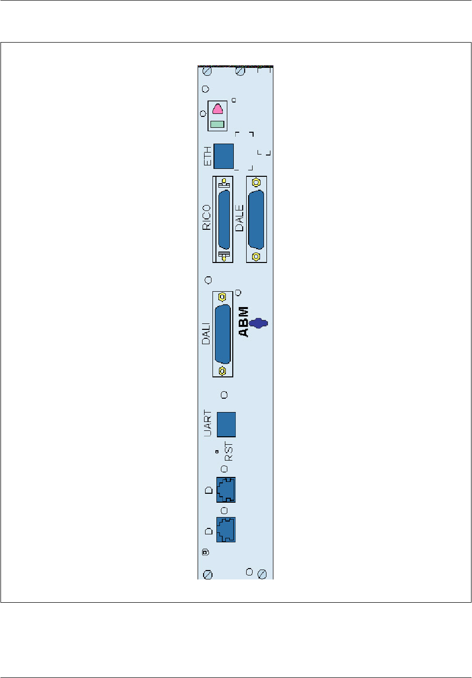
BTS18000 modules descriptionNortel Networks Confidential 4--29
BTS18000 Reference Manual
Copyright ©2002--2005 Nortel Networks
Figure 4--11 ABM front panel

BTS18000 modules description Nortel Networks Confidential
4--30
PE/DCL/DD/0160
411--9001--160 Standard 15.104/EN June 2005 Copyright ©2002--2005 Nortel Networks
4.4.3 Physical and electrical characteristics
Module
name
Height
(mm)
Width
(mm)
Depth
(mm)
Weight
(Kg)
ABM 335 50 410 <1
Table 4--17 ABM dimensions and weight
Maximum number per cabinet:
2, in standard BTS18000 cabinet,
3, in MCPA BTS18020 cabinet.
Maximum power consumption: 15 W.
Associated breaker: digital breaker.
4.4.4 Interface description
4.4.4.1 Connectors
Table 4--18 indicates the type and the use of the ABM connectors. They are front
panel connectors, except for J10, which is a back panel connector.
Debug connector Use Type
J6 Ethernet / RS232 debug -- ETH 8pinsRJ45female
Cabinet interface connector Use Type
J21 I2C data / clock, combiner detection,
cabinet detection -- RICO SCSI 50 pins female
External alarm connector Use Type
J21 External alarm, remote control -- DALE SUBD 25 pins female
Internal alarm connector Use Type
J20 Internal alarm -- DALI SUBD 25 pins male
UART connector Use Type
J22 UART link -- UART 6pinsRJ11female
Signal connectors (front panel) Use Type
J14 D link (0 or 1) -- D
1
0
p
i
n
s
R
J
4
5
f
e
m
a
l
e
J15 D link (0 or 1) -- D 10 p
i
ns
R
J
45
f
ema
l
e
Signal connector (back panel) Use Type
J10 Three E links, detection, inventory HM1 120 pins female
Table 4--18 ABM connectors type and use

BTS18000 modules descriptionNortel Networks Confidential 4--31
BTS18000 Reference Manual
Copyright ©2002--2005 Nortel Networks
The front panel Debug connector provides the following signals:
Reset push button,
debug access (RS232 monitor + 10/100bT).
The Signal front panel connectors provide:
one D link connectivity from ICM, in case of simplex mode, or two D links
connectivity from ICM, in case of redundant mode,
one spare link over RS422 for future use.
The Internal alarm front panel connector provides:
even or odd position detection from Radio InterCO panel,
detection, inventory and alarm of the radio combiners and cabinet modules
through booleans, I2C and UART busses,
collection of cabinet Boolean alarms.
The External, user alarms front panel connector provides:
collection of external protected Boolean alarms and remote control.
The back panel power connector provides:
24/48V wide input range floating supply.
The Signal back panel connector provides:
three point--to--point E links to the RMs,
board presence detection, remote power I2C inventory to all digital modules
(including ABM itself).
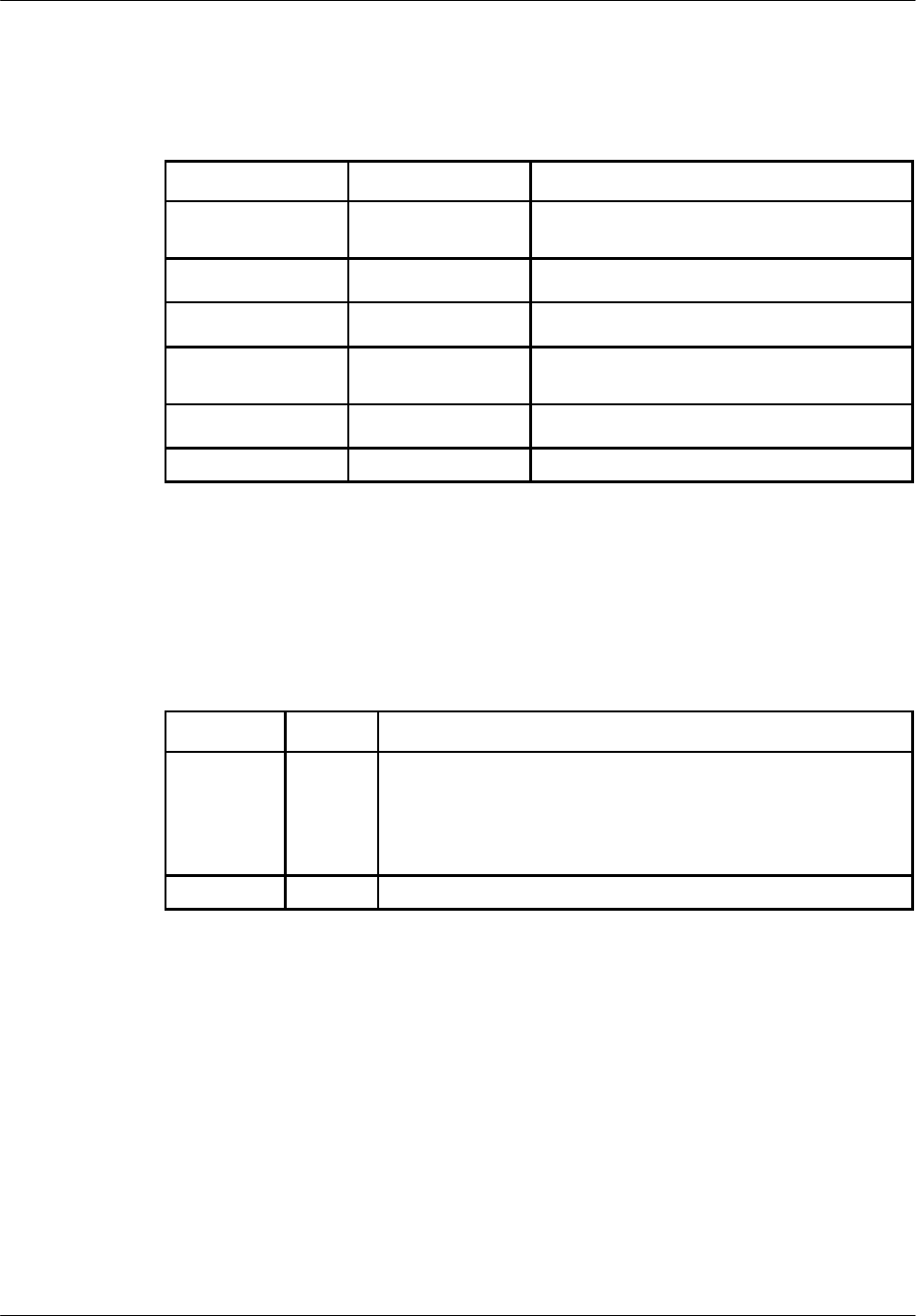
BTS18000 modules description Nortel Networks Confidential
4--32
PE/DCL/DD/0160
411--9001--160 Standard 15.104/EN June 2005 Copyright ©2002--2005 Nortel Networks
4.4.5 ABM corporate LEDs behavior
Table 4--19 gives ABM detailed status information.
Green LED Red LED ABM status
switched off switched off un--powered or not inserted
(default hardware value)
JY
starting, BISTs in progress
J
switched off normal operation -- no faults
switched off
Y
alarm status: abnormal operation -- must
be removed and replaced
blinking
Y
or switched off wait for ICM connection
blinking blinking internal downloading
Table 4--19 ABM corporate LEDs behavior
4.4.6 ABM specific LEDs behavior
Table 4--20 gives detailed information on ABM specific LEDs behavior.
LED Name Color Meaning
D
F
2 LEDs for D activity
ON: when the connection to active ICM through the D link
related to the LED is correctly established
Only one of the 2 D LEDs can be ON
UART
F
ON: UART activity (reserved for future use)
Table 4--20 ABM specific LEDs behavior

BTS18000 modules descriptionNortel Networks Confidential 4--33
BTS18000 Reference Manual
Copyright ©2002--2005 Nortel Networks
4.4.7 LEDs behavior at ABM starting up
Table 4--21 gives the behavior of corporate and specific LEDs when ABM starts up.
ABM boot
sequence ABM BIST Active ICM
connection
ABM
downloading
Nominal
operation
triangle
corporate
Y Y Y
or
switched off
Y
blinking
rectangle
corporate
J J J
blinking
J
blinking
J
D
F F F
Table 4--21 LEDs behavior at ABM starting up
Note: External alarms do not impact the ABM corporate LEDs management
(these LEDs only indicate ABM board alarms).

BTS18000 modules description Nortel Networks Confidential
4--34
PE/DCL/DD/0160
411--9001--160 Standard 15.104/EN June 2005 Copyright ©2002--2005 Nortel Networks
4.5 Radio Module (RM)
4.5.1 Main functions
The RM is a complete GSM/GPRS/EDGE transmitter/receiver. The RM is in charge
of all processing related to the GSM TDMAs. It is designed to support three TDMA
(GSM or EDGE). It is logically equivalent to three TRXs (0, 1 and 2).
The RM may operate:
on a one--sector basis (three carriers per sector, O3 mode),
on a three--sector basis (one carrier per sector, S111 mode).
Maximum configurations for BTS18000 mono--cabinet with RM are S666, O18
and S99.
4.5.1.1 RX splitter function
The RM integrates a RX splitter function. It is inserted between the DDM and RM
RX paths (main and diversity). It allows splitting DDM RX outputs in order to reach
maximum configurations (one input to three outputs split for main and diversity
paths).
In order to fit both RM configurations (S111 and O3), this function is configurable
by RF switches. The commands of switches are provided by the DDM (DC
command multiplexed on RF signals on DDM RX outputs and automatic RX
splitter configuration by RF connection).
4.5.2 Front panel
Figure 4--12 presents the RM front panel.
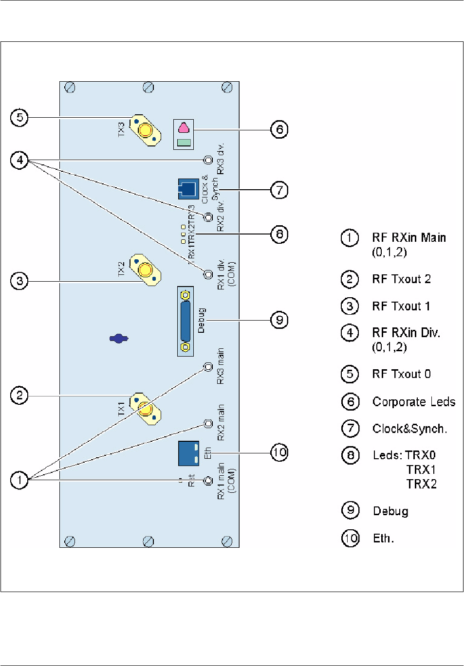
BTS18000 modules descriptionNortel Networks Confidential 4--35
BTS18000 Reference Manual
Copyright ©2002--2005 Nortel Networks
Figure 4--12 RM front panel

BTS18000 modules description Nortel Networks Confidential
4--36
PE/DCL/DD/0160
411--9001--160 Standard 15.104/EN June 2005 Copyright ©2002--2005 Nortel Networks
4.5.3 Physical and electrical characteristics
Module
name
Height
(mm)
Width
(mm)
Depth
(mm)
Weight
(Kg)
RM 335 125 410 19
Table 4--22 RM dimensions and weight
Maximum number per cabinet: 6.
Maximum power consumption: 765 W.
Output power:
The RM output power may vary according to the frequency band. The frequency
variant of the RM is managed by software thanks to RF board frequency variants
detection. Table 4--23 gives the RM output power for all frequency bands.
RM output power GSM900 GSM1800 GSM1900
Typical output power (dBm) 46 44.8 44.8
Typical output power (W) 40 30 30
Variation (dB) +/--0.5 +/--0.5 +/--0.5
Table 4--23 RM output power per frequency band
Associated breaker (one for each group of three RMs):
RF0 and RF1 breakers, for BTS18010 cabinet:
•
RM0, RM1 and RM2 on RF0,
•
RM3, RM4 and RM5 on RF1.
CB1 RF0 and CB2 RF1 breakers, for BTS18020 cabinet:
•
RM0, RM1 and RM2 on RF0,
•
RM3, RM4 and RM5 on RF1.
BTS18000 modules descriptionNortel Networks Confidential 4--37
BTS18000 Reference Manual
Copyright ©2002--2005 Nortel Networks
4.5.4 Interface description
The RM provides the following interfaces:
radio interface:
•
three PA outputs, QN type 50 ohms connectors,
•
six RX inputs (three main, three diversity), QMA type 50 ohms connectors,
digital/power interface on the DBP:
•
24/48V wide range input power feeder,
•
a point--to--point E link to the ABM,
•
board presence detection and inventory I2C link to the ABM,
•
a point--to--point spare link to each of the two other RMs,
debug interface:
•
Reset push button,
•
CPU debug access (RS232 monitor + BDM + 10/100bT),
•
DSP debug access,
•
trace access.
4.5.5 RM corporate LEDs behavior
Table 4--24 gives RM detailed status information.
Green LED Red LED RM status
switched off switched off un--powered or not inserted
(default hardware value)
JY
starting, BISTs in progress
J
switched off normal operation -- no faults
J
blinking module is possibly partially faulty -- TRX(s)
in fault
switched off
Y
alarm status: abnormal operation -- RM is
in fault -- must be removed and replaced
blinking
Y
or switched off wait for ICM connection
Table 4--24 RM corporate LEDs behavior

BTS18000 modules description Nortel Networks Confidential
4--38
PE/DCL/DD/0160
411--9001--160 Standard 15.104/EN June 2005 Copyright ©2002--2005 Nortel Networks
4.5.6 RM specific LEDs behavior
4.5.6.1 Ethernet LEDs behavior
The TX (green) and LI (amber) Ethernet LEDs are on the Ethernet connector.
These LEDs are switched off in nominal mode of operation. They are only used for
debug purposes.
4.5.6.2 TRX LEDs behavior
Table 4--25 gives detailed information on RM TRX LEDs behavior.
LED Name Color Meaning
TRX 0--1--2
F
-- flashes during SPU cluster download
-- blinks until BSC connection, including Abis downloading
-- switched off when TRX is operational
-- switched on when TRX is in fault
Table 4--25 RM TRX 0--1--2 LEDs behavior
4.5.7 LEDs behavior at RM starting up
Table 4--26 gives the behavior of corporate and specific LEDs when RM starts up.
RM
power
up
RM
start
up
RM
BISTs
RM
soft
start
RM soft
init
(1/2)
SPU
load &
start
RM soft
init
(2/2)
Connection
to BCF/Abis
downloading
Nominal
operation
triangle
corporate
Y Y Y Y
rectangle
corporate
J J J J J
blinking
J
blinking
J
blinking
J J
TRX
0--1--2
F F F
blinking
F
blinking
Table 4--26 LEDs behavior at RM starting up

BTS18000 modules descriptionNortel Networks Confidential 4--39
BTS18000 Reference Manual
Copyright ©2002--2005 Nortel Networks
4.6 High Power Radio Module (HPRM)
4.6.1 Main functions
The HPRM is a variant of the RM with only a two--TDMA capacity, but with an
increased output power. It is logically equivalent to two TRXs (0 and 1).
The BTS18000 with HPRM is only available in GSM900 frequency band, as a first
step.
The HPRM can operate on:
one--sector basis (two carriers per sector, O2 mode),
two--sector basis (one carrier per sector, S11 mode).
Maximum configurations for BTS18000 mono--cabinet with HPRM are S444, O12
and S66.
4.6.2 Front panel
Figure 4--13 presents the HPRM front panel.
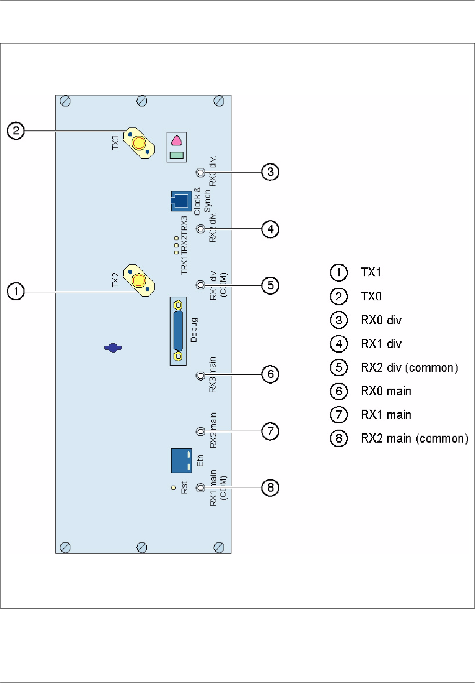
BTS18000 modules description Nortel Networks Confidential
4--40
PE/DCL/DD/0160
411--9001--160 Standard 15.104/EN June 2005 Copyright ©2002--2005 Nortel Networks
Figure 4--13 HPRM front panel

BTS18000 modules descriptionNortel Networks Confidential 4--41
BTS18000 Reference Manual
Copyright ©2002--2005 Nortel Networks
4.6.3 Physical and electrical characteristics
Module
name
Height
(mm)
Width
(mm)
Depth
(mm)
Weight
(Kg)
HPRM 335 125 410 19
Table 4--27 HPRM dimensions and weight
Maximum number per cabinet: 6.
Maximum power consumption: 540 W.
Output power: 60W/45W (GMSK/8--PSK) +/-- 0.5 dB.
Associated breaker (one for each group of three HPRMs):
RF0 and RF1 breakers, for BTS18010 cabinet,
CB1 RF0 and CB2 RF1 breakers, for BTS18020 cabinet.
4.6.4 Interface description
The HPRM provides the following interfaces:
radio interface:
•
two PA outputs, QN type 50 ohms connectors,
•
six RX inputs (three main, three diversity), QMA type 50 ohms connectors,
digital/power interface on the DBP (the same as for RM),
debug interface (the same as for RM).
4.6.5 HPRM LEDs behavior
The HPRM LEDs behavior is identical to the RM LEDs behavior. The TRX2 LED
of a HPRM remains always OFF. It is only tested during BISTs.

BTS18000 modules description Nortel Networks Confidential
4--42
PE/DCL/DD/0160
411--9001--160 Standard 15.104/EN June 2005 Copyright ©2002--2005 Nortel Networks
4.7 Dual Duplexer Module (DDM)
The operator can use different types of couplers to couple the PAs to the antennas
and to combine the RX and TX paths:
duplexers,
transmit filters,
hybrid combiners.
These couplers can be found in the following BTS18000 modules:
DDM or DDM with optional H2 coupling, both including an optional VSWR
meter,
TXF or TXF with optional H2 coupling, both including an optional VSWR
meter.
4.7.1 Main functions
The DDM allows to share TX and RX signals on a same antenna. The DDM is aimed
at providing:
TX filtering (noise suppression),
RX filtering (noise suppression),
TX to RX isolation,
front end low noise amplification for the receive chain.
The DDM provides two separate RX paths with four outputs per chain. It also
provides two transmit inputs (two transmit carrier’s capacity). The DDM is used in
a sector basis with one duplexer for main receive path and the other one for diversity
receive path.
4.7.1.1 H2 coupling option
In addition, in order to increase the transmit capacity of the DDM, integrated 2--way
hybrid combiners (H2 coupling) are proposed as an option for the DDM. These
combiners can be by--passed. A front panel switch allows informing the system of
the current DDM H2 configurations (2--way hybrid by--passed or not).
4.7.1.2 VSWR meter option
As an option, the DDM integrates a VSWR meter on both antenna accesses. This
VSWR meter provides three levels of alarms. The corresponding thresholds of
alarms are settable on site, through DDM front panel switches.
The DDM provides a presence detection signal to the ABM. The DDM is also
connected to the ABM through a I2C bus. This bus allows ABM to collect alarms,
inventory information, and to read VSWR thresholds settings.
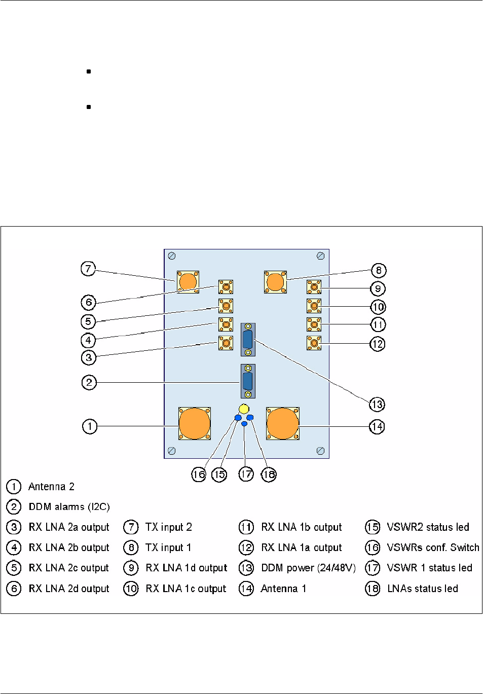
BTS18000 modules descriptionNortel Networks Confidential 4--43
BTS18000 Reference Manual
Copyright ©2002--2005 Nortel Networks
The DDM operates on 24V/--48V main power supply through the RICO board. In
addition, the DDM provides the RICO board with:
a DC signal of 3.3V, in order to power supply the inventory circuitry of the
associated SICS (BTS18010) or ECU (BTS18020),
a DC signal of 5V, in order to power supply the associated TXF (VSWR meter
and inventory circuitry).
4.7.2 Front panel
4.7.2.1 DDM
Figure 4--14 DDM front panel
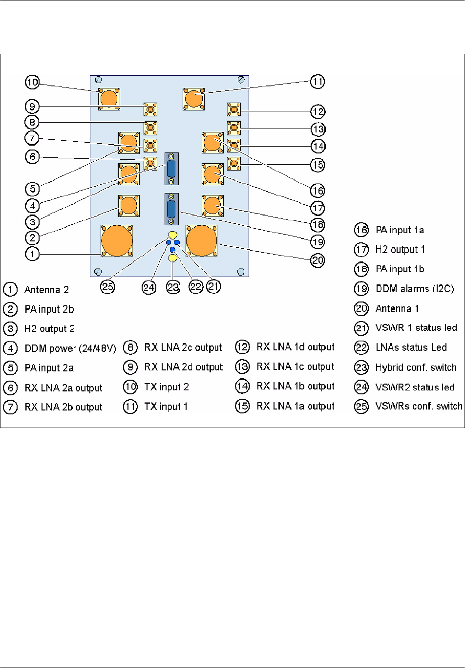
BTS18000 modules description Nortel Networks Confidential
4--44
PE/DCL/DD/0160
411--9001--160 Standard 15.104/EN June 2005 Copyright ©2002--2005 Nortel Networks
4.7.2.2 DDM H2
Figure 4--15 DDM H2 front panel

BTS18000 modules descriptionNortel Networks Confidential 4--45
BTS18000 Reference Manual
Copyright ©2002--2005 Nortel Networks
4.7.3 Physical and electrical characteristics
Module name Height
(mm)
Width
(mm)
Depth
(mm)
Weight
(Kg)
DDM / DDM H2 190.7 149.7 400 11
Table 4--28 DDM / DDM H2 dimensions and weight
Maximum number per cabinet: 6.
Maximum total power consumption:
21 W, for GSM1800 and GSM1900,
35 W, for others.
Input voltage range: 20 V -- 60 V.
Associated breaker:
Digital breaker (BTS18010),
CB3 digital/RICO/user breaker (BTS18020).
4.7.4 Interface description
The DDM provides the following interfaces:
radio interface:
•
antenna ports: two 7/16 coaxial 50 ohms connectors,
•
TX input ports: two QN type 50 ohms connectors,
•
RX outputs: eight QMA type 50 ohms connectors,
digital/power interface:
•
24/48V wide range input power feeder,
•
board presence detection and inventory I2C link to the ABM.
BTS18000 modules description Nortel Networks Confidential
4--46
PE/DCL/DD/0160
411--9001--160 Standard 15.104/EN June 2005 Copyright ©2002--2005 Nortel Networks
4.7.5 DDM specific LEDs behavior
Three LEDs are located on the DDM font panel in order to monitor DDM internal
alarm:
one LED is dedicated to LNAs,
two LEDs are dedicated to VSWR meter:
•
one for antenna 1 port,
•
one for antenna 2 port.
Table 4--29 describes the DDM specific LEDs behavior.
LED Name Color Meaning
LNA
F
ON when DDM is powered on
VSWR1
F
F
Red: Port 1 VSWR alarm level 3
Amber: Port 1 VSWR alarm level 2
OFF: no alarm or level 1
VSWR2
F
F
Red: Port 2 VSWR alarm level 3
Amber: Port 2 VSWR alarm level 2
OFF: no alarm or level 1
Table 4--29 DDM specific LEDs behavior
4.7.6 Configuration of the DDM switches for commissioning
Two four--position rotate switches are located on the DDM front panel (see
Figure 4--15).
These switches must be positioned on site:
The hybrid configuration switch (only present on DDM H2) is used to inform the
system about the use of the two 2--way hybrid (by--passed or not).
Table 4--30 gives the switch position meaning.
Hybrid configuration switch Switch position
DDM with two hybrids 0
DDM with hybrid 1 connected 1
DDM with hybrid 2 connected 2
DDM without hybrid 3
Table 4--30 DDM switches configuration

BTS18000 modules descriptionNortel Networks Confidential 4--47
BTS18000 Reference Manual
Copyright ©2002--2005 Nortel Networks
The VSWR switch (only on DDMs with VSWR option) allows modifying, on
site, the VSWR meter thresholds on both antenna ports. The three first positions
(positions 0, 1 and 2) are used to offset VSWR thresholds of respectively 0, 2 or 4
dB.
The fourth position (test position) checks that the three LEDs operate correctly.
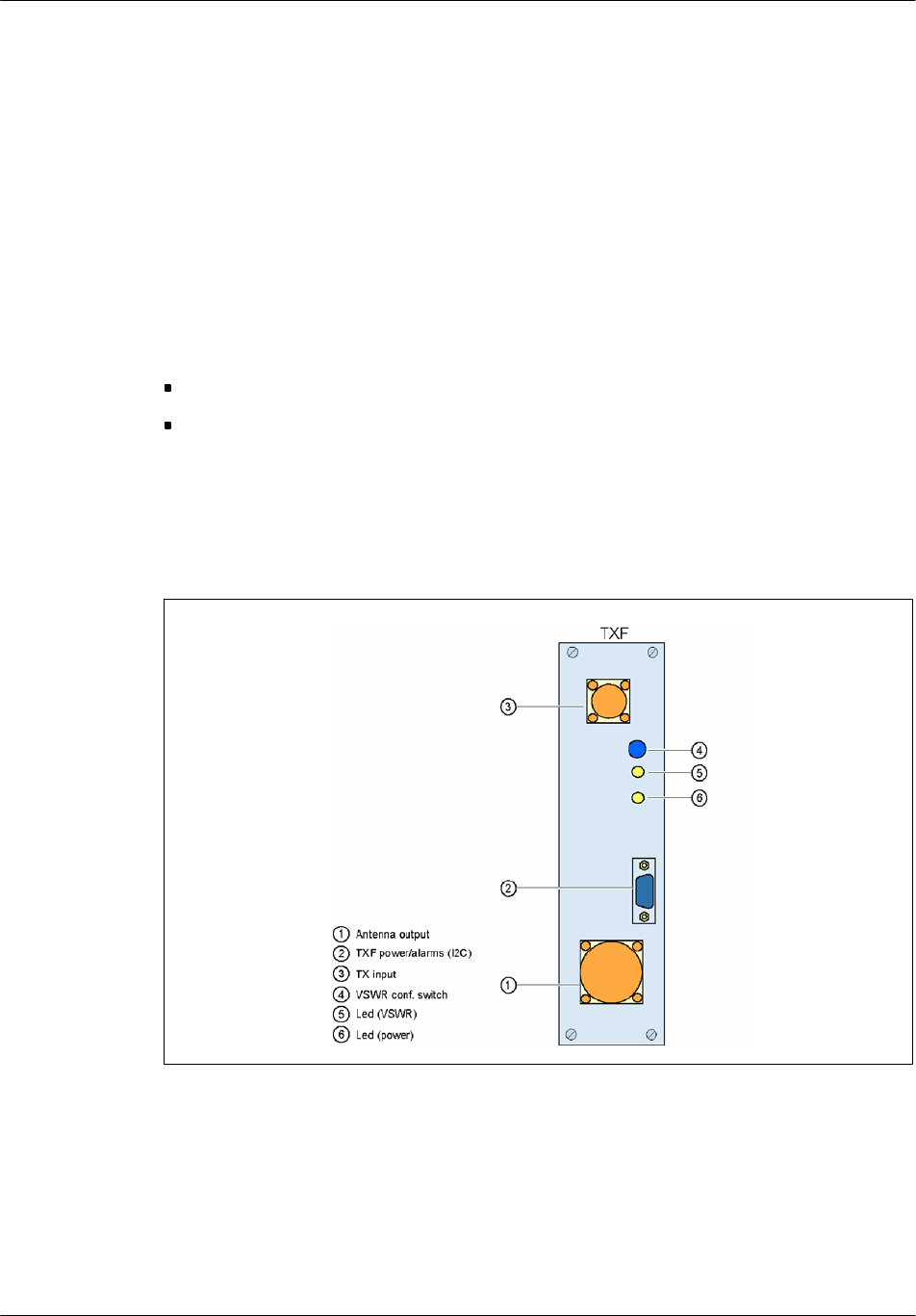
BTS18000 modules description Nortel Networks Confidential
4--48
PE/DCL/DD/0160
411--9001--160 Standard 15.104/EN June 2005 Copyright ©2002--2005 Nortel Networks
4.8 Transmit Filter (TXF)
4.8.1 Main functions
The TXF is used, as a complement of the DDM, each time extra transmit capacity
is required without need of receive capacity. It allows direct connection from the
RM PA output to the antenna.
The TXF only filters the signal transmitted from the PA to the antenna and does not
provide the reception path.
The TXF accommodates the same options as the DDM:
H2 coupling,
VSWR meter.
4.8.2 Front panel
4.8.2.1 TXF
Figure 4--16 TXF front panel
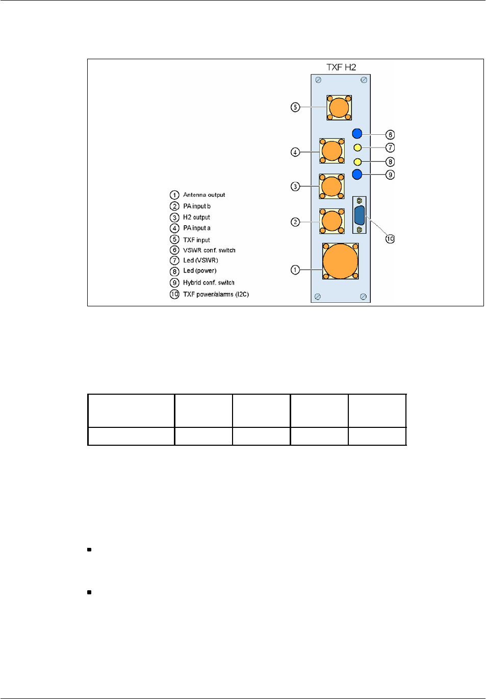
BTS18000 modules descriptionNortel Networks Confidential 4--49
BTS18000 Reference Manual
Copyright ©2002--2005 Nortel Networks
4.8.2.2 TXF H2
Figure 4--17 TXF H2 front panel
4.8.3 Physical and electrical characteristics
Module name Height
(mm)
Width
(mm)
Depth
(mm)
Weight
(Kg)
TXF / TXF H2 190.7 49.7 400 <5
Table 4--31 TXF / TXF H2 dimensions and weight
Maximum number per cabinet: 18.
Maximum power consumption:
0.6 W, on RF voltage (5 V). This power is supplied by the DDM.
Input voltage range:
4.7 V -- 5.5 V.
Associated breaker: digital breaker.
BTS18000 modules description Nortel Networks Confidential
4--50
PE/DCL/DD/0160
411--9001--160 Standard 15.104/EN June 2005 Copyright ©2002--2005 Nortel Networks
4.8.4 Interface description
The TXF provides the following interfaces:
radio interface:
•
antenna port: one 7/16 coaxial 50 ohms connector,
•
TX input port: one QN type 50 ohms connector,
digital/power interface:
•
board presence detection and inventory I2C link to the ABM.
4.8.5 TXF specific LEDs behavior
Two LEDs are located on the TXF font panel in order to monitor TXF alarm:
one LED is dedicated to DC power status,
one LED is dedicated to VSWR meter.
Table 4--32 describes the TXF specific LEDs behavior.
LED Name Color Meaning
Power
F
ON when TXF is powered on
VSWR
F
F
Red: VSWR alarm level 3
Amber: VSWR alarm level 2
OFF: no alarm or level 1
Table 4--32 TXF specific LEDs behavior
4.8.6 Configuration of the TXF switches for commissioning
Two switches are located on the TXF front panel (see Figure 4--17). These switches
must be positioned on site:
The hybrid configuration two--position switch (only present on TXF H2) is used
to inform the system about the use of the hybrid (by--passed or not).
Table 4--33 gives the switch position meaning.
Hybrid configuration switch Switch position
TXF with hybrid 0
TXF without hybrid 1
Table 4--33 TXF switches configuration

BTS18000 modules descriptionNortel Networks Confidential 4--51
BTS18000 Reference Manual
Copyright ©2002--2005 Nortel Networks
The VSWR four--position switch allows modifying, on site, the VSWR meter
thresholds on both antenna ports. The three first positions (positions 0, 1 and 2)
are used to offset VSWR thresholds of respectively 0, 2 or 4 dB.
The fourth position (test position) checks that the two LEDs operate correctly.

Dimensioning and Configuration rulesNortel Networks Confidential 10--1
BTS18000 Reference Manual
Copyright ©2002--2005 Nortel Networks
10 DIMENSIONING AND CONFIGURATION RULES
For information on dimensioning and configuration, refer to the following
engineering document: GSM/GPRS/EDGE BSS Engineering Rules
(PE/DCL/DD/0138).

Wireless Service Provider Solutions
BTS18000 Reference Manual
Copyright ©2002--2005 Nortel Networks, All Rights Reserved
NORTEL NETWORKS CONFIDENTIAL:
The information contained in this document is the property of Nortel
Networks. Except as specifically authorized in writing by Nortel
Networks, the holder of this document shall keep the information
contained herein confidential and shall protect same in whole or in part
from disclosure and dissemination to third parties and use for evaluation,
operation and maintenance purposes only.
You may not reproduce, represent, or download through any means, the
information contained herein in any way or in any form without prior
written consent of Nortel Networks.
The following are trademarks of Nortel Networks: *NORTEL
NETWORKS, the NORTEL NETWORKS corporate logo, the NORTEL
Globemark, UNIFIED NETWORKS, S2000, S4000, S8000.
GSM is a trademark of France Telecom.
All other brand and product names are trademarks or registered
trademarks of their respective holders.
Publication Reference
PE/DCL/DD/0160 411--9001--160
15.104/EN
June 2005
Originated in France
For more information, please contact:
For all countries, except USA:
Documentation Department
Parc d’activité de Magny--Chateaufort
CHATEAUFORT
78928 YVELINES CEDEX 9
FRANCE
Email : gsmntp@nortelnetworks.com
Fax : (33) (1) 39--44--50--29
In the USA:
2221 Lakeside Boulevard
Richardson TX 75082
USA
Tel: 1--800--4 NORTEL
1--800--466--7838 or (972) 684--5935
Internet Address:
http://
www.nortelnetworks.com