Avaya Canada CTR2807M LMDS CPE Transceiver User Manual 0000007 08 0292
Avaya Canada Corporation LMDS CPE Transceiver 0000007 08 0292
Contents
- 1. CTR manual
- 2. Installation Manual
- 3. CPE Installation
Installation Manual

PROPRIETARY INFORMATION: The information contained in this document
is the property of Nortel Networks. Except as specifically authorized in writing,
the holder of this document shall keep all information contained herein
confidential and shall protect same in whole or in part from disclosure and
dissemination to third parties.
BWA - Customer Premise Equipment
Installation
Installation Method – 08-0292
September 22, 2000
Issue Number: 3.1
Pkgid: 0000007
Nortel 2000
All Rights Reserved

BWA - Customer Premise Equipment Installation / 1
September 22, 2000 Method 08-0292
Table of Contents
1.0 General Information . . . . . . . . . . . . . . . . . . . . . . . . . . . . . . . . . . . . . . . . . . . . . . . . . . . . . . . 3
1.1 Description . . . . . . . . . . . . . . . . . . . . . . . . . . . . . . . . . . . . . . . . . . . . . . . . . . . . . . . . . . . . 3
1.2 Sequence . . . . . . . . . . . . . . . . . . . . . . . . . . . . . . . . . . . . . . . . . . . . . . . . . . . . . . . . . . . . . 3
1.3 Reason for Reissue . . . . . . . . . . . . . . . . . . . . . . . . . . . . . . . . . . . . . . . . . . . . . . . . . . . . . . 3
2.0 Material Requirements . . . . . . . . . . . . . . . . . . . . . . . . . . . . . . . . . . . . . . . . . . . . . . . . . . . . . 3
2.1 Required Documents . . . . . . . . . . . . . . . . . . . . . . . . . . . . . . . . . . . . . . . . . . . . . . . . . . . . 3
2.2 Tools . . . . . . . . . . . . . . . . . . . . . . . . . . . . . . . . . . . . . . . . . . . . . . . . . . . . . . . . . . . . . . . . . 4
2.3 Supplies . . . . . . . . . . . . . . . . . . . . . . . . . . . . . . . . . . . . . . . . . . . . . . . . . . . . . . . . . . . . . . 4
2.4 Customer Supplied Equipment . . . . . . . . . . . . . . . . . . . . . . . . . . . . . . . . . . . . . . . . . . . . . 4
2.5 Emergency Contacts . . . . . . . . . . . . . . . . . . . . . . . . . . . . . . . . . . . . . . . . . . . . . . . . . . . . . 4
3.0 Precautions and Preparations . . . . . . . . . . . . . . . . . . . . . . . . . . . . . . . . . . . . . . . . . . . . . . . 5
3.1 Precautions . . . . . . . . . . . . . . . . . . . . . . . . . . . . . . . . . . . . . . . . . . . . . . . . . . . . . . . . . . . . 5
3.2 Preparations . . . . . . . . . . . . . . . . . . . . . . . . . . . . . . . . . . . . . . . . . . . . . . . . . . . . . . . . . . . 5
4.0 Procedure . . . . . . . . . . . . . . . . . . . . . . . . . . . . . . . . . . . . . . . . . . . . . . . . . . . . . . . . . . . . . . . . 6
4.1 Overview . . . . . . . . . . . . . . . . . . . . . . . . . . . . . . . . . . . . . . . . . . . . . . . . . . . . . . . . . . . . . . 6
4.2 CPE Cabinet Installation . . . . . . . . . . . . . . . . . . . . . . . . . . . . . . . . . . . . . . . . . . . . . . . . . . 6
Procedure 1 – CPE Cabinet Installation . . . . . . . . . . . . . . . . . . . . . . . . . . . . . . . . . . . . . . 7
4.3 NIU Installation . . . . . . . . . . . . . . . . . . . . . . . . . . . . . . . . . . . . . . . . . . . . . . . . . . . . . . . . 12
Procedure 2 – NIU Installation . . . . . . . . . . . . . . . . . . . . . . . . . . . . . . . . . . . . . . . . . . . . 12
4.4 Backup Battery Installation . . . . . . . . . . . . . . . . . . . . . . . . . . . . . . . . . . . . . . . . . . . . . . . 14
Procedure 3 – Backup Battery Installation . . . . . . . . . . . . . . . . . . . . . . . . . . . . . . . . . . . 14
4.5 CTR Installation PLUMB Mount . . . . . . . . . . . . . . . . . . . . . . . . . . . . . . . . . . . . . . . . . . . 16
Procedure 4 – CTR Installation Plumb Mount . . . . . . . . . . . . . . . . . . . . . . . . . . . . . . . . 17
4.6 CTR Installation Fine Adjust Mount . . . . . . . . . . . . . . . . . . . . . . . . . . . . . . . . . . . . . . . . . 21
Procedure 5 – CTR Installation Fine Adjust Mount . . . . . . . . . . . . . . . . . . . . . . . . . . . . . 22
5.0 References . . . . . . . . . . . . . . . . . . . . . . . . . . . . . . . . . . . . . . . . . . . . . . . . . . . . . . . . . . . . . . 25
6.0 Appendices . . . . . . . . . . . . . . . . . . . . . . . . . . . . . . . . . . . . . . . . . . . . . . . . . . . . . . . . . . . . . 26
Appendix A – Acronyms . . . . . . . . . . . . . . . . . . . . . . . . . . . . . . . . . . . . . . . . . . . . . . . . . . . . 26
Last Page. . . . . . . . . . . . . . . . . . . . . . . . . . . . . . . . . . . . . . . . . . . . . . . . . . . . . . . . . . . . . . . . 26

2 / BWA - Customer Premise Equipment Installation
Method 08-0292 September 22, 2000
Illustrations
Figure 1 – Tools . . . . . . . . . . . . . . . . . . . . . . . . . . . . . . . . . . . . . . . . . . . . . . . . . . . . . . . . . . . .4
Figure 2 – CPE Zone 2 Anchor . . . . . . . . . . . . . . . . . . . . . . . . . . . . . . . . . . . . . . . . . . . . . . .11
Figure 3 – CPE Zone 4 Anchor . . . . . . . . . . . . . . . . . . . . . . . . . . . . . . . . . . . . . . . . . . . . . . .11
Figure 4 – NIU dc Terminal Strip . . . . . . . . . . . . . . . . . . . . . . . . . . . . . . . . . . . . . . . . . . . . .14
Figure 5 – Backup Battery Layout . . . . . . . . . . . . . . . . . . . . . . . . . . . . . . . . . . . . . . . . . . . . .16
Figure 6 – Plumb CTR . . . . . . . . . . . . . . . . . . . . . . . . . . . . . . . . . . . . . . . . . . . . . . . . . . . . . .21
Figure 7 – Fine Adjust Mount . . . . . . . . . . . . . . . . . . . . . . . . . . . . . . . . . . . . . . . . . . . . . . . .25

BWA - Customer Premise Equipment Installation / 3
September 22, 2000 Method 08-0292
1.0 General Information
1.1 Description
Purpose: This method covers the procedures required for the
installation of the Reunion Customer Premise Equipment (CPE).
Equipment: The CPE contains an indoor unit, the Network Interface
Unit (NIU), and an outdoor unit, the Customer Transceiver (CTR). The
NIU provides E1/T1 and 10 Base T interfaces to the Reunion System.
The CTR provides the up and down conversion of IF and RF signals for
the CPE site.
Application: This method is intended for initial installations and
extension installations.
Service Impact: None.
1.2 Sequence
This is a stand-alone method.
1.3 Reason for Reissue
This method was edited and renewed. Method 08-0282, "CTR 2400
Installation" and Method 08-6002, "MMIC CTR Installation" were
combined into this method (August 2000).
This is the initial release of this method.
2.0 Material Requirements
2.1 Required Documents
Installation Safety Manual (ISM) - can be located on the web at URL
aralia/usa/safety/safety.html.
•Job Start Information Package (JSIP)
•Engineering Package

4 / BWA - Customer Premise Equipment Installation
Method 08-0292 September 22, 2000
2.2 Tools
The tools listed in Figure 1 are required to perform this method.
2.3 Supplies
•Electrical Tape
•Cable Labels
•Tie Wraps 20"
•Lineman’s Bag
•Safety Strap Harness with Ring
•50’ Rope
•Masking Tape
•Dust mask (if required)
2.4 Customer Supplied Equipment
•Cabinet Ground Cable
•Cabinet Power Connection
•Secured Antenna Mast
2.5 Emergency Contacts
For U.S. Wireless Market:
•Nortel Emergency Technical Assistance Service (ETAS)
972-BWA-ETAS (972-292-3827).
•Nortel Technical Assistance Center (TAC) - US
972-292-3827 (#3).
No other materials are required to perform this method.
Figure 1 – Tools
Tools Description
K003041 Field Technician Tool Kit
K003069 Seismic Kit

BWA - Customer Premise Equipment Installation / 5
September 22, 2000 Method 08-0292
3.0 Precautions and Preparations
3.1 Precautions
Observe the general safety precautions against personal injury and
equipment damage outlined in the ISM at all times.
Read this method completely prior to attempting to handle or install the
CPE.
Any on site problems, non-compliances with work orders, or potential
hazards should be reported immediately to the Program Manager.
Use caution when climbing on, around, or near equipment. Be aware of
trip hazards as you walk or climb around the work environment.
When working on high buildings, take extra care to ensure that no
debris, tools, or equipment are allowed to blow off or fall from the
working area.
All company tools, test equipment, etc. are to be kept with the engineer
responsible at all times, except when securely locked in equipment
rooms or transportation vehicle.
Locate the main power shut-off switch controlling the equipment being
worked on. This is important in the event of an accident so that power
can quickly be cut.
3.2 Preparations
Prior to starting the operations presented in this method, arrange all
materials, tools, and test equipment at the work location to minimize
fatigue and inconvenience.
Prior to the installation of any equipment, inventory all materials by
using the bill of materials (BOM).
Check each package for any sign of physical damage. If damage is
visible, immediately report to the Program Manager.
Check all contents against the order forms and packing slips to ensure
that all components are received. Make notes of any missing parts or
equipment, and notify the next level of support with any deficiencies.
Know exactly where to place the equipment before removing it from the
package.
6 / BWA - Customer Premise Equipment Installation
Method 08-0292 September 22, 2000
4.0 Procedure
4.1 Overview
This method covers the procedures to install the CPE cabinet, Backup
Batteries, NIU, and CTR. The NIU provides the interface for E1/T1 and
10 Base T to the Reunion System. The NIU modulates these signals into
a Quadrature Amplitude Modulation (QAM) signal onto an
Intermediate Frequency (IF) carrier and sends it to the CTR. The CTR
then up converts and amplifies the IF into Radio Frequency (RF) in the
microwave range, sending it to the Network Node Equipment (NNE)
Basestation Transceiver (BTR). Upon receiving the RF from the BTR,
the CTR down converts and amplifies it to IF, sending it to the NIU. The
NIU then demodulates the IF and QAM into the E1/T1 and 10 Base T
signals.
4.2 CPE Cabinet Installation
The following procedure covers the mounting of the CPE cabinet.
Using the Engineering Package, determine which type of cabinet is to be
installed. The cabinet is provided with floor mounting brackets and an
anchor kit (NTN523CC or NTN523CD). The mounting of the brackets
is optional. (Check with Program Management for instructions on this
issue.)
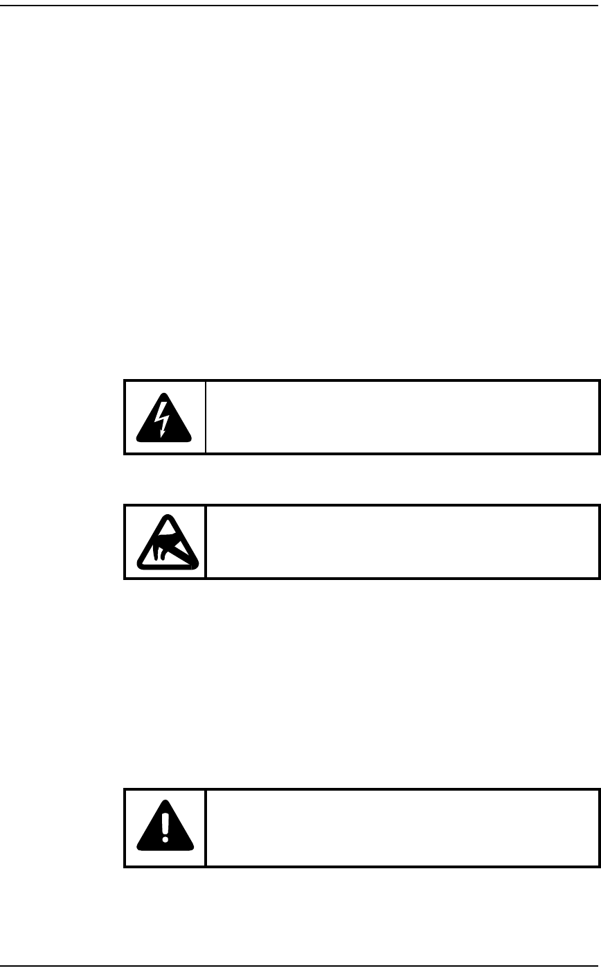
SHOCK:
Disconnect all power when working on power supplies.
Caution:
Be aware of electrostatic sensitive devices (ESD)
requirements when handling BWA equipment.
Danger:
The cabinet weighs from 625 lbs to 905 lbs (284 kg to 411 kg).
Use at least three people to move the cabinet. Wear
protective footwear and gloves.

BWA - Customer Premise Equipment Installation / 7
September 22, 2000 Method 08-0292
Procedure 1 – CPE Cabinet Installation (Page 1 of 4)
Step Action Observation
1Remove any packaging from around the cabinet.
2Remove the bolts securing the bottom of the
cabinet to the wooden pallet.
Note: Do not throw away any of the steel
mounting brackets securing the cabinet to the
pallet. These bars are used to install the Seismic
cabinet.
Cabinet is now on rollers.
3Check the interior of the cabinet for loose parts
inside (small parts, bags, and boxes).
4Set these parts aside. Do not throw them away.
5Have the Program Manager coordinate with local
customer representatives to discard the cabinet
packing materials.
6Check for any obvious physical signs of damage
to the cabinet. Any defects should be reported to
the Program Manager before proceeding.
Dented or damaged panels, plates, screws,
bolts, braces and supports.
7Work with the customer representative to
determine the proper location for the CPE
cabinet in the equipment room.
CPE Cabinet placement conforms to the
customer’s site location plans. Notify the
Program Manager if there are environmental
hazards that could cause equipment damage
(wind, water, falling objects and/or rodents or
insects).
8Confirm beforehand that the CPE cabinet doors
will have adequate space to fully open. This is
especially important prior to drilling or bolting
the cabinet to the floor.
9When not bolting the cabinet to the floor, use an
adjustable wrench and unscrew the leveling feet
on the bottom of the cabinet. Place a level on the
cabinet to ensure it is level, and adjust the feet
until cabinet is level. If the cabinet is to bolted to
the floor, proceed to the next step.

8 / BWA - Customer Premise Equipment Installation
Method 08-0292 September 22, 2000
10 The following steps will cover bolting the
cabinet to the floor in a Zone 2 or Zone 4
application.
Note: The minimum thickness of the concrete
floor is 6.3" (160mm) for a Seismic cabinet
(Zone 2), and 7.5" (190mm) for Seismic cabinet
(Zone 4).
11 Re-install the two heavy steel mounting brackets
at the front and rear of the cabinet.
12 Mark the front base reference line and the end
base reference line on the floor using the tape
measure, square, straight edge, and felt tip pin.
13 Mark the location of the six anchor holes with a
felt tip pin.
14 Move the cabinet away from its intended
position.
15 Punch the centers of the hole markings using the
hammer and center punch.
Note: With a star tipped drill bit, a center hole is
not required.
16 For mounting the Seismic cabinet (Zone
2)(NTN523CC anchor kit), drill the anchor holes
to the depth of 4.33" (110mm) using an 18mm
drill bit.
Note: For ease, mark the drill bit with masking
tape for the depth.
17 For mounting the Seismic cabinet (Zone
4)(NTN523CD anchor kit), go to step 24.
18 Blow the debris from the hole and clean the area
with the vacuum cleaner. Ensure the hole is free
of debris.
19 Roll the cabinet back into place, centering over
the six holes.
Procedure 1 – CPE Cabinet Installation (Page 2 of 4)
Step Action Observation

BWA - Customer Premise Equipment Installation / 9
September 22, 2000 Method 08-0292
20 Place the isolator pad between the floor and
cabinet mounting plates.
Note: If spacing between the floor and mounts is
too tight, lower the leveling feet to increase the
space.
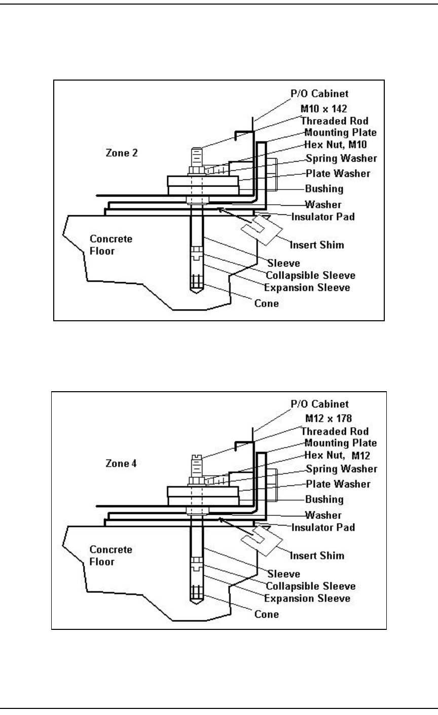
21 For Seismic (Zone 2)(NTN523CC anchor kit),
use a hammer and tap the pre-assembled anchor
with washers into the hole. Refer to Figure 2.
Note: Do not expand the anchor by hand before
tapping it into the hole. The top surface of the
sleeve (bottom of washers) must be flush with
the floor surface.
22 Tighten the nut a little to seat the anchor firmly
against the hole.
23 Use a level and check the cabinet level. Insert
shims either between the mounting plate and
insulator pad, or between the insulator pad and
floor to level the cabinet. Tighten the nut on the
anchors with a torque of 40 ft-lbs. Ensure the
cabinet is still level and insert shims as needed to
level the cabinet.
24 For mounting the Seismic cabinet (Zone
4)(NTN523CD anchor kit), drill the anchor holes
to a depth of 4.92" (125mm) using a 22mm drill
bit.
Note: For ease, mark the drill bit with masking
tape for the depth.
25 Blow the debris from the hole and clean the area
with the vacuum cleaner. Ensure the hole is free
of debris.
26 For Seismic (Zone 4)(NTN523CD anchor kit),
insert the adhesive capsules completely into the
holes.
Note: Adhesive capsules are longer than the
standard embedment and can protrude from the
floor.
Procedure 1 – CPE Cabinet Installation (Page 3 of 4)
Step Action Observation

10 / BWA - Customer Premise Equipment Installation
Method 08-0292 September 22, 2000
27 Insert the square drive shaft into the
recommended drill and attach the proper impact
socket. The Hilti hammer drill must be set on
rotary hammer, not rotation only.
28 Put the anchor in front of the hole. Allow the
anchor to be driven until the top surface of the
setting tool is flush with the floor surface.
Do not press excessively hard on the anchor.
Once the anchor is properly embedded, switch
off the drill immediately to prevent excessive
adhesive from spilling out of the hole.
29 Let the adhesive cure. Follow this table for cure
time.
Floor Temp Curing Time
40 C 20 min
20 C 20 min
10 C 30 min
0 C 1 hr
-5 C 5 hr
-15 C 24 hr
Note: The multi meter can be used to take the
temperature of the floor.
30 Install the mounting brackets, insulator pad,
cabinet, insulator washers, and bolts in the
sequence shown in Figure 3.
31 Use a level and check the cabinet level. Insert
shims either between the mounting plate and
insulator pad, or between the insulator pad and
floor to level the cabinet. Using an allen key and
a torque wrench, tighten the anchors to 29.4
ft-lbs. Ensure the cabinet is still level and insert
shims as needed to level the cabinet.
32 End of Procedure.
Procedure 1 – CPE Cabinet Installation (Page 4 of 4)
Step Action Observation
BWA - Customer Premise Equipment Installation / 11
September 22, 2000 Method 08-0292
Figure 2 – CPE Zone 2 Anchor
Figure 3 – CPE Zone 4 Anchor

12 / BWA - Customer Premise Equipment Installation
Method 08-0292 September 22, 2000
4.3 NIU Installation
The following procedure covers the installation of the NIU into the CPE
cabinet. The NIU is typically installed into a 23" cabinet. However, it
is flexible enough to not be installed in this manner. The installation
may vary from site to site, and if there are concerns about the site (i.e.
environmental, water, grounding etc.), contact the Program Manager.
Procedure 2 – NIU Installation (Page 1 of 2)
Step Action Observation
1The NIU installation may take place in a cabinet
already in use for customer traffic via wireline.
If the cabinet already has power applied to it,
verify with the local customer the cabinet status.
Verify the fuse and circuit breaker layout of the
cabinet with local customer to eliminate service
outages.
2If the cabinet is not inservice, ensure all fuses are
removed and circuit breakers in the Helios, ac
circuit breaker panel, and the dc battery shutoff
switch are turned OFF.
Note: If the cabinet is inservice and cannot be
powered down, verify with the local customer
the fuse layout to ensure proper fusing of the
NIU. Typically, fuse #2 is for NIU#1, and fuse
#8 is for NIU #2. Verify with the local customer
that these fuses remain for the NIU(s) and
remove them.
The cabinet has no power applied to it.
3Remove the NIU from its box and inspect it for
damage. Do not install damaged equipment.
Using a #2 phillips screwdriver, remove the four
screws on the sides of the NIU. There are two
screws on each side at the front of the NIU that
will need to be removed for the NIU to fit into
the NIU mounting bracket.
The four screws are now removed.
4Place the NIU into the shelf centered in the
cabinet. Make sure the NIU is secured and the
side vent holes match the vents in the NIU
mounting bracket. The NIU connections will be
at the back of the cabinet.
NIU is now inserted into the mounting bracket.
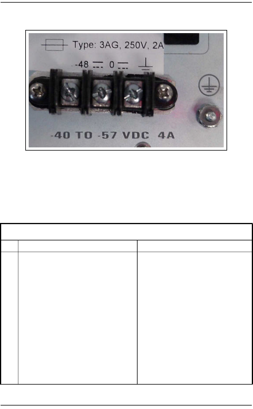
5On the back of the NIU, remove the left (-48V)
and center (0V) terminal screws from the dc
terminal block.
The terminal screws are now removed.
Refer to Figure 4.

BWA - Customer Premise Equipment Installation / 13
September 22, 2000 Method 08-0292
6Locate the NIU power wires in the cabinet.
Note: There will be a pair of wires for each NIU
shelf. Each wire will be insulated.
Note: Depending on the model of NIU being
installed, it may be utilizing an ac power cord.
Locate the ac power cord and connect to NIU
as required. If the NIU is an ac model, go to
step 8.
7Carefully remove the insulation from one pair of
wires. Verify with a multi meter that no dc is
present on the wires.
8Locate and connect the white wire with a green
strip (ground wire) to the ground post on the
lower right hand corner on the back of the NIU.
Be careful not to strip the bolt when putting the
nut on.
Note: There will be a ground wire for each NIU
shelf.
Refer to Figure 4 for an illustration of the
ground post.
9Connect the white wire with the red stripe to the
left terminal labeled -48 V on the back of the
NIU.
Note: If the NIU is an ac model, go to step 11.
Refer to Figure 4 for an illustration of the dc
terminal.
10 Connect the white wire with no stripe to the
center terminal labeled 0 V on the back of the
NIU.
Refer to Figure 4 for an illustration of the dc
terminal.
11 End of Procedure. NIU power up will be in
Method 22-0295.
Procedure 2 – NIU Installation (Page 2 of 2)
Step Action Observation
14 / BWA - Customer Premise Equipment Installation
Method 08-0292 September 22, 2000
Figure 4 – NIU dc Terminal Strip
4.4 Backup Battery Installation
The following procedure covers the installation of the backup batteries
inside the CPE cabinet and their cabling.
Procedure 3 – Backup Battery Installation (Page 1 of 2)
Step Action Observation
1Unpack and inspect the batteries for any damage.
Do not install damaged equipment.
2Verify that the Battery Switch at the lower left
corner of the cabinet is OFF (viewed from the
front).
3Loosen the captive screws on each side of the bar
across the front of the battery tray and remove
the bar.
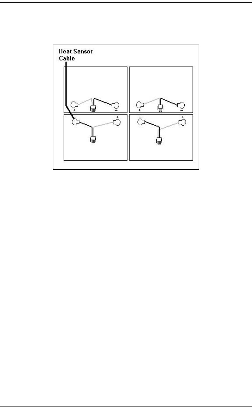
4Locate the wire harnesses for the battery cabling.
Attach the harness labeled LR to the battery
going in the Left Rear position.
5Attach the harness labeled RR to the battery
going in the Right Rear position.
6Attach the harness labeled RF to the battery
going in the Front Right position.

BWA - Customer Premise Equipment Installation / 15
September 22, 2000 Method 08-0292
7Attach the harness labeled LF to the battery
going in the Front Left position.
8Attach the harness cables together with the I/O
cable. Measure the voltage on the I/O cable
using a multi meter. The measured voltage
should be around -51 V dc, depending on battery
charge state.
9Place the batteries so they can be put into the
battery tray without disconnecting the cables.
Slide the two rear batteries into the tray, and
place the front right battery into the tray.
Note: The battery terminals will be toward the
middle of the tray. Refer to Figure 5.
10 Before placing the front left battery into the tray,
the heat sensor cable needs to be secured under
the negative terminal. Place the front left battery
into the tray once the heat sensor cable is secure.
11 Route the I/O cable so that it can be connected to
the male connector at the back of the Battery
Switch box. Connect the I/O cable to the male
connector at the switch box. The female
connector at the switch box will be connected to
the battery cable coming from the rectifier
(Helios).
12 Install the bar across the front of the battery tray
and secure with the two captive screws.
13 End of procedure.
Procedure 3 – Backup Battery Installation (Page 2 of 2)
Step Action Observation
16 / BWA - Customer Premise Equipment Installation
Method 08-0292 September 22, 2000
Figure 5 – Backup Battery Layout
4.5 CTR Installation PLUMB Mount
The following procedure covers the installation of the CTR with the
PLUMB Mount. This mount can only be utilized with the PLUMB
CTR. If the site uses an MMIC CTR, a Fine Adjust Mount will be used.
For an MMIC or PLUMB CTR using the Fine Adjust Mount, go to
subsection 4.4 "CTR Installation Fine Adjust Mount."
BWA - Customer Premise Equipment Installation / 17
September 22, 2000 Method 08-0292
Procedure 4 – CTR Installation Plumb Mount (Page 1 of 4)
Step Action Observation
1Unpack the CTR and Mount and inspect for
damage. Do not install damaged equipment. For
ease of installation, the CTR and mount should
be assembled on stable ground instead of on the
mast.
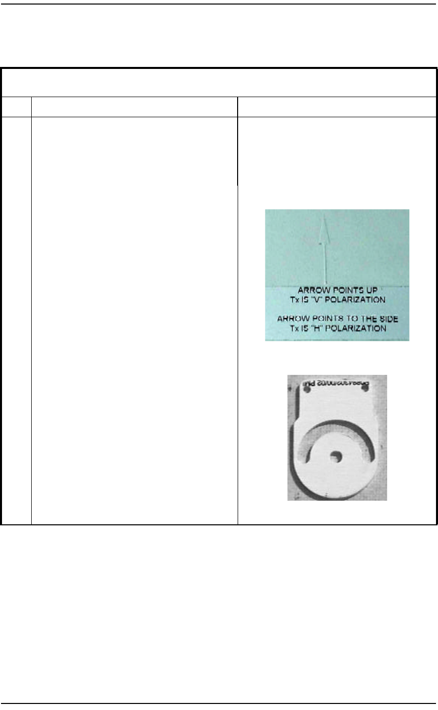
2Verify the CTR TX polarity in the Engineering
Package before installing the brackets to the
CTR.
Note: For Horizontal TX Polarity, look at the
back of the CTR antenna. Place the arrow
pointing to the right.
Note: For Vertical TX Polarity, look at the back
of the CTR antenna. Place the arrow pointing up.
PLUMB Polarization Label
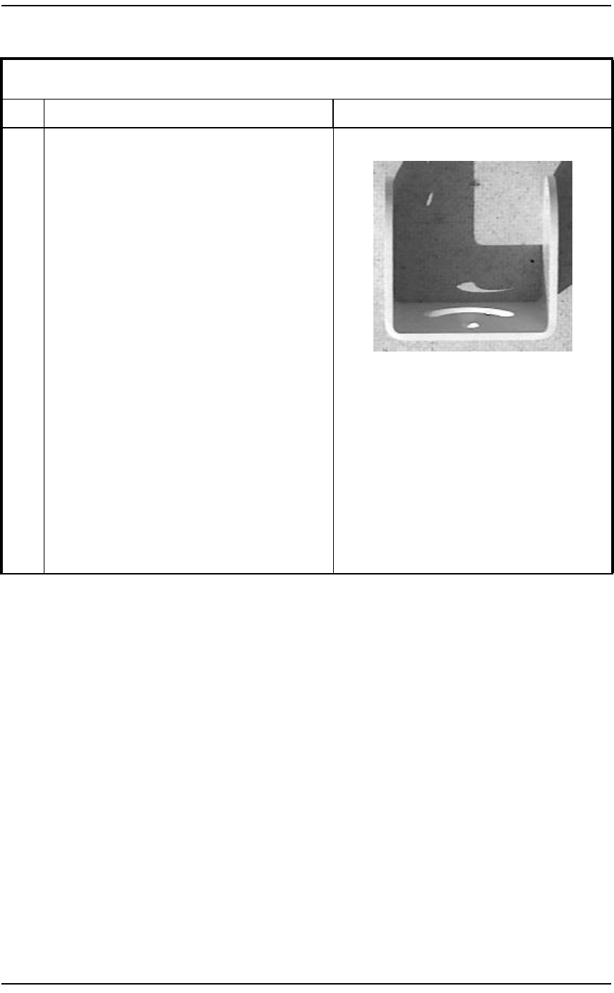
3Use a 3/8" wrench and socket/ratchet to attach
one Flat Tilt Bracket to one side of the CTR
Chassis Bracket so the polarity is correct.
Slide the two bolts in from the outside, through
the Flat Tilt Bracket holes, and through the CTR
Chassis Bracket. Place a washer and nut on each
bolt, and tighten until firmly secured to the CTR
Chassis Bracket.
Note: There are two Flat Tilt Brackets. Repeat
this step for the other flat tilt bracket to the
opposite side of the CTR chassis bracket.
Flat Tilt Bracket
18 / BWA - Customer Premise Equipment Installation
Method 08-0292 September 22, 2000
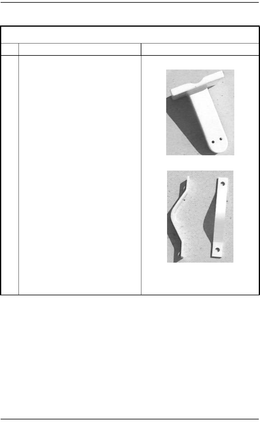
4Use a 9/16" wrench and socket/ratchet to attach
the U-Bracket to both of the Flat Tilt Brackets.
Slide the U-Bracket between the two Flat Tilt
Brackets. Insert each of the four bolts in from
the outside and through the Flat Tilt Bracket
holes. Place a washer and nut on each bolt until
tight.
Note: The nuts will only need to be snug until
antenna alignment.
U-Bracket
5Once the mounting brackets are on the CTR,
move to the antenna mast to mount the Arm
bracket (Base). This will make it easier to install
the CTR to the mast.
6Verify the Antenna Mast (pole) is secured before
installation of the CTR begins.
Note: It is the customer’s responsibility to
ensure the roof and antenna mast are structurally
adequate to meet all local, state, and federal
codes under maximum wind loading conditions.
Procedure 4 – CTR Installation Plumb Mount (Page 2 of 4)
Step Action Observation
BWA - Customer Premise Equipment Installation / 19
September 22, 2000 Method 08-0292
7Use a wrench and socket/ratchet to attach the
Pole brackets to the Arm Bracket.
Place the pole bracket on the backside of the
antenna mast and the arm bracket on the other.
Insert each of the four bolts through the pole
bracket holes into the arm bracket holes. Place a
washer and nut on each end of the bolts.
Note: Using a wrench or socket/ratchet, tighten
each nut firmly so the Arm Bracket assembly is
secured to the Antenna Mast.
Arm Bracket
Pole Brackets
8Use adequate support to prevent personal injury
or damage to equipment. Two technicians are
required for the following step.
Procedure 4 – CTR Installation Plumb Mount (Page 3 of 4)
Step Action Observation
20 / BWA - Customer Premise Equipment Installation
Method 08-0292 September 22, 2000
9Once the Arm bracket (Base) is secured to the
antenna mast, place the CTR on top of the Base
and point the CTR in the general direction of the
BTR(s). See the Engineering Package for
azimuth information.
With one technician holding the CTR, use a 9/
16" wrench and socket/ratchet to attach the CTR
to the Arm bracket (base).
Slide the two bolts in from the top side, through
the U-Bracket holes, and through the Arm
bracket (base). Place a washer and nut on each
bolt and tighten it so the CTR is secured but not
overly tight.
10 The CTR alignment is completed in Method 22-
0295. The CTR will be secured after the
alignment.
11 End of Procedure.
Procedure 4 – CTR Installation Plumb Mount (Page 4 of 4)
Step Action Observation
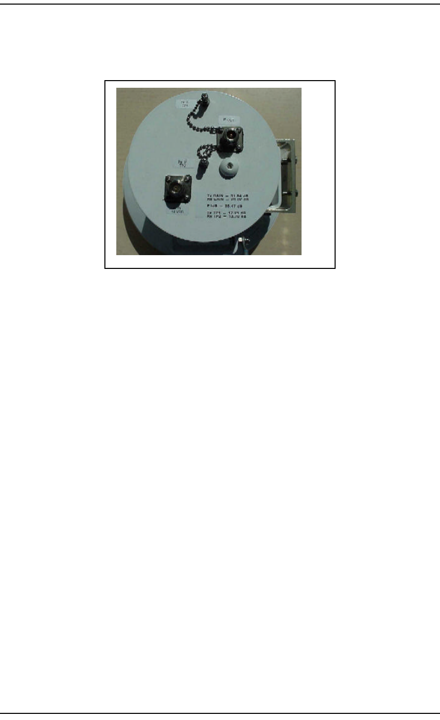
BWA - Customer Premise Equipment Installation / 21
September 22, 2000 Method 08-0292
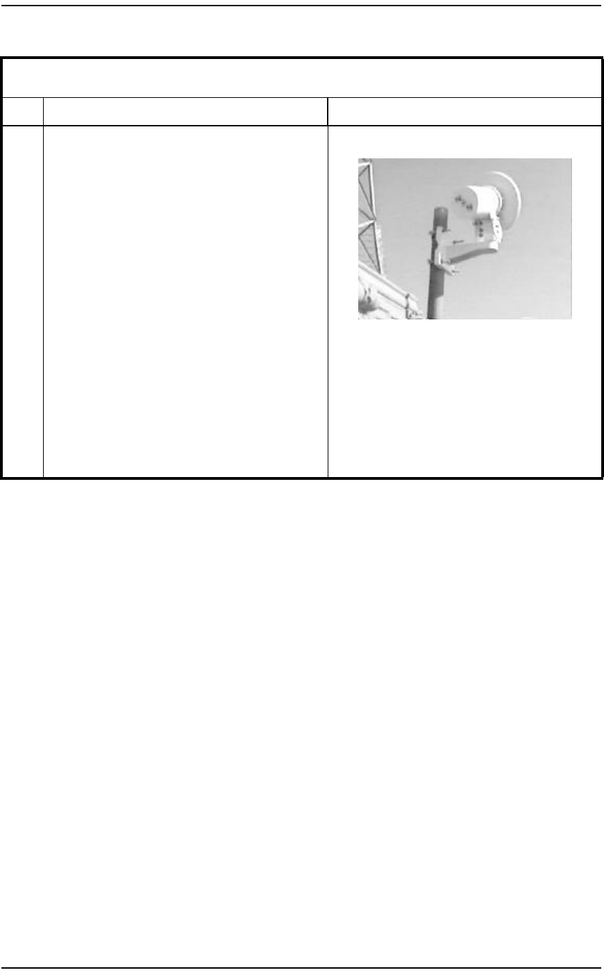
Figure 6 – Plumb CTR
4.6 CTR Installation Fine Adjust Mount
The following procedure covers the CTR Installation with the Fine
Adjust Mount. This mount can be used with the PLUMB or MMIC
CTR. To use the PLUMB CTR with this mount, an extra bracket (CPC#
A0800471) must be attached to the CTR to allow it to bolt to the mount.
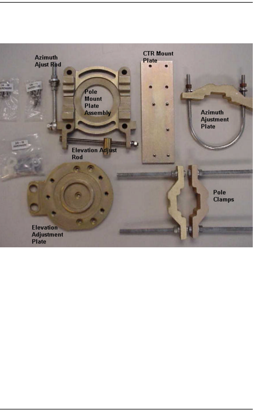
Refer to Figure 7, "Fine Adjust Mount" for a view of the mount parts.

22 / BWA - Customer Premise Equipment Installation
Method 08-0292 September 22, 2000
Procedure 5 – CTR Installation Fine Adjust Mount (Page 1 of 3)
Step Action Observation
1Unpack the CTR and Mount and inspect for
damage. Do not install damaged equipment. For
ease of installation, the CTR and mount should
be assembled on stable ground instead of on the
mast.
Note: The MMIC CTR will have a protective
cover for the radome. Do not touch the front of
the radome; the oils from the skin can cause
damage.
2Install the Azimuth adjustment plate to the
antenna mast on the opposite side of the mast the
CTR will be installed on. Using the U-bolt, split
lock washer, flat washer and bronze nut, fully
tighten the azimuth adjustment plate securely to
the pole (15 ft-lb torque).
Parts: U bolt bracket, (2) 3/8 x 16 bronze nuts,
flat washers, split lock washers.
3Install the Pole mount plate assembly to the
antenna mast so that it sits opposite the Azimuth
adjustment plate assembly. Tighten the (2) pole
clamp bars using the (4) 6.0" hex bolts, split lock
washers, flat washers, and hex nuts. The
elevation adjustment plate should fit snug to the
pole.
Note: The azimuth adjust rod is pre-assembled
when shipped from the factory. Remove the hex
nut, split lock washer, and flat washer. Slip the
rod into the slot of the azimuth adjustment plate.
Replace the hex nut, split lock washer, and flat
washer.
Parts: (4) 3/8 - 16 x 6.0" hex nut, 3/8 split lock
washer, 3/8 flat washers.
BWA - Customer Premise Equipment Installation / 23
September 22, 2000 Method 08-0292
4Attach the CTR mounting plate to the elevation
adjustment plate using (5) pan head screws and
stainless steel split lock washers. With the
proper torque (50 in-lb), fully tighten the
mounting plate to the elevation adjustment plate.
Parts: (5) 1/4-20 x 3/8 pan head screws and
stainless steel split lock washers.
Attach the mounting plate to the CTR housing
using (4) pan head screws and stainless steel split
lock washers. Fully tighten using the proper
torque (50 in-lb).
Parts: (4) 1/4-28 x 3/4 pan head screws and
stainless steel split lock washers.
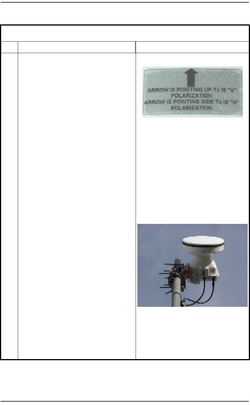
Note: Verify the CTR TX polarization with the
Engineering Package. If the TX polarization is
horizontal, the arrow will point to the right
(looking at CTR from the rear). If the TX
polarization is vertical, the arrow will point up.
MMIC Polarization Label
5Elevation adjustment assembly to pole mount
assembly. Align the large diameter hub on the
elevation adjustment plate to the pole mount
plate, inserting the brass rod into the desired
elevation adjustment hole.
In order to adjust the elevation of the antenna for
maximum uptilt angle, position the round brass
rod in the top hole of the elevation plate.
In order to adjust the elevation of the antenna for
maximum downtilt angle, position the round
brass rod in the bottom hole of the elevation
plate.
Tighten the (2) 3/8 hex bolts, split lock washers,
flat washers, and nylon washers until the antenna
is snug to the adjustment plate. Do not fully
tighten at this time.
Parts: (4) hex bolts, split lock washers, flat
washers, nylon washers.
Procedure 5 – CTR Installation Fine Adjust Mount (Page 2 of 3)
Step Action Observation

24 / BWA - Customer Premise Equipment Installation
Method 08-0292 September 22, 2000
6Fine Azimuth adjustment instructions:
Clockwise: Adjust the azimuth rod by loosing
the 3/8 hex nuts on the inside of the rod. The
antenna will move clockwise around the pole by
tightening the outer 3/8 hex nut. This can be
done until the antenna is in the desired position.
When this position is reached, fully tighten the
inside hex nuts using the proper torque (15 ft-lb).
Counter Clockwise: Adjust the azimuth rod by
loosing the 3/8 hex nut on the outside of the
adjustment rod, leaving no less than three threads
from the end. The antenna will move in a
counter clockwise movement around the pole by
tightening the inside 3/8 hex nut until the antenna
is in the desired position. When this position is
reached, fully tighten the outside hex nuts using
the proper torque (15 ft-lb).
Note: The fine azimuth adjustment allows for +/
- 10 degrees.
7Fine elevation adjustment instructions:
Uptilt adjustment: Rotate the elevation adjust
rod counter clockwise to the desired position.
Note: At this time, the (4) 3/8-16 hex bolts on
the elevation adjustment plate will be fully
tightened using the proper torque (15 ft-lb).
Downtilt adjustment: Rotate the elevation adjust
rod counter clockwise to the desired position.
Note: At this time, the (4) 3/8-16 hex bolts on
the elevation adjustment plate will be fully
tightened using the proper torque (15 ft-lb).
Note: The fine elevation adjustment allows for
+/- 25 degrees.
8Before leaving the installation, check that all
hardware on the mount and antenna are fully
tightened.
Inspection of the antenna should be performed at
least once a year to check its condition and to
ensure safe operation and maintenance.
Note: Ensure the MMIC CTR protective radome
cover is removed.
9End of Procedure.
Procedure 5 – CTR Installation Fine Adjust Mount (Page 3 of 3)
Step Action Observation
BWA - Customer Premise Equipment Installation / 25
September 22, 2000 Method 08-0292
Figure 7 – Fine Adjust Mount
5.0 References
Document Number Title
Method 08-0282 "CTR 2400 Microwave Transceiver
Installation"
Method 08-6002 "CTR MMIC Radio Installation"
Method 22-0295 "CPE Preparation and Power Up"
Method P0915936 "TAS-PTM Radio Enclosure"

26 / BWA - Customer Premise Equipment Installation
Method 08-0292 September 22, 2000
6.0 Appendices
Appendix A – Acronyms
Last Page
BTR Base Station Transceiver
CPE Customer Premise Equipment
CTR Customer Transceiver
ESD Electrostatic Sensitive Device
ETAS Emergency Technical Assistance Services
IF Intermediate Frequency
ISM Installation Safety Manual
JSIP Job Start Information Package
NIU Network Interface Unit
NNE Network Node Equipment
QAM Quadrature Amplitude Modulation
RF Radio Frequency
TAC Technical Assistance Center