Avaya Canada CTR2807M LMDS CPE transceiver User Manual
Avaya Canada Corporation LMDS CPE transceiver
Contents
- 1. CTR manual
- 2. Installation Manual
- 3. CPE Installation
CTR manual
NTP #: 411-1333-921
Draft 01.01 June 2000
CTR 28-07 GHz MMIC
Quick Reference Guide
Product Overview
The CTR 28-07 MMIC (NTVG16CA) outdoor transceiver is a customer premise
transceiver designed to operate in various Receiver (Rx) and Transmitter (Tx)
frequency bands. It is a Nortel Networks Reunion product that operates in con-
junction with base station products, as well as customer premise products. It is
compatible with Reunion’s Release 1.2 and 1.3 equipment.
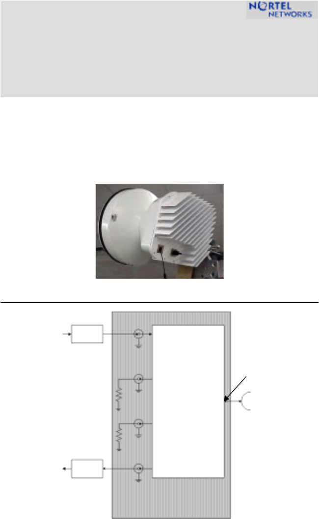
Figure 1: CTR 28M Block Diagram
Rx IF
Tx IF/DC Input
Transceiver
Lightening
Section
Protector
Lightening
Protector
Rx RF Input
(Test
Tx RF Output/
Point ‘A’)
Test Por t
Tx IF Input
Test Por t
Rx IF Output
Output
CTR 28-07M Transceiver

411-1333-921 Draft 01.01 June 2000
2
CTR 28-07 MMIC Specification
Table 1: CTR 28-07M Technical Specifications
TX IF Input RF Output
Frequency Range 28-07M 500-650 MHz 28.20-28.35 GHz
Output Level (P1 dB) ≥23 dBm, -40° to +55° C
Output Level (IP3) +31.0 dBm
Input Impedance 50 Ohms
Input/Output Connector N-Type Female N/A
Gain (not including antenna) 32.0 ±0.6 dB
Gain Variation ±5.0 dB over all conditions
Gain Flatness ±1.9 dB over bandwidth
Frequency Stability <±4 ppm over all conditions
Noise Power -115 dBm/Hz
TX Test Port SMA female
TX IF Test Port Coupling -16±1 dB
Antenna CTR
Frequency 27.5-28.31.3 GHz
Frequency Band 2731
Gain 36.2 dBi, minimum
Polarity Cross Pole (dual polarization)
Beam Width (azimuth)
Beam Width (elevation)
2.5±TBD°, minimum
2.5±TBD°, minimum
Cross-Polarization Discrimination > 30.0 dB
Diameter 14" (35 cm)

CTR 28-07 GHz MMIC Quick Reference Guide
3
RX RF Input IF Output
Frequency Range 28-07M 29.10-29.25 GHz 250-400 MHz
Input/Output Connector N/A N-Type Female
Output Impedance 50 Ohms
Gain (not including antenna) 28±0.6 dB, minimum
Gain Variation ±5.0 dB over all conditions
Gain Flatness ±1.9 dB over bandwidth
Frequency Stability <±4 ppm,over all conditions
Noise Figure ≤ 7.2 dB, maximum
LO Leakage -35 dBm, maximum
RX Test Port SMA female
RX IF Test Port Coupling -14±1 dB
Power Requirements CTR
Input Voltage -48 VDC, 3.5A. max
diplexed with TX cable
Input Current <1.5 Amp
Input Power 55 Watts, maximum
Environmental CTR
Humidity 100% condensing
Altitude 10,000 feet
Wind Resistance 50m/second on all surfaces
Operating Temperature -40° to +55°C
Storage Temperature Range -55° to +70°C
Mechanical CTR
Size (Length x Width) 10.55" x 11.63" (26.4 x 29 cm)
Weight without brackets 25 lbs. (11.1 KG)

Information is subject to change without notice.
Nortel reserves the right to make changes in
design or components as progress in engineering
and manufacturing may warrant.
© 2000 Northern Telecom Ltd.
Converted Frequency Formula
Use the following formula to calculate the converted frequency:
TX: ƒRF OUT (GHz) = 28.85 (GHz) - ƒIF IN (MHz)
RX: ƒIF OUT (MHz) = ƒRF INPUT (GHz) - 28.85 (GHz)
Note: The antenna has an option of a hydrophobic coating that can help to
reduce ice build-up effect.
Note: Vent holes are covered with a GoretexTM patch.
Note: The transceiver mounts to a vertical pole of 2.5” to 4.5” outside diame-
ter. It has a range of motion of 90° over and -60° under horizon. The bases of
the antenna mount can rotate ±180°.
Note: The module connector is N-Type female. The receive IF input/output
cables present a male N-Type connector. The Tx IF and the Rx IF test ports
are SMA-Type female.
Technical Assistance Contact Information
In case additional technical assistance is required, or the transceiver unit is
damaged upon receipt, contact Nortel Networks.
Nortel Networks Broadband Wireless Access (BWA) provides 24-hour customer
service and technical support to ensure your service operation is trouble-free.
If you have questions or need technical support, contact Nortel Networks
Broadband Wireless Access at the following telephone numbers:
• In the USA and Canada, call 972-BWA-ETAS/972-292-3827