Avaya Canada NTE301BA Wireless Access Point User Manual Book
Avaya Canada Corporation Wireless Access Point Book
Installation manual

FINAL April 8th-2005
Part No. 318527-A Rev 01
March 2005
Installing the Nortel Wireless
Access Point 7220

2
318527-A Rev 01
FINAL April 8th-2005
Copyright © 2005 Nortel Networks
All rights reserved. March 2005
The information in this document is subject to change without notice. The statements, configurations, technical data, and
recommendations in this document are believed to be accurate and reliable, but are presented without express or implied
warranty. Users must take full responsibility for their applications of any products specified in this document. The
information in this document is proprietary to Nortel Networks Inc.
The software described in this document is furnished under a license agreement and may be used only in accordance
with the terms of that license. The software license agreement is included in this document.
Trademarks
Nortel Networks, the Nortel Networks logo, the Globemark, Unified Networks, and [other Nortel trademarked product
names] are trademarks of Nortel Networks.
Microsoft, Windows, and Windows NT are trademarks of Microsoft Corporation.
Adobe and Acrobat Reader are trademarks of Adobe Systems Incorporated.
Huber+Suhner is a trademark of Huber+Suhner Incorporated.
Andrew Corporation is a trademark of Andrew Corporation, Inc.
Dow Corning is a trademark of Dow Corning Incorporated.
Ethernet is a trademark of Xerox Corporation.
The asterisk after a name denotes a trademarked item.
Statement of conditions
In the interest of improving internal design, operational function, and/or reliability, Nortel Networks Inc. reserves the
right to make changes to the products described in this document without notice.
Nortel Networks Inc. does not assume any liability that may occur due to the use or application of the product(s) or
circuit layout(s) described herein.
Portions of the code in this software product may be Copyright © 1988, Regents of the University of California. All
rights reserved. Redistribution and use in source and binary forms of such portions are permitted, provided that the
above copyright notice and this paragraph are duplicated in all such forms and that any documentation, advertising
materials, and other materials related to such distribution and use acknowledge that such portions of the software were
developed by the University of California, Berkeley. The name of the University may not be used to endorse or promote
products derived from such portions of the software without specific prior written permission.
SUCH PORTIONS OF THE SOFTWARE ARE PROVIDED “AS IS” AND WITHOUT ANY EXPRESS OR IMPLIED
WARRANTIES, INCLUDING, WITHOUT LIMITATION, THE IMPLIED WARRANTIES OF MERCHANTABILITY
AND FITNESS FOR A PARTICULAR PURPOSE.
In addition, the program and information contained herein are licensed only pursuant to a license agreement that contains
restrictions on use and disclosure (that may incorporate by reference certain limitations and notices imposed by third
parties).

3
Installing the Nortel Wireless Access Point 7220
FINAL April 8th-2005
Regulatory Statements
This device is designed for installation and use in the USA, Canada, China and Taiwan regulatory rules. For operation in
other countries, please consult Nortel Networks.
This device contains one radio operating in the 2.4 GHz band and one radio operating in the 5 GHz bands in
point-to-point fashion.
Regulatory statements pursuant to CFR 47 Part 15 for the United States
This device complies with Part 15 of the FCC Rules. Operation is subject to the following two conditions: (1) this device
may not cause harmful interference, and (2) this device must accept any interference received, including interference
that may cause undesired operation.
Federal Communications Commission (FCC) Compliance Notice: Radio Frequency Notice
Note: This equipment has been tested and found to comply with the limits for a Class B digital device, pursuant to Part
15 of the FCC Rules. These limits are designed to provide reasonable protection against harmful interference in a
residential installation. This equipment generates, uses and can radiate radio frequency energy and, if not installed and
used in accordance with the instructions, may cause harmful interference to radio communications. However, there is no
guarantee that interference will not occur in a particular installation.
If this equipment does cause harmful interference to radio or television reception, which can be determined by turning
the equipment off and on, the user is encouraged to try to correct the interference by one or more of the following
measures:
- Re-orient or relocate the receiving antenna.
- Increase the separation between the equipment and receiver.
- Connect the equipment into an outlet on a circuit different from that to which the receiver is connected.
- Consult the dealer or an experienced radio/TV technician for help.
The installation and operation of this device shall be in strict compliance with the manufacturer's instructions for its
installation and use. Any changes in the installation, or modification of the device or of its optional accessories that are
not expressly approved by the manufacturer and the party responsible for compliance could void the user's authority to
operate the device.
Only those optional accessories listed in the operating manual shall be used with this device. The use of any other
accessories (including antennas) will void the warranty and the user's authority to operate the device.
The manufacturer is not responsible for interference to other radio systems caused by the use of this device or by any
unauthorized modification to the device or its associated antennas. The manufacturer assumes no liability for any
damage or violation of regulations arising from the use of the device.
This device is designed to be installed by professionals trained in its installation and who are responsible for compliance
with the relevant regulations.
This device is designed for installation in fixed locations only.
This device is not designed for direct connection to the public switched telephone network.
Note: The use of external RF amplifiers with this device is not permitted by the regulations of the FCC.
This unit is not a consumer product and requires professional network planning and installation. As such, this device is
limited for use with approved antennas only.
Note: The use of non-approved antennas, tampering with, or deviating from the approved deployment configurations is
strictly prohibited and could result in FCC/IC (Industry Canada) regulatory violations.

4
318527-A Rev 01
FINAL April 8th-2005
Regulatory statements pursuant to RSS-210/CNR-210 for Canada
AVIS: Le texte en français suit ci-dessous.
Operation (of this device) is subject to the following two conditions: (1) this device may not cause interference and (2)
this device must accept any interference, including interference that may cause undesired operation of the device. To
reduce the potential of radio interference to other users, the antenna type and its gain should be chosen so that the
equivalent isotropically radiated power (EIRP) is not more than that required for successful communication.
This Class B digital apparatus meets all the requirements of the Canadian Interference Causing Equipment Standard 003
(ICES-003).
Note: The use of external RF amplifiers with this device is strictly forbidden by the regulations of Industry Canada.
This device has been designed to operate with a optional external 5GHz antenna having a maximum gain of 23.0 dBi.
Operation with antennas having a higher gain is strictly prohibited by the regulations of Industry Canada. The required
antenna impedance is 50 ohms.
This device has been designed to operate with a 2.4GHz antenna having a maximum gain of 4.0 dBi. Operation with
antennas having a higher gain is strictly prohibited by the regulations of Industry Canada. The required antenna
impedance is 50 ohms.
The installer of this radio equipment must ensure that the antenna is located or pointed such that it does not create an RF
field in excess of Health Canada limits for the general population; consult Safety Code 6, obtainable from Health
Canada's website www.hcsc.gc.ca/rpb.
This unit is not a consumer product and requires professional network planning and installation. As such, this device is
limited for use with approved antennas only.
Note: the use of non-approved antennas, tampering with, or deviating from the approved deployment configurations is
strictly prohibited and could result in FCC/IC regulatory violations.
L'utilisation de ce dispositif est autorisée seulement aux conditions suivantes : (1) il ne doit pas produire de brouillage et
(2) l'utilisateur du dispositif doit être prêt à accepter tout brouillage radioélectrique reçu, même si ce brouillage est
susceptible de compromettre le fonctionnement du dispositif.
Afin de réduire le risque d'interférence aux autres utilisateurs, le type d'antenne et son gain doivent être choisis de façon
à ce que la puissance isotrope rayonnée équivalente (p.i.r.e.) ne soit pas supérieure au niveau requis pour obtenir une
communication satisfaisante.
Cet appareil numérique respecte les limites de bruits radioélectriques applicables aux appareils numériques de la class B
prescrites dans la norme sur le matériel brouilleur "Appareils Numeriques" (NMB-003) édictée par le ministère des
Communications du Canada
ATTENTION: L'utilisation d'amplificateurs RF externes avec les dispositifs de faible puissance est strictement interdit.
Ce dispositif a été conçu pour fonctionner avec une antenne optionnelle de 5GHz ayant un gain maximal de 23.0 dBi.
Une antenne ayant un gain plus élevé est strictement interdit par les règlements d'Industrie Canada. L'impédance
d'antenne requise est 50 ohms.
Ce dispositif a été conçu pour fonctionner avec une antenne de 2.4GHz ayant un gain maximal de 4.0 dBi. Une antenne
ayant un gain plus élevé est strictement interdit par les règlements d'Industrie Canada. L'impédance d'antenne requise est
50 ohms.
L'installateur du présent matériel radio doit s'assurer que l'antenne est située ou pointée de manière à ce que cette
dernière n'émettre pas de champs radioélectriques supérieurs aux limites spécifiées par Santé Canada pour le grand
public; consulter le Code de sécurité 6, disponible sur le site Web de Santé Canada, à l'adresse suivante: www.hcsc.gc.ca/
rpb.
Cet appareil est seulement pour usage commercial et requiert une installation professionnelle certifiée. L'usage de cet
appareil est limité aux antennes certifiées stipulées par le fabricant.

5
Installing the Nortel Wireless Access Point 7220
FINAL April 8th-2005
ATTENTION: L'usage d'antennes autres que stipulées par le fabricant est prohibé et peut résulter en une violation des
critères d'approbation FCC et Industrie Canada pour lequel cet appareil est homologué.
General Installation Considerations
This device has been evaluated and found to be compliant to the requirements addressing RF exposure from radio
frequency devices for an uncontrolled environment. The RF emissions of this device are below the FCC limits.
However, it is nevertheless generally advisable that radio transmitting equipment should always be installed and used in
a manner so as to minimise exposure during normal operation.
When the unit is installed using integral 5GHz antennas with integral or external 2.4GHz antennas, the product shall be
installed in a fixed location with a minimum separation of 0.5 metre from all persons during normal use and shall be
used only with approved accessories listed in this manual.
When the unit is installed using optional external 5GHz antennas (13 dBi and 18dBi), the product shall be installed in a
fixed location with a minimum separation of 50 cm from all persons during normal use and shall be used with approved
accessories listed in this manual.
When the unit is installed using optional external 5GHz antennas (23 dBi), the product shall be installed in a fixed
location with a minimum separation of 100 cm from all persons during normal use and shall be used with approved
accessories listed in this manual.
Installation with external 5GHz antennas (13 dBi and 18 dBi) are qualified for indoor and outdoor use. The 23 dBi
antenna is qualified for outdoor use only. This unit operates in point-to-point fashion only in 5GHz band.
Nortel Networks Inc. software license agreement
This Software License Agreement (“License Agreement”) is between you, the end-user (“Customer”) and Nortel
Networks Corporation and its subsidiaries and affiliates (“Nortel Networks”). PLEASE READ THE FOLLOWING
CAREFULLY. YOU MUST ACCEPT THESE LICENSE TERMS IN ORDER TO DOWNLOAD AND/OR USE THE
SOFTWARE. USE OF THE SOFTWARE CONSTITUTES YOUR ACCEPTANCE OF THIS LICENSE
AGREEMENT. If you do not accept these terms and conditions, return the Software, unused and in the original shipping
container, within 30 days of purchase to obtain a credit for the full purchase price.
“Software” is owned or licensed by Nortel Networks, its parent or one of its subsidiaries or affiliates, and is copyrighted
and licensed, not sold. Software consists of machine-readable instructions, its components, data, audio-visual content
(such as images, text, recordings or pictures) and related licensed materials including all whole or partial copies. Nortel
Networks grants you a license to use the Software only in the country where you acquired the Software. You obtain no
rights other than those granted to you under this License Agreement. You are responsible for the selection of the
Software and for the installation of, use of, and results obtained from the Software.
1. Licensed Use of Software. Nortel Networks grants Customer a nonexclusive license to use a copy of the Software
on only one machine at any one time or to the extent of the activation or authorized usage level, whichever is applicable.
Software is not transferable, or applicable, or entitled to third parties on subsequent resale of the equipment. To the
extent Software is furnished for use with designated hardware or Customer furnished equipment (“CFE”), Customer is
granted a nonexclusive license to use Software only on such hardware or CFE, as applicable. Software contains trade
secrets and Customer agrees to treat Software as confidential information using the same care and discretion Customer
uses with its own similar information that it does not wish to disclose, publish or disseminate. Customer will ensure that
anyone who uses the Software does so only in compliance with the terms of this Agreement. Customer shall not a) use,
copy, modify, transfer or distribute the Software except as expressly authorized; b) reverse assemble, reverse compile,
reverse engineer or otherwise translate the Software; c) create derivative works or modifications unless expressly
authorized; or d) sublicense, rent or lease the Software. Licensors of intellectual property to Nortel Networks are
beneficiaries of this provision. Upon termination or breach of the license by Customer or in the event designated
hardware or CFE is no longer in use, Customer will promptly return the Software to Nortel Networks or certify its

6
318527-A Rev 01
FINAL April 8th-2005
destruction. Nortel Networks may audit by remote polling or other reasonable means to determine Customer’s Software
activation or usage levels. If suppliers of third party software included in Software require Nortel Networks to include
additional or different terms, Customer agrees to abide by such terms provided by Nortel Networks with respect to such
third party software.
2. Warranty. Except as may be otherwise expressly agreed to in writing between Nortel Networks and Customer,
Software is provided “AS IS” without any warranties (conditions) of any kind. NORTEL NETWORKS DISCLAIMS
ALL WARRANTIES (CONDITIONS) FOR THE SOFTWARE, EITHER EXPRESS OR IMPLIED, INCLUDING,
BUT NOT LIMITED TO THE IMPLIED WARRANTIES OF MERCHANTABILITY AND FITNESS FOR A
PARTICULAR PURPOSE AND ANY WARRANTY OF NON-INFRINGEMENT. Nortel Networks is not obligated to
provide support of any kind for the Software. Some jurisdictions do not allow exclusion of implied warranties, and, in
such event, the above exclusions may not apply.
3. Limitation of Remedies. IN NO EVENT SHALL NORTEL NETWORKS OR ITS AGENTS OR SUPPLIERS BE
LIABLE FOR ANY OF THE FOLLOWING: a) DAMAGES BASED ON ANY THIRD PARTY CLAIM; b) LOSS OF,
OR DAMAGE TO, CUSTOMER’S RECORDS, FILES OR DATA; OR c) DIRECT, INDIRECT, SPECIAL,
INCIDENTAL, PUNITIVE, OR CONSEQUENTIAL DAMAGES (INCLUDING LOST PROFITS OR SAVINGS),
WHETHER IN CONTRACT, TORT OR OTHERWISE (INCLUDING NEGLIGENCE) ARISING OUT OF YOUR
USE OF THE SOFTWARE, EVEN IF NORTEL NETWORKS, ITS AGENTS OR SUPPLIERS HAVE BEEN
ADVISED OF THEIR POSSIBILITY. The forgoing limitations of remedies also apply to any developer and/or supplier
of the Software. Such developer and/or supplier is an intended beneficiary of this Section. Some jurisdictions do not
allow these limitations or exclusions and, in such event, they may not apply.
4. General
a. If Customer is the United States Government, the following paragraph shall apply: All Nortel Networks
Software available under this License Agreement is commercial computer software and commercial computer
software documentation and, in the event Software is licensed for or on behalf of the United States
Government, the respective rights to the software and software documentation are governed by Nortel
Networks standard commercial license in accordance with U.S. Federal Regulations at 48 C.F.R. Sections
12.212 (for non-DoD entities) and 48 C.F.R. 227.7202 (for DoD entities).
b. Customer may terminate the license at any time. Nortel Networks may terminate the license if Customer fails
to comply with the terms and conditions of this license. In either event, upon termination, Customer must
either return the Software to Nortel Networks or certify its destruction.
c. Customer is responsible for payment of any taxes, including personal property taxes, resulting from
Customer’s use of the Software. Customer agrees to comply with all applicable laws including all applicable
export and import laws and regulations.
d. Neither party may bring an action, regardless of form, more than two years after the cause of the action arose.
e. The terms and conditions of this License Agreement form the complete and exclusive agreement between
Customer and Nortel Networks.
f. This License Agreement is governed by the laws of the country in which Customer acquires the Software. If
the Software is acquired in the United States, then this License Agreement is governed by the laws of the state
of New York.

1
Installing the Nortel Wireless Access Point 7220
DRAFT March 24th-2005
Contents
Chapter 1
Installing the Wireless AP 7220 . . . . . . . . . . . . . . . . . . . . . . . . . . . . . . . . . . . 9
Limitations and restrictions . . . . . . . . . . . . . . . . . . . . . . . . . . . . . . . . . . . . . . . . . . . . . . 9
Safety guidelines . . . . . . . . . . . . . . . . . . . . . . . . . . . . . . . . . . . . . . . . . . . . . . . . . . . . . . 9
Installation flowchart . . . . . . . . . . . . . . . . . . . . . . . . . . . . . . . . . . . . . . . . . . . . . . . . . . . 10
Installing the Wireless AP 7220 . . . . . . . . . . . . . . . . . . . . . . . . . . . . . . . . . . . . . . . . . . 11
Verifying the package contents . . . . . . . . . . . . . . . . . . . . . . . . . . . . . . . . . . . . . . . 12
Recording the serial number . . . . . . . . . . . . . . . . . . . . . . . . . . . . . . . . . . . . . . . . . 12
Installing the mechanical support . . . . . . . . . . . . . . . . . . . . . . . . . . . . . . . . . . . . . 12
Installing the mechanical support on a pole . . . . . . . . . . . . . . . . . . . . . . . . . . 12
Installing the mechanical support on a wall or ceiling . . . . . . . . . . . . . . . . . . . 13
Preparing the Wireless AP 7220 . . . . . . . . . . . . . . . . . . . . . . . . . . . . . . . . . . . . . . 13
Connecting an Ethernet cable to a Wireless AP 7220 @ NAP . . . . . . . . . . . . 13
Completing the Wireless AP 7220 preparation . . . . . . . . . . . . . . . . . . . . . . . . 15
Connecting the power cable . . . . . . . . . . . . . . . . . . . . . . . . . . . . . . . . . . . . . . . . . 16
Attaching the Wireless AP 7220 to the base plate adaptor . . . . . . . . . . . . . . . . . . 17
Installing an external co-linear antenna . . . . . . . . . . . . . . . . . . . . . . . . . . . . . . . . . 18
Verifying correct operation through the LED indicators . . . . . . . . . . . . . . . . . . . . . 19
Appendix A
Wireless AP 7220 materials checklist . . . . . . . . . . . . . . . . . . . . . . . . . . . . . 21
Wireless AP 7220 materials checklist . . . . . . . . . . . . . . . . . . . . . . . . . . . . . . . . . . . . . 21
Appendix B
Physical installation requirements. . . . . . . . . . . . . . . . . . . . . . . . . . . . . . . . 23
Physical installation requirements . . . . . . . . . . . . . . . . . . . . . . . . . . . . . . . . . . . . . . . . 23
Location . . . . . . . . . . . . . . . . . . . . . . . . . . . . . . . . . . . . . . . . . . . . . . . . . . . . . . . . . 23
Supplying AC power . . . . . . . . . . . . . . . . . . . . . . . . . . . . . . . . . . . . . . . . . . . . . . . 23
Installation scenarios . . . . . . . . . . . . . . . . . . . . . . . . . . . . . . . . . . . . . . . . . . . . . . . 24

2
318527-A Rev 01
DRAFT March 24th-2005
Appendix C
Getting technical manuals and support . . . . . . . . . . . . . . . . . . . . . . . . . . . 25
How to get technical manuals . . . . . . . . . . . . . . . . . . . . . . . . . . . . . . . . . . . . . . . . . . . 25
How to get support . . . . . . . . . . . . . . . . . . . . . . . . . . . . . . . . . . . . . . . . . . . . . . . . . . . . 25
1
Installing the Nortel Wireless Access Point 7220
DRAFT March 24th-2005
Installing the Wireless AP 7220
Limitations and restrictions
Safety guidelines
Use the following safety guidelines to ensure your own personal safety and to help
protect your Wireless AP 7220 unit from potential damage.
The Wireless AP 7220 is safety-certified as a free-standing unit and as a
component for use indoors or outdoors when installed using certified components
and accessories according to the instructions and observing the limitations
detailed in this manual.
The product must be installed in compliance with all local safety and electrical
codes. The manufacturer disclaims all warranties and liability in connection with
installation methods not described in this manual and/or installations that do not
comply with local safety codes and regulations. This device is designed to be
installed by professionals trained in its installation and who are responsible for
compliance with the relevant regulations.
Warning: THE WIRELESS AP 7220 IS A SEALED DEVICE INTENDED FOR
PROFESSIONAL INSTALLATION BY A QUALIFIED INSTALLER FOR
INDUSTRIAL/COMMERCIAL USE. THERE ARE NO USER-SERVICEABLE
COMPONENTS INSIDE.
TO AVOID ELECTRICAL SHOCK OR BODILY INJURY DO NOT TAMPER WITH
OR ATTEMPT TO OPEN THIS DEVICE.
2
318527-A Rev 01
DRAFT March 24th-2005
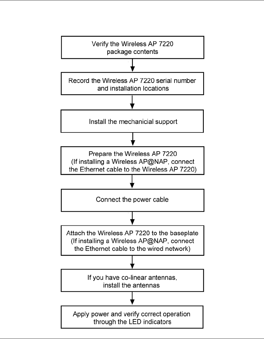
Installation flowchart
Figure 1 Installing the Wireless AP 7220 flowchart
3
Installing the Nortel Wireless Access Point 7220
DRAFT March 24th-2005
Installing the Wireless AP 7220
Use the Wireless AP 7220 mechanical support to mount the Wireless AP 7220
vertically or horizontally on a:
• horizontal pole
• vertical pole
• wall (side of a building)
• ceiling
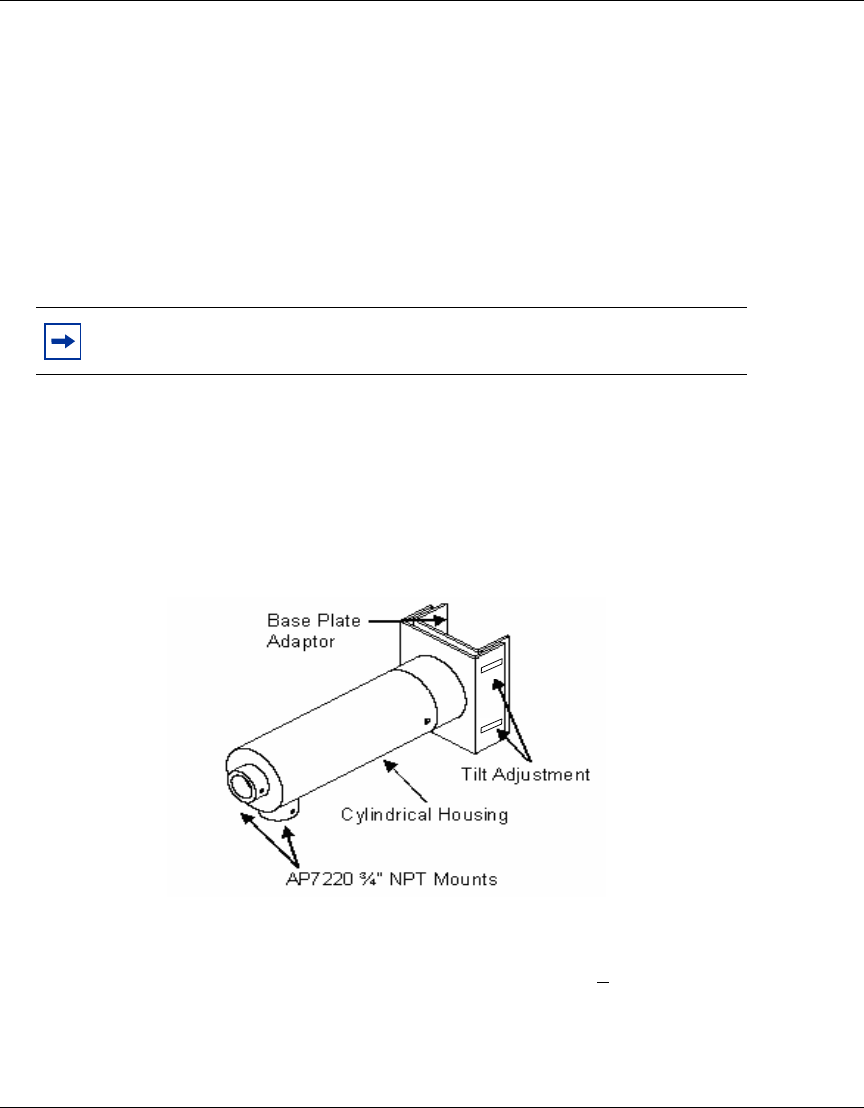
The mechanical support consists of three major components (see Figure 2):
• base plate adaptor (shown) and pole band clamps (not shown)
• cylindrical housing
• inner wiring / divider arm inside the cylindrical housing
Figure 2 Wireless AP 7220 mechanical support
Use the band clamps to fix the mechanical support to the horizontal or vertical
pole. The mechanical support allows adjustment of + 20 degrees to accommodate
a pole that is tapered or offset from the vertical or horizontal mounting plane.
Note: Please read all instructions prior to installation.

4
318527-A Rev 01
DRAFT March 24th-2005
Verifying the package contents
1Verify the contents of the Wireless AP 7220 and mechanical support
packages. For a detailed list of standard package contents and available
accessories see Appendix A, “Wireless AP 7220 materials checklist”.
Recording the serial number
2Record the serial number and the installation location of the Wireless AP
7220. These records are required for subsequent network management and
maintenance.
Installing the mechanical support
3Select the location for the Wireless AP 7220 and unpack the mounting
hardware kit.
4Remove the cylindrical housing of the mechanical support by loosening the
two set screws and sliding the cylindrical housing away from the base plate
adaptor.
You can install the mechanical support on:
• a pole (horizontal or vertical). To install the mechanical support on a pole,
go to the section “Installing the mechanical support on a pole
• a wall or ceiling. To install the mechanical support on a wall or ceiling, go
to the section “Installing the mechanical support on a wall or ceiling.
Installing the mechanical support on a pole
5Fasten the base plate adaptor to the pole by inserting the three band clamps
through the slotted openings and around the pole. Mount the base plate
adaptor to the pole with the U-bracket opening towards the pole.
6Adjust and tighten the base plate adaptor securely to the pole by tightening the
band clamps such that no movement is possible.
Note: To facilitate installation, installers may remove the base plate adaptor from the
mount by removing the four adjustment screws located on the base plate U-bracket.

5
Installing the Nortel Wireless Access Point 7220
DRAFT March 24th-2005
The mount is now securely fastened to the pole. To continue the installation, go to
the section “Preparing the Wireless AP 7220
Installing the mechanical support on a wall or ceiling
The base plate adaptor is reversible for wall and ceiling installations.
7Remove the four adjustment screws on the base plate adaptor and secure the
flat side of the adaptor on the mounting surface (wall or ceiling) using
appropriate anchors to support the weight and wind loads.
8Re-attach the inner arm on the installed base plate adaptor using the four
adjustment screws removed previously.
The mount is now securely fastened to the wall/ceiling. To continue the
installation, go to the section “Preparing the Wireless AP 7220
Preparing the Wireless AP 7220
On the ground, install the Wireless AP 7220 on the cylindrical mount (vertical or
horizontal) via the ¾ NPT opening.
9Loosen (back off) the NPT anti-rotation set screw.
10 Remove the appropriate ¾ NPT plastic plugs from the mount.
If you are installing a Wireless AP 7220@NAP, proceed to the section
“Connecting an Ethernet cable to a Wireless AP 7220 @ NAP.
If you are installing a standalone Wireless AP 7220, skip to the section
“Completing the Wireless AP 7220 preparation
Connecting an Ethernet cable to a Wireless AP 7220 @ NAP
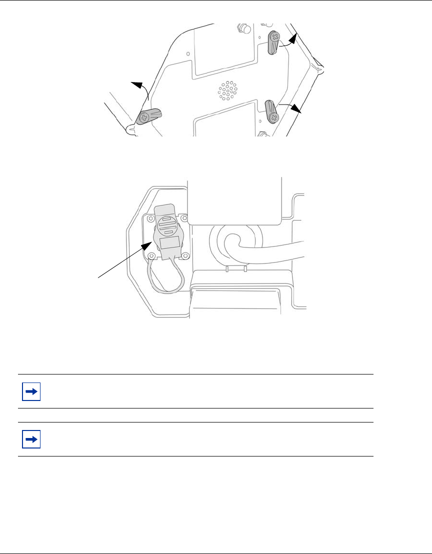
11 Remove the baseplate cover of the Wireless AP 7220 @ NAP cabling
compartment by pivoting open the three tabs holding the cover in place.
6
318527-A Rev 01
DRAFT March 24th-2005
Figure 3 Open cabling compartment
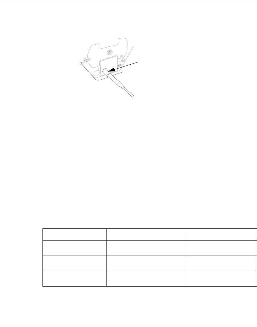
12 Remove the Ethernet port protective cover from the cabling compartment.
Figure 4 Remove Ethernet port protective cover
13 Pull back the unattached end of the AC power cable from the central support
pipe until it is free of the shaft. This will make it easier to feed the Ethernet
cable up through the support pipe.
14 Slide the non-connectorized end of the CAT 5 Ethernet cable up through the
main support pipe of the Wireless AP 7220 @ NAP and out of the side hole of
the cylindrical arm. This cable will be used to provide a wired connection to
the NAP.
Note: Do not disconnect the AC power connector from the Wireless AP 7220 @ NAP.
Note: The CAT5 cable has a connector at one end. This connector attaches to the
Ethernet jack at the base of the Wireless AP 7220 @ NAP unit.
Ethernet port cover
7
Installing the Nortel Wireless Access Point 7220
DRAFT March 24th-2005
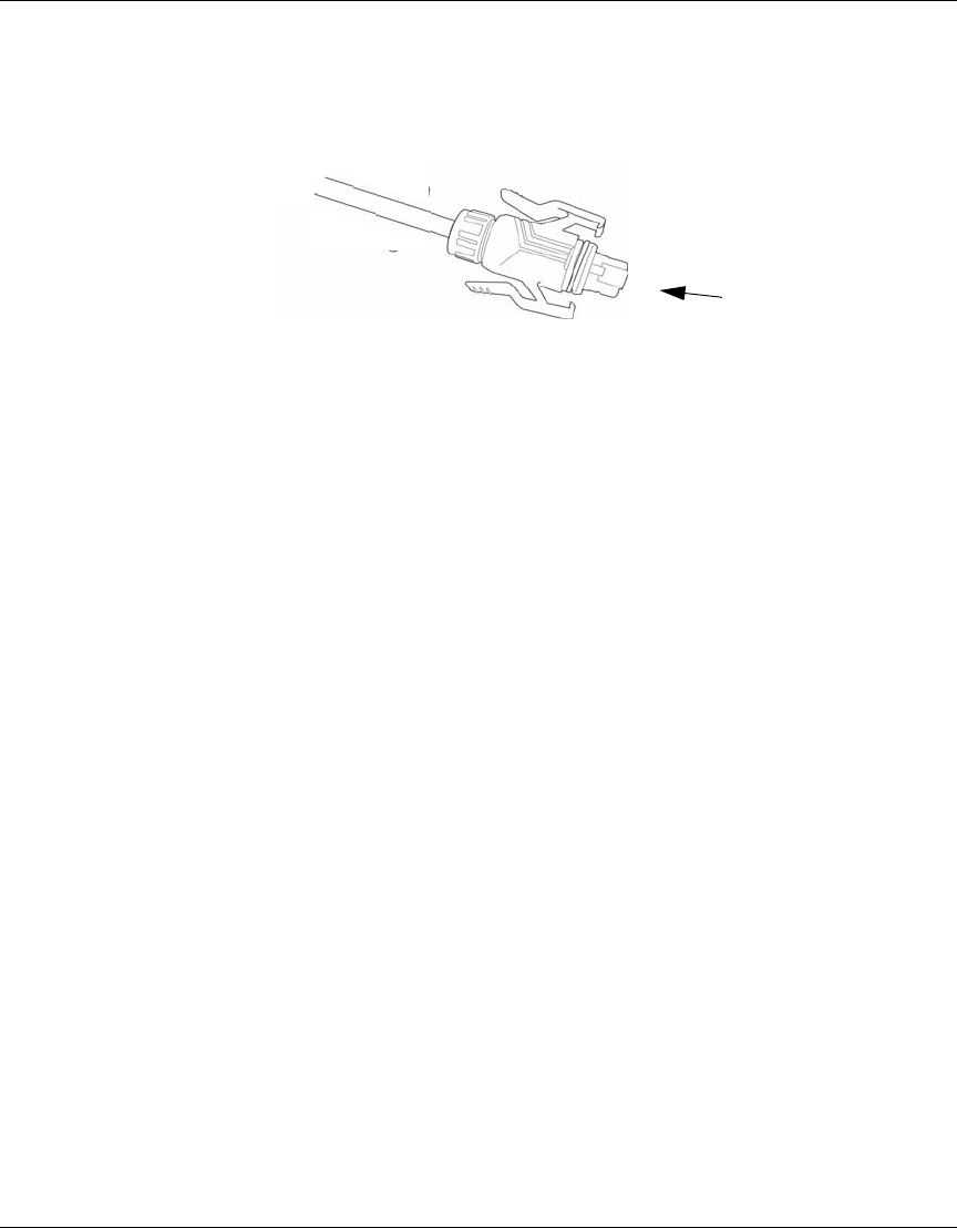
15 Attach the connector to the Ethernet jack at the base of the Wireless AP 7220
@ NAP unit.
Figure 5 CAT5 connectorized cable end
16 Feed the power cable back up through the main support pipe until it emerges
from the cylindrical housing.
17 Replace the metal baseplate cover of the Wireless AP 7220 @ NAP by
pivoting shut the three tabs used to hold the cover in place.
Completing the Wireless AP 7220 preparation
18 Feed the Wireless AP 7220 AC wire (and, in the case of a Wireless AP
7220@NAP, the Ethernet cable) into the ¾ NPT port and up through the
cylindrical arm.
19 Screw the Wireless AP 7220 to the cylindrical arm until secure (do not over
tighten).
The wiring should extend beyond the cylinder mount to facilitate wiring to the
terminal strip located on the inner arm.
The Wireless AP 7220 and cylindrical arm are now ready to attach and wire to the
base plate adaptor on the pole.
Ethernet connector
8
318527-A Rev 01
DRAFT March 24th-2005
Connecting the power cable
To facilitate the next steps, hang the Wireless AP 7220 and attached cylindrical
arm from the base plate adaptor. Small holes are provided on the inner arm and
arm housing for an "S" hook to support the Wireless AP 7220 assembly.
20 Install an electrical switch, fuse, or circuit breaker at an accessible point
between the power mains and the Wireless AP 7220 to facilitate power cut-off
to the Wireless AP 7220 for maintenance purposes.
21 Access the base plate adaptor on the pole. With electrical power removed,
pre-wire the inner arm AC power using an approved water tight feed through
on the base of the mount and connect the individual line and neutral
conductors to the terminal strip provided on the inner wiring arm.
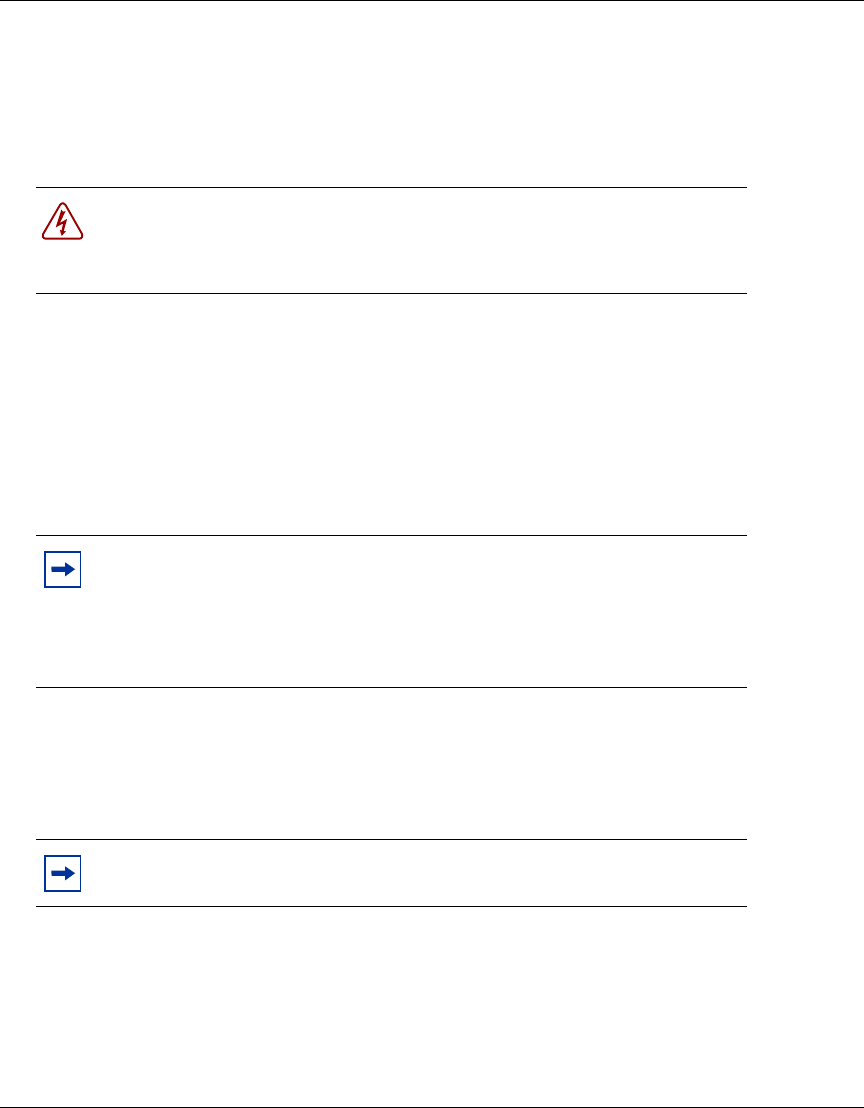
22 Connect the GND wire from the AC power feed to a #10 ring terminal (see
Figure 6). Attach the ring terminal to the GND stud on the inner wiring arm
and secure with the external tooth lock washers and 10-32 nut provided. (the
lock washers are installed each side of the ring terminal).
Danger: The external power cable connects to the source which will power the
Wireless AP 7220.
Ensure that no power is coming through this cable when performing the procedure.
Note: For Wireless AP 7220@ NAP installations, pass the Ethernet feed from the
Wireless AP 7220 along the side of the inner arm opposite the wiring connections, and
exit at the base of the support through an approved water tight feed through
The purpose of the inner arm / divider is to separate the AC wiring from the Ethernet
communication feed
Note: The GND stud is pre-wired to the GND on the terminal strip via a short lead.
9
Installing the Nortel Wireless Access Point 7220
DRAFT March 24th-2005
Figure 6 Wiring the Wireless AP 7220 to the mechanical support inner arm
23 Attach the Wireless AP 7220 black wire to the correct position on the terminal
strip. Connect the neutral wire to the neutral position on the terminal strip and
the GND (green wire) to the GND position on the terminal strip.
Attaching the Wireless AP 7220 to the base plate adaptor
24 With wiring complete, slide the cylindrical housing (with Wireless AP 7220
attached) over the inner arm.
25 Align and secure the cylindrical housing with the two set screws located at the
base.
26 Verify the alignment of the vertical and horizontal and adjust if required.
To adjust the alignment, loosen the four adjustment screws on the base plate
adaptor and align the unit in the vertical or horizontal as required.
Tighten the four adjustment screws to secure the alignment.
10
318527-A Rev 01
DRAFT March 24th-2005
27 To complete the installation, securely tighten all anti-rotation screws and
adjustment screws. Ensure the unused ¾ NPT port is capped securely with the
plug provided.
If you are installing external co-linear antennas, proceed to the section
“Installing an external co-linear antenna.
If you are not installing external co-linear antennas, skip to the section
“Verifying correct operation through the LED indicators
Installing an external co-linear antenna
28 If you have a Wireless AP 7220 with integrated 2.4 GHz antennas instead of
co-linear antennas, skip to step 36.
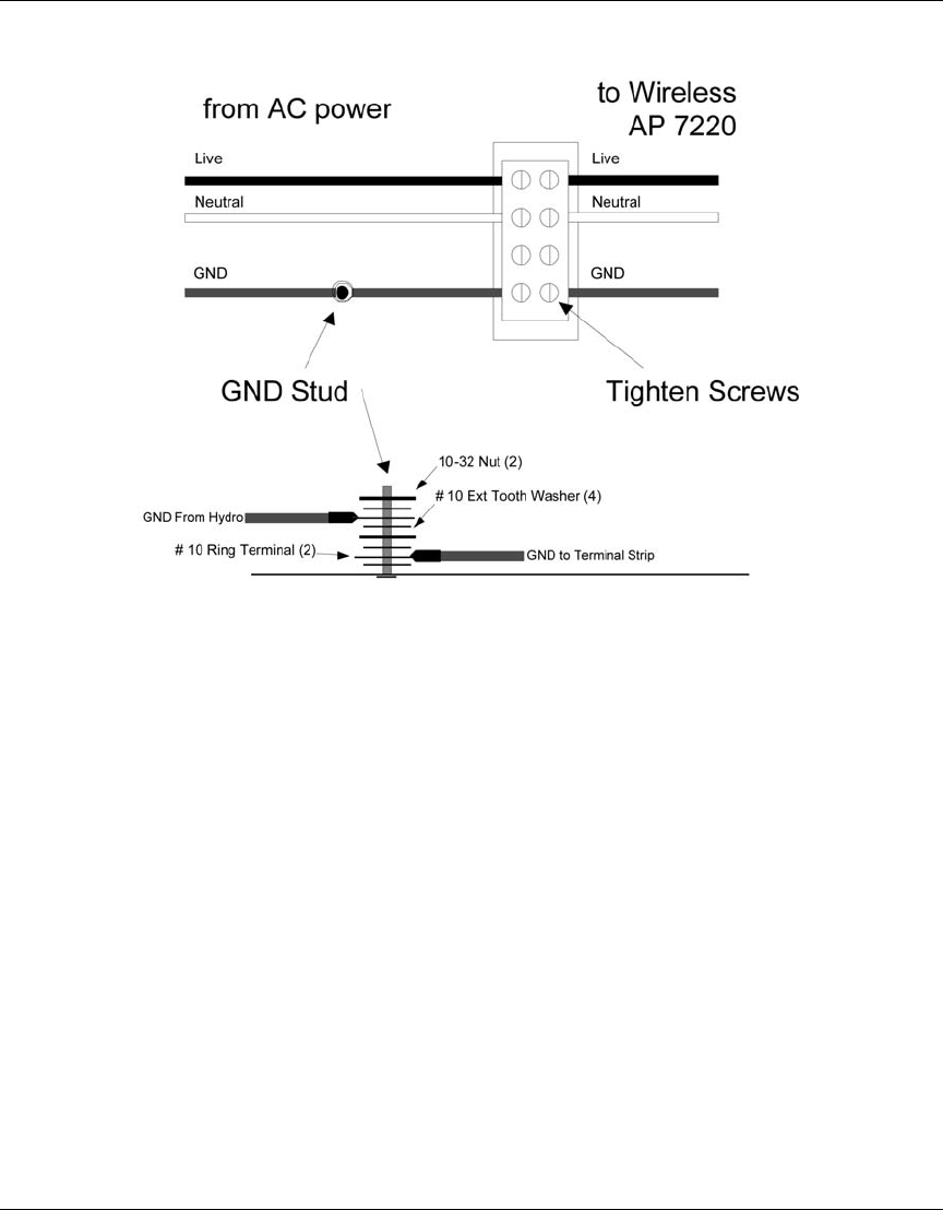
29 Screw the co-linear antenna firmly onto the Wireless AP 7220 base antenna
connector.
Figure 7 Attaching the co-linear antenna
30 Slip the protective rubber boot over the antenna and 3/4 of the way to its base.
31 Apply protective grease around the underside of the boot to ensure a good
seal.
Note: Nortel Networks recommends Dow Corning* 111 silicon for use as a protective
grease.
11
Installing the Nortel Wireless Access Point 7220
DRAFT March 24th-2005
32 Slip the protective rubber boot the remainder of the way to the base of the
antenna.
Figure 8 Install the protective boots
33 Ensure that the protective boot is firmly in place.
34 Repeat steps 29 to 33 with the second antenna.
Verifying correct operation through the LED indicators
35 If installing a Wireless AP 7220@NAP, run the Ethernet cable to the desired
Ethernet feeder and splice using standard connectors.
36 Apply power to the Wireless AP 7220 unit.
The LED at the bottom of the unit turns red indicating the unit is powering up.
Consult Table 1 to interpret the different LED states for a standalone Wireless
AP 7220 or Table 2 to interpret the different LED states for a Wireless AP
7220 @ NAP.
Table 1 Standalone Wireless AP 7220 LED Indicators
LED Pattern Status Description
Solid Red Power-up/Initializing Basic Services not yet
initialized
Alternating Red/Amber Initialized + No Transit Link Initialized but no Transit Link
Neighbors Detected
Alternating Red/Green Initialized + Transit Link
Detected 1 or more neighbors
detected
antenna boot
12
318527-A Rev 01
DRAFT March 24th-2005
Solid Amber Initialized + Transit Link up +No
service 1 or more Transit Links
established but no Wireless
Gateway 7250 connection
Solid Green Initialized + Transit Link up +
Fully Operational 1 or more Transit Links
established and Wireless
Gateway connection
successfully established
Table 2 Wireless AP 7220 @ NAP LED Indicators
LED Pattern Status Description
Solid Red Power-up/Initializing Basic Services not yet
initialized
Solid Amber Initialized + No service Initialized but no Wireless
Gateway 7250 connection
Solid Green Initialized + Fully Operational Initialized and Wireless
Gateway 7250 connection
successfully established
Table 1 Standalone Wireless AP 7220 LED Indicators
LED Pattern Status Description

1
Installing the Nortel Wireless Access Point 7220
DRAFT March 24th-2005
Appendix A
2
318527-A Rev 01
DRAFT March 24th-2005
Wireless AP 7220 materials checklist
Wireless AP 7220 materials checklist
Table 3 lists the contents of the Wireless AP 7220 standard packages. Figure 9 and
Figure 10 show the standard package contents. The standard package includes
parts suitable for the majority of installations. Additional site-specific accessories
may be required prior to installation. Should any additional accessories or custom
configurations be required, please contact 1-800-4NORTEL.
Table 3 Wireless AP 7220 materials checklist (standard package contents)
Wireless AP 7220 standard package contents
PEC: NTE300BG PEC: NTE350BG
Wireless Access Point 7220 with attached power
cable and integrated 2.4 GHz antennas Wireless Access Point 7220 with attached power
cable
Installation card Installation card
-two co-linear 2.4 GHz antennas
-two antenna protective weatherproofing boots
3
Installing the Nortel Wireless Access Point 7220
DRAFT March 24th-2005
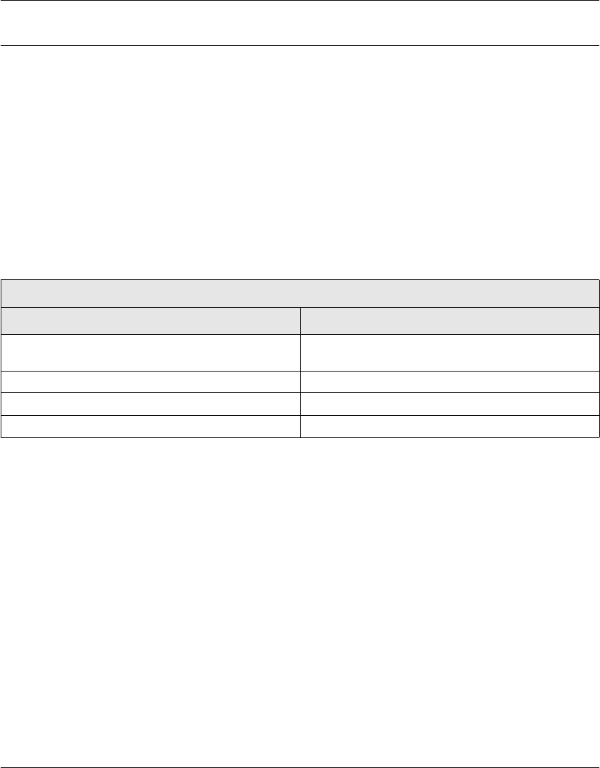
Figure 9 Standard package contents (integrated 2.4 GHz antenna) - PEC: NTE300BG
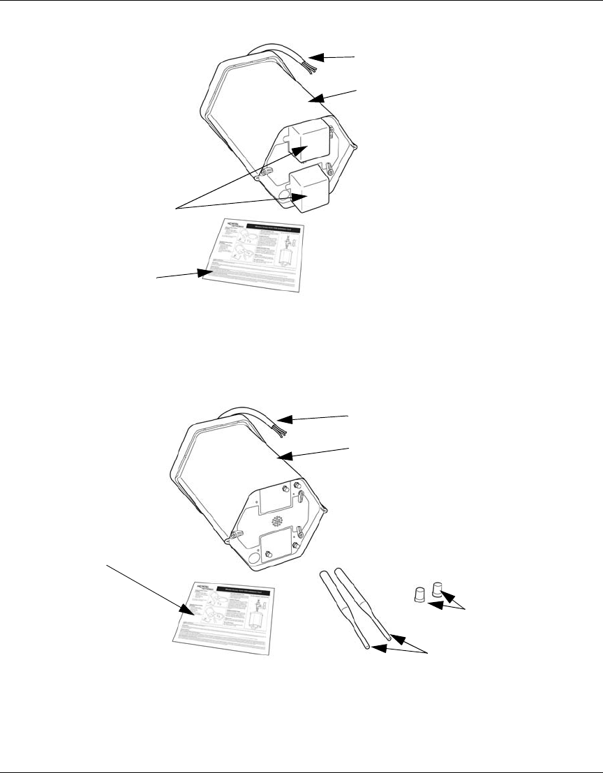
Figure 10 Standard package contents (co-linear antennas) - PEC: NTE350BG
integral 2.4 GHz antennas
Installation Card
Wireless AP 7220 unit (Model: NTE301BG
)
power cable
Installation Card
Wireless AP 7220 unit (Model: NTE301BG)
power cable
antenna
protective
boots
co-linear
antennas

4
318527-A Rev 01
DRAFT March 24th-2005

1
Installing the Nortel Wireless Access Point 7220
DRAFT March 24th-2005
Appendix B

2
318527-A Rev 01
DRAFT March 24th-2005
Physical installation requirements
Physical installation requirements
The Wireless AP 7220 unit is designed to be installed vertically with the baseplate
facing down (in indoor or outdoor locations). The unit must be installed in
accordance with pre-installation activities, site survey, local electrical codes and
regulatory requirements. Record the serial number and the location of each unit.
These records are required for subsequent network management and maintenance.
Location
When installing the Wireless AP 7220 unit choose a location that:
• provides a minimum separation of 0.5 metre from all persons during normal
operation for units installed using integral 5GHz (13 and 18 dBi)antennas
with integral or external 2.4GHz antennas for regulatory compliance.
• provides a minimum separation of 1 metre from all persons during normal
operation for units installed using optional approved external 5GHz (23 dBi)
antennas for regulatory compliance.
• approved external 5GHz antennas (13 dBi and 18 dBi) are qualified for indoor
and outdoor use except for the 23 dBi which is qualified for outdoor
installation only.
• minimizes the possibility of vandalism or accidental harm to the unit.
• has line of sight with neighboring units.
Supplying AC power
The Wireless AP 7220 must be powered from AC supplies in the range
100V-240V and 45Hz-65Hz. A continuous supply of power is required for
operation of the unit.

3
Installing the Nortel Wireless Access Point 7220
DRAFT March 24th-2005
Installation scenarios
Wireless AP 7220 mounting methods are determined by the characteristics of the
location at which the Wireless AP 7220 is to be installed.
The Wireless AP 7220 unit is always installed vertically with the baseplate facing
down. It can be installed using side mounting methods or vertical mounting
methods.
Using a side mounting method, the Wireless AP 7220 can be installed on the side
of a building or wall, or on a vertical pole.
Using a vertical mounting method the Wireless AP 7220 can be installed below a
ceiling or on a horizontal pole.
For information on custom mounting options, contact Nortel Networks (see
Appendix C, “Getting technical manuals and support,” on page 25).

4
318527-A Rev 01
DRAFT March 24th-2005

1
Installing the Nortel Wireless Access Point 7220
DRAFT March 24th-2005
Appendix C

2
318527-A Rev 01
DRAFT March 24th-2005
Getting technical manuals and support
How to get technical manuals
You can print selected technical manuals and release notes free, directly from the
Internet.
1Go to the www.nortelnetworks.com/documentation URL.
2Find the product for which you need documentation.
3Locate the specific category and model or version for your hardware or
software product.
4Use Adobe* Acrobat Reader* to open the manuals and release notes, search
for the sections you need, and print them on most standard printers.
Go to Adobe Systems at www.adobe.com to download a free copy of the
Adobe Acrobat Reader.
How to get support
If you purchased a service contract for your Nortel Networks product from a
distributor or authorized reseller, contact the technical support staff for that
distributor or reseller for assistance.
If you purchased a Nortel Networks service program, contact Nortel Networks
Technical Support. To obtain contact information online, go to
www.nortelnetworks.com/cgi-bin/comments/comments.cgi, then click on
Technical Support.
From the Technical Support page, you can open a Customer Service Request
online or find the telephone number for the nearest Technical Solutions Center.
If you are not connected to the Internet, you can call 1-800-4NORTEL
(1-800-466-7835) to learn the telephone number for the nearest Technical
Solutions Center.

3
Installing the Nortel Wireless Access Point 7220
DRAFT March 24th-2005
An Express Routing Code (ERC) is available for many Nortel Networks products
and services. When you use an ERC, your call is routed to a technical support
person who specializes in supporting that product or service. To locate an ERC for
your product or service, go to www.nortelnetworks.com/help/contact/erc/
index.html.

4
318527-A Rev 01
DRAFT March 24th-2005

2
318527-A Rev 01
DRAFT March 24th-2005
Installing the Nortel Wireless Access Point 7220
© 2005 Nortel Networks
All rights reserved
Information subject to change without notice
Publication: 318527-A Rev 01
Date: March 2005