Avaya Canada NTE310AG Wireless Access Point AP7215 User Manual AP7215 test mode
Avaya Canada Corporation Wireless Access Point AP7215 AP7215 test mode
Users Manual

Page 1 of
15
Version: 0.0
Foxconn Confidential
N
N
NT
T
TE
E
E3
3
31
1
10
0
0A
A
AG
G
G
U
U
Us
s
se
e
er
r
r
M
M
Ma
a
an
n
nu
u
ua
a
al
l
l
Wireless Access Point AP7215

Page 2 of
15
Version: 0.0
Foxconn Confidential
Table of Content
1. Introduction.................................................................................................................................................... 4
2 Wireless AP7220 Hardware Overview.......................................................................................................... 5
2.1 Operating Frequencies ........................................................................................................................ 6
3 Regulatory Testing Setup and Steps ............................................................................................................. 8
3.1 Instruction to get setup........................................................................................................................ 9
3.2 Instruction to ART function ............................................................................................................. 10
3.3 Compliance test failure...................................................................................................................... 12
3.4 Regulatory testing priorities ............................................................................................................. 12
4 Appendix –A: PC Static IP Configuration ................................................................................................. 13
5 Appendix-B: ISO Country Codes................................................................................................................ 15
Federal Communication Commission Interference Statement
This equipment has been tested and found to comply with the limits for a Class B digital device,
pursuant to Part 15 of the FCC Rules. These limits are designed to provide reasonable protection
against harmful interference in a residential installation. This equipment generates, uses and can
radiate radio frequency energy and, if not installed and used in accordance with the instructions, may
cause harmful interference to radio communications. However, there is no guarantee that
interference will not occur in a particular installation. If this equipment does cause harmful
interference to radio or television reception, which can be determined by turning the equipment off
and on, the user is encouraged to try to correct the interference by one of the following measures:
- Reorient or relocate the receiving antenna.
- Increase the separation between the equipment and receiver.
- Connect the equipment into an outlet on a circuit different from that
to which the receiver is connected.
- Consult the dealer or an experienced radio/TV technician for help.
This device complies with Part 15 of the FCC Rules. Operation is subject to the following two

Page 3 of
15
Version: 0.0
Foxconn Confidential
conditions: (1) This device may not cause harmful interference, and (2) this device must accept any
interference received, including interference that may cause undesired operation.
FCC Caution: Any changes or modifications not expressly approved by the party responsible for
compliance could void the user's authority to operate this equipment.
For operation within 5.15 ~ 5.25GHz frequency range, it is restricted to indoor environment.
IMPORTANT NOTE:
FCC Radiation Exposure Statement:
This equipment complies with FCC radiation exposure limits set forth for an uncontrolled
environment. This equipment should be installed and operated with minimum distance 20cm
between the radiator & your body.
This transmitter must not be co-located or operating in conjunction with any other antenna or
transmitter.
Industry Canada Statement
Operation is subject to the following two conditions:
1) this device may not cause interference and
2) this device must accept any interference, including interference that may cause
undesired operation of the device
This device has been designed to operate with an antenna having a maximum gain of
14dBi.
Antenna having a higher gain is strictly prohibited per regulations of Industry Canada.
The required antenna impedance is 50 ohms.
To reduce potential radio interference to other users, the antenna type and its gain
should be so chosen that the EIRP is not more than required for successful
communication.
Because high power radars are allocated as primary users (meaning they have priority)
in 5250-5350 MHz, these radars could cause interference and/or damage to license
exempt LAN devices.

Page 4 of
15
Version: 0.0
Foxconn Confidential
1. Introduction
This document provides a description of how to use the software test mode in the context of performing
regulatory testing for the Wireless AP 7215. AP7215 delivers a special software test mode providing the
necessary commands to setup the internal radio for the required regulatory testing as part of product
certification. The present document describe how to setup the Wireless AP 7215 in that special test mode and
provides the detailed step-by-step commands relevant in conducting Radio and Electro-magnetic
Compatibility (EMC) regulatory testing.
The document will be updated as required during the development cycle in order to redefine
any major changes in the product offering. Any updates in the document will be agreed by the appropriate
responsible engineering authority (REA).
Notice: The product is only for professional installation.

Page 5 of
15
Version: 0.0
Foxconn Confidential
2 Wireless AP7220 Hardware Overview
The product includes two radio sub-systems. One is the access radio (Access Link – AL) operating at 2.4GHz
compliant to the IEEE 802.11b/g standard. The second radio is used for traffic back-haul (i,e, Transit Link –
TL) operating in the 5.GHz band compliant to IEEE 802.11a standard.
Figure 1 shows a simplified functional block diagram of the Wireless AP7215.
Page 6 of
15
Version: 0.0
Foxconn Confidential
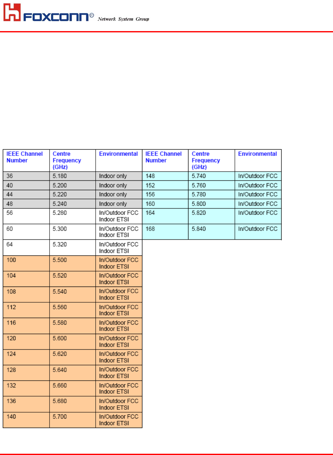
2.1 Operating Frequencies
This section provides the full set of operating frequencies for both IEEE 802.11b/g and IEEE802.11a radios.
Table1. Operating 5GHz frequencies
Page 7 of
15
Version: 0.0
Foxconn Confidential
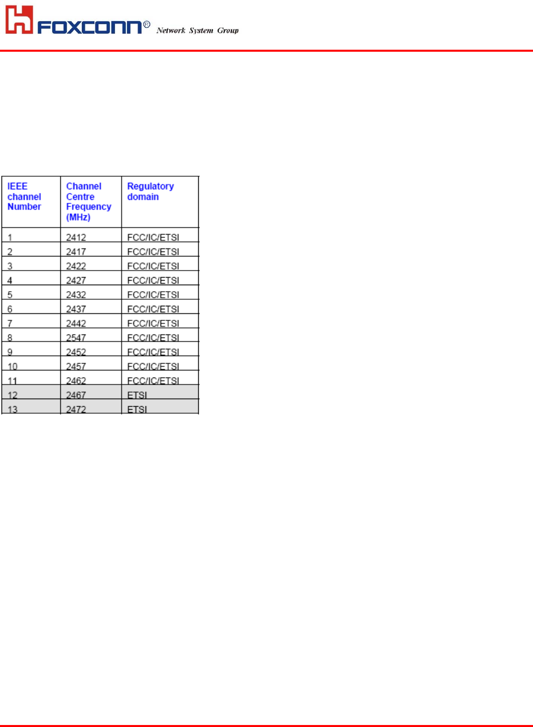
Table2. Operating 2.4GHz frequencies
Page 8 of
15
Version: 0.0
Foxconn Confidential
3 Regulatory Testing Setup and Steps
In order setup the unit for Radio and EMC testing, the followings are required:
‧ Ethernet CAT5 cable (crossover cable if direct connection to AP)
‧ PC
‧ Mounting accessories
‧ External antenna accessories
1) External 5GHz antenna gain: 14dBi
2) The fixed dual band antenna:
Antenna gain for 5GHz: 6.5dBi
Antenna gain for 2.4GHz: 4dBi
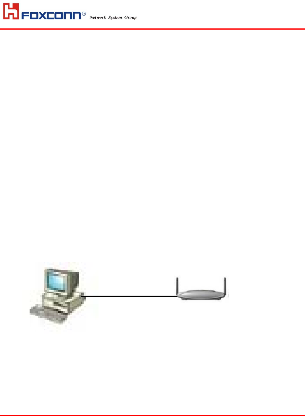
Figure 3 Show the connectivity testing setup.
Figure 3. AP7215 connectivity testing setup.
192.168.10.1
192.168.10.2
CAT5 Ethernet cable

Page 9 of
15
Version: 0.0
Foxconn Confidential
3.1 Instruction to get setup
1) Download the PC_Art.zip file and unzip to your PC's hard drive.
a) For example, unzip to d:\art folder
2) Download the vxWorks-wdb file into your FTP server's home directory.
Configure the FTP server to accept connections based on the following:
a) Username: tl
b) Password: testing
c) Server IP address: 192.168.10.1
d) Filename: vxWorks-wdb
3) Powerup the WARP module and check to see if it downloads the vxWorks-wdb
file from the FTP server. The default IP address on the WARP is 192.168.10.2
4) Create a shortcut on your desktop that points to the art_mb31.bat file found
in the folder where PC_Art.zip was unzipped. Clicking on this shortcut should
start ART communicating with the 11b/g card. Note that the card defaults to
'11g' mode and can be changed by following the instructions on the menu to
toggle the mode.
5) Create another shortcut on your desktop that points to the art_mb23.bat file
found in the folder where PC_Art.zip was unzipped. Clicking on this shortcut
should start ART communicating with the 11a card.
Page 10 of
15
Version: 0.0
Foxconn Confidential
3.2 Instruction to ART function
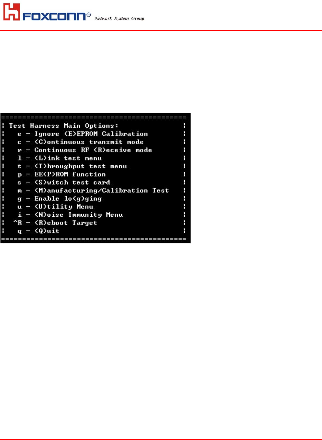
After you getting into ART via art_mb23 (11a card), you can see the image as following :
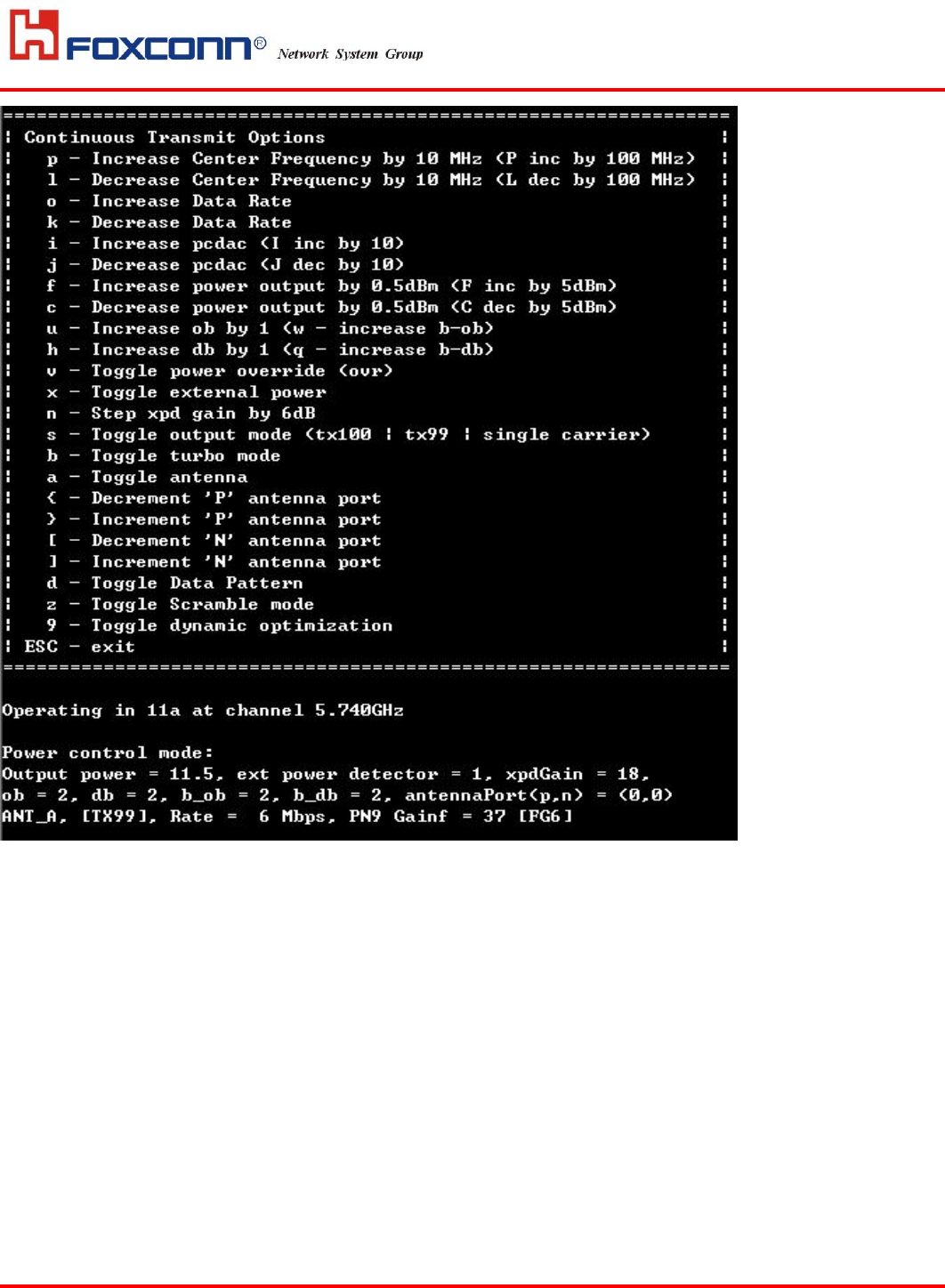
Press “c” to ‘Continuous transmit mode’ , then you can see the image as following :
Page 11 of
15
Version: 0.0
Foxconn Confidential
All the function that ART can be done has shown on the image.
The most basic function and it’s operating parameter are listed as following :
1) Press “P” to increase 5 MHz .
Press “L” to decrease 5 MHz .
Press “Shift + P” to increase 100 MHz .
Press “Shift + L” to decrease 100 MHz .
2) Press “F” to increase output power 0.5 dBm .
Press “C” to decrease output power 0.5 dBm .
Press “Shift + F” to increase output power 5 dBm .
Press “Shift + C” to decrease output power 5 dBm .
3) Press “O” to increase datarate .( 6Mbps to 54Mbps)
Press “K” to decrease datarate . ( 54Mbps to 6Mbps)
4) Press “a” to select the antenna port . (Main or Aux)

Page 12 of
15
Version: 0.0
Foxconn Confidential
5) About the antenna port parameter (p,n) , “p” is the parameter used to control the Main antenna
port and “n” is the parameter used to control the Aux antenna port . The moment when you get
into ‘Continuous transmit mode’, the default setting of (p,n) is (0,0) and the output port is the
internal Main antenna port. Once you change the “p”, the relationship between (p,n) and
antenna port will return to the normal setting . That is when “p(or n)” is 0 and 7, the path is
switched to external antenna port, either Main or Aux. When “p(or n)” is 1 to 6, the path is
switched to internal antenna port. (When you face to the side with 2 antenna port ,Ethernet port and
power supply port of AP7215, the right antenna port is the Main port.)
Press “Shift + { ” to increase “p” .(0~7)
Press “Shift + } ” to decrease “p” .(0~7)
Press “ { ” to increase “n” .(0~7)
Press “ } ” to decrease “n” .(0~7)
After you getting into ART via art_mb22 (11b/g card), all the function and it’s operating parameter are the
same with 11a card, besides the switch of antenna and the change beween 11b or 11g mode.(11b/g card can
only output the power from internal antenna port.) The change between 11b or 11g mode , please press “o”.
Three variation will make a cycle, that is 11g, 11g OFDM and 11b mode.
3.3 Compliance test failure
In case of compliance test failure (not meet required EIRP or emission mask, etc), it is possible
to correct the radio parameters in real-time during regulatory lab testing. In this case, Foxconn technical
person will be on-site to assist in such a case to tuned the required radio parameters and record the profile that
passes the test. The corrected profile will be recorded for subsequent version control issuance of the radio
firmware.
3.4 Regulatory testing priorities
In the spirit of getting quickly the confidence level that the product is aimed at passing all
regulatory rules, the followings shall be tested first:
‧ Test Access Link (2.4GHz) on edge channels (i.e CH1 and CH11 for FCC, CH1 and CH13 for ETSI)
‧ Concentrate initial testing on all edge channels in 5GHz band (FCC: U-NII, ISM, ETSI: 5500-5700MHz)
Page 13 of
15
Version: 0.0
Foxconn Confidential
4 Appendix –A: PC Static IP Configuration
To setup PC running Windows 2000 or up with static IP address configuration (192.168.10.1),
the following steps are required:
‧ Right Click on Start,
‧ Point to “Settings”, “Network and Dial-up Connections”, and Right Click and select
“Open”
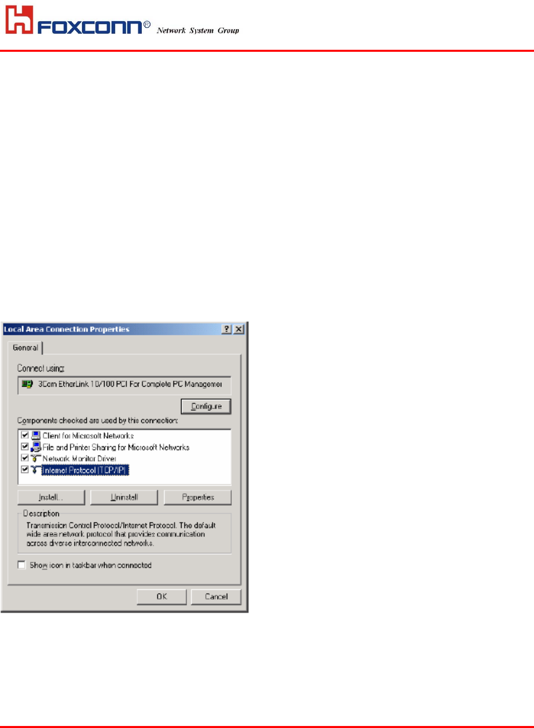
‧ Double Click on the appropriate LAN connection, “Local Area Connection”
‧ Select “Properties”
‧ Double click on “Internet Protocol (TCP/IP)”
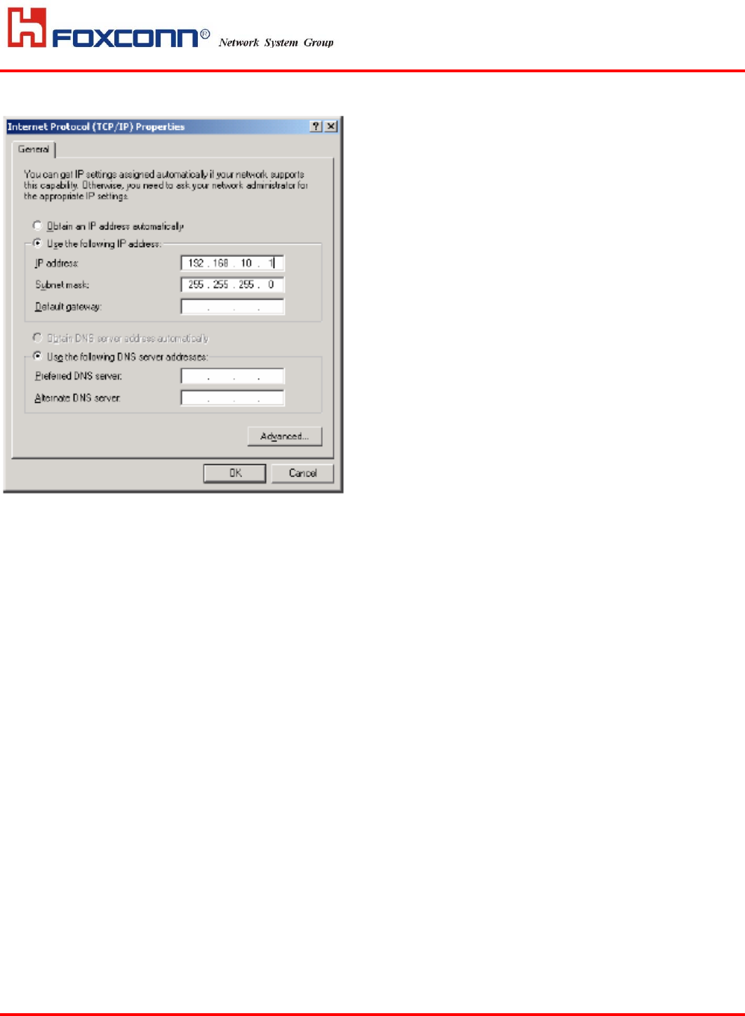
‧ Select “Use the following IP address” and Enter
o 192.168.10.1 for the IP address
o 255.255.255.0 for the Subnet mask
‧ Select “OK “and close down the windows
‧ Select “Use the following IP address” and Enter
o 192.168.10.1 for the IP address
o 255.255.255.0 for the Subnet mask
‧ Select “OK “and close down the windows
Page 14 of
15
Version: 0.0
Foxconn Confidential
‧ Go to Network and Dial-up Connections window
‧ Right click on the Local Area Connection,
‧ Select Disable
‧ Right click on the Local Area Connection,
‧ Select Enable
Page 15 of
15
Version: 0.0
Foxconn Confidential
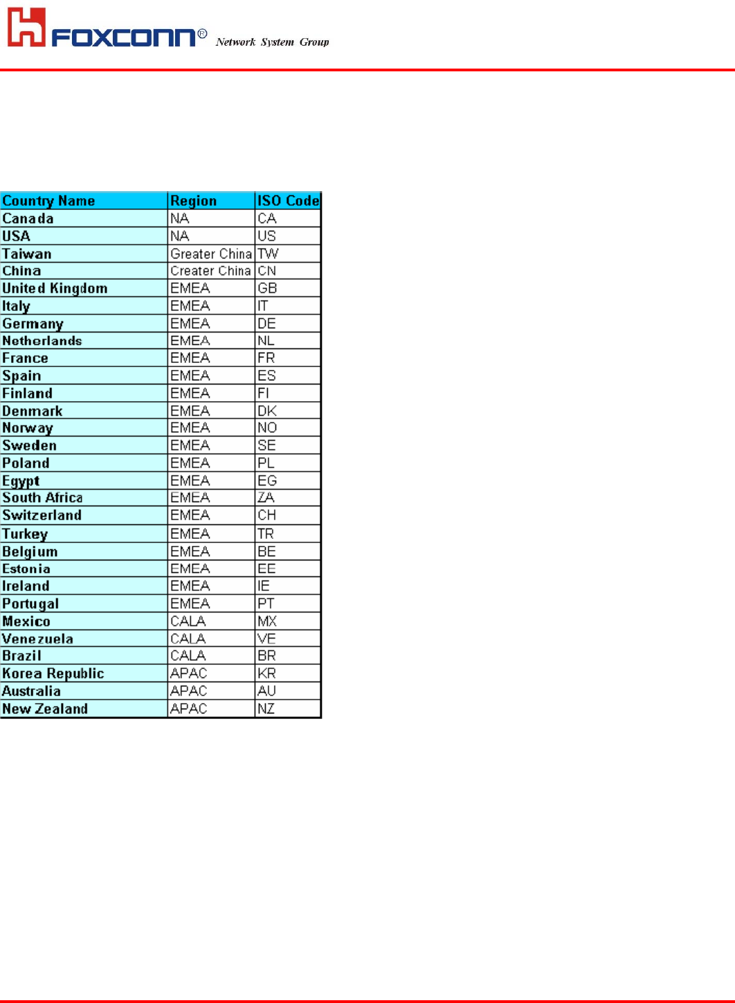
5 Appendix-B: ISO Country Codes
The list below provides the target list of countries for product certification for phase 1 and phase 2 regulatory
testing.