Avaya Canada NTGS09AA 800 MHz CDMA Adjunct System User Manual ation
Avaya Canada Corporation 800 MHz CDMA Adjunct System ation
User Documentation

This document contains Proprietary Information of Northern Telecom Limited. This information is considered to be
CONFIDENTIAL and should be treated appropriately.
EXHIBIT 3
User Documentation
Applicant: Northern Telecom Ltd.
For Type Acceptance/Certification on:
AB6NTGS09AA

This document contains Proprietary Information of Northern Telecom Limited. This information is considered to be
CONFIDENTIAL and should be treated appropriately.
Feasibility Study
During a short feasibility study a number of issues were identified when the CDMA Metrocell is
to be used with the MCPA shelf to deliver maximum 50W of output power per single CDMA
carrier and 100W per two CDMA carriers measured at the MCPA shelf output port. A list of
issues that is provided in this chapter is not complete and more issues are expected to be
identified once design of the project is actively initiated.
Each identified issue has been analyzed and current solutions are provided for each of the issues.
Customer should provide +27V/240 Amps of current for 3 MCPA shelves.
With this power level maximum 3 MCPA shelves will deliver maximum 100W
per sector or 300W per all three sectors. Customer DC power and grounding
strategy should meet Nortel and UL requirements for both CDMA Metrocell
and TDMA radio frame.
Design will specify the MCPA shelf DC power supply requirements and the
customer will be responsible to procure the DC power supply that meets the
specifications. If customer procured DC power supply will not meet the
specified requirements the performance and reliability of the MCPA shelves
could be degraded.
TDMA radio frame is not capable to support more than 2 MCPA shelves.
Either two TDMA radio frames are to be used or additional RIP is to be
installed in the same TDMA radio frame. Furthermore, customer could provide
breakers and power cables for each MCPA shelf in order to limit a number of
TDMA radio frames.
One TDMA radio frame will be limited to support 2 MCPA shelves. One RIP
with 6 breakers, 50W each, will be used for one TDMA radio frame.
CDMA Metrocell customer alarms will require to develop an Alarm Box that
will convert the MCPA shelf alarm logic to the CDMA Metrocell appropriate
alarm logic.
No MCPA shelf alarms will be available with the CDMA Metrocell. The
customer might be able to support the MCPA shelf alarms via the AMPS
equipment, however design is not responsible to either verify or support the
MCPA shelf alarms with the AMPS equipment.
Field calibration procedure will be required to ensure that the MCPA shelf is
set to the correct output power level. The accuracy of the calibration procedure
will be limited by the accuracy of the calibration equipment, MCPA shelf
power detector, CDMA Metrocell HIPD as well as attenuator and cable
absolute loss variation over the operational temperature.
No additional information is available.
CDMA Metrocell system reported transmitted output power will not be correct
as the power level reported by the CDMA Metrocell will be derived based on
the 25W SCPA with reference to the DPM ANT port.
No additional information is available.

This document contains Proprietary Information of Northern Telecom Limited. This information is considered to be
CONFIDENTIAL and should be treated appropriately.
Receiver sensitivity and/or IIP3 will be somewhat impacted if the transmit
signal after the MCPA shelf is to be transmitted via the same DPM that is used
to filter and amplify the receive signal.
No additional information is available.
Receiver sensitivity and/or IIP3 will be impacted for configurations where
CDMA Metrocell receive signals will be shared with AMPS systems,
especially after passing via the AMPS multicouplers.
Excel spreadsheet is available to calculate the CDMA Metrocell degradation
with the AMPS multicouplers in-line.
20 dB 150W power attenuators will require to be mounted in the TDMA radio
frame where sufficient airflow is available for cooling purposes.
It is recommended to mount the fixed attenuators at the back of the MCPA
shelf for modular design and easy accessibility. If thermal or other mechanical
issues will be identified, the fixed attenuators will be mounted below the
MCPA shelves in the TDMA radio frame.
Variable attenuators will require to be mounted in the TDMA radio frame,
possibly in close proximity to the MCPA shelf. In addition, variable attenuators
will have to be easily accessible for calibration purposes in the field.
It is recommended to mount the variable attenuators at the back of the MCPA
shelf for modular design and easy accessibility. If thermal or other mechanical
issues will be identified, the variable attenuators will be mounted below the
MCPA shelves in the TDMA radio frame.
A number of new RF and DC cables will be required to interface the CDMA
Metrocell with the TDMA radio frame and MCPA shelf.
Development will first try to reuse currently designed and available cables from
the CDMA product portfolio.
It is recommended to provision a directional coupler at the output of the MCPA
in order to monitor the output power with the external power meter when the
system is operational as well as during the calibration process. This will ensure
that the cable between the MCPA shelf output and the duplexer will not be
taken off every single time during the calibration.
No additional information is available.
This document contains Proprietary Information of Northern Telecom Limited. This information is considered to be
CONFIDENTIAL and should be treated appropriately.
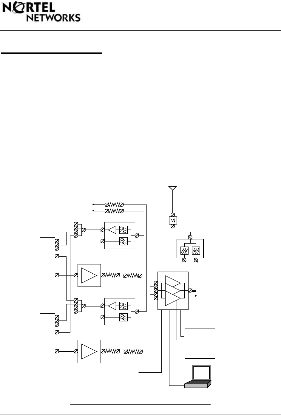
Block Level Diagrams
This chapter provides three high level block diagrams that are given in Figure 1, Figure 2 and
Figure 3 for the 800 MHz CDMA Metrocell that are being examined to provide 100W of RF
power at the MCPA shelf output for 2 CDMA carriers with one or two antennas per sector. In the
first case it was assumed that the CDMA Metrocell and the TDMA radio frame are separated by
some distance and the receive signals for the CDMA Metrocell are provided from AMPS
mupticouplers. In both other cases it was assumed that both CDMA Metrocell and TDMA radio
frame are positioned in close proximity to minimize the Tx loss or the Rx loss between the
CDMA Metrocell and TDMA radio frame.
Development has been requested to support only the configuration that is given in Figure 1 of
this document. The other two configurations have been included for information and will not be
verified as a part of the project. There is some risk that with the configurations that are given in
Figure 2 and Figure 3 receiver sensitivity might be slightly impacted due to the higher Tx noise
level in the receive band or higher power at the receiver front end.
Please note that the information provided in Figure 1, Figure 2 and Figure 3 is generic and intended for
design audience only. This information should not be presented to the customer until it has been approved by
design.
Supported Single Sector 2 Carrier Diagram 1
RS232
+27 V
Return
Ground
50-100 W
20 dB
150 W
Outside
Laptop
Computer
DC POWER
27 V@ 70 AMPS
One Sector
TRM1
RX0
RX1
TX
TRM2
RX0
RX1
TX
PAM2
PAM1
44 dBm
44 dBm
DPM2
DPM2
20 dB
150 W
Field Calibration
50W Carrier
100W Total Power
0 - 5 dB
0 - 5 dB
0.25 dB Tx Cable Loss*
41.2 W Carrier Typical
82.4 W Total Typical
MCPA Alarms
+ 27V - Normal
Open -Alarm
0.6 dB Duplexer Loss
0 - 10 dB
0 - 10 dB
RX1 AMPS
RX0 AMPS
AMPS BTS
This document contains Proprietary Information of Northern Telecom Limited. This information is considered to be
CONFIDENTIAL and should be treated appropriately.
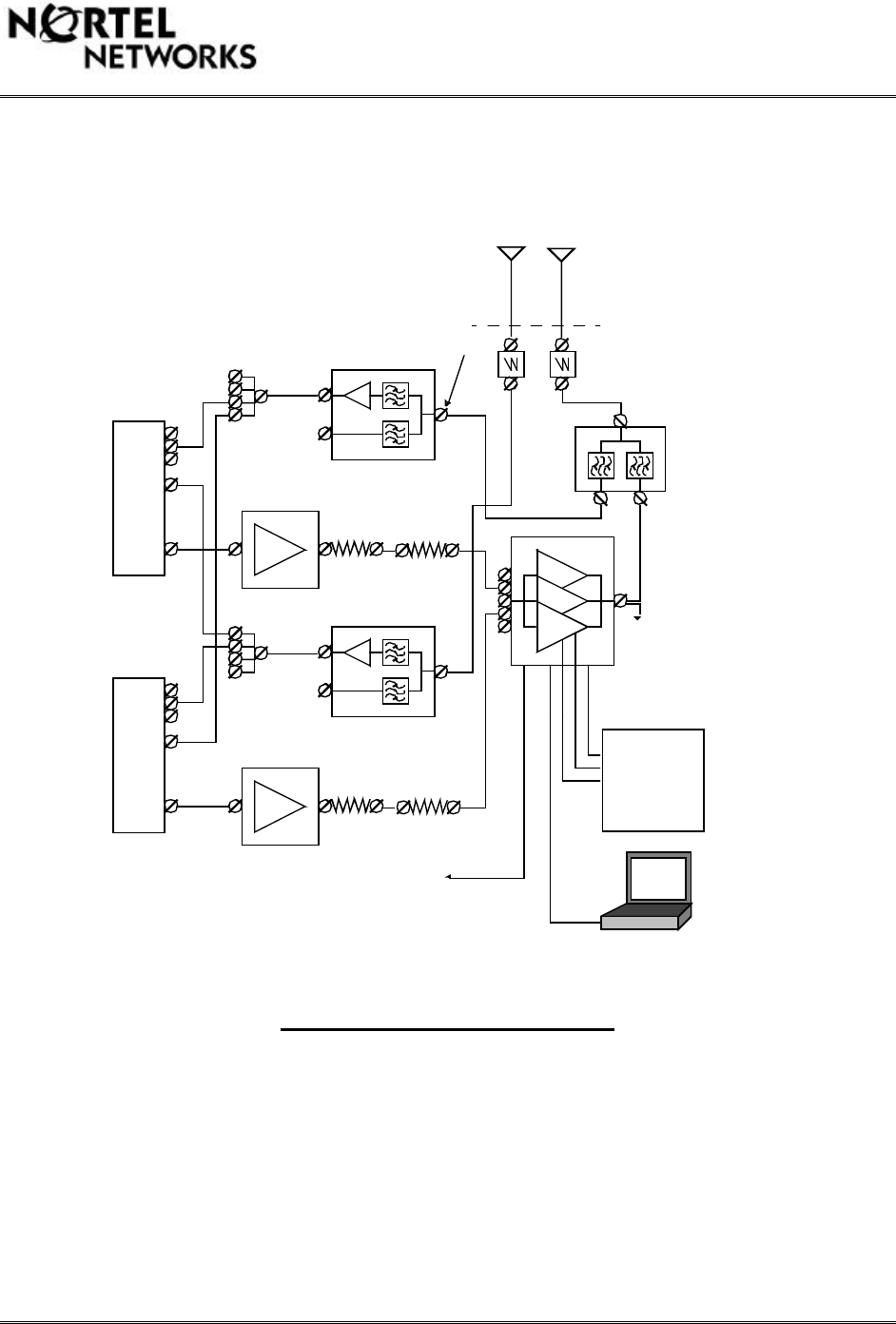
Configurations where main and diversity receive signals are shared with AMPS multicouplers,
especially where the CDMA Metrocell is to receive signals from the AMPS multicouplers, both
receiver noise figure and/or receiver equivalent IIP3 will be degraded for the CDMA Metrocell.
The amount by witch each parameter will be degraded depends on the overall gain, noise figure
and IIP3 of the AMPS multicouplers and cable assembly used to overlay two cellular systems.
Single Sector 2 Carrier Diagram 2
Configuration given in Figure 2 has not been requested by the customer and is not supported by
the development. It has been included into the document for future reference only.
RS232
+27 V
Return
Ground
50-100 W
20 dB
150 W
Outside
Laptop
Computer
DC POWER
27 V@ 70 AMPS
One Sector
TRM1
RX0
RX1
TX
TRM2
RX0
RX1
TX
PAM2
PAM1
44 dBm
44 dBm
DPM2
DPM2
20 dB
150 W
Field Calibration
50W Carrier
100W Total Power
0 - 10 dB
0 - 10 dB
0.25 dB Tx Cable Loss*
41.2 W Carrier Typical
82.4 W Total Typical
MCPA Alarms
+ 27V - Normal
Open -Alarm
0.6 dB Duplexer Loss
0.6 dB Rx Cable Loss*
Rx Sensitivity Impact 1.5 dB
AMPS BTS
This document contains Proprietary Information of Northern Telecom Limited. This information is considered to be
CONFIDENTIAL and should be treated appropriately.
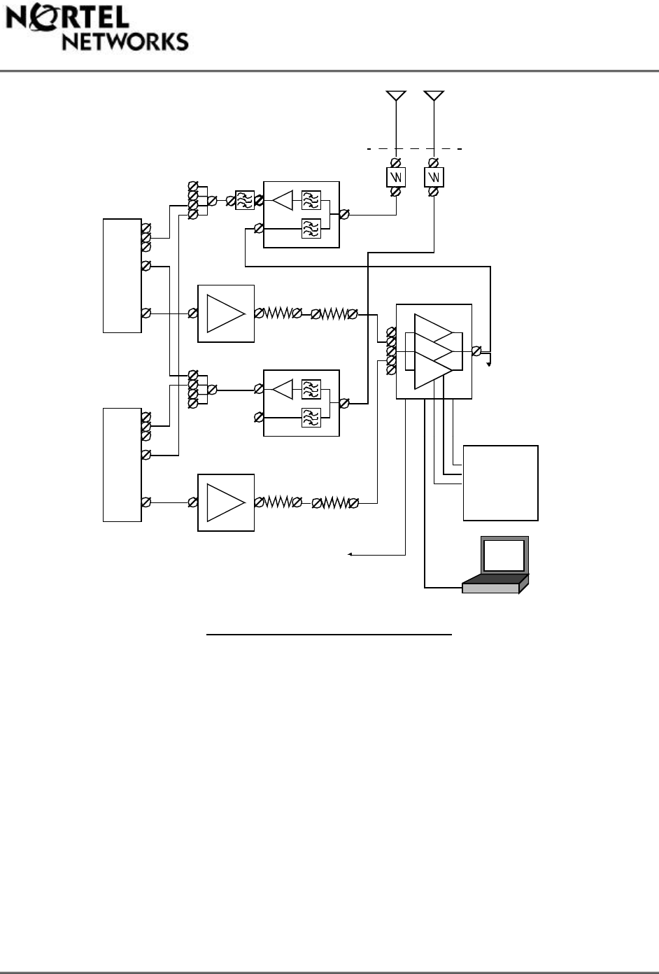
Single Sector 2 Carrier Diagram 3
Configuration given in Figure 3 has not been requested by the customer and is not supported by
the development. It has been included into the document for future reference only.
RS232
+27 V
Return
Ground
50-100 W
20 dB
150 W
Outside
Laptop
Computer
DC POWER
27 V@ 70 AMPS
One Sector
TRM1
RX0
RX1
TX
TRM2
RX0
RX1
TX
PAM2
PAM1
44 dBm
44 dBm
DPM2
DPM2
20 dB
150 W
Field Calibration
50W Carrier
100W Total
Rx Band
0 - 10 dB
0 - 10 dB
0.6 dB Tx Cable Loss*
0.5 dB DPM Loss
38.9 W Carrier Typical
77.8 W Total Typical
MCPA Alarms
+ 27V - Normal
Open -Alarm
AMPS BTS

This document contains Proprietary Information of Northern Telecom Limited. This information is considered to be
CONFIDENTIAL and should be treated appropriately.
System Level Analysis
This chapter provides information that was examined during the initial feasibility and
verification process in order to ensure that TDMA MCPA shelf can be used with the CDMA
Metrocell to deliver higher output power than is currently available with the CDMA Metrocell
25W SCPA.
CDMA System Software
It is the outmost important to ensure that the system software should not be impacted in any way
or the overall system performance should not rely on any changes to the system software.
Configurations that are given in Figure 1, Figure 2 and Figure 3 above should not require any
software changes to be implemented. However, the transmit and receive power levels reported at
the Tx and Rx DPM ANT ports will not be correct until the later system software release is
available.
CDMA Metrocell transmitted power reported by the CDMA Metrocell system software will be
referenced to the DPM ANT port. Future release of system software should have a capability to
enter a loss or gain value to the reported DPM transmitted output power in order to report more
accurately transmitted power level at the CDMA Metrocell demarcation point. Nevertheless, any
additional HPA modules will not be calibrated over the temperature or frequency range, thus the
accuracy of the reported power level will greatly depend on the gain variation of the additional
HPA over the temperature, frequency and input power.
50 W HPA Performance
A single MCPA shelf with 3x50W MCPA units was tested to ensure that it could support 2
CDMA carriers delivering 100 W of RF power at the output of the MCPA shelf without any
additional filtering. The test results demonstrated that at room temperature single MCPA shelf
could deliver, on average, 100 W of RF power while meeting IS-97A specifications of
Conducted Spurious Emissions. However, the receiver band noise was found to be some 10 dB
higher than the specified level for the 800 MHz CDMA Metrocell 25W SCPA. When used with
the CDMA Metrocell DPM, as given in Figure 3, the receiver sensitivity is expected to decrease
by approximately 1.0 dB due to excess of spurious noise in the receiver band.
Tx Input and Output Power Levels
The output power of the CDMA Metrocell PAM should not be changed in any way. In addition,
all global parameters of the CDMA Metrocell should not be altered in any way to support MCPA
shelf in conjunction with the CDMA Metrocell PAM. In addition, any change to the CDMA
Metrocell global parameters after the MCPA shelf have been calibrated might result in
overdriving the MCPA shelf, possible damage to the MCPA shelf as well as new calibration to
be performed.
A single MCPA shelf with 3x50W MCPA units is expected to meet the following power
requirements that are given in Table 5.

This document contains Proprietary Information of Northern Telecom Limited. This information is considered to be
CONFIDENTIAL and should be treated appropriately.
Description Specification Units
Minimum Input Power per Carrier 10 dBm
Minimum Total Input Power 13 dBm
Maximum Input Power per Carrier 20 dBm
Maximum Total Input Power 23 dBm
Maximum Output Power per
Carrier 47 dBm
Maximum Total Output Power 50 dBm
Typical Output Power Accuracy +/- 0.75 dB
MCPA Power Requirements
Receiver Performance
Receiver performance is expected to meet all IS-97A requirements but slightly degrade over the
800 MHz CDMA Metrocell base product performance. This is applicable for configurations that
are given in Figure 1 and Figure 3 of this document. In Figure 1 receiver noise figure and/or
IIP3 will be impacted to some extend depending on the AMPS multicoupler performance. In
Figure 3 receiver noise and/or IIP3 might be impacted due to the higher spurious noise level in
the receiver band and higher power level in the transmit band.
IS-97A Performance
It is expected that the CDMA Metrocell with the MCPA shelf delivering maximum of 100W of
RF power at the MCPA shelf output with 2 CDMA carriers should meet all IS-97A
requirements. Nevertheless, the performance of the CDMA Metrocell with the MCPA shelf
delivering maximum power level will somewhat degrade when compared with the 800 MHz
CDMA Metrocell base product.
MCPA Alarm Specification
No MCPA shelf alarms will be supported by the CDMA Metrocell. The initial requirement to
support the MCPA shelf alarms has been removed due to time and cost constrains of the project.
Customer Power Supply and Grounding
DC power supply and grounding will be provided separately for each TDMA radio frame. This
information is the outmost important and should be available to ensure that MCPA shelf could be
safely powered up, deliver the appropriate amount of RF power and did not degraded the quality
of the CDMA transmit signal and the overall performance of the CDMA Metrocell. At the
present time Nortel PLM has informed design that the Nortel customer will supply the DC power
that is in agreement with the MCPA shelf specification. Should this not be the case the design
will inform the design customer, Nortel CDMA PLM group, that a different power supply should
be used by the Nortel customer to guarantee the performance of the MCPA shelf, safety of the
This document contains Proprietary Information of Northern Telecom Limited. This information is considered to be
CONFIDENTIAL and should be treated appropriately.
field personnel, quality of the CDMA transmit signal or the overall performance of the CDMA
Metrocell.
MCPA Field Calibration
There will be a new requirement to perform field calibration of the MCPA shelf in order to
guarantee the output power of the MCPA shelf within some degree of accuracy. It is expected
that after calibration has been performed and the power levels have been verified the MCPA
shelf could be powered down without the need to recalibrate the MCPA shelf when they are
powered back up. However, this will be the case only if the input power to the MCPA shelf will
not changed. In other words, the calibration of the MCPA shelf should guarantee only the gain
setting, and not the output power. Should the input signal to the MCPA shelf change after it has
been calibrated, the output power of the MCPA shelf will also change. The accuracy of the
calibration procedure will greatly depend on the MCPA shelf power estimation accuracy, field
calibration equipment accuracy and the CDMA Metrocell power estimation accuracy. Based on
the above factors and currently available information it is reasonable to assume that after MCPA
shelf has been calibrated the output power level of the MCPA shelf should be within 1.5 dB of
its target value (+/-0.75 dB).
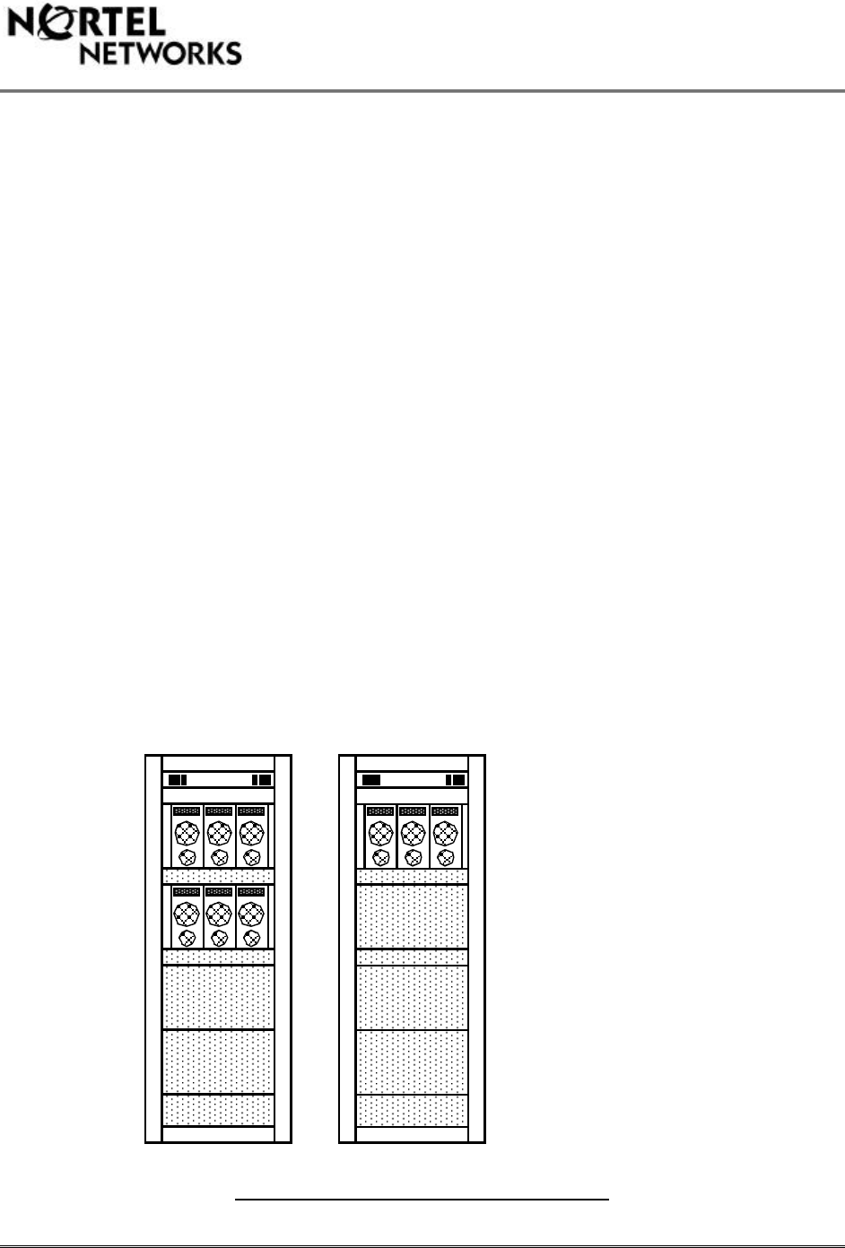
TDMA Radio Frame Assembly
Currently TDMA radio frame supports maximum 2 MCPA shelves. Although there is room
available to position an additional MCPA shelf with 3x50W MCPA units, a single RIP is
designed to power up maximum 2 MCPA shelves.
In order to support 2 carrier 3 sector CDMA Metrocell with 50W per carrier two TDMA radio
frames are required. One TDMA radio frame should have 2 MCPA shelves whereas the second
TDMA radio frame should have 1 MCPA shelf. Three sector two carrier TDMA radio frames are
given in Figure 4.
TDMA Two Radio Frame Configuration
RIP
Additional Equipment
- Attenuator Bracket
Duplexer Shelf RIP
Duplexer Shelf
20 dB 150W Fixed
10 dB Variable
2 carrier 2 sector view
2 carrier 1 sector view

This document contains Proprietary Information of Northern Telecom Limited. This information is considered to be
CONFIDENTIAL and should be treated appropriately.
The Attenuator Shelf might be eliminated if it will be possible to mount fixed and variable
attenuators at the back of the MCPA shelf. This would allow to minimize mechanical work
required and allow to provision a set of attenuators per each MCPA shelf. However, this solution
must be further investigated to ensure that the MCPA shelf cooling will not be hampered as well
as the attenuators will not change its characteristics because of the MCPA shelf heat dissipation.
Field Assembly and Installation
Although this project is developed to operate with the 800 MHz CDMA Metrocell, TDMA radio
frames will be procured by the Nortel customer separately from the 800 MHz CDMA Metrocell.
Furthermore, the attenuator bracket with fixed and variable attenuators as well as the interface
cables will also be ordered separately by the customer. The attenuator bracket will be assembled
in the field and interfaced with the MCPA shelf and the CDMA Metrocell following instructions.
This document contains Proprietary Information of Northern Telecom Limited. This information is considered to be
CONFIDENTIAL and should be treated appropriately.
Power Supply and Grounding
MCPA DC Power Supply
This chapter provides specifications for the TDMA radio frame and MCPA shelf DC
power supply. The Nortel customer is responsible to provision a DC power supply that
meets a set of requirements specified in Table 6 and Table 7.
Each TDMA radio frame is capable to support 2 MCPA shelves or 6 50W MCPA units.
The DC power supply is specified for one TDMA radio frame with 2 MCPA shelves. The
output power per carrier should be limited to 50 W. The output power per TDMA radio
frame should be limited to 200 W for a two carrier two sector configuration.
MCPA shelf DC power supply specification for single TDMA radio frame is given in
Table 6.
#Description Specification Units Comments
1Nominal Operational Voltage 27.00 VDC
2Minimum Operational Voltage 21.00 VDC
3Maximum Operational Voltage 30.00 VDC
4Maximum Length of Stranded
2/0 AWG Power Feed at 30 oC 4.6 mDistance from the
power plant
charge bar to the
RIP
5Maximum Power Plant Voltage
Drop 0.25 VDC
6Maximum Feed/Return Voltage
Drop 0.25/0.25 VDC
7Total RF Frame Current Draw 180 ADC 2 MCPA shelves
8Minimum Voltage for Full Power 24 VDC
9Absolute Maximum Voltage 30.5 VDC No Damage,
applied
continuously
10 Transient Voltage Immunity for
3 ms 50 V
11 TSP Shelf Inrush Current at
Nominal Voltage
- Over 0.3 ms
31 ADC
12 MCPA Inrush Current at
Nominal Voltage
- Over 0.2 ms
- Over 0.5 ms
- Over 1.8 ms
- Over 700 ms
470
470
380
70
ADC
ADC
ADC
ADC

This document contains Proprietary Information of Northern Telecom Limited. This information is considered to be
CONFIDENTIAL and should be treated appropriately.
13 DC Power Noise Conducted
Immunity
- Voice Frequency Noise Level
- Radio Frequency Noise Level
in any 3 kHz Band
from 10 kHz to 20 MHz
- Broadband Noise Level
56
100
300
dBrnc
mVrms
mVp-p
14 DC Power Noise Conducted
Emissions
- Voice Frequency Noise Level
- Radio Frequency Noise Level
- Broadband Noise Level
9+10*log(IDC
)
(IDC)1/2
250
dBrnc
mVrms
mVp-p
15 Supply Voltage Step +/-3 VDC Within nominal
operating range
with 1V/ms
maximum rate
Two Carrier Two Sector MCPA DC Power Supply Specification
TDMA radio frame power consumption and current draw are given in Table 7 for configurations
with 1 MCPA shelf and 2 MCPA shelves. The power consumption is specified with the Nominal
Voltage.
#Description Maximu
m
Current
(ADC)
Nominal
Current
(ADC)
Maximu
m Power
(kW)
Nominal
Power
(kW)
11 MCPA Shelf Feed A TBD TBD TBD TBD
1 MCPA Shelf Feed B TBD TBD TBD TBD
1 MCPA Shelf Total TBD TBD TBD TBD
22 MCPA Shelves Feed
ATBD TBD TBD TBD
2 MCPA Shelves Feed
BTBD TBD TBD TBD
2 MCPA Shelves Total TBD TBD TBD TBD
TDMA Radio Frame Power Consumption

This document contains Proprietary Information of Northern Telecom Limited. This information is considered to be
CONFIDENTIAL and should be treated appropriately.
TDMA Radio Frame Grounding
North American electrical codes require that there is no current over the grounding conductors
(C22.1 part 10-200 and ANSI/NFPA Number 70 article 250-21) and the safety standard specify
that electrical codes be adhered to. Therefore, each cell site has to be inspected by the safety
authority (UL/CSA approval in North America) such code requirements (refer to UL 1950, third
edition/CAN/CSA C22.2 Number 950-M95) are met in order to obtain an approval from that
authority. Site installation and power up are subject to NEC and CEC and local codes.

This document contains Proprietary Information of Northern Telecom Limited. This information is considered to be
CONFIDENTIAL and should be treated appropriately.
MCPA Field Calibration
General Information
This chapter will provide detail information on how to perform the calibration of the MCPA
shelf in the field in order to achieve 50 W per single CDMA carrier or 100 W per two CDMA
carriers at the output of the MCPA shelf. It is the outmost important to ensure that all equipment
is calibrated and all measurement are performed as described in this chapter in order to ensure
that the output power of the MCPA shelf is fairly accurate and close to the calibrated output
power level.
In order to ensure that the maximum MCPA shelf output power is as close as possible to 50W
per CDMA carrier it is recommended to set the CDMA Metrocell to transmit maximum output
power during the calibration procedure. If it is not possible to set the CDMA Metrocell to
transmit the maximum output power during the calibration procedure, current calibration
procedure will change.
Calibration Procedure
Set the CDMA Metrocell to output maximum power 42.72 dBm at the DPM
ANT port. This power level should be verified with a power meter and
confirmed with the CDMA Metrocell reported maximum Tx power level.
CDMA Metrocell should be configured to generate the forward waveform with
the Overhead Channels and 6 OCNS channels.
Adjust the variable attenuator until the power meter is reading +13 +/- 0.05
dBm.
Connect the input signal to one of 5 available MCPA input ports.
Connect a calibrated 20 dB/150 W attenuator with a short cable to the MCPA
output.
Connect the power meter with a thermal sensor to a calibrated 20dB/150W
attenuator.
Set the power meter Offset to the measured loss of the 20dB/150W attenuator
with a short cable.
Connect a computer with the MCPA shelf with the RS232 cable.
Start Nortel Calibration Software and set Target Power to 50 W and Number of
Channels to 1.
Start Calibration of the MCPA.
Ensure the power level measured with the power meter and power level
reported by Nortel Calibration Software are accurate within 0.1 dB. It is
important to remember that the power meter measurement should always be
considered more accurate than the power level reported by the calibration
software.

This document contains Proprietary Information of Northern Telecom Limited. This information is considered to be
CONFIDENTIAL and should be treated appropriately.
Leave the CDMA Metrocell and MCPA shelf transmitting maximum power for
at least 2 hours.
Verify the calibration accuracy after 2 hours by measuring the MCPA output
power with a power meter.
If the output power has change from previously calibrated 50W, verify if the
Metrocell output power level has changed from the previously recorded power
level.
If the Metrocell output power has not changed by the same amount in dB as the
MCPA output power level has changed, repeat the calibration procedure from
the beginning by adjusting the Metrocell output power to its maximum power
level.
This document contains Proprietary Information of Northern Telecom Limited. This information is considered to be
CONFIDENTIAL and should be treated appropriately.
Provisioning Guide
Preferred CDMA Channels
800 MHz Metrocell product is designed to operated over the entire cellular frequency band.
However, due to the licence agreements most customers are limited to operate in either A&AÓ
or B&BÕ cellular bands. In both A and B cellular bands it is recommended to use the Primary
channels as the first CDMA channels for roaming and service availability. This practice is
currently used by most Nortel customers. Based on the Primary channels initial deployment it is
recommended to introduce additional channels 42 AMPS channels apart or 1.26 MHz. This is
important as the IMF and the Combiner are developed for a channel to channel separation of 42
AMPS channels or 1.26 MHz. The list of preferred CDMA channels for the cellular band is
given in Table 8.
#Channel Rx Frequency
(MHz) Tx Frequency
(MHz) Channel
Deployment Comment
1 31 825.93 870.93 7A Band
2 73 827.19 872.19 6A Band
3 115 828.45 873.45 5A Band
4 157 829.71 874.71 4A Band
5 199 830.97 875.97 3A Band
6 241 832.23 877.23 2A Band
7283 833.49 878.49 1Primary A Band
8384 836.52 881.52 1Primary B Band
9 426 837.78 882.78 2B Band
10 468 839.04 884.04 3B Band
11 510 840.30 885.30 4B Band
12 552 841.56 886.56 5B Band
13 594 842.82 887.82 6B Band
14 758 847.74 892.74 7BÕ Band
Preferred Cellular Band Channels
Please note that channel 758 might not meet the out of band spurious emissions, thus this
channel might not be supported. This information is to be verified during the System Verification
process.
Provisioning Guide
This chapter provides generic provisioning guide for Nortel customers to follow while ordering
TDMA equipment to support 50W per CDMA carrier. Please note that Table 9 does not contain
detail information of the additional equipment required to support 50W per CDMA carrier. The
detail information will be provided at a later date after the initial prototype unit has been
assembled and functionally verified.
This document contains Proprietary Information of Northern Telecom Limited. This information is considered to be
CONFIDENTIAL and should be treated appropriately.
#Equipment 1
Carri
er
1
Secto
r
1
Carri
er
2
Secto
r
1
Carri
er
3
Secto
r
2
Carri
er
1
Secto
r
2
Carri
er
2
Secto
r
2
Carri
er
3
Secto
r
1TDMA Radio Frames 1 1 2 1 1 2
2RIP 1 1 2 1 1 2
3Duplexer Shelf 1 1 2 1 1 2
425 MHz Duplexer Unit 1 2 3 1 2 3
5MCPA Shelf 1 2 3 1 2 3
650W MCPA Unit 2 4 6 3 6 9
7Attenuator Bracket 1 2 3 1 2 3
820dB 150W Attenuator 1 2 3 2 4 6
920 dB Variable Attenuator 1 2 3 2 4 6
10 Directional Coupler 1 2 3 1 2 3
11 Variable to Fixed Attenuator
Cable 1 2 3 2 4 6
12 Variable Attenuator to MCPA
Cable 1 2 3 2 4 6
13 MCPA to Duplexer Cable 1 2 3 1 2 3
14 Field Assembled Metrocell to
Fixed Attenuator Cable 1 2 3 1 2 3
15

This document contains Proprietary Information of Northern Telecom Limited. This information is considered to be
CONFIDENTIAL and should be treated appropriately.
System Verification
It is planned to perform system level verification first at room temperature in the RF Lab and
then repeat the same verification over the temperature in the Temperature Chamber to record any
deviation over the room temperature. The actual test time will take little time in comparison with
the set up time for different conditions.
The following set of tests are planned to be performed at room temperature first. The same test
will be repeated over the operational temperature range with the TDMA radio frame as well as
fixed and variable attenuators positioned in the temperature chamber. Please note that the
Metrocell will not be placed in the temperature chamber and will always be operational at room
temperature only. If required, the Metrocell performance over the operational temperature range
might be analyze to derive any degradation over the temperature if both systems, CDMA
Metrocell and the TDMA radio frame with the MCPA shelf were to be exposed to temperature
variation. The TDMA radio frame with the MCPA shelf will be tested at Minimum and
Maximum temperature.
MCPA Calibration and Gain Variation for Single Carrier
Set the Metrocell to transmit Overhead and 6 OCNS channels.
Adjust the Metrocell to transmit the maximum output power.
Adjust the MCPA DC power supply voltage to +27 V.
Adjust a single CDMA carrier to output +13 dBm at the MCPA input.
Calibrate the MCPA to generate 47 dBm at the MCPA output.
Measure and record the output power over a 2 hour time period.
Change the MCPA DC power supply voltage to +24 V.
Measure and record the output power.
Change the MCPA DC power supply voltage to +29.5 V.
Measure and record the output power.
Repeat the same procedure for +24 V and +29.5 V.
MCPA Calibration and Gain Variation for Two Carriers
Set the Metrocell to transmit Overhead and 6 OCNS channels.
Adjust the Metrocell to transmit the maximum output power.
Adjust the MCPA DC power supply voltage to +27 V.
Adjust each CDMA carrier to output +13 dBm at the MCPA input.
Calibrate the MCPA to generate 50 dBm at the MCPA output.
Measure and record the output power over a 2 hour time period.
Change the MCPA DC power supply voltage to +24 V.
Measure and record the output power.

This document contains Proprietary Information of Northern Telecom Limited. This information is considered to be
CONFIDENTIAL and should be treated appropriately.
Change the MCPA DC power supply voltage to +29.5 V.
Measure and record the output power.
Repeat the same procedure for +24 V and +29.5 V.
MCPA Spurious Emissions and Code Domain Noise
Set the Metrocell to transmit Overhead and 6 OCNS channels.
Adjust the Metrocell to transmit the maximum output power.
Adjust the MCPA DC power supply voltage to +27 V.
Adjust single CDMA carrier to output +13 dBm at the MCPA input.
Calibrate the MCPA to generate 47 dBm at the MCPA output.
Measure and record MCPA conducted spurious emissions.
Measure and record Code Domain Noise.
Change the MCPA DC power supply voltage to +24 V.
Measure and record MCPA conducted spurious emissions.
Measure and record Code Domain Noise.
Change the MCPA DC power supply voltage to +29.5 V.
Measure and record MCPA conducted spurious emissions.
Measure and record Code Domain Noise.
Change the MCPA DC power supply voltage to +27 V.
Adjust second CDMA carrier to output +13 dBm at the MCPA input.
Calibrate the MCPA to generate 50 dBm at the MCPA output.
Measure and record MCPA conducted spurious emissions.
Measure and record Code Domain Noise.
Change the MCPA DC power supply voltage to +24 V.
Measure and record MCPA conducted spurious emissions.
Measure and record Code Domain Noise.
Change the MCPA DC power supply voltage to +29.5 V.
Measure and record MCPA conducted spurious emissions.
Measure and record Code Domain Noise.
MCPA Waveform Quality and Time Accuracy
Set the Metrocell to transmit Pilot Channel only.
Adjust the Metrocell to transmit approximately +36 dBm.
Adjust the MCPA DC power supply voltage to +27 V.

This document contains Proprietary Information of Northern Telecom Limited. This information is considered to be
CONFIDENTIAL and should be treated appropriately.
Adjust each CDMA carrier to output +13 dBm at the MCPA input.
Calibrate the MCPA to generate 50 dBm at the MCPA output.
Measure and record Waveform Quality for each carrier.
Measure and record Time Accuracy for each carrier.
Change the MCPA DC power supply voltage to +24 V.
Measure and record Waveform Quality for each carrier.
Measure and record Time Accuracy for each carrier.
Change the MCPA DC power supply voltage to +29.5 V.
Measure and record Waveform Quality for each carrier.
Measure and record Time Accuracy for each carrier.
This document contains Proprietary Information of Northern Telecom Limited. This information is considered to be
CONFIDENTIAL and should be treated appropriately.
Installation Method
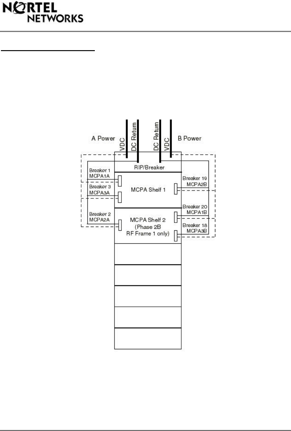
TDMA Frame Power Distribution
The TDMA frame is powered by two 27 VDC power feeds (A&B). The power feeds are routed
through the top panel of the RIP at the top of the TDMA frame. Power is distributed to each
MCPA shelf as shown in Figure 5.
Figure 5: TDMA Frame DC Power Distribution
This document contains Proprietary Information of Northern Telecom Limited. This information is considered to be
CONFIDENTIAL and should be treated appropriately.
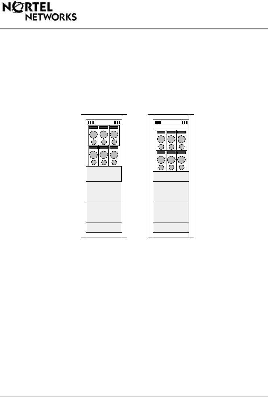
TDMA Frame Configuration
The TDMA frame (NTFC01AE) will come configured with space and cabling for two MCPA
shelves. The MCPA shelves will come positioned at the top of the TDMA frame as shown in
Figure #6, config #1. The duplexer shelf does not come standard with the TDMA frame
therefore one must be ordered separately (see section 8.5 - TDMA Equipment List). It is
necessary to lower the MCPA shelves such that the duplexer shelf can be positioned above the
MCPA shelves (config #2 in Figure 6). Alternatively the duplexer shelf could be mounted below
the MCPA shelves, but it is recommended to install the duplexer shelf above the MCPA shelves
to ensure all interconnect cables will reach.
Figure 7: TDMA Frame
RIP RIP
Duplexer Shelf
(Frame without Duplexers) (Frame With Duplexers)
config #1 config #2
NTFC01AE NTFC01AE (modified)
This document contains Proprietary Information of Northern Telecom Limited. This information is considered to be
CONFIDENTIAL and should be treated appropriately.
In order for the duplexer shelf to be mounted above the MCPA shelves, the MCPA shelves and
associated support brackets should be lowered by the height of the duplexer shelf of 2U
(1U=1.75”). It is also necessary to remove two support brackets from an empty radio shelf
location and re-install them at the duplexer location to support the duplexer shelf.
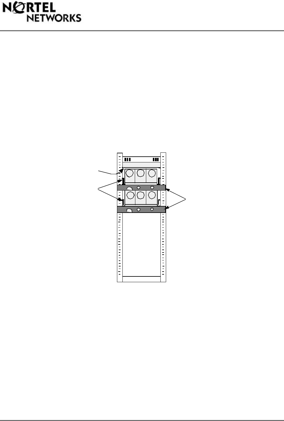
Figure #7 shows a rear view of the TDMA frame with all support brackets in the correct location.
The TDMA frame has markers on the left side of the frame that are spaced by 1U. Every tenth
marker is labelled with a number. Numbering starts at the bottom of the frame. Figure #10
shows a more detailed diagram of the exact location of each attenuator bracket on the TDMA
frame. It is important to mount all shelf support brackets in the proper location as they will
determine the position of the duplexer shelf and MCPA shelves, which will determine the
position of the attenuator brackets.
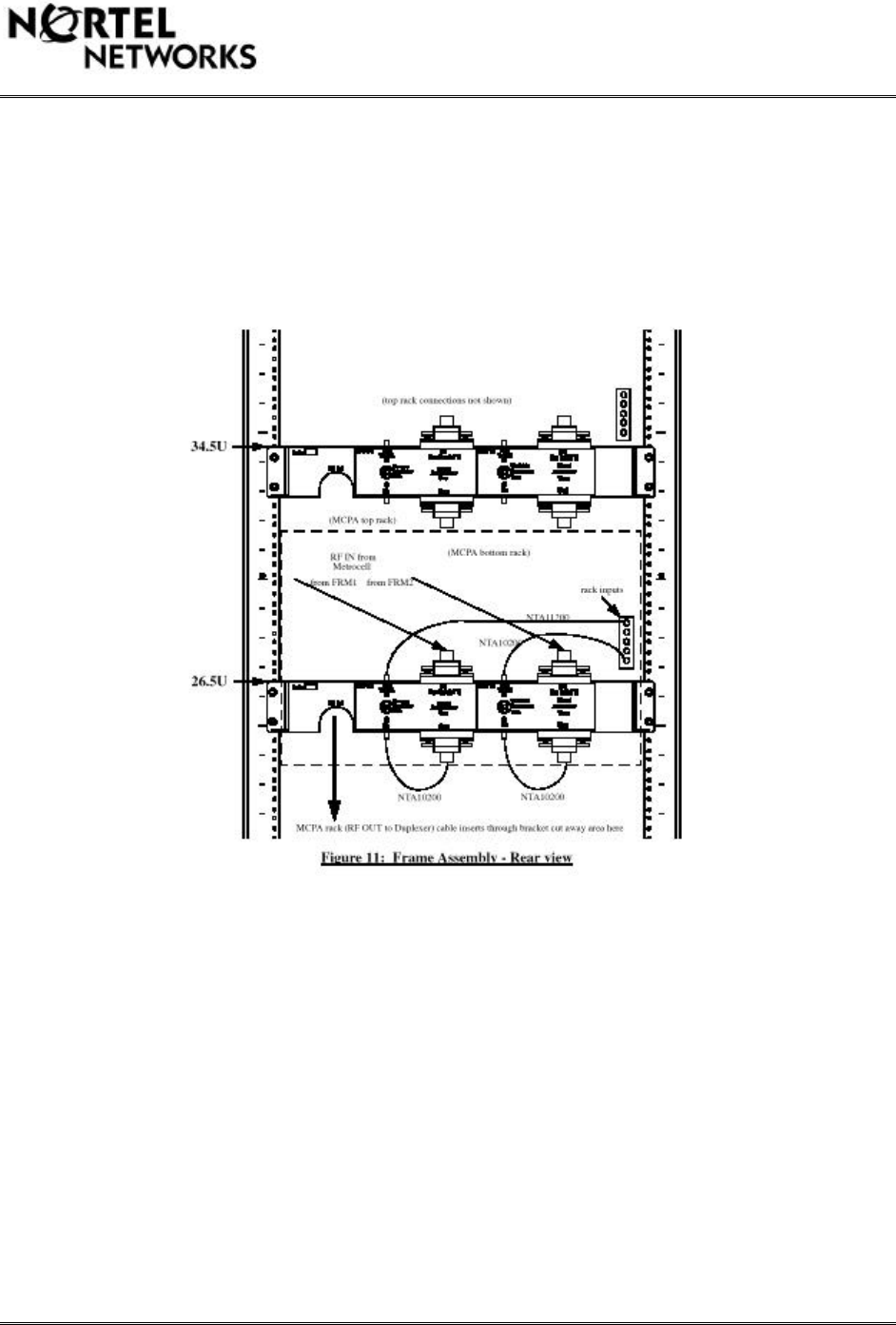
Figure 8: TDMA Frame Rear View
The duplexer support brackets are located such that the bottom of the brackets are in line with
the marker indicating 40U. The support brackets for the top MCPA shelf are located such that
the bottom of the brackets are in line with the marker corresponding to 34U. The support
brackets for the bottom MCPA shelf are located such that the bottom of the brackets are in line
with the marker corresponding to 26U
Rip
40
30
20
10
MCPA
Duplexer
MCPA
MCPA
MCPA
MCPA
MCPA
MCPA Shelf
Support Brackets
Duplexer Support Bracket
Attenuator Brackets
This document contains Proprietary Information of Northern Telecom Limited. This information is considered to be
CONFIDENTIAL and should be treated appropriately.
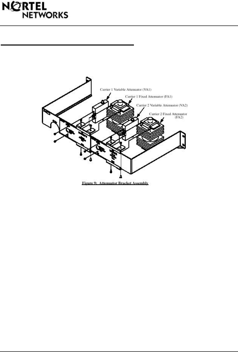
Attenuator Bracket Configuration
Figure #8 shows an exploded view of how the attenuators should be mounted on the bracket:
The variable attenuators are bidirectional. Turning the screw in the counter-clockwise direction
will increase attenuation. These attenuators will typically come from the manufacturer with the
screw set for minimum attenuation.
The fixed attenuators are not bidirectional, so care should be taken to ensure the proper
orientation of the input and output ports before fastening to the bracket. The input port should
face towards the top of the frame, and the output port should face the ground.
The following figure shows a high level view of the attenuator bracket locations on the TDMA
frame (MCPA shelves not shown):
This document contains Proprietary Information of Northern Telecom Limited. This information is considered to be
CONFIDENTIAL and should be treated appropriately.
This document contains Proprietary Information of Northern Telecom Limited. This information is considered to be
CONFIDENTIAL and should be treated appropriately.
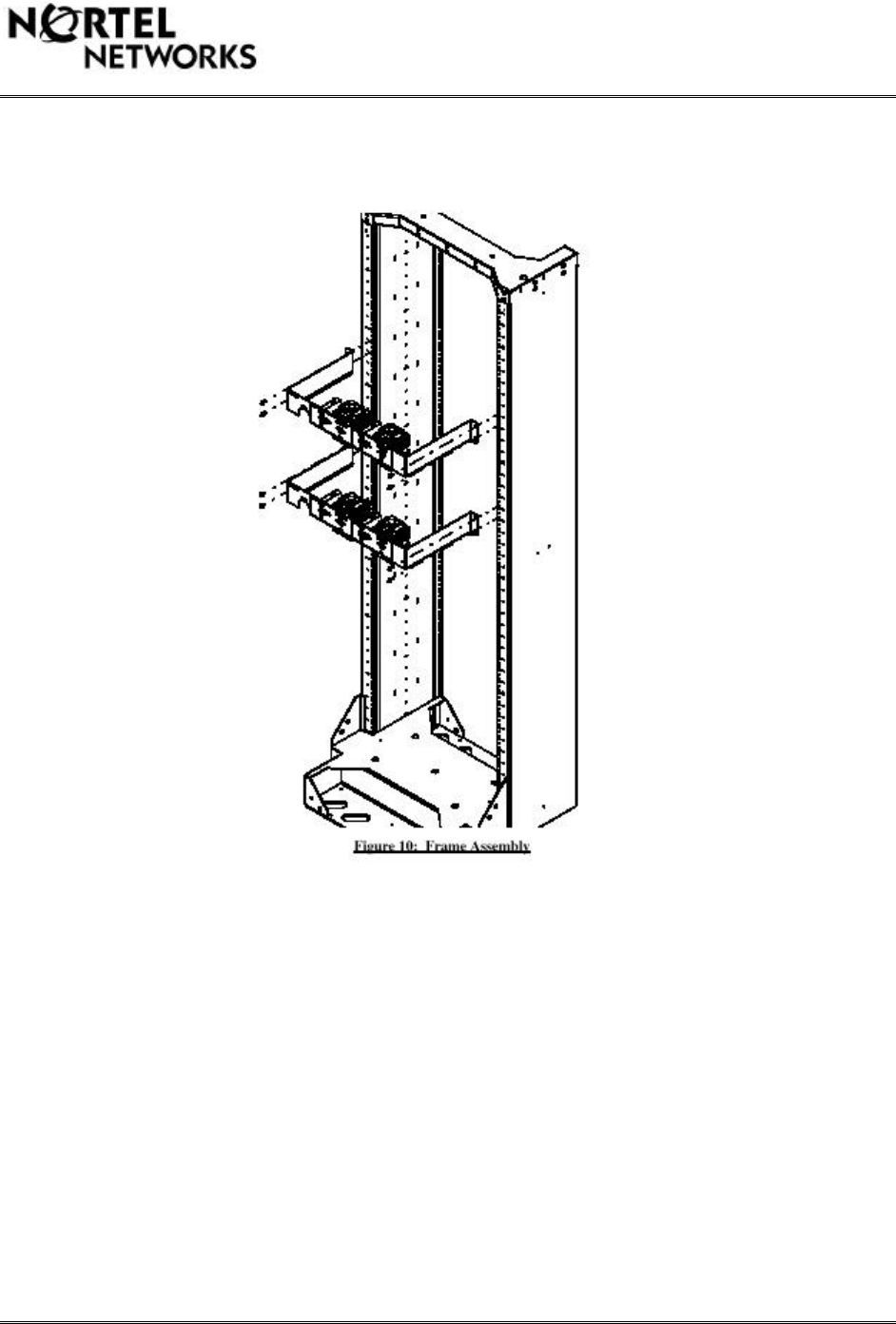
The attenuator brackets should be mounted on the rear of the TDMA frame such that they are positioned
directly behind the MCPA shelves allowing for the MCPA RF output cable to be routed through the cut away
area in the brackets. The mounting ("U") locations for each bracket are shown below (referenced to top edge of
attenuator bracket):
The above recommended "U" locations for the attenuator brackets assume the duplexer shelf was mounted at
40U, the top MCPA shelf was mounted at 34U and the bottom MCPA shelf was mounted at 26U (see Figure
7).
If these recommended positions are not followed, the installer must at least ensure the attenuator bracket is
mounted such that it allows clearance for the MCPA rack RF OUTPUT cable.
This document contains Proprietary Information of Northern Telecom Limited. This information is considered to be
CONFIDENTIAL and should be treated appropriately.
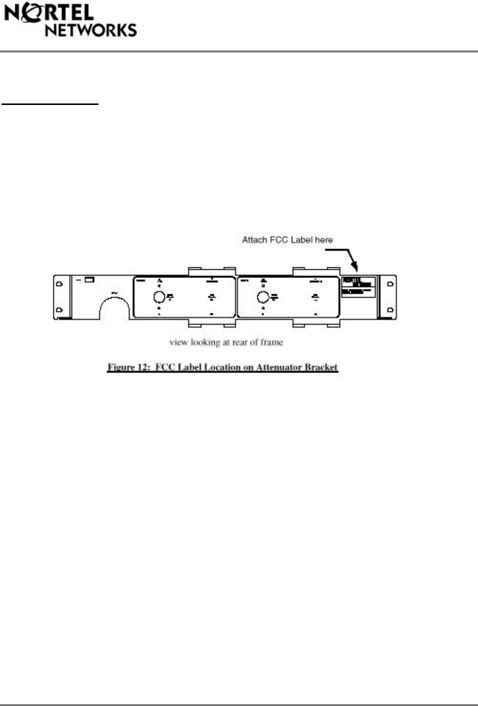
FCC labelling
The following figure shows the location where the FCC identification label must be affixed:
This document contains Proprietary Information of Northern Telecom Limited. This information is considered to be
CONFIDENTIAL and should be treated appropriately.
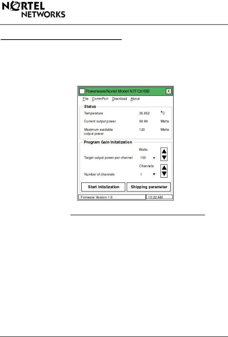
TDMA PA Calibration Software
Calibration of the TDMA system output power must be accomplished via an RS-232 interface to
the back of each MCPA rack connector “J6”. Each rack (or sector) must be calibrated
individually. The MCPA shelf interface software (NTFC07BC) version 1.5 should be executed
and the user interface screen should look like the following:
Figure: 13 Computer Screen for 2 Carrier Calibration
Before beginning the initialization, the appropriate Com port for the computer MUST be selected
under the “CommPort” pull down menu or the user interface software will shut down and the
user will experience run time errors. (See section 8.4.1 below).
Because the TDMA MCPA shelves were originally designed for the Dual Mode Urban TDMA
Cellsite product (at a lower power level), it is necessary to enter specific parameters in the fields
of the user interface to prevent the MCPAs from being overdriven. When calibrating the MCPA
shelf for 2 carriers at 47 dBm each, the following parameters should be entered on the user
interface screen. (This assumes that the levels going into the MCPA shelves have been set to 13
dBm per carrier):
Target output power per channel: enter “100”
Number of channels: enter “1”
This document contains Proprietary Information of Northern Telecom Limited. This information is considered to be
CONFIDENTIAL and should be treated appropriately.
Ensure the “RF Enable” switch on the front panel of the PA’s are in the “ON” position
Select “Start Initialization”
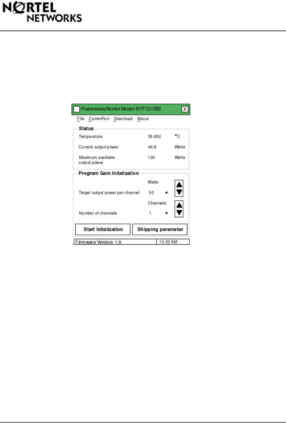
The calibration procedure for 1 carrier only is the same as above with the exception of the
following parameter changes. (again, this assumes that the level going into the MCPA shelf has
been set to 13 dBm):
Computer Screen for 1 Carrier Calibration
Target output power per channel: enter “50”
Number of channels: enter “1” (same as 2 Carrier calibration)
Potential Calibration Problems
If the calibration software reads “trying to connect to Nortel rack” at the bottom of the screen,
the software cannot detect the MCPA rack, therefore do the following:
ensure the com port used on the computer is the same as in the “CommPort” pull down menu on
the user interface screen.
ensure the RS-232 interface cable is connected to the proper MCPA shelf connector “J6”.
ensure the RS-232 interface cable is connected to the proper MCPA shelf.

This document contains Proprietary Information of Northern Telecom Limited. This information is considered to be
CONFIDENTIAL and should be treated appropriately.
If the software sets the output power to the incorrect power level, do the following:
Check that “Maximum Available Output Power” reads 120 Watts (this would indicate the rack
recognizes all 3 PA’s). If not, check that all 3 PA’s are enabled. If so, there may be a problem
with one of the PA’s.
If a "Run-time error" occurs every time the user interface software is executed, do the following:
Use the Windows Explorer to view the Windows directory.
Double-click on the "REGEDIT.EXE" file
A Registry Editor will open.
Double click on the directory "HKEY_CURRENT_USER"
Double-click on the directory "SOFTWARE"
Double-click on the directory "VB and VBA Program Settings"
Double-click on the directory "Powerwave RD Testing"
Double-click on the directory "System"
In the file panel there is a file called "CommAlarmBoard," double-click on it.
A dialog box will open and a "1" should be typed in the "value data:" entry box. This refers to
Comm 1. If there is already a 1, you might want to try 2,3 or 4.
Choose "OK." The number "1" or the number you entered should be displayed in the data
column next to the CommAlarmBoard.
Close the Registry Editor.
Try executing the user interface software again.
The reason you get this error is choosing a comm port that is not available. Verify that another
program is not open and using the comm port that the user interface software is trying to use.
TDMA Equipment List
This document contains Proprietary Information of Northern Telecom Limited. This information is considered to be
CONFIDENTIAL and should be treated appropriately.
The following list identifies the materials required for the TDMA system. It identifies
provisionable items and separate piece parts that must be ordered with the TMDA frame. This
list does NOT include the materials for the CDMA system or the interconnect kit.
Table 1: TDMA Equipment List
Quantity PEC CPC Description
1NTFC01AE A0732588 DMU Phase 2B RF Frame
Provision frame with one or two
1 or 2 NTFC07BB A0732402 MCPA Shelf
Piece parts
1 to 6 NTFC07BAMCPA
1P0857101 Duplexer Tray
4P0818520 Mounting Screws
1 or 2 NTFC04AB A0665954 Full band Duplexer
1NTFC12AA A0668379 Floor Anchoring Kit M12 (Seismic)
1NTFB40AA A0634172 Frame Leveling Kit
4 to 8 A0689593 50 ohm termination (for MCPA shelf input)
1 or 2 A0723535 RF Cable MCPA Shelf to Duplexer
1NTFC07BC A0743941 MCPA Shelf Interface Software (Note 1)