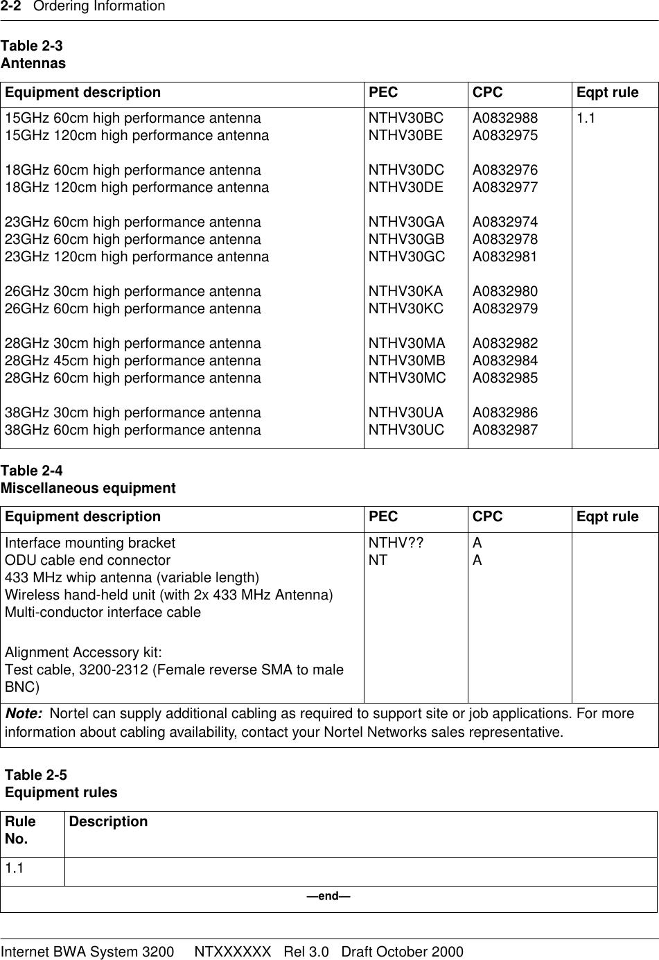
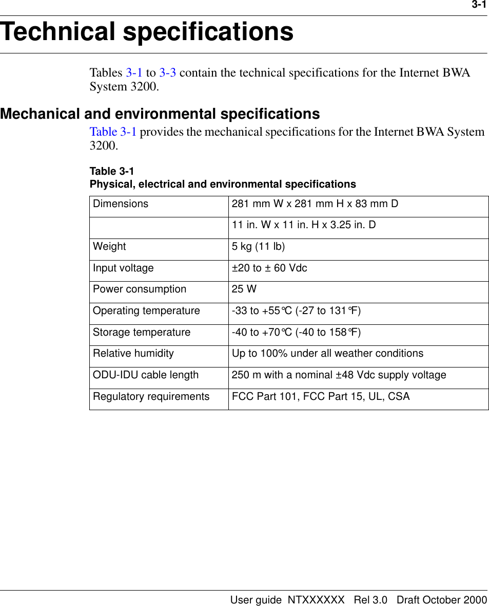
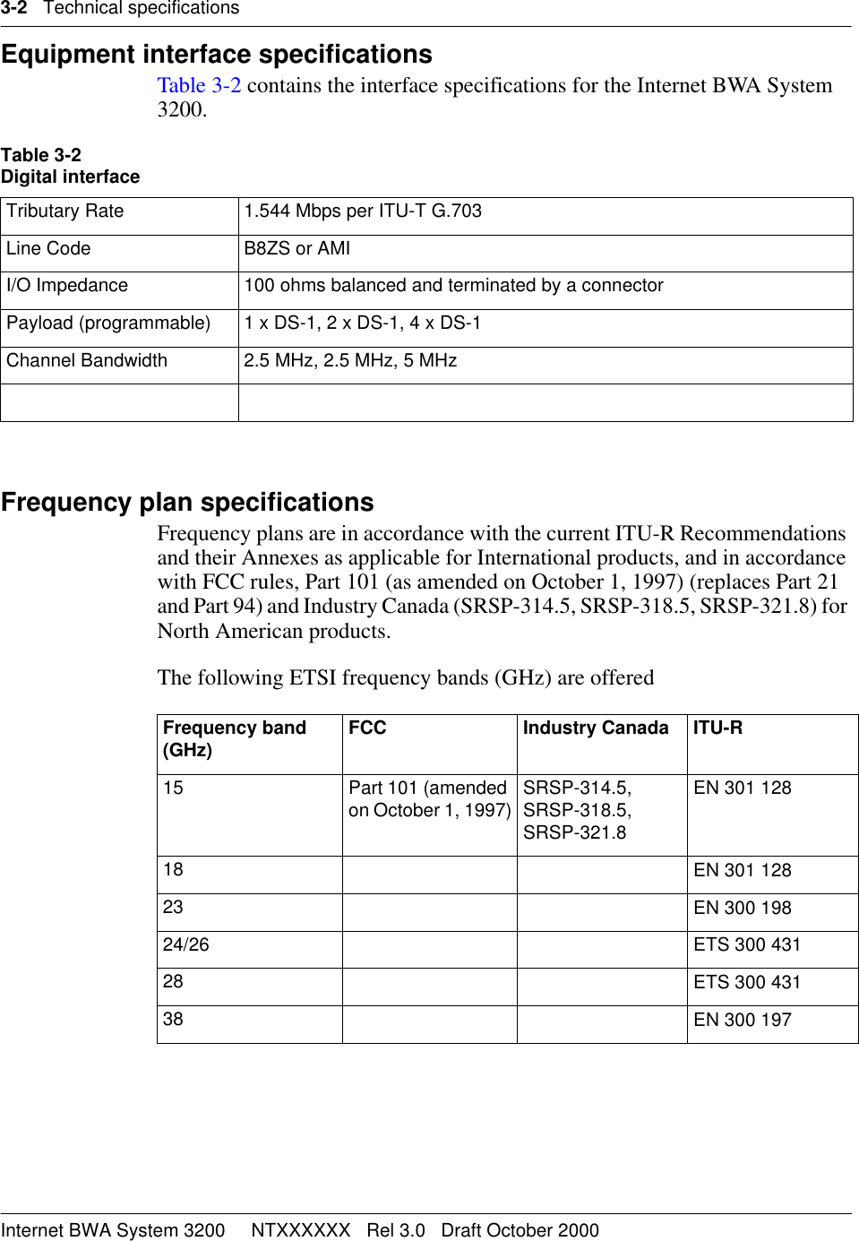
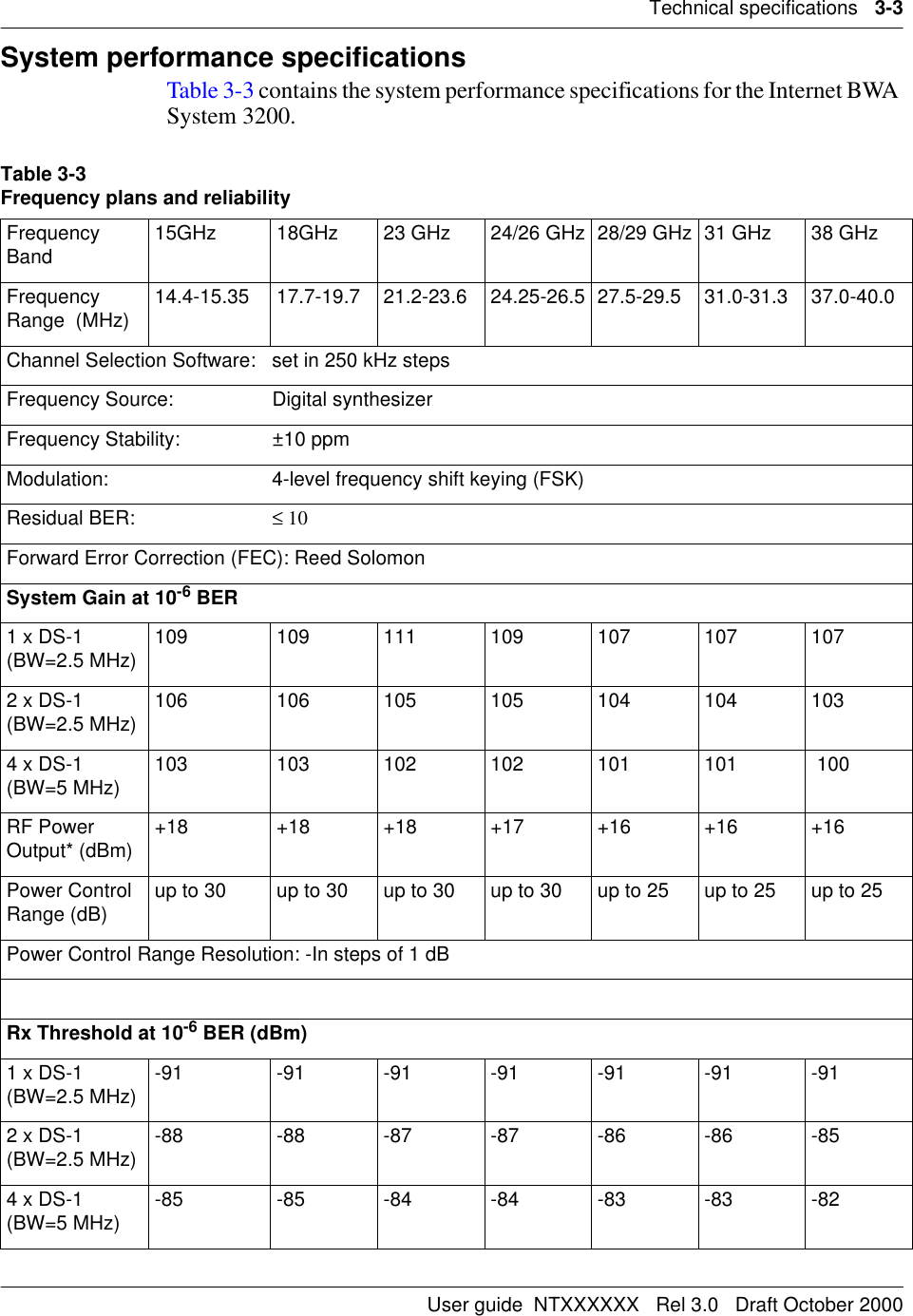
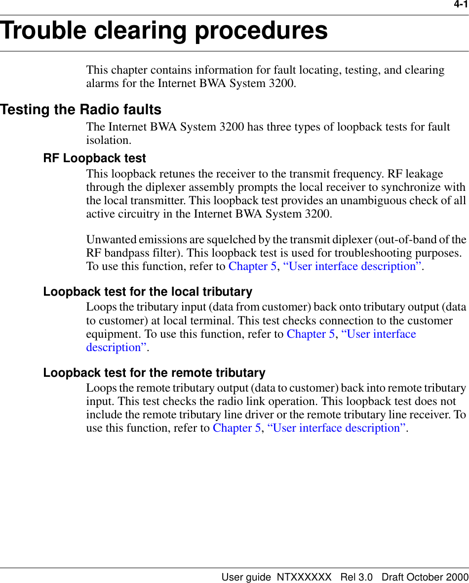
Avaya Canada NTHV5XG IBWA System 3200 (23 GHz) User Manual User Guide

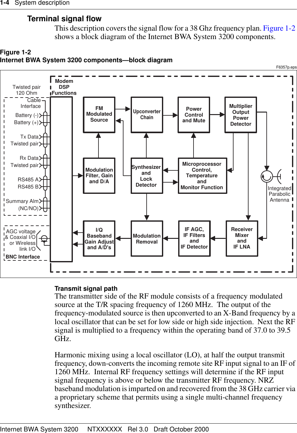
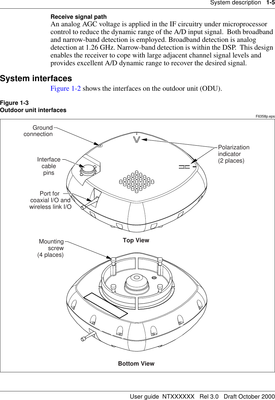
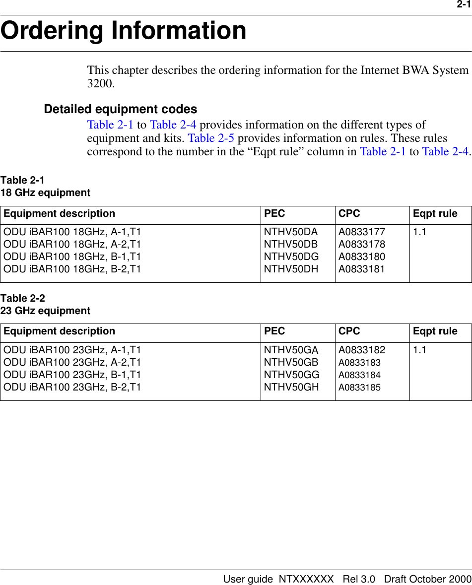
Avaya Canada Corporation IBWA System 3200 (23 GHz) User Guide

User Guide

NTXXXXXXInternet Broadband Wireless AccessInternet BWA System 3200User guideDraft   Rel 3.0   October 2000What’s inside...System descriptionOrdering InformationTechnical specificationsTrouble clearing proceduresUser interface descriptionInstallation and commissioning procedures
Copyright  2000 Nortel Networks, All Rights ReservedThe information contained herein is the property of Nortel Networks and is strictly confidential. Except as expressly authorized in writing by Nortel Networks, the holder shall keep all information contained herein confidential, shall disclose it only to its employees with a need to know, and shall protect it, in whole or in part, from disclosure and dissemination to third parties with the same degree of care it uses to protect its own confidential information, but with no less than reasonable care. Except as expressly authorized in writing by Nortel Networks, the holder is granted no rights to use the information contained herein.Nortel Networks, the Nortel Networks logo, the Globemark, How the World Shares Ideas, and Unified Networks are trademarks of Nortel Networks.Printed in Canada
User guide  NTXXXXXX   Rel 3.0   Draft October 2000iiiContents 0About this document vSystem description 1-1Overview 1-1Frequency band 1-1Capacity 1-1Frequency plan 1-2System features 1-2Equipment layout and main assemblies 1-3Terminal signal flow 1-4System interfaces 1-5Interface cable pins 1-6Hand-held terminal interface 1-6Ordering Information 2-1Detailed equipment codes 2-1Technical specifications 3-1Mechanical and environmental specifications 3-1Equipment interface specifications 3-2Frequency plan specifications 3-2System performance specifications 3-3Trouble clearing procedures 4-1Testing the Radio faults 4-1RF Loopback test 4-1Loopback test for the local tributary 4-1Loopback test for the remote tributary 4-1Clearing the Radio alarms 4-2Alarm interface pins 4-4Warranty and field support 4-5Warranties 4-5Standard return service 4-548-hour emergency service 4-7Technical support and information 4-7User interface description 5-1Hand-held terminal description 5-1
iv   ContentsInternet BWA System 3200     NTXXXXXX   Rel 3.0   Draft October 2000Hierarchy of the HHT menus 5-3Functions of the HHT keypad keys 5-4Parameters for the Near Radio menu 5-5Control submenu 5-5Status submenu 5-6Inventory submenu 5-8Test submenu 5-9Parameters for the Far Radio menu 5-10Control submenu 5-10Parameters for the Link menu 5-10Control submenu 5-10Installation and commissioning procedures 6-1Chapter task list 6-1List of procedures6-1  Unpacking, identifying and matching the system 6-26-2  Installing the Internet BWA System 3200 on a pole 6-56-3  Connecting the interface cables 6-136-4  Setting up the Internet BWA System 3200 6-176-5  Aligning the antenna of the Internet BWA System 3200 6-206-6  Commissioning the Internet BWA System 3200 6-24
User guide  NTXXXXXX   Rel 3.0   Draft October 2000vAbout this document 0This section provides an overview of the Internet BWA System 3200 user guide. AudienceThis document is intended for:• installers• system line-up and test (SLAT) engineers/technicians• maintenance engineersUser interface conventionsThe following conventions are used in procedures in this document.bold Bold entries identify a command or a userID entered by means of the craft interface terminal (CIT).↵↵↵↵This symbol means the return key must be pressed.Bold Bold entries with initial capital letters identify buttons, fields and menu items as seen on the user interface screen.
vi   About this documentInternet BWA System 3200     NTXXXXXX   Rel 3.0   Draft October 2000
User guide  NTXXXXXX   Rel 3.0   Draft October 20001-1System description 1-This document describes the Internet BWA System 3200. OverviewThe Internet BWA System 3200 establishes high-speed, reliable point-to-point wireless links. The Internet BWA System 3200 uses a 4-FSK modulation scheme and carries up to four E1 (2.048 Mbits/s) or up to four DS1 (1.544 Mbits/s) signals.Frequency bandThe Internet BWA System 3200 operates in the 15, 18, 23, 24/26, 28, 31 and 38 GHz frequency ranges. CapacityThe capacity upgrade is software programmable from 2xE1 to 4xE1 and from 1xDS1 to 2xDS1 to 4xDS1. The capacity upgrade affects traffic because the upgrade changes the following parameters:• occupied bandwidth• receive baseband filters• data rate of operationTable 1-1 lists the bandwidths for the radio frequency (RF) channels.Table 1-1RF channel bandwidthsCapacity Channel bandwidth (MHz)2 x E1 3.5 (for all frequencies)4 x E1 7.0 (for all frequencies)1 or 2 x DS1 2.5 (for all frequencies)4 x DS1 5.0 (for all frequencies)
1-2   System descriptionInternet BWA System 3200     NTXXXXXX   Rel 3.0   Draft October 2000For systems with a specific capacity (for example, a 4 x E1 capacity), the activation of a new tributary within that capacity is software programmable, either locally or remotely. The activation of a new tributary within an existing capacity does not cause any errors to the existing traffic. Inactive tributaries do not cause alarms. Frequency planFrequency plans are in accordance with:• current ITU-R recommendations and annexes as applicable for international products• FCC rules, part 101 (as amended on October 1, 1997, replaces parts 21 and 94)• Industry Canada (SRSP-314.5, SRSP-318.5, SRSP-321.8) for North American productsTable 1-2 lists the frequency plans.System featuresThe Internet BWA System 3200 provides:• scalable channel capacity to precisely match traffic volume• scalable channel selection (digital synthesizer set in 250 kHz steps)• selectable AMI or B8ZS line coding for DS1 signals (E1 signals use HDB3 coding only)• selectable framing type (Unframe, Frame or ESF for DS1 signals)• hand-held wireless terminal to perform configuration, maintenance, and performance monitoring of the outdoor unit (ODU)• receive signal strength indicator (RSSI) on the outdoor unit to guide service personnel in antenna alignment• forward error correction (FEC) and link ID codes• common ODU and frequency synthesizer to minimize the number of spare units and cost• simple installation and maintenance from the “twist and lock” design of the outdoor unit.Table 1-2Frequency plansFrequency band 15 GHz 18 GHz 23 GHz 24/26 GHz 28/29 GHz 31 GHz 38 GHzFrequency range (MHz) 14.4- 15.35 17.7- 19.7 21.2- 23.6 24.25- 26.5 27.5- 29.5 31.0- 31.3 37.0- 40.0
System description   1-3User guide  NTXXXXXX   Rel 3.0   Draft October 2000Equipment layout and main assembliesThe Internet BWA System 3200 includes an outdoor unit (ODU), an antenna and a mounting assembly (see Figure 1-1). A terminal site requires one Internet BWA System 3200 to handle the radio signals for both the east and west directions. Figure 1-1Internet BWA System 3200—physical layoutMOP0082t.epsOutdoor unitThe outdoor unit contains a Modem, an RF module, a power supply and a remote communication link. Removal of the outdoor unit is possible without the need to realign the antenna. Mounting assemblyThe Internet BWA System 3200 includes a mounting assembly to hold the radio to a pipe mount. The mounting assembly design provides three 30° elevation adjustment increments for a 90° elevation adjustment range. The mounting assembly design also provides two 45° azimuth adjustment increments for a 90° azimut adjustment range. MountingassemblyInterface cableassemblyOutdoor unitAntenna
1-4   System descriptionInternet BWA System 3200     NTXXXXXX   Rel 3.0   Draft October 2000Terminal signal flowThis description covers the signal flow for a 38 Ghz frequency plan. Figure 1-2 shows a block diagram of the Internet BWA System 3200 components.Figure 1-2Internet BWA System 3200 components—block diagramF6357p.epsTransmit signal pathThe transmitter side of the RF module consists of a frequency modulated source at the T/R spacing frequency of 1260 MHz.  The output of the frequency-modulated source is then upconverted to an X-Band frequency by a local oscillator that can be set for low side or high side injection.  Next the RF signal is multiplied to a frequency within the operating band of 37.0 to 39.5 GHz.  Harmonic mixing using a local oscillator (LO), at half the output transmit frequency, down-converts the incoming remote site RF input signal to an IF of 1260 MHz.  Internal RF frequency settings will determine if the RF input signal frequency is above or below the transmitter RF frequency. NRZ baseband modulation is imparted on and recovered from the 38 GHz carrier via a proprietary scheme that permits using a single multi-channel frequency synthesizer.MicroprocessorControl,TemperatureandMonitor FunctionSynthesizerandLockDetectorModulationFilter, Gainand D/AUpconverterChainFMModulatedSourceMultiplierOutputPowerDetectorPowerControland MuteModulationRemovalI/QBasebandGain Adjustand A/D'sReceiverMixerandIF LNAIF AGC,IF FiltersandIF DetectorIntegratedParabolicAntennaModemDSPFunctionsBattery (-)Battery (+)Tx DataTwisted pairRx DataTwisted pairRS485 ARS485 BSummary Alm(NC/NO)CableInterfaceBNC InterfaceAGC voltage& Coaxial I/Oor Wirelesslink I/OTwisted pair120 Ohm
System description   1-5User guide  NTXXXXXX   Rel 3.0   Draft October 2000Receive signal pathAn analog AGC voltage is applied in the IF circuitry under microprocessor control to reduce the dynamic range of the A/D input signal.  Both broadband and narrow-band detection is employed. Broadband detection is analog detection at 1.26 GHz. Narrow-band detection is within the DSP.  This design enables the receiver to cope with large adjacent channel signal levels and provides excellent A/D dynamic range to recover the desired signal.System interfacesFigure 1-2 shows the interfaces on the outdoor unit (ODU).Figure 1-3Outdoor unit interfacesF6358p.epsPort for coaxial I/O andwireless link I/OInterfacecablepinsGroundconnectionMountingscrew(4 places)Top ViewBottom ViewPolarization indicator(2 places)
1-6   System descriptionInternet BWA System 3200     NTXXXXXX   Rel 3.0   Draft October 2000Interface cable pinsThe interface cable pins connect:• Up to four E1 lines (120 Ohm, balanced) or up to four DS1 lines (100 Ohm, balanced)• DC power• alarm telemetry information• two relays for summable and programmable alarms• two dry-contact (Form-C) relay outputs that report on link performance and critical alarmsHand-held terminal interfaceThe Internet BWA System 3200 includes an optional wireless hand-held terminal (HHT) that operates with batteries.  The HHT communicates with the Internet BWA System 3200 using an unlicensed 433.92 MHz channel. To support this channel, both the HHT and the outdoor unit (ODU) have radio 433.92 MHz transceivers and matching whip antennas. You can use the HHT to set and control, and to monitor the following features: • receive signal strength indicator (RSSI) for antenna alignment• Transmit Mute• Transmit Modulation• Transmitter Frequency• Receiver Frequency• radio frequency (RF) Filter Bandwidth• bit error rate (BER)• Link ID• ODU Temperature• Software Revision• Fault Alarms
User guide  NTXXXXXX   Rel 3.0   Draft October 20002-1Ordering Information 2-This chapter describes the ordering information for the Internet BWA System 3200. Detailed equipment codesTable 2-1 to Table 2-4 provides information on the different types of equipment and kits. Table 2-5 provides information on rules. These rules correspond to the number in the “Eqpt rule” column in Table 2-1 to Table 2-4.Table 2-118 GHz equipmentEquipment description PEC CPC Eqpt ruleODU iBAR100 18GHz, A-1,T1ODU iBAR100 18GHz, A-2,T1ODU iBAR100 18GHz, B-1,T1ODU iBAR100 18GHz, B-2,T1NTHV50DANTHV50DBNTHV50DGNTHV50DHA0833177A0833178 A0833180A0833181 1.1Table 2-223 GHz equipmentEquipment description PEC CPC Eqpt ruleODU iBAR100 23GHz, A-1,T1ODU iBAR100 23GHz, A-2,T1ODU iBAR100 23GHz, B-1,T1ODU iBAR100 23GHz, B-2,T1NTHV50GANTHV50GBNTHV50GGNTHV50GHA0833182A0833183 A0833184 A0833185 1.1
2-2   Ordering InformationInternet BWA System 3200     NTXXXXXX   Rel 3.0   Draft October 2000Table 2-3AntennasEquipment description PEC CPC Eqpt rule15GHz 60cm high performance antenna15GHz 120cm high performance antenna18GHz 60cm high performance antenna18GHz 120cm high performance antenna23GHz 60cm high performance antenna23GHz 60cm high performance antenna23GHz 120cm high performance antenna26GHz 30cm high performance antenna26GHz 60cm high performance antenna28GHz 30cm high performance antenna28GHz 45cm high performance antenna28GHz 60cm high performance antenna38GHz 30cm high performance antenna38GHz 60cm high performance antennaNTHV30BCNTHV30BENTHV30DCNTHV30DENTHV30GANTHV30GBNTHV30GCNTHV30KANTHV30KCNTHV30MANTHV30MBNTHV30MCNTHV30UANTHV30UCA0832988A0832975A0832976A0832977A0832974A0832978A0832981A0832980A0832979A0832982A0832984A0832985A0832986A08329871.1Table 2-4Miscellaneous equipmentEquipment description PEC CPC Eqpt ruleInterface mounting bracket ODU cable end connector 433 MHz whip antenna (variable length) Wireless hand-held unit (with 2x 433 MHz Antenna)Multi-conductor interface cableAlignment Accessory kit:Test cable, 3200-2312 (Female reverse SMA to male BNC) NTHV?? NT  A A Note:  Nortel can supply additional cabling as required to support site or job applications. For more information about cabling availability, contact your Nortel Networks sales representative.Table 2-5Equipment rulesRule No. Description1.1—end—
Ordering Information   2-3User guide  NTXXXXXX   Rel 3.0   Draft October 2000
2-4   Ordering InformationInternet BWA System 3200     NTXXXXXX   Rel 3.0   Draft October 2000
User guide  NTXXXXXX   Rel 3.0   Draft October 20003-1Technical specifications 3-Tables 3-1 to 3-3 contain the technical specifications for the Internet BWA System 3200.Mechanical and environmental specificationsTable 3-1 provides the mechanical specifications for the Internet BWA System 3200. Table 3-1Physical, electrical and environmental specificationsDimensions 281 mm W x 281 mm H x 83 mm D 11 in. W x 11 in. H x 3.25 in. D Weight 5 kg (11 lb) Input voltage  ±20 to ± 60 Vdc Power consumption  25 W Operating temperature  -33 to +55°C (-27 to 131°F) Storage temperature  -40 to +70°C (-40 to 158°F) Relative humidity  Up to 100% under all weather conditionsODU-IDU cable length  250 m with a nominal ±48 Vdc supply voltageRegulatory requirements  FCC Part 101, FCC Part 15, UL, CSA
3-2   Technical specificationsInternet BWA System 3200     NTXXXXXX   Rel 3.0   Draft October 2000Equipment interface specificationsTable 3-2 contains the interface specifications for the Internet BWA System 3200. Table 3-2Digital interfaceFrequency plan specificationsFrequency plans are in accordance with the current ITU-R Recommendations and their Annexes as applicable for International products, and in accordance with FCC rules, Part 101 (as amended on October 1, 1997) (replaces Part 21 and Part 94) and Industry Canada (SRSP-314.5, SRSP-318.5, SRSP-321.8) for North American products.The following ETSI frequency bands (GHz) are offeredTributary Rate  1.544 Mbps per ITU-T G.703Line Code  B8ZS or AMII/O Impedance  100 ohms balanced and terminated by a connectorPayload (programmable)  1 x DS-1, 2 x DS-1, 4 x DS-1Channel Bandwidth  2.5 MHz, 2.5 MHz, 5 MHzFrequency band (GHz) FCC  Industry Canada  ITU-R 15 Part 101 (amended on October 1, 1997) SRSP-314.5, SRSP-318.5, SRSP-321.8EN 301 12818 EN 301 12823 EN 300 19824/26 ETS 300 43128 ETS 300 43138 EN 300 197
Technical specifications   3-3User guide  NTXXXXXX   Rel 3.0   Draft October 2000System performance specificationsTable 3-3 contains the system performance specifications for the Internet BWA System 3200. Table 3-3Frequency plans and reliability Frequency Band 15GHz 18GHz 23 GHz 24/26 GHz 28/29 GHz 31 GHz 38 GHzFrequency Range  (MHz) 14.4-15.35 17.7-19.7 21.2-23.6 24.25-26.5 27.5-29.5 31.0-31.3 37.0-40.0Channel Selection Software:  set in 250 kHz stepsFrequency Source:  Digital synthesizerFrequency Stability: ±10 ppmModulation:  4-level frequency shift keying (FSK)Residual BER:  ≤ 10Forward Error Correction (FEC): Reed SolomonSystem Gain at 10-6 BER 1 x DS-1 (BW=2.5 MHz)  109  109 111 109 107 107 107 2 x DS-1 (BW=2.5 MHz)  106 106 105 105 104 104 1034 x DS-1 (BW=5 MHz)  103 103 102 102 101 101  100RF Power Output* (dBm)  +18  +18 +18 +17 +16 +16 +16Power Control Range (dB)  up to 30  up to 30  up to 30  up to 30  up to 25  up to 25  up to 25 Power Control Range Resolution: -In steps of 1 dBRx Threshold at 10-6 BER (dBm)1 x DS-1 (BW=2.5 MHz)  -91  -91 -91 -91 -91 -91 -91 2 x DS-1 (BW=2.5 MHz)  -88 -88 -87 -87 -86 -86 -854 x DS-1 (BW=5 MHz)  -85 -85 -84 -84 -83 -83 -82
3-4   Technical specificationsInternet BWA System 3200     NTXXXXXX   Rel 3.0   Draft October 2000
User guide  NTXXXXXX   Rel 3.0   Draft October 20004-1Trouble clearing procedures  4-This chapter contains information for fault locating, testing, and clearing alarms for the Internet BWA System 3200. Testing the Radio faultsThe Internet BWA System 3200 has three types of loopback tests for fault isolation.RF Loopback testThis loopback retunes the receiver to the transmit frequency. RF leakage through the diplexer assembly prompts the local receiver to synchronize with the local transmitter. This loopback test provides an unambiguous check of all active circuitry in the Internet BWA System 3200.Unwanted emissions are squelched by the transmit diplexer (out-of-band of the RF bandpass filter). This loopback test is used for troubleshooting purposes. To use this function, refer to Chapter 5, “User interface description”. Loopback test for the local tributaryLoops the tributary input (data from customer) back onto tributary output (data to customer) at local terminal. This test checks connection to the customer equipment. To use this function, refer to Chapter 5, “User interface description”.Loopback test for the remote tributaryLoops the remote tributary output (data to customer) back into remote tributary input. This test checks the radio link operation. This loopback test does not include the remote tributary line driver or the remote tributary line receiver. To use this function, refer to Chapter 5, “User interface description”.
4-2   Trouble clearing proceduresInternet BWA System 3200     NTXXXXXX   Rel 3.0   Draft October 2000Clearing the Radio alarms Table 4-1 lists the Internet BWA System 3200 alarms, an explanation of the alarm, the probable cause, and the action required to clear it. Table 4-1iBAR-100 system alarmsAlarm Explanation Probable cause Action requiredTributary N Tx LOS The Internet BWA System 3200 cannot detect a signal at the tributary input. Defective customer equipment connected to Internet BWA System 3200.Verify customer equipment. Replace if defective.Internet BWA System 3200 cable is disconnected. Connect cable.The cable from customer test set to Internet BWA System 3200 is disconnected.Connect test set cable.Tx low output power Far-end radio is reporting that the RSSI from the local radio is too lowInsufficient Tx power setting at the local site.  Increase Tx power setting at the local site. Atmospheric problems Wait for the end of atmospheric problemsRx Frame Loss (radio) The receiver has detected a loss of frame condition on the Radio channel.There is a Tx failure at the far-end site. Check for other alarms in the system.Severe propagation (RSSI is very low). Check that the Tx power is set correctly at the far-end site.Check the RF cables.Wait for the end of propagation activity.Low RSSI  The performance degradation threshold has been crossed.Minor propagation activity. If the RSSI is lower than the threshold, wait for the end of propagation activity.Waveguide or RF connector is incorrectly installed. Verify the waveguide and cabling connection.
Trouble clearing procedures   4-3User guide  NTXXXXXX   Rel 3.0   Draft October 2000Equipment failure. If the RSSI is identical to the expected value, and the alarm remains active for a long period of time, then a component may be defective. If necessary, replace the ODU at the local site or the far-end site. Tributary N Rx AIS  The Internet BWA System 3200 is receiving an AIS signal from the far-end radio. Defective customer equipment at tributary N at the far-end. The far-end radio has a Tributary N Tx LOS alarm at tributary N. Verify customer equipment. Replace if defective. AFC Loop OOL The automatic frequency control (AFC) loop is out of loop. AGC Loop OOL The automatic gain control (AGC) loop is out of loop. TX synthesizer OOL There is a failure of the Tx synthesizer.  The Tx synthesizer is defective. Reset the Tx frequency.Replace the ODU.RX synthesizer OOL There is a failure of the Rx synthesizer.  The Rx synthesizer is defective. Reset the Rx frequency or replace the ODU.Temperature over-range or under-rangeThe temperature of the unit is above or below the safe operating range.Frame-Alignment-Word (FAW) mismatch  The far-end radio is not transmitting the correct FAW (link ID). The far-end radio was not commissioned with the same FAW as the local radio. Commission the two radios to have the same FAW. Table 4-1 (continued)iBAR-100 system alarmsAlarm Explanation Probable cause Action required
4-4   Trouble clearing proceduresInternet BWA System 3200     NTXXXXXX   Rel 3.0   Draft October 2000Alarm interface pinsThe alarm interface pins refer to pins 12, 18 and 23 from the 31-pin interface on the ODU (see Table 4-2).Table 4-2Pin assignments for the 31-pin interfacePin Description Pin Description1  Case Gnd  17  RX Tributary 3 Ring2 Reserved 18 Summary Alarm relay (NC)3  TX Tributary 1 Tip  19  TX Tributary 4 Tip4  TX Tributary 1 Ring  20  TX Tributary 4 Ring5  RX Tributary 1 Tip  21  RX Tributary 4 Tip6  RX Tributary 1 Ring  22  RX Tributary 4 Ring7  RS 485+  23 Alarm relay Common (CC)8  TX Tributary 2 Tip  24  DC Power Conn#19  TX Tributary 2 Ring  25  RS422 RX+10  RX Tributary 2 Tip  26  RS422 RX-11 RX Tributary 2 Ring  27  DC Power Conn#212 Programmable Alarm Relay (NC)  28 RS422 TX- 13 RS 485-  29  RS422 TX+14  TX Tributary 3 Tip  30  DC Power Conn#215  TX Tributary 3 Ring  31  DC Power Conn#116  RX Tributary 3 Tip
Trouble clearing procedures   4-5User guide  NTXXXXXX   Rel 3.0   Draft October 2000The descriptions of the alarm pins in Table 4-2 on page 4-4 are:• summary alarm relay (pin 18): — activates when any of the alarms in Table 4-1 on page 4-2 are active— the relay contact is open in normal condition and closes in alarm condition• programmable alarm relay (pin 12): — activates when a programmed alarm is on. A programmed alarm can be any of the alarms in Table 4-1 on page 4-2 (as provisioned by the customer)— The relay contact is closed in normal condition and open in alarm condition• Alarm relay common (pin 23):— common (ground) contact for both pins 12 and 18Warranty and field supportThis section covers warranties and technical support information.WarrantiesNortel Networks Public Networks Division warrants products to be free from defects in material and workmanship for a period of: • twelve (12) months from the date of shipment on a “furnish only” basis• twelve (12) months from the date of acceptance or eighteen (18) months from the date of shipment for material supplied on an engineer, furnish and install (E, F, and I) basis, whichever is the shorter period Standard return serviceA replacement unit is shipped prepaid to the customer. During normal business hours, you can call the repairs and emergencies department and receive authorization to return the defective item. After marking the item with the assigned repair order number and a description of the fault, ship the item prepaid to: For customers in Canada: Nortel Networks9300 Trans Canada HighwaySt. Laurent, QC H4S 1K5 Att: Repairs and Emergencies, Dept. 4350 Tel:  1-888-594-8474 (English or French)Select option 3 for Radio
4-6   Trouble clearing proceduresInternet BWA System 3200     NTXXXXXX   Rel 3.0   Draft October 2000For customers in the United States: Nortel Networks 917 Air Park Center DriveNashville, TN37217Att: Repair and Return Tel.: 1-800-251-1758 For customers in the Caribbean and Latin America: Nortel Networks (CALA)1500 Concord Terrace Sunrise, FLU.S.A.33323-2815Att: Repair Coordinator Tel.: (954) 851-8449 For customers in China: Nortel Networks China Limited11/F, Nortel Tower, Sun Dong An PlazaNo.138, Wang Fu Jing StreetBeijing 100006, ChinaTel: 86-10-6528 8877Fax: 86-10-6528 070186-10-6528 0702For customers in Australia: Nortel Networks Distribution CentreUnit 2, Parklands Estate21 South StreetRydalmere NSW Australia 2116Tel: 612-9325-5301Fax: 612-9937-7154For customers in Singapore: Nortel Networks Singapore Pte. Ltd.c/o Emery Worldwide4, Changi South LaneNan Wah BuildingSingapore 486127Tel:  (61) 2 8870 5480 (Sydney)Fax: (61) 2 8870 7154 (Sydney)
Trouble clearing procedures   4-7User guide  NTXXXXXX   Rel 3.0   Draft October 2000For customers in the Philippines: Nortel Philippines Repair Centerc/o Skyfreight Forwarders Inc.AEI Liaison OfficeNinoy Aquino AvenueParanaque, Metro ManilaPhilippinesTel: (632) 917-4401Fax: (632) 917-414548-hour emergency serviceDuring and after normal business hours, you can call the repairs and emergencies department:• United States: 1-800-423-9658• Canada: 1-800-361-2575Request an emergency replacement and provide:• your name • your company name • your telephone number • your exact unit code and name • your shipping address The repair coordinator assigns a repair order number that must be marked on the unit being returned. Ship the unit prepaid to the same address as the standard repair service. At the same time, Nortel Networks will ship an identical replacement unit prepaid to within 48 hours. Technical support and informationThe support that the service centers provide includes: • emergency support for a service-affecting problem• trouble clearing guidance • product maintenance support • retrofit procedure inquiries • support for hardware and software issues• explanation and clarification of Nortel Technical Publication (NTP) documentation.
4-8   Trouble clearing proceduresInternet BWA System 3200     NTXXXXXX   Rel 3.0   Draft October 2000Customers can direct requests for additional information to the nearest technical assistance service center (see Table 4-3). Fax-on-demand serviceCustomers can obtain technical information about selected Nortel Networks TransportNode products through the 24 hour fax-on-demand telephone service. In the United States and Canada, customers can reach this service at the following toll-free number: 1-800-451-1685.Table 4-3Technical assistance service centers For problems that affect serviceFor 24-hour emergency recovery or software upgrade support for:• restoration of service for equipment that has been carrying traffic and is out of service• issues that prevent traffic protection-switching• issues that prevent completion of software upgrades• restoration of service for equipment that has been carrying traffic and is experiencing signal degradationUnited States: 1-800-275-3827 (1-800-ASK-ETAS)Canada:1-800-361-2465International: 770-708-4985For problems that do not affect serviceFor 24-hour support for:• issues that require immediate assistance• technical support and upgrade notification(8 a.m. to 10 p.m. EST only).United States: 1-800-275-8726 (1-800-ASK-TRAN)Canada:1-800-361-2465International: 770-708-4981
User guide  NTXXXXXX   Rel 3.0   Draft October 20005-1User interface description 5-This chapter describes how to use wireless hand-held terminal (HHT). The HHT operates on batteries and allows quick and easy monitoring and changes to the system parameters of the Internet BWA System 3200. Hand-held terminal descriptionThe HHT can operate within 75 meters (225 feet) of the ODU. The LCD display provides visual access to a series of system software menus and parameters on two lines of 16 characters each. The HHT gives access to a series of menus with provisioning, monitoring, control, maintenance and query commands for the Internet BWA System 3200. • The HHT remains active until the user logs off or the HHT loses communication with the Internet BWA System 3200. • When viewing or setting parameters, the HHT powers down 60 seconds after the last entry. • Under normal operating conditions, normal battery life is 25 hours with the use of industrial-grade alkaline cells, .• The HHT can lock up when the batteries are weak or not correctly installed. If the HHT locks up, remove and insert the batteries again.
5-2   User interface descriptionInternet BWA System 3200     NTXXXXXX   Rel 3.0   Draft October 2000• If you enter incorrect data, “Invalid Value” appears on the LCD. The circuit is usually in a muted state. The channel opens when the HHT issues a command. The HHT can communicate to the ODU of the Internet BWA System 3200 with the use of either:• a wireless channel (418 MHz or 433.92 MHz channel with the use the of whip antennas on the ODU and on the HHT)• a coaxial cable (RG-58U cable) that connects between the ODU and the HHTRefer to Figure 1-3 on page 1-5 for the location of the wireless link or coaxial I/O port.
User interface description   5-3User guide  NTXXXXXX   Rel 3.0   Draft October 2000Hierarchy of the HHT menusThe HHT user interface is menu driven.  The menus allow you to set and view the parameters for the local and the far-end radios. Figure 5-1 shows the hierarchy of the HHT menus.Figure 5-1The HHT menus hierarchyR0015p.epsStatusODU Address: Serial numberTx Freq Rx FreqTx PowerFAWCapacityCbl LngthLine CodingTribut EnabTx FreqRx FreqTx PowerFAWCapacityCbl LngthLine CodingTribut StatMuteTx Freq RngRx Freq RngRSSITempBlk Error CntSum AlarmsPECProd rel verSer NoODU SWDSP SWMuteLocal loopbackRF loopbackRem loopbackLine CodingTribut EnabFreqTx PowerFAWCapacityNear RadioEnterEnterEnter & holdControlEnterMenuFar Radio Enter ControlLink Enter ControlEnterMenuEnterMenuEnterMenuEnterMenuEnterMenuInventoryTest
5-4   User interface descriptionInternet BWA System 3200     NTXXXXXX   Rel 3.0   Draft October 2000Functions of the HHT keypad keysAs Figure 5-1 shows, the menu items are:• Near Radio• Far Radio•LinkThe submenu items are:• Control•Inventory•Status•TestAfter you enter the radio terminal address, the “Near Radio” menu is the default menu item. Table 5-1lists the HHT keypad keys with the keypad key functions.Table 5-1HHT keypad keysKey Press this key to...scroll through all the menu or submenu itemsscroll through all the parameters within a submenuaccess a submenu within a menu item (see Figure 5-1)access the parameters within a submenuenter new values for the parametersreturn to the previous menu or submenu itemsdelete a keypad entry
User interface description   5-5User guide  NTXXXXXX   Rel 3.0   Draft October 2000Parameters for the Near Radio menuThis section describes the parameters within the submenus of the “Near Radio” menu itemControl submenuThis section lists the parameters within the “Control” submenu of the “Near Radio” menu. The “Control” submenu allows you to change to the parameters.Tx FreqTo enter a value to set the transmit RF frequency (in MHz). Values: see Chapter 3, “Technical specifications” for channel centersRx FreqTo enter a value to set the receive RF frequency (in MHz). Values: see Chapter 3, “Technical specifications” for channel centersTx PowerTo enter a value to set the transmit power level in dBm.Values: 18 to XX dBm (15/18/23 GHz) Recommended: 20 dBm17 to XX dBm (24/26 GHz) Recommended: 20 dBm16 to XX dBm (28 GHz) Recommended: 20 dBm16 to XX dBm (31/38 GHz)Recommended: 20 dBmFAWTo enter a value to select one of eight possible frame alignment words (FAW) in the radio frame. This is also used as the Link ID. Both near end and far end radios must have the same FAW. The Internet BWA System 3200 only processes a frame that contains the correct FAW. Values: 0 to 7 CapacityTo enter a value to set the number of tributaries that the radio can multiplex into the main channel. See also the “Tribut Enab” parameter for this submenu. Values: 2: include tributaries 1 and 2 4: include all tributaries (tributaries 1 to 4) Cbl LngthTo enter a value to indicate the length of the cable in meters. This parameter applies for DS1 systems only.Values: 0 to 40, 41 to 80, 81 to 121, 122 to 162, 163 to 200
5-6   User interface descriptionInternet BWA System 3200     NTXXXXXX   Rel 3.0   Draft October 2000Line CodingTo enter a value to select AMI or B8ZS coding for all tributaries. This parameter applies for DS1 systems only. For an E1 system, the line coding is always HDB3.Values: 0: AMI1: B8ZSTribut EnabTo enter a value to enable or disable tributaries 1 ot 4. A disabled tributary has no alarms. This parameter has two or four screens (one for each tributary) that refer to the “capacity” setting for the radio. See also the “Capacity” parameter in this submenu. Values: 0: disable 1: enable Status submenuThis section lists the parameters within the “Status” submenu of the “Near Radio” menu. The “Status” submenu allows you to only view to the parameters. Tx FreqTo view the transmit RF frequency (in MHz). Rx FreqTo view the receive RF frequency (in MHz). Tx PwrTo view the transmit power level in dB.Values: 40 dB (15/18/23 GHz) 30 dB (24/26/28 GHz) 25 dB (31/38 GHz) FAWTo view the assigned frame alignment word (FAW) in the radio frame. Values: 0 to 7 CapacityTo view the number of tributaries that the radio can multiplex into the main channel.Values: 2: include tributaries 1 and 2.4: include all tributaries (tributaries 1 to 4)
User interface description   5-7User guide  NTXXXXXX   Rel 3.0   Draft October 2000Cbl LngthTo view the length of the cable in meters. This parameter applies for DS1 systems only.Values: 0 to 40, 41 to 80, 81 to 121, 122 to 162, 163 to 200Line CodingTo view the DS1 line coding parameter (AMI or B8ZS) for all tributaries in the system. For an E1 system, the line coding is always HDB3.Values: 0: AMI1: B8ZSTrib StatTo view the status of tributaries 1 to 4. This parameter has two or four screens (one for each tributary) that refer to the number of tributaries that the radio can receive.Values: 0: disable 1: enable MuteTo view the status of the transmitter output. Values: 0: the Tx output is enabled1: the Tx output is muted (disabled)Tx Freq RngTo view the transmit frequency range.Values: 17.7 & 19.7 (18 GHz)21.2 & 23.6 (23 GHz)Rx Freq RngTo view the receive frequency range.Values: 17.7 & 19.7 (18 GHz)21.2 & 23.6 (23 GHz)RSSITo view the received signal strength indication (RSSI) value in dBm.Values: 0 to -86/89 dBm (18 GHz with 4/2 tributaries)0 to -85/88 dBm (23 GHz with 4/2 tributaries)TempView the internal temperature of the ODU. Values: -128 to +127 °C
5-8   User interface descriptionInternet BWA System 3200     NTXXXXXX   Rel 3.0   Draft October 2000Blk Error CntTo view the cumulative block error count from the FEC decoder. At this parameter, the system first reads the counter and then clears it.Values:Sum AlarmsTo view all active alarms. You can scroll through each active alarm. Refer to Chapter 4, “Trouble clearing procedures” for the alarm definitions. Values: Temperature overrange Temperature underrange  Tx low output power  Rx frame loss Low RSL  AFC loop OOL  AGC loop OOL Tx synthesizer OOL  Rx synthesizer OOL FAW error alarm  Data link alarmTributary 1 Tx LOS  Tributary 2 Tx LOS  Tributary 3 Tx LOS  Tributary 4 Tx LOS  Tributary 1 Rx AIS  Tributary 2 Rx AIS  Tributary 3 Rx AIS  Tributary 4 Rx AISInventory submenuThis section lists the parameters within the “Inventory” submenu of the “Near Radio” menu. PECDisplays the ODU PEC code Product rel verDisplays the ODU release versionSerial No. Displays the ODU serial number ODU SWDisplays the version number of the ODU controller software . The number has an implied decimal point before the last two digits (for example: 110 = version 1.10)
User interface description   5-9User guide  NTXXXXXX   Rel 3.0   Draft October 2000DSP SWDisplays the serial number of the digital signal processing (DSP) software. This is the version number in the revision register of the field programmable gate array (FPGA) . Values: 0 to 255 Test submenuThis section lists the parameters within the “Test” submenu of the “Near Radio” menu. The test menu allows you to disable the transmitter to perform loopback tests. Tx MuteTo enable or disable the transmitter.Values: 0: enable the Tx output1: disable (mute) the Tx outputlocal loopbkTo loopback local tributaries 1to 4. Loops the tributary input (data from customer) back onto tributary output (data to customer) at local terminal. This test checks connection to the customer equipment. This parameter has two or four screens that refer to the “capacity” setting for the radio.Values:  0: disabled  1: enabled RF loopbkWhen you enable the RF loopback, the system changes the Rx frequency to match the Tx frequency. The system also changes the FAW to a different value in order to disable reception from the far-end radio. When you disable the RF loopback, the radio switches back to the original Rx frequency and FAW.Values: 0: disable RF loopback1: enable RF loopbackRem loopbkTo loopback the remote tributaries 1to 4. Loops the remote tributary output (data to customer) back into remote tributary input. This test checks the radio link operation. This loopback test does not include the remote tributary line driver or the remote tributary line receiver. This parameter has up to four screens that refer to the “capacity” setting for the radio.Values: 0: disabled1: enabled
5-10   User interface descriptionInternet BWA System 3200     NTXXXXXX   Rel 3.0   Draft October 2000Parameters for the Far Radio menuThis section describes the parameters within the control submenu of the “Far Radio” menu item.Control submenuThis section lists the parameters within the “Control” submenu of the “Far Radio” menu. The “Control” submenu allows you to change to the parameters.Line CodingTo enter the DS1 line coding method (AMI or B8ZS) for all tributaries in the far-end radio. For an E1 system, the line coding is always HDB3. Values: 0: AMI1: B8ZSTribut EnabTo modify the status of the the far-end tributaries 1 to 4. A disabled tributary has no alarms. This parameter has two or four screens that refer to the “capacity” setting for the radio.Values: 0: disable 1: enableParameters for the Link menuThis section describes the parameters within the control submenu of the “Link” menu item.Control submenuThis section lists the parameters within the “Control” submenu of the “Link” menu. The “Control” submenu allows you to change to the parameters.FreqTo enter two values to set the frequencies for the near-end and far-end transmitters (in MHz). With inputs to this parameter, the radio coordinates the frequency change with the far-end radio. If the radios lose communication for more than 10 seconds after a change in the parameters, the parameters revert to their previous settings. This parameter uses one screen to enter Value 1 (the near-end Tx frequency), then another screen to enter Value 2 (the far-end Tx frequency). A third screen (the “Go” screen) launches the global frequency changes. Value 1: see Chapter 3, “Technical specifications” for channel centersValue 2: see Chapter 3, “Technical specifications” for channel centers
User interface description   5-11User guide  NTXXXXXX   Rel 3.0   Draft October 2000Tx Power To set the transmit power level in dBm. The local radio communicates with the far-end radio to arrange the change in power level. If the radios lose communication for more than 10 seconds after a parameter change, the parameter reverts to its previous setting.Values: 18 to XX dBm (15/18/23 GHz) Recommended: 20 dBm17 to XX dBm (24/26 GHz) Recommended: 20 dBm16 to XX dBm (28 GHz) Recommended: 20 dBm16 to XX dBm (31/38 GHz)Recommended: 20 dBmLink FAWTo select one of eight possible frame alignment words (FAW) in the radio frame. The FAW is also used as the Link ID. Both near end and far end radios must have the same FAW. With a change to this parameter, the local radio communicates with the far-end radio to arrange the FAW change. If the radios lose communication for more than 10 seconds after a parameter change, the parameter reverts to its previous setting. Values: 0 to 7 CapacityTo set the number of tributaries multiplexed into the main radio channel for both the near and the far-end radios. With a change to this parameter, the local radio communicates with the far-end radio to arrange the capacity change. If the radios lose communication for more than 10 seconds after a parameter change, the parameter reverts to its previous setting.Values: 2: include tributaries 1 and 24: include all tributaries (tributaries 1 to 4)
5-12   User interface descriptionInternet BWA System 3200     NTXXXXXX   Rel 3.0   Draft October 2000
User guide  NTXXXXXX   Rel 3.0   Draft October 20006-1Installation and commissioning procedures 6-This chapter includes the procedures for the installation and commissioning of the Internet BWA System 3200.Chapter task listTable 6-1 lists the procedures in this chapter. Table 6-1Procedure DetailsUnpacking, identifying and matching the system Procedure 6-1 on page 6-2Installing the Internet BWA System 3200 on a pole Procedure 6-2 on page 6-5Connecting the interface cables Procedure 6-3 on page 6-13Setting up the Internet BWA System 3200 Procedure 6-4 on page 6-17Aligning the antenna of the Internet BWA System 3200 Procedure 6-5 on page 6-20Commissioning the Internet BWA System 3200 Procedure 6-6 on page 6-24—end—
6-2   Installation and commissioning proceduresInternet BWA System 3200     NTXXXXXX   Rel 3.0   Draft October 2000Procedure 6-1Unpacking, identifying and matching the systemUse this procedure to unpack and handle the Internet BWA System 3200. Use this procedure to also identify and match the Internet BWA System 3200 system (radio-link).RequirementsBefore you start:• Select an appropriate area to unpack the shipping container. This area must be level, dry and dust-free.• Identify the frequencies that the radio is to operate in. The bandwidth of the radio (bandpass filters) cannot be changed in the field. The radio must return to the factory if you require a change in bandpass filters.ActionStep ActionUnpack and inspect the Internet BWA System 3200 components1Remove all parts and accessories from the container and packing material.2Keep the packaging materials for pssible returns.3Check the equipment contents with the packing list and report any discrepancies immediately.4Inspect the equipment for damage.5Locate the two 433.92 MHz whip antennas.6Place the 433.92 MHz antennas in a safe area or mount them directly to the RF unit and Hand-held unit to ensure that they are not misplaced.—continued—CAUTIONPossible damage to the Internet BWA System 3200Use caution when you unpack the Internet BWA System 3200 terminal from its packaging. The radio terminal and integrated antenna are sensitive to minor changes.
Installation and commissioning procedures   6-3User guide  NTXXXXXX   Rel 3.0   Draft October 2000Procedure 6-1 (continued)Unpacking, identifying and matching the systemStep Action7Verify that the equipment includes the components in Table 6-2.—continued—Table 6-2Internet BWA System 3200 componentsQty Item Description1 38 GHz RF unit Model Number CA381E1SP or (HP)1 Whip antenna (433 MHz or 418 MHz) RF unit: Reverse SMA Female Connector1 Cable end connector for the RF unit CONXALL 23280-31SG-350K (TLS) (31-pin)1 Interface mounting bracket Includes hardwareOptional items1 RS-485 to RS-232 interface kit Interface between the radio RS-485 communications channel and the user’s laptop or PC RS-232 I/O port1 Wireless hand-held unit Includes a Whip 433 MHz Antenna1 Multi-conductor Interface cable Length based on purchase1 Coaxial test cable Female reverse SMA to male BNC
6-4   Installation and commissioning proceduresInternet BWA System 3200     NTXXXXXX   Rel 3.0   Draft October 2000Procedure 6-1 (continued)Unpacking, identifying and matching the systemStep ActionIdentify and match the Radio terminal 8Match an “A” radio terminal with a “B” radio terminal as shown in Table 6 -3 .Each RF channel plan contains four sub-bands. Each type of Internet BWA System 3200 (A-1, A-2, B-1 and B-2) equips a specific bandpass filter. A radio link includes two terminals. One terminal has its transmitter frequency 1260 MHz above its duplex receiver. The other radio terminal has its transmitter at 1260 MHz below its duplex receiver. Refer to Table 6-4.—end—Table 6-3Matching options“A” Terminal “B” Terminal SystemA-1 B-1 A-1 & B-1A-2 B-2 A-2 & B-2B-1 A-1 B-1 & A-1B-2 A-2 B-2 & A-2Table 6-4Options for International (T/R = 1260 MHz)Group Transmit (MHz) Receive (Mhz)A-1 37050-37650 38310-38910A-2 37600-38200 38860-39460B-1 38310-38910 37050-37650B-2 38860-39460 37600-38200
Installation and commissioning procedures   6-5User guide  NTXXXXXX   Rel 3.0   Draft October 2000Procedure 6-2Installing the Internet BWA System 3200 on a poleUse this procedure to install the Internet BWA System 3200 on a pole. The Internet BWA System 3200 assembly kit contains the outdoor unit (ODU), the main antenna, and the interface mounting bracket. The ODU contains a whip antenna and wave guide flangeRequirementsThe requirements include the lists of tools and materialsTools Required tools:• 11mm / 7/16” open wrench• 13mm / 1/2” open wrench• phillips screwdriver (medium)—continued—DANGERRisk of personal injuryIncorrect or unsafe installation can result in personal injury
6-6   Installation and commissioning proceduresInternet BWA System 3200     NTXXXXXX   Rel 3.0   Draft October 2000Procedure 6-2 (continued)Installing the Internet BWA System 3200 on a poleEquipmentRequired equipment (refer to Figure 6-1 and Figure 6-2):• One azimuth adjustment plate (part 101488-1) that attaches with:— One U-bolt, 4.5 pipe, 3/8-16— Two 3/8-16 hex nuts, bronze— Two 3/8 flat washers— Two 3/8 split lock washers• One azimuth adjustment rod with hardware• Two pole mount clamps that attach with:— Four 3/8-16 x 6.0" bolts, galvanized— Four 3/8-16 hex nuts, galvanized— Four 3/8 flat washers, galvanized— Four 3/8 split lock washers, galvanized• One antenna mounting plate and hardware• One elevation adjustment rod with a brass cylinder• One antenna with a mounting flange• One outdoor unit (ODU)Figure 6-1Mounting equipment for the Internet BWA System 3200MOP0093p.eps—continued—Azimuth adjustmentplateAzimuthadjustmentrodElevationadjustment rodBrasscylinderDirection ofAntennaAntenna mountingplatePole clamp(2 places)
Installation and commissioning procedures   6-7User guide  NTXXXXXX   Rel 3.0   Draft October 2000Procedure 6-2 (continued)Installing the Internet BWA System 3200 on a poleFigure 6-2Mounting equipment for the Internet BWA System 3200 (2 of 2)MOP0095p.epsActionStep ActionDetermine what side of the pole to install the antenna on1The antenna mounts to receive the signals from the right side of the pole (see Figure 6-2).2Place the antenna on a flat surface.—continued—If Then you must install the antenna to receive the signals from the left side of the pole go to step 2otherwise go to step 6AntennamountingboltsAntennamountingboltsAzimuthadjustmentplatePart of U-bolt
6-8   Installation and commissioning proceduresInternet BWA System 3200     NTXXXXXX   Rel 3.0   Draft October 2000Procedure 6-2 (continued)Installing the Internet BWA System 3200 on a poleStep Action3Remove the four 1/4-20 screws that attach the antenna mounting flange to the antenna (see Figure 6-3)Figure 6-3Antenna mounting flangeMOP0098p.eps4Carefully rotate the flange 180° so that the drain hole remains on the bottom.5Insert the four 1/4-20 screws that attach the antenna mounting flange to the antenna.Attach the mounting assembly to the pole6Use a carpenter level to level the pole to ensure that the antenna remains flat along the horizontal plane.—continued—CAUTIONWhen rotating the flange, make sure that you do not remove the feed from the reflector. Antennaflange screws(4 places)
Installation and commissioning procedures   6-9User guide  NTXXXXXX   Rel 3.0   Draft October 2000Procedure 6-2 (continued)Installing the Internet BWA System 3200 on a poleStep Action7Position the azimuth adjustment plate (P/N 101488-1) to the pole in the position that refers to the direction of the antenna as shown in Figure 6-4. Figure 6-4Position of the mounting assemblyMOP0093p.eps8To attach the azimuth adjustment plate to the pole, use the U-bolt (100441-1), the flat washers, the split lock washers and the the 3/8 x16 bronze nuts (refer to Figure 6-2 on page 6-7). 9Position the antenna mounting plate on the opposite side of the azimuth adjustment plate as shown in Figure 6-4. 10 The azimuth adjustment rod attaches to the antenna mounting plate at the factory. • remove the 3/8 hex nut, the flat and the split lock washers from the azimuth adjustment rod• insert the azimuth adjustment rod into the slot of the azimuth adjustment plate (see Figure 6-4).11 Replace and tighten the 3/8 hex nut, the flat and split lock washers on the azimuth adjustment rod. —continued—Azimuth adjustmentplateAzimuthadjustmentrodElevationadjustment rodBrasscylinderDirection ofAntennaAntenna mountingplatePole clamp(2 places)
6-10   Installation and commissioning proceduresInternet BWA System 3200     NTXXXXXX   Rel 3.0   Draft October 2000Procedure 6-2 (continued)Installing the Internet BWA System 3200 on a poleStep Action12 Use the pole clamps and hardware to attach the antenna mounting plate to the pole as shown in Figure 6-4 on page 6-9 and Figure 6-2 on page 6-7.13 Attach the galvanized flat washer, galvanized split lock washer and 3/8-16 galvanized hex nut to the end of the azimuth adjustment rod.Install the antenna on the mounting assembly14 Place the brass cylinder in one of the elevation adjustment holes (for the best elevation angle) on the antenna mounting flange (see Figure 6-5).Figure 6-5Antenna installation (1 of 2)MOP0094p.eps—continued—Elevationadjustment holesODU mounting slots(4 places)
Installation and commissioning procedures   6-11User guide  NTXXXXXX   Rel 3.0   Draft October 2000Procedure 6-2 (continued)Installing the Internet BWA System 3200 on a poleStep Action15 Use the antenna mounting bolts in four places to hold the antenna to the mounting assembly (see Figure 6-6). Do not tighten the bolts completely to perfrom the alignment proceduresFigure 6-6Antenna installation (2 of 2)MOP0095p.epsMount the ODU16 Insert the ODU screws into the ODU mounting slots and twist the ODU completely counterclockwise (see Figure 6-5 on page 6-10).—continued—AntennamountingboltsAntennamountingboltsAzimuthadjustmentplatePart of U-bolt
6-12   Installation and commissioning proceduresInternet BWA System 3200     NTXXXXXX   Rel 3.0   Draft October 2000Procedure 6-2 (continued)Installing the Internet BWA System 3200 on a poleStep Action17 Make sure that you mount the ODU with the correct polarization at the top of the ODU (see Figure 6-7). Figure 6-7 shows a vertical polarization.Figure 6-7ODU installationMOP0096p.eps—end—Azimuth adjustment screwsPolarizationindicators
Installation and commissioning procedures   6-13User guide  NTXXXXXX   Rel 3.0   Draft October 2000Procedure 6-3Connecting the interface cablesUse this procedure to connect all interface cables to the ODU of the Internet BWA System 3200 .The interface between all user equipment and the Internet BWA System 3200 is a 100-Ohm (DS1) or 120-Ohm (E1) twisted-pair cable assembly. The twisted-pair cable assembly provides conductors for:• alarm telemetry information• programmable alarms• the RS-485 communication link• DC power source• transmit and receive data lines (tributaries)The cable has a drain wire and color-coded solid conductors of 24 AWG. The bundled pairs are wrapped in a foil shield with internal drain wire and covered with a wire braid and insulating jacket. The outer braid and drain wire terminate at pin 1.RequirementsBefore you begin this procedure:• Route the customer cables to an appropriate customer interface point (for example, a cross-connect panel). Note:  For continued compliance with applicable regulatory requirements, the DS1/E1 lines of the system cannot directly connect to a DS1/E1 network. They must connect only behind registered terminal equipment. —continued—DANGERRisk of personal injuryIncorrect or unsafe installation can result in personal injury
6-14   Installation and commissioning proceduresInternet BWA System 3200     NTXXXXXX   Rel 3.0   Draft October 2000Procedure 6-3 (continued)Connecting the interface cables• Additional guidelines before the connection of the interface cable:— When cutting the cable length, be sure to add extra length for the service loop. — Ensure that a strain relief is added to each cable connection.— Ensure that the external connector is sealed and waterproof.— Follow standard installation practices. – Avoid sharp corners. – Attach the interface cable to the tower members or cable runways with the use of hanger kits or tie-wraps at one meter intervals.— When routing the interface cable, avoid blocking the wireless antenna pattern.Tools • 11mm / 7/16” open wrench• 13mm / 1/2” open wrench• phillips screwdriver (medium)• Cable cutter• Knife, skinning• Pliers, long nose• Cable ties (P0567238)• Screwdriver, slotted 1/8 inch• Anti-static kit • Wire cutter• Crimper (for coaxial cable) • Wire wrap tool (for twisted pair cable) • Soldering iron with solderEquipment• one (1) 433.92 MHz antenna with reverse SMA connector• one (1) optional RG-58U test cable with a reverse SMA female connector fitted at one end and a BNC male connector at the other end. • one (1) twisted pair interface cable—continued—
Installation and commissioning procedures   6-15User guide  NTXXXXXX   Rel 3.0   Draft October 2000Procedure 6-3 (continued)Connecting the interface cablesActionStep ActionConnect to the customer equipment1Connect the twisted-pair wires of the interface cable to the customer equipment as shown in Table 6-5 (use a twisted-pair for each Tx and Rx connection.Table 6-5Input pin assignments for twisted-pair interface cable2Record the wire colors for each pin in the columns in Ta ble  6-5  or label the wires for easy identification at the DS1/E1 equipment end.—continued—Pin Signal Description  Pin Signal Description1  Case Gnd  17  RX Tributary 3 Ring2  Reserved  18  Summary Alarm relay (NC)3  TX Tributary 1 Tip  19  TX Tributary 4 Tip4  TX Tributary 1 Ring  20  TX Tributary 4 Ring5  RX Tributary 1 Tip  21  RX Tributary 4 Tip6  RX Tributary 1 Ring  22  RX Tributary 4 Ring7  RS 485+  23  Alarm relay Common (CC)8  TX Tributary 2 Tip  24  DC Power Conn#19  TX Tributary 2 Ring  25  RS422 RX+10  RX Tributary 2 Tip  26  RS422 RX-11 RX Tributary 2 Ring  27  DC Power Conn#212  Programmable Alarm Relay (NC)  28 RS422 TX- 13 RS 485-  29  RS422 TX+14  TX Tributary 3 Tip  30  DC Power Conn#215  TX Tributary 3 Ring  31  DC Power Conn#116  RX Tributary 3 Tip
6-16   Installation and commissioning proceduresInternet BWA System 3200     NTXXXXXX   Rel 3.0   Draft October 2000Procedure 6-3 (continued)Connecting the interface cablesStep Action3If you connect less than 4 DS1 channels or less than 4 E1 channels, insulate the ends of the unused twisted pairs with electrical tape. Then label and fasten the ends for future identification. 45Connect the female end of the interface cable to the 31-pin male connector on the ODU (align the connector guide pins and rotate to set the cable in place and do not force the cable connector into the ODU connector).Attach the wireless link antenna6Remove the 433.92-MHz antenna with reverse SMA connector from the accessory kit.7Remove the plastic guard cap from the ODU port for wireless or coaxial I/O (refer Figure 1-3 on page 1-5 for the location of the wireless I/O port).8Attach the 433.92-MHz antenna to the ODU port.Ground and weatherproof the connectors9Attach a 6-AWG cable between the grounding post on the rear of the Internet BWA System 3200 to the tower or structure grounding system.10 Attach a cable grounding kit to the radio unit end of the interface cable.11 Attach the cable grounding kit to the tower or site ground according to the instructions of the supplier of the grounding kit (attach the grounding kit within three feet of the connection to the radio unit).12 Repeat step 10 and step 11 at the base of the tower before the entrance to the building or shelter.13 Apply a weatherproof compound to all outside connections. At the least, apply a water resistant tape to all the outside connectors.—end—CAUTIONReduced system performanceFailure to use the correct cable types significantly reduces system performance.CAUTIONRisk of equipment damageFailure to properly ground the Internet BWA System 3200 and mounting structure causes poor performance and a higher risk of damage from lightning.
Installation and commissioning procedures   6-17User guide  NTXXXXXX   Rel 3.0   Draft October 2000Procedure 6-4Setting up the Internet BWA System 3200Use this procedure to set up and align the Internet BWA System 3200. On start-up, the Internet BWA System 3200 loads its operating software from its flash memory. During initialization, the radio remains mute until it completes its self-diagnostic tests. After start-up, you can monitor and control the Internet BWA System 3200 with the use of the hand-held terminal (HHT).RequirementsRequired equipment:• RG-58 coaxial cable or HHT-to-ODU whip antennas• HHTActionStep Action1Apply DC power to the radio.Initialize the HHT2Stand within 75 meters of the Internet BWA System 32003Press and hold the ENTER key of the HHT until the display lights up. The HHT default display appears and reads:Enter ODU Addr:Enter the near-end terminal address4Use the keypad to enter the Internet BWA System 3200 address (the ODU serial number).5Press the ENTER key. The HHT displays the message:Establishing LinkWhen you establish communication between the HHT and the Internet BWA System 3200, the Near Radio menu appears on the display.6—continued—If Then you cannot establish communication between the HHT and the Internet BWA System 3200 go to step 7otherwise go to step 8
6-18   Installation and commissioning proceduresInternet BWA System 3200     NTXXXXXX   Rel 3.0   Draft October 2000Procedure 6-4 (continued)Setting up the Internet BWA System 3200Step ActionTrouble clearing the communication between the HHT and the ODU7If you cannot establish communication between the HHT and the ODU. a. Confirm the address and enter it again. b. Check the DC power to the outdoor unit (ODU). — Check the cable— Check the cable connector on the ODU — Check the power source.c. Disconnect and inspect both the ODU and the hand-held wireless antennas.d. Attach the antennas again e. Repeat to step 3 to step 5.f. Replace the whip antennas with the RG-58 coaxial cable:— connect the coaxial cable between ODU and the HHT— repeat step 3 to step 5.g. If the communications channel cannot be established, contact Customer Support (see “Warranty and field support” on page 4-5)Set the transmit mute function to “ON”8From the Near Radio menu, press the ENTER key.The HHT displays the Control submenu.9From the Control submenu, press the ENTER key.The HHT displays the first parameter in the Control submenu (Tx Freq) and the following message appears on the display:Set TX10 Press the ARROW key until the transmit RF power command Set Pwr appears on the display. 11 Press the ENTER key. The current transmit RF power setting appears on the display—continued—
Installation and commissioning procedures   6-19User guide  NTXXXXXX   Rel 3.0   Draft October 2000Procedure 6-4 (continued)Setting up the Internet BWA System 3200Step Action12 To change the Set Pwr setting, a. Use the keypad to enter the required transmit RF power output (Range +2 to +17 dBm). For example, to insert 2dBm, enter:Set Pwr: 2dBmb. press the ENTER key.13 Press the MENU key to return to the Control menu.14 Press the MENU key again to return to the Far End menu.Verify and set the link IDUse the following steps to establish link identification when multiple Radio links are located at the same site.Use the following steps to set the near-end and far-end terminals to the same Link ID number.15 Go to the Near End | Control menu. The following message appears on the display:Set TX16 Press the ARROW key until the Set Link ID (FAW) command appears on the display. 17 Press the ENTER key. The current setting appears on the display.18 To change the Set Link ID (FAW) setting:a. Use the keypad to enter an ID number (Input range 0-7). b. Press the ENTER key.19 Press the MENU key to return to the Control menu.20 Press the MENU key again to return to the Near End menu.21 Repeat step 15 to step 20 for the far-end terminal to make sure that both terminals have the same “Link ID” number.—end—
6-20   Installation and commissioning proceduresInternet BWA System 3200     NTXXXXXX   Rel 3.0   Draft October 2000Procedure 6-5Aligning the antenna of the Internet BWA System 3200 Use this procedure to align the antenna of the Internet BWA System 3200 with the next far-end antenna. Perform this alignment procedure for one terminal at a time.RequirementsRequired tools and equipment:Equipment• Digital multimeter (optional) to monitor the AGC voltage or HHT to monitor the receive signal strength indication (RSSI)Tools • 11mm / 9/16” open wrench• 13mm / 1/2” open wrench• carpenter level• compass—continued—
Installation and commissioning procedures   6-21User guide  NTXXXXXX   Rel 3.0   Draft October 2000Procedure 6-5 (continued)Aligning the antenna of the Internet BWA System 3200ActionStep ActionPerform the horizontal antenna alignment1Establish communication with personnel on the far-end of the link.2From the HHT, go to the Near End | Status menu. 3Press the ENTER key to access the parameters in the Status submenu. The following message appears on the display:Get TX4Press the ARROW key until the RSSI command appears on the display. 5Press the ENTER key. The current setting appears on the display. The HHT remains ON as you monitor RSSI and BER status. 6Loosen the azimuth adjustment screws (see Figure 6-8). Figure 6-8Location of the azimuth adjustment screwsMOP0096p.eps7Use a compass and move the antenna horizontally within the direction of the far-end antenna. 8While you monitor the RSSI on the HHT, slowly move the antenna through the complete horizontal adjustment range. —continued—Azimuth adjustment screwsPolarizationindicators
6-22   Installation and commissioning proceduresInternet BWA System 3200     NTXXXXXX   Rel 3.0   Draft October 2000Procedure 6-5 (continued)Aligning the antenna of the Internet BWA System 3200Step Action9Identify the main and side lobes (the antenna side lobes are normally 12 to 20 dB below the main lobes).If the antenna peaks at 20 dB below the expected level, you can be on a side lobe or you have cross polarized the antennas.10 Place marks on the threads of the azimuth adjustment rod to identify the main and side lobes.11 After identifying both the main and side lobes, position the antenna assembly to the main lobe mark.12 Tighten the azimuth adjustment screw by hand.Perform the vertical antenna alignment13 Loosen the elevation adjustment screws (see Figure 6-9) and slowly move the antenna through the complete vertical adjustment range. Figure 6-9Location of elevation adjustment screwsMOP0097p.eps14 While you monitor the RSSI on the HHT, identify the main and side lobes (the antenna side lobes are normally 12 to 20 dB below the main lobes).If the antenna peaks at 20 dB below the expected level, you can be on a side lobe or you have cross polarized the antennas.—continued—ElevationadjustmentscrewsElevationadjustmentscrews
Installation and commissioning procedures   6-23User guide  NTXXXXXX   Rel 3.0   Draft October 2000Procedure 6-5 (continued)Aligning the antenna of the Internet BWA System 3200Step Action15 Place marks on the threads of the antenna mounting plate to identify the main and side lobes.16 After identifying both the main and side lobes, position the antenna assembly to the main lobe mark.17 Tighten the elevation adjustment screws by hand.Perform a fine antenna alignment18 Use a 15mm / 1/2” open wrench to slightly move the azimuth adjustment screws for a maximum RSSI reading.19 Use a 15mm / 1/2” open wrench to slightly move the elevation adjustment screws for a maximum RSSI reading. 20 Repeat this procedure at the far-end terminal.—end—
6-24   Installation and commissioning proceduresInternet BWA System 3200     NTXXXXXX   Rel 3.0   Draft October 2000Procedure 6-6Commissioning the Internet BWA System 3200 Use this procedure to commission the local and the far-end Internet BWA System 3200. RequirementsBefore you start this procedure:• Perform all of the procedures in this chapter. • Have personnel at both the near end and far end terminals. Equipment• HHTTools • 11mm / 7/16” open wrench• 13mm / 1/2” open wrench• carpenter’s levelActionStep ActionCommission the radioVerify and record the Internet BWA System 3200 configurationList the Internet BWA System 3200 configuration settings and parameters in Table  6 -6. Record the configuration as a permanent site record.
Installation and commissioning procedures   6-25User guide  NTXXXXXX   Rel 3.0   Draft October 2000—end—Table 6-6Internet BWA System 3200 configuration formCustomerEquipment StationHop Length Miles/kmDate Prepared byEquipment ParametersEquipment TypeStation IDTerminal addressEquipment Rack NumberSystem Capacity Mbit/sTransmitter Frequency MHzReceiver Frequency MHzTransmitter RF Output Level dBmThreshold Level of the Receiver dBmCalculated Fade Margin dBAGC Voltage VBER PerformanceAntenna Polarization Vertical (V) Horizontal (H)
6-26   Installation and commissioning proceduresInternet BWA System 3200     NTXXXXXX   Rel 3.0   Draft October 2000
Internet Broadband Wireless AccessInternet BWA System 3200Copyright  2000 Nortel Networks, All Rights ReservedThe information contained herein is the property of Nortel Networks and is strictly confidential. Except as expressly authorized in writing by Nortel Networks, the holder shall keep all information contained herein confidential, shall disclose it only to its employees with a need to know, and shall protect it, in whole or in part, from disclosure and dissemination to third parties with the same degree of care it uses to protect its own confidential information, but with no less than reasonable care. Except as expressly authorized in writing by Nortel Networks, the holder is granted no rights to use the information contained herein.Nortel Networks, the Nortel Networks logo, the Globemark, How the World Shares Ideas, and Unified Networks are trademarks of Nortel NetworksVT100 is a trademark of Digital Equipment CorporationNTXXXXXXDraft   Rel 3.0   October 2000Printed in Canada

Navigation menu