Avaya Canada UMTS1900IND UMTS 1900 Indoor 2 iBTS User Manual EXHIBIT 11 to 11E Reference Man
Avaya Canada Corporation UMTS 1900 Indoor 2 iBTS EXHIBIT 11 to 11E Reference Man
Exhibit 8 User Manual

This document contains Proprietary Information of Northern Telecom Limited. This information is
considered to be CONFIDENTIAL and should be treated appropriately.
EXHIBIT 11
Reference Manual
Applicant: Northern Telecom Ltd.
For Certification on:
AB6UMTS1900IND

Table of contents
Nortel Networks Confidential v
About the iBTS
About this document 1...............................................
Applicability 1......................................................................
Audience 1........................................................................
Prerequisites 1....................................................................
How this document is organized 1....................................................
Vocabulary conventions 2...........................................................
What’s new in this iBTS release 3.....................................
UMTS general description 4..........................................
Nortel Networks UTRAN solution 7....................................
iBTS description 9...................................................
iBTS operational features 10...........................................
iBTS tools and utilities 11.............................................
Presentation of the iBTS outdoor 12...................................
Presentation of the iBTS indoor 16.....................................
Description of the digital shelf of the iBTS 21...........................
Description of the RF block of the iBTS 23..............................
Configuration rules of the iBTS 24.....................................
STSR configuration 25................................................
iBTS physical characteristics 26.......................................
Hardware description of the digital shelf 27.............................
CEM (Channel Element Module) description 28.........................
TRM (Tranceiver Receiver Module) description 33.......................
CCM (Core Control Module) description 38.............................
GPSAM (GPS and Alarm Module) description 42........................
External alarm management 45........................................
MCA (Manufacturing, Commissioning, and Alarm) module
(iBTS indoor) 49......................................................

Table of contents Nortel Networks Confidential
vi
UMT/DCL/DD/0002
411--8111--905 Preliminary 01.06/EN october 2001 UMTS01
PCM protection 51....................................................
PFM (Power Filter Module) (iBTS indoor) 53............................
Hardware description of the RF block 54...............................
DDM (Dual Duplexer Module) 55.......................................
MCPA (Multi Carrier Power Amplifier) 59................................
TMA (Tower Mounted Amplifier) 63.....................................
Interconnection module of the iBTS 66.................................
User space of the iBTS outdoor 70.....................................
Power supply interface of the iBTS outdoor 71..........................
Power supply interface of the iBTS indoor 74...........................
BIP (Breaker Interface Panel) of the iBTS indoor 75.....................
ac plinth (iBTS indoor 700) 77.........................................
dc power system shelf of the iBTS 81..................................
dc distribution module description 83..................................
Rectifier description 85................................................
SPCM (Single Power Control Module) 88...............................
Batteries of the iBTS outdoor 89.......................................
Batteries of the iBTS indoor 700 90....................................
External battery cabinet 91............................................
Cooling system of the iBTS outdoor 94.................................
Fan tray of the iBTS indoor 97.........................................
Physical architecture 99...............................................
Hardware structure of the iBTS 100.....................................
CCM functional description 103.........................................

Table of contents
Nortel Networks Confidential vii
About the iBTS
CEM functional description 104.........................................
TRM functional description 107.........................................
GPSAM functional description 112......................................
Physical interfaces 114.................................................
Iub interface 115.......................................................
Radio interface 116....................................................
Protocol architecture 117...............................................
Functional architecture 118.............................................
Software management 122..............................................
CEM software 126......................................................
TRM software 127......................................................
CCM software 130......................................................

Nortel Networks Confidential 7
About the iBTS
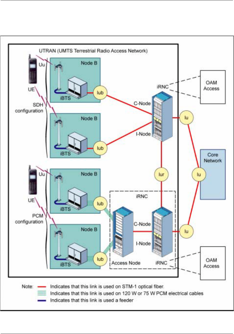
Nortel Networks UTRAN solution
iRNC
The iRNC is the e--mobility Internet RNC. It is the 3GPP--compliant UMTS RNC developed by Nortel
Networks. The generic term iRNC is used throughout this document to designate the e--mobility Internet
RNC.
The iRNC allows mobility between UMTS and GSM networks.
The main functions of the iRNC are to control and manage:
the RAN (Radio Access Network)
the signaling between the different CN elements and the RNS
the node Bs
the radio resources of the corresponding node Bs.
The iRNC houses the following cabinets:
the C--Node (Control Node)
The C--Node is an ATM--based engine that support UMTS call processing and signaling as well as
OAM of both the RNC and the node Bs.
the I--Node (Interface Node)
This isbasedonPassport 15000.Itisahigh--capacity ATMswitch, inchargeoftheconnectivity(User
Plane) of the iRNC.
the Access Node
ThisoptionalcabinetisusedforaPCMxconfiguration.ItisaPassport7480switch.Themainfunction
of the Access Node is to convert the STM1 links into PCM links and vice versa.
iBTS
The iBTS is the e--mobility Internet BTS. It is the 3GPP--compliant UMTS node developed by Nortel
Networks. The generic term iBTS is used throughout this document to designate the e--mobility Internet
BTS.
The following types of iBTS are available:
e--mobility Internet BTS ---- indoor version (600 and 700)
e--mobility Internet BTS ---- outdoor version
Nortel Networks Confidential
8
UMT/DCL/DD/0002
411--8111--905 Preliminary 01.06/EN october 2001 UMTS01
Figure 2
UTRAN architecture

Nortel Networks Confidential 9
About the iBTS
iBTS description
Introduction
A node B is a logical node responsible for radio transmission/reception in one or more cells to/from the
User Equipement.
A node B provides the following interfaces:
the Iub interface towards the iRNC
the Uu interface towards the User Equipment (UE)
A node B may consists of one or several iBTSs.
The iBTS product is a line of products that cover different customers requirements:
the outdoor BTS product (iBTS outdoor)
the indoor BTS product (iBTS indoor 600 and iBTS indoor 700)
The main functions of the iBTS are the following:
to provide the means of communication between a UE and a network via Transport Channels.
toprovidetheUEwithsomephysicallayerchannelswhicharenecessarytosynchronizethedownlink
and also to perform cell selection/reselection and handover preparation
to provide measurement information to the RNC for radio resource management (handover, power
control)
TheiBTS ismodular indesignfor easynetworkgrowthandflexibility,tomanagediversetrafficdemands.
Common modules are used to grow the iBTS to increase capacity as demand requires. The increase
of capacity is provided via the simple addition of modules, as opposed tothe entire addition of cabinets.
iBTS location
The iBTS outdoor can be installed on two types of site:
on terraces of buildings
at ground level
The iBTS indoor can be installed inside premises, if an air exchanger is provided in these premises.
iBTSs are connected to their controller (iRNC) in a star configuration.

Nortel Networks Confidential
10
UMT/DCL/DD/0002
411--8111--905 Preliminary 01.06/EN october 2001 UMTS01
iBTS operational features
The main characteristics of the iBTS are the following:
no need for an extra site cabinet (iBTS outdoor) for user space and batteries
easy installation and commissioning
a flexible product: possible growth from low to high capacity without any additional cabinets
front access only
PCM internal protection
most common modules between the iBTS outdoor and the iBTS indoor
iBTS indoor powered in dc or ac
The iBTS is a low capacity solution that can grow in a modular way to full capacity.
The iBTS supports the following functions:
radio access and modem (modulation/demodulation, frequency up/down--conversion, amplification)
call processing (channel set--up and management for both common and dedicated channels, cell
management, power control, handover and measurement)
configuration and supervision
synchronization (to retrieve a highly stable radio frequency from either the network interface)

Nortel Networks Confidential 11
About the iBTS
iBTS tools and utilities
TheiBTS hastwomainmaintenance tools: theOAMAccess(Operation, AdministrationandMaintenance)and
the TIL (Terminal for Local Installation).
The Operation and Maintenance center for Node B is responsible for the configuring and supervising
functions. The main OAM functions are the following:
operation and maintenance
alarm management
configuration and supervision
performance monitoring
The TIL is composed of alaptop PC(with Webbrowser) connectedto the iBTS. The TIL is used toinstall
and commission the iBTS.
The TIL performs the following:
It displays the existing hardware of the iBTS product.
It automatically displays new hardware.
It provides basic maintenance and test capabilities for all iBTS modules.
It allows users to save reports (alarm, test reports) on the PC.
It retrieves the hardware and software module configuration.
It downloads new software of iBTS modules.
Nortel Networks Confidential
12
UMT/DCL/DD/0002
411--8111--905 Preliminary 01.06/EN october 2001 UMTS01
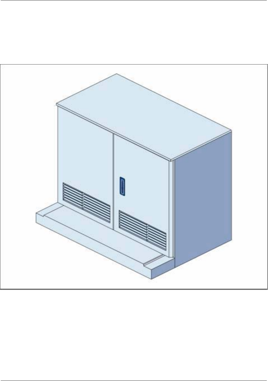
Presentation of the iBTS outdoor
The iBTS outdoor is a single cabinet closed by two doors.
Figure 3
Outside view (iBTS outdoor)
Nortel Networks Confidential 13
About the iBTS
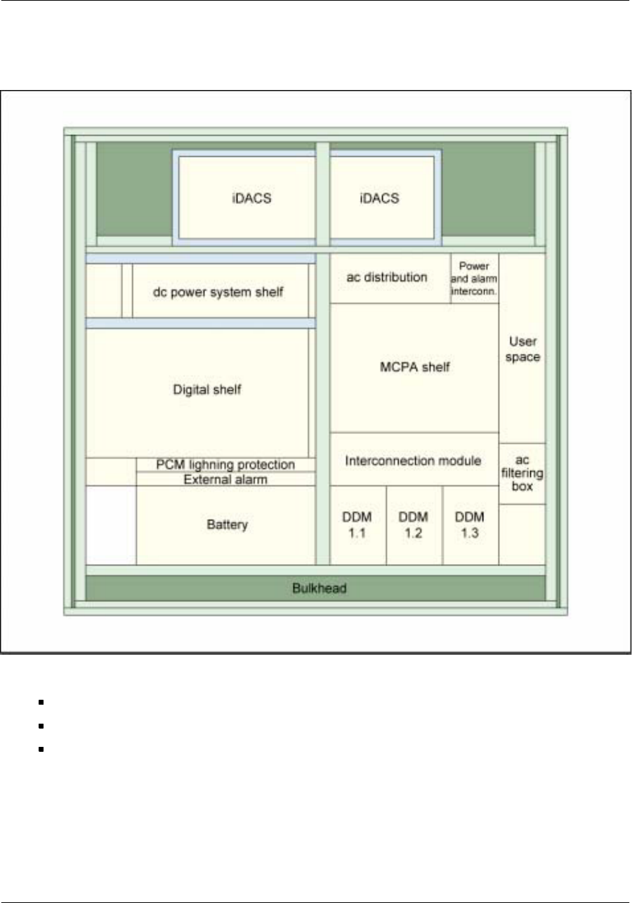
Figure 4
Inside view (iBTS outdoor)
The cabinet is divided into:
the iDACS (internet Direct Ambient Cooling System) which is the cooling unit of the cabinet
the main compartment
the bulkhead which allows cable connection and lightning protection

Nortel Networks Confidential
14
UMT/DCL/DD/0002
411--8111--905 Preliminary 01.06/EN october 2001 UMTS01
The main compartment is divided into two parts:
the left part which includes:
xthe dc power system shelf: the dc distribution module, the SPCM (Single Power Control Module),
the rectifiers (up to seven)
xthe digital shelf
xthe battery system
the right part which includes:
xthe ac distribution module
xthe RF block
xthe user space and its ICO
xthe interconnection module
xthe ac filtering box
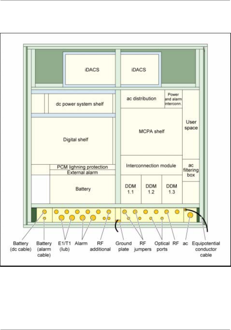
Nortel Networks Confidential 15
About the iBTS
Figure 5
Bulkhead front view (iBTS outdoor)

Nortel Networks Confidential 21
About the iBTS
Description of the digital shelf of the iBTS
The digital shelf houses all the digital modules of the iBTS. The digital shelf is common to theiBTS indoor 700
and the iBTS outdoor and houses up to 12modules. These modules share ten slots in the iBTS indoor cabinet.
Backplane functionalities
The backplane boardis partof thedigital shelf. It isin chargeof supporting allinternallinks andelectrical
interfaces between the modules of the digital shelf.
All modules and cables carrying external signals plug into connectors mounted on the backplane board.
The backplane board accomodates several high speed signals up to 1.3 Gbit/s. It supports --48 V or +
24 V power supply.
The backplane provides Inter--module connections and --48 V dc.
Physical description of the digital shelf
“T bar” rails are used in the digital shelf to guide the modules during insertion and removal operations.
The digital shelf houses up to 10 modules (iBTS indoor 600) or 12 modules (iBTS outdoor and iBTS
indoor 700), in complete configuration (for future versions), with flexible positions:
CCM (Core Control Module)
CEM (Channel Element Module)
TRM (Transceiver Receiver Module)
GPSAM (GPS interface and Alarm Module)
All the modules are removable and are 50--mm wide.
All the cables providing interconnection between the modules are mounted at the front of them.
Nortel Networks Confidential
22
UMT/DCL/DD/0002
411--8111--905 Preliminary 01.06/EN october 2001 UMTS01
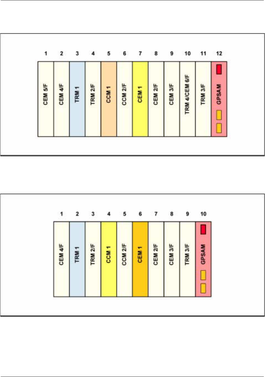
Figure 11
Front view of the digital shelf (iBTS outdoor and iBTS indoor 700)
F=Filler: module available for future versions
Figure 12
Front view of the digital shelf (iBTS indoor 600)
F=Filler: module available for future versions
Nortel Networks Confidential 23
About the iBTS
Description of the RF block of the iBTS
The RF block contains the MCPA and the DDM modules. The RF block is common to the iBTS indoor and the
iBTS outdoor. The number of modules depends on the iBTS configuration.
Physical description
The RF block contains the RF modules:
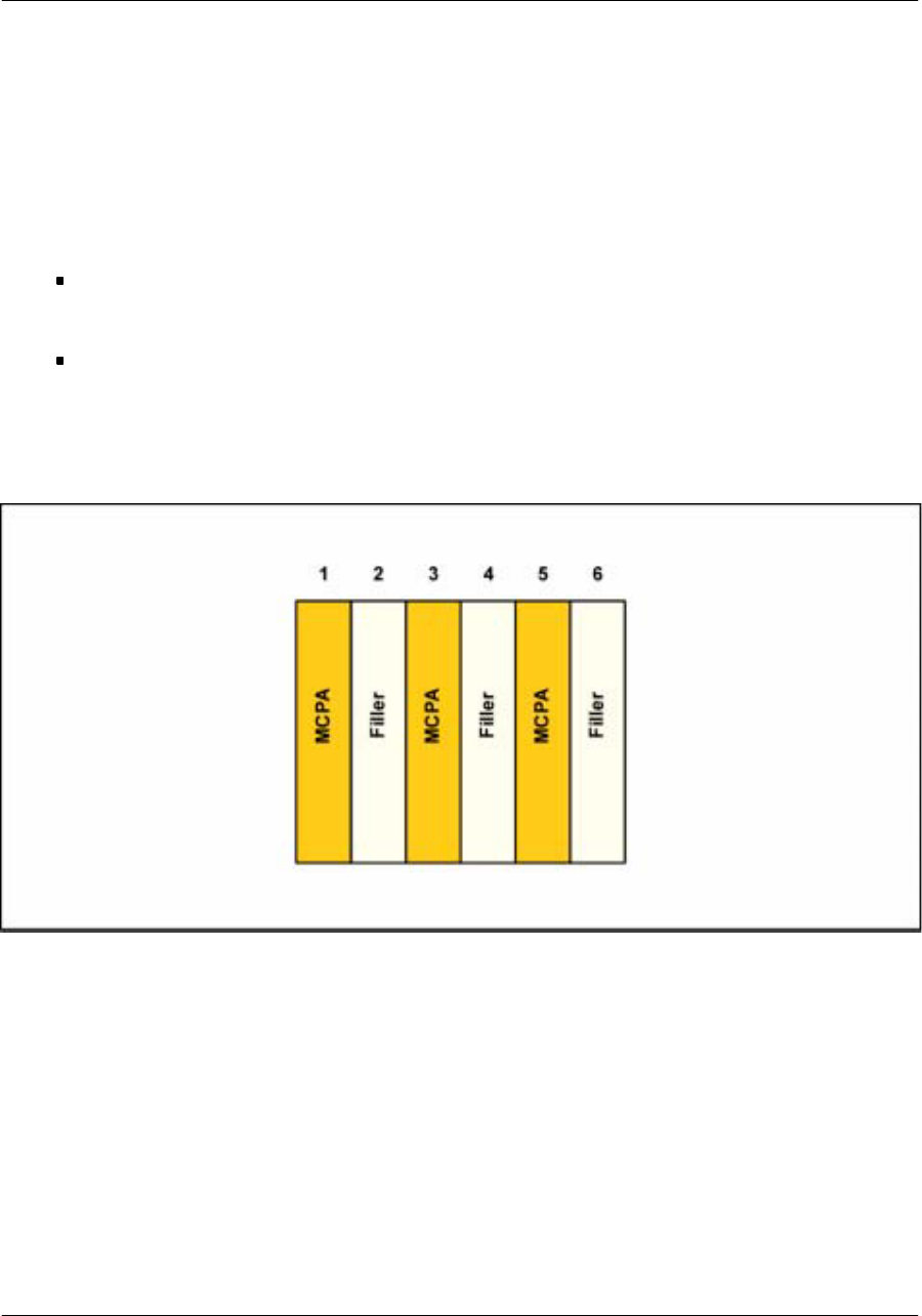
One MCPA shelf that contains six slots. In the three MCPAs configuration, these MCPAs are housed
in slots 1, 3, and 5. There is no electrical backplane in the MCPA shelf: all the interconnection cables
are mounted at the front of the MCPAs.
One DDM shelf that contains three DDMs.
All the cables providing interconnection between the modules are mounted at the front of them.
Figure 13
Front view of the MCPA shelf

Nortel Networks Confidential
24
UMT/DCL/DD/0002
411--8111--905 Preliminary 01.06/EN october 2001 UMTS01
Configuration rules of the iBTS
The iBTS has the following characteristics:
one mode of operation: STSR
one frequency carrier
Antenna configuration
The iBTS can be equipped with:
two antennas for single--sector configuration
four antennas for bi--sector configuration
six antennas for three--sectors configuration
Frequency carriers
The iBTS supports multi--carriers configuration and allows 5 MHz operation in the STSR configuration.

Nortel Networks Confidential 25
About the iBTS
STSR configuration
STSR configuration stands for Sectorial Transmit Sectorial Receive. It is the standard three--sector
configuration. The iBTS is logically declared at the iRNC as three cells. The user equipment reports
measurements for the three sectors and softer handover is controlled by the network.
The power allocation in STSR is independant across sectors.
The iBTS supports the STSR1 configuration: one carrier per sector.
The STSR1 configuration requires:
one TRM which allows the reception of up to 6 signals (3x2)
one CCM
one CEM which is configured for three sectors x two carriers
three MCPAs (one per sector)
three DDMs (one per sector)
iBTS outdoor
The outdoor cabinet equipment layout follows the rules described in the following table:
4
5
W
c
o
n
f
i
g
u
r
a
t
i
o
n
Digital shelf RF shelf Power
45--
W
con
f
i
gurat
i
on CCM TRM CEM GPSAM MCPA DDM Rectifier
STSR1 1 1 1 1 3 3 4+1
iBTS indoor
The indoor cabinet equipment layout follows the rules described in the following table:
Digital shelf RF shelf Power
Configuration CCM TRM CEM GPSAM MCPA DDM Rectifier
plinth
STSR1 1 1 1 1 3 3 7+1

Nortel Networks Confidential
26
UMT/DCL/DD/0002
411--8111--905 Preliminary 01.06/EN october 2001 UMTS01
iBTS physical characteristics
This section gives the physical characteristics of the iBTS cabinet.
iBTS outdoor
Dimension and weight
width: 1,35 m
depth: 0,7 m
height: 1,3 m
weight :
xfully equipped: 520 kg
xin STSR1 configuration with internal batteries: 426,4 kg
iBTS indoor
Dimension and weight of the iBTS indoor 600
Width: 0,6 m
Depth: 0,6 m
Height:1,6 m
Weight: 260 kg (fully equipped)
Dimension and weight of the iBTS indoor 700
Width: 0,7 m
Depth: 0,6 m
Height:1,6 m
Weight: 325,5 kg (fully equipped)
Dimension and weight of the iBTS indoor 700 with ac plinth
Width: 0,7 m
Depth: 0,6 m
Height: 2 m
Weight: 513,5 kg (fully equipped)

Nortel Networks Confidential 33
About the iBTS
TRM (Tranceiver Receiver Module) description
The TRM is located in the iBTS digital shelf. In the complete configuration, for future versions, the highest
number of TRMs is four. The present version contains only one TRM.
Nortel Networks Confidential
34
UMT/DCL/DD/0002
411--8111--905 Preliminary 01.06/EN october 2001 UMTS01
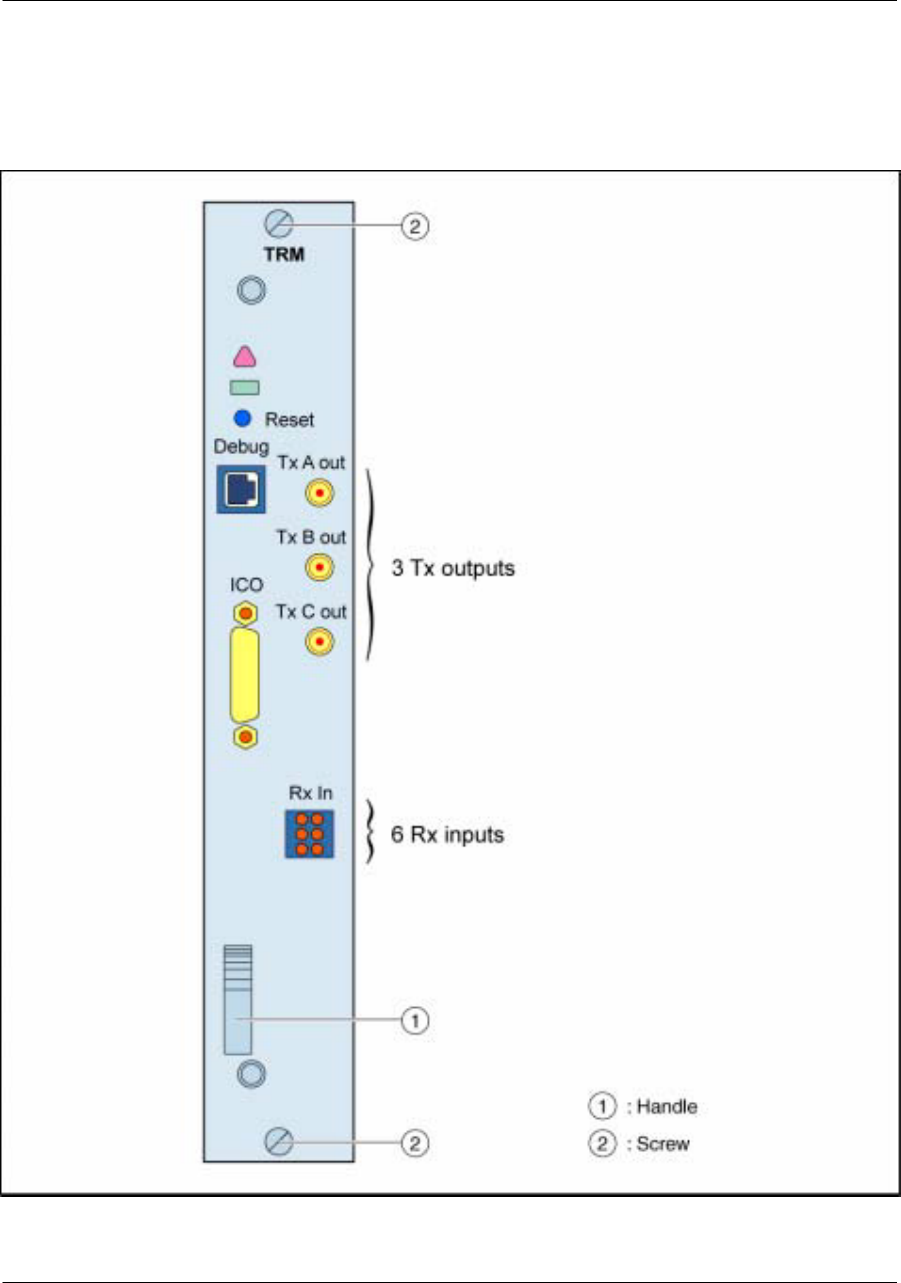
TRM hardware description
Figure 17
Front view of the TRM

Nortel Networks Confidential 35
About the iBTS
Front panel description
The front panel of the TRM module has two corporate leds indicating the TRM status:
Green
rectangular
LED
Red triangular
LED Status
OFF OFF Sleep, unpowered or not inserted
ON ON Power up self--test underway
ON OFF Module should not be removed
ON BLINK Module is partially faulty
OFF ON Module may be removed, alarm state, BISTs NOK
OFF BLINK Module is waiting for Boot
The front panel also has:
one “Debug” Ethernet connector (RJ--45 type connector)
one “Reset” button accessible through an eye in the front panel
three RF outputs (to MCPAs): “Tx A out”, “Tx B out”, and “Tx C out” (SMA connectors)
six RF inputs (from DDMs): “Rx in” (radial connectors)
one interconnection connector for digital communication between RF modules (D--sub connector)
Haardware composition
The TRM is made of two boards.
one dTRM board, including:
x6 Tx channelizers
x3 Rx channelizers
one rTRM board, including:
x3 wideband transmitters
x3 dual 5 MHz receivers
Nortel Networks Confidential
36
UMT/DCL/DD/0002
411--8111--905 Preliminary 01.06/EN october 2001 UMTS01
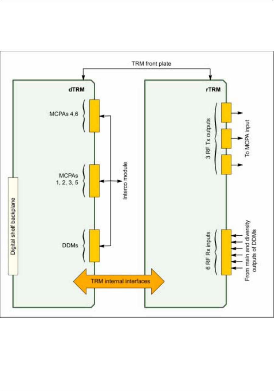
TRM interfaces
Figure 18
TRM interfaces
Note: This figure describes the complete configuration (available for future versions)

Nortel Networks Confidential 37
About the iBTS
Internal interfaces
The internal interfaces are the signals exchanged between the rTRM and the dTRM boards.
The samples are sent to the rTRM board and are converted into an analog signal. In the opposite
direction,therTRMboarddigitallyconvertsthesixreceivedsignalsandsendstheresultingsampleflows
to the dTRM board.
External interfaces
The external interfaces are the following:
digital shelf backplane interface: based on the dTRM board
CCM interface: based on the common HSSL interface
Nortel Networks Confidential
38
UMT/DCL/DD/0002
411--8111--905 Preliminary 01.06/EN october 2001 UMTS01
CCM (Core Control Module) description
The CCM is located in the iBTS digital shelf. In the complete configuration, for future versions, the highest
number of CCMs is two. The present version contains only one CCM.
CCM hardware description
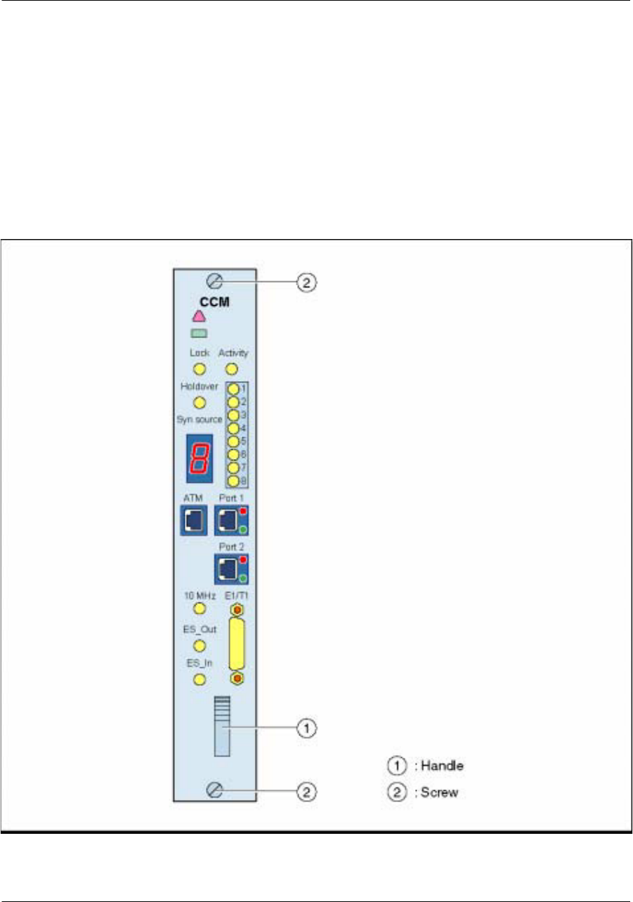
Figure 19
Front view of the CCM

Nortel Networks Confidential 39
About the iBTS
Front panel description
The connectors of the front panel are the following:
one “ATM” test port (RJ--45 connector)
two “Port 1” and“Port 2” Ethernet ports (10/100 Base Tand 10Base T connectors) used for Ethernet
access and TIL connection
one “E1/T1” connector (44--pin D--sub female connector) used for E1/T1 connection
three timing reference ports (SMB connector) for iBTS commissioning labelled “10 MHz”, “ES Out”
(Even Second Output), and “ES In” (Even Second Input)
The leds on the front panel are the following:
two corporate leds indicating the CCM status:
Green
rectangular
LED
Red triangular
LED Status
OFF OFF BISTs results NOK, Sleep, unpowered or not inserted
ON ON Power up self--test underway
ON OFF Module should not be removed
ON BLINK Module is partially faulty
OFF ON Module may be removed, alarm state
OFF BLINK Module is waiting for Boot
BLINKING OFF, ON, or
BLINK Downloading in progress
two synchronization status indicators: “Lock” (green led) and “Holdover” (yellow led)
one “Activity” led which indicates the module status
eight PCM status leds which indicate if the PCM link is OK (green led), if the PCM is in alarm (red
led), or if the PCM is in tri--state (amber led)
The CCM front panel also has a display witch indicates the synchronization source. The dot on the right
of the indication allows to differentiate the synchronized state.
Display
1,2,3,4,5,6,7, 8 PCM number
aorb GPS 0 or GPS 1
Aactive CCM
Eeven second external input
Hholdover mode

Nortel Networks Confidential
40
UMT/DCL/DD/0002
411--8111--905 Preliminary 01.06/EN october 2001 UMTS01
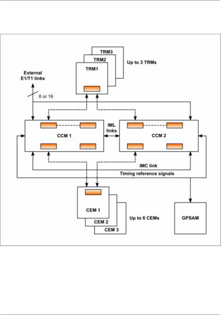
CCM interfaces
Signal interfaces
One CCM supports up to three wide--band carriers with transmit and receive diversity in a tri--sectored
carrier configuration.
Each CCM is linked with the CEM and TRM by a point--to--point HSSL connection.
The two CCMs are linked by two signals:
the IML ATM links: 155 Mbit/s
the IMC links: 10 Mbit/s
The following figure shows the different interfaces of the CCM.
Nortel Networks Confidential 41
About the iBTS
Figure 20
Data flow of the CCM
Note: This figure describes the complete configuration (available for future versions).

Nortel Networks Confidential
42
UMT/DCL/DD/0002
411--8111--905 Preliminary 01.06/EN october 2001 UMTS01
GPSAM (GPS and Alarm Module) description
The GPSAM is located on the right side of the iBTS digital shelf.
Nortel Networks Confidential 43
About the iBTS
Hardware description
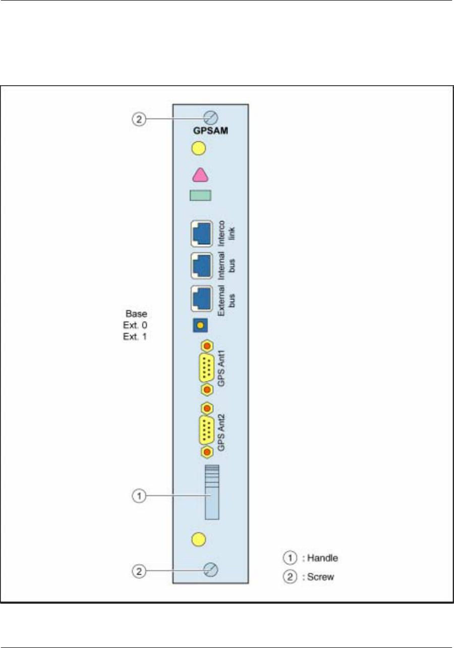
Figure 21
Front view of the GPSAM

Nortel Networks Confidential
44
UMT/DCL/DD/0002
411--8111--905 Preliminary 01.06/EN october 2001 UMTS01
The GPSAM is a single module located on the right--hand side of the iBTS digital shelf.
Front panel description
The front panel of the GPSAM module has:
one ”interco link” (RJ--45 type connector) connector used to connect the interconnection module in
case of an extension cabinet
one ”Internal bus” (RJ--45 type connector) connector used for the iBTS internal bus link
one ”External bus” (RJ--45 type connector) connector used for the iBTS external bus link
one three positions switch: “Base”, “Ext. 0”, and “ Ext. 1” which indicates in which cabinet (base
cabinet, first extension cabinet, or second extension cabinet) the digital boards are inserted.
two “GPS Ant” 15--pin D--sub female connectors for the optional connection of GPS smart receivers,
not used in this product release.
Leds
The front panel of the GPSAM module has two corporate leds indicating the GPSAM status:
Green
rectangular
LED
Red triangular
LED Status
OFF OFF sleep, unpowered or not inserted
ON ON power up self--test underway
ON OFF operational module
OFF ON alarm state
TRM interface
Power supply
The GPSAM is powered with external --48 V dc.
The maximum power is estimated at 20 W.

Nortel Networks Confidential
54
UMT/DCL/DD/0002
411--8111--905 Preliminary 01.06/EN october 2001 UMTS01
Hardware description of the RF block
This section describes the modules of the RF block:
DDM (Dual Duplexer Module)
MCPA (Multi Carrier Power Amplifier)
optional TMA (Tower Mashead Amplifier)
Nortel Networks Confidential 55
About the iBTS
DDM (Dual Duplexer Module)
The DDMs are located in the DDM shelf which houses three DDMs. The DDM is used in outdoor or indoor
configurations.
Hardware description
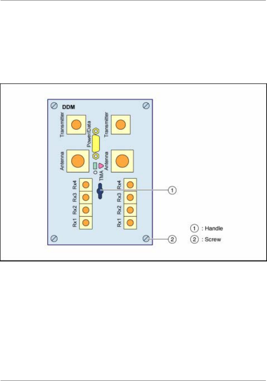
Figure 30
Front view of the DDM

Nortel Networks Confidential
56
UMT/DCL/DD/0002
411--8111--905 Preliminary 01.06/EN october 2001 UMTS01
Front panel description
The front panel of the DDM has two corporate leds indicating the DDM status:
Green
rectangular
LED
Red triangular
LED Status
OFF OFF Sleep, unpowered or not inserted
ON ON Power up self--test underway
ON OFF Module should not be removed
ON BLINK Module is partially faulty
OFF ON Module may be removed, alarm state
OFF BLINK Module is waiting for Boot
One two position switch indicates the functioning mode of the DDM: mode with TMA or mode without
TMA.
Hardware composition
The design of the DDM allows an easy transition from receive diversity to transmit diversity.
TheDDMconsistsofadouble--duplexerLNAchain:oneforthemainpath,theotherforthediversitypath.
The DDM provides the following functions:
isolation between transmit and receive signals
filtering of the transmitted and received signals to reduce interfering signals
DDM interfaces
All DDM interfaces are located on the front panel.
There are three types of interface:
RF interface
digital interface
power supply interface
RF interface
Radio interfaces are coaxial cables:
two “Antenna” ports, main & diversity (7/16 female connector)
two “Transmitter” inputs (N female connector)
eight “Rx” outputs (SMA female connector)

Nortel Networks Confidential 57
About the iBTS
Digital interface
The corresponding connector is a 15--pin D--sub female connector. The digital interface allows
communication with the TRM. TRM software is able to detect if a DDM is physically connected to this
interface.
Power supply
The DDM is power supplied by --48 V dc.
Detailed functional description
The main functions of the DDM are the following:
one single antenna port for the Tx and Rx paths
dedicated isolation between Tx and Rx frequency bands
Tx and Rx out--of--band filtering
low--noise amplification in Rx frequency bands and signal splitting into four local outputs
VSWR alarm monitoring capability
TMA dc supplying
TMA alarm monitoring
suppression of transient voltage suppression from the antenna port following external lightning
protection
inventory capability
active function monitoring
Nortel Networks Confidential
58
UMT/DCL/DD/0002
411--8111--905 Preliminary 01.06/EN october 2001 UMTS01
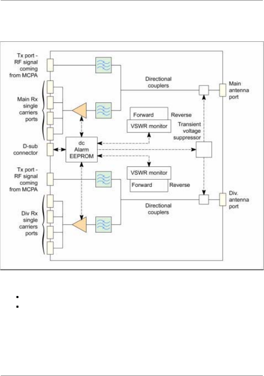
Figure 31
DDM block diagram
The DDM includes two dc/dc converters dedicated to the main and diversity branches:
one converter supplies TMA and DDM main
the other converter supplies TMA and DDM diversity
Two VSWR monitors are also included in the DDM: they are able to monitor RF matching between the
antenna and the iBTS.
Nortel Networks Confidential 59
About the iBTS
MCPA (Multi Carrier Power Amplifier)
The MCPAs are located in the MCPA shelf which houses up to 6 MCPAs. The present version of the iBTS
contains three MCPAs.
Hardware description
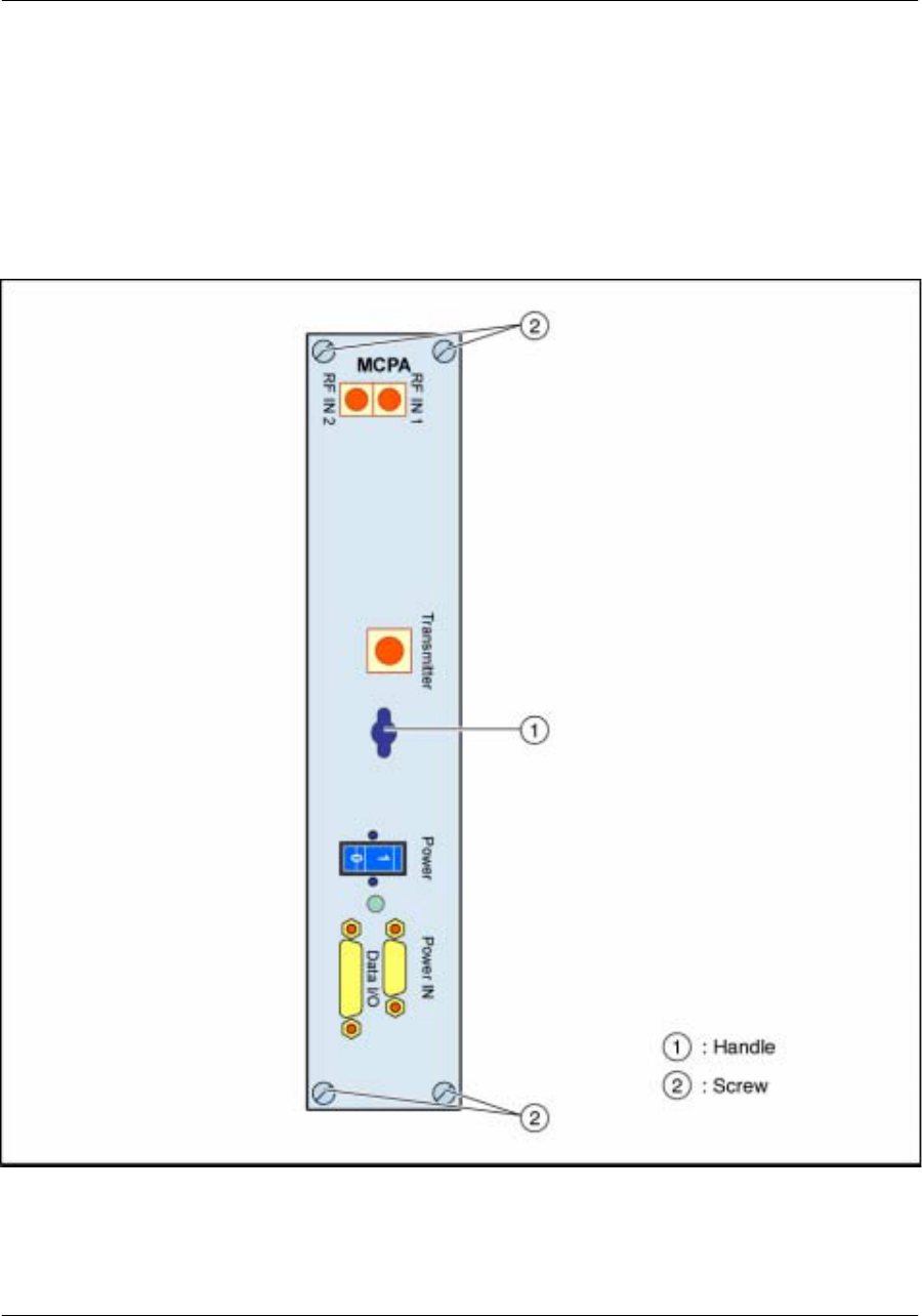
Figure 32
Front view of the MCPA module
The front panel of the MCPA module has one led indicating if the MCPA module is operational: the led
is green if the module is operational and red if it is not operational.

Nortel Networks Confidential
60
UMT/DCL/DD/0002
411--8111--905 Preliminary 01.06/EN october 2001 UMTS01
The front panel also has one on/off power switch to switch off the input dc supply.
All external connections are connected to the MCPA through the front panel.
MCPA interface
Radio interfaces
The front panel has two “RF IN” connectors (SMA 50 :female connector) and one “Transmitter”
connector (N female type connector) for RF ouput for radio interface.
Interconnection interfaces
The front panel has one “Data I/O” connector for digital information exchange with the TRM (25--pins
D--sub connector).
Power supply interface
The front panel has one “Power IN” connector (3--pin 3W3 connector).
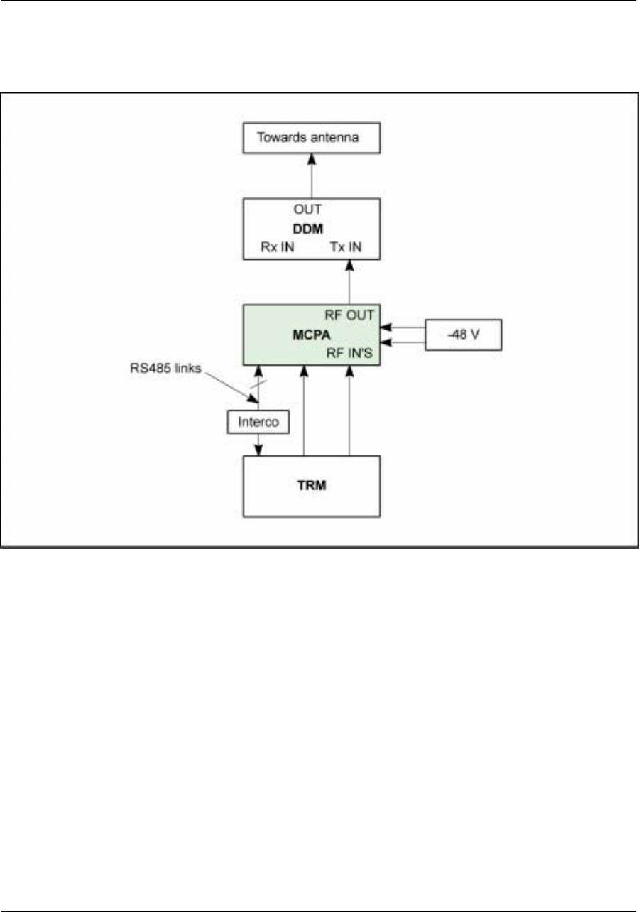
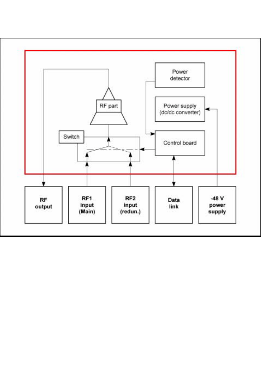
MCPA functional description
The MCPA module provides downlink signal amplification. The aim of the MCPA is to amplify the RF
signal delivered by the TRM.
The MCPA is connected to the antenna through a duplexer for sectorial configurations.
The MCPAs handle up to 1 carrier (5 MHz operation).
The MCPA mode of operation is 45 W.
Nortel Networks Confidential 61
About the iBTS
Figure 33
Functional description of an MCPA (only one sector)
Nortel Networks Confidential
62
UMT/DCL/DD/0002
411--8111--905 Preliminary 01.06/EN october 2001 UMTS01
Figure 34
MCPA functional block diagram
Nortel Networks Confidential 63
About the iBTS
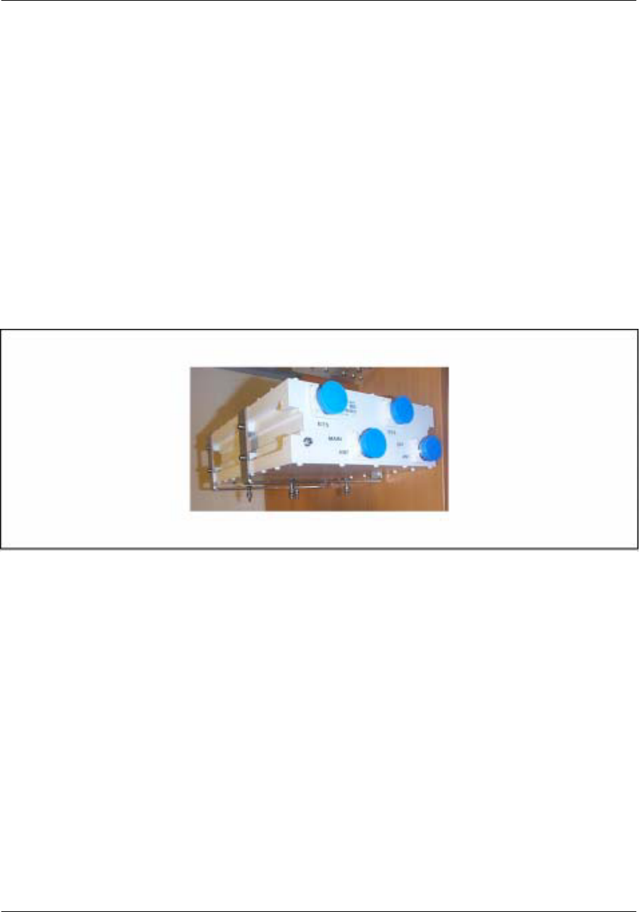
TMA (Tower Mounted Amplifier)
In case the cable length between the iBTS cabinet and the antenna is high, an optional TMA is mounted as
near as possible from the antenna system in order to improve sensibility.
General description
The TMA module allows to decrease the overall noise figure of the system by amplifying the receive
signal.The TMA module is a LNA (Low Noise Amplifier). It amplifies the received RF signal in the early
stages of the reception path before going through the feeders. The TMA enables two single antennas
(main and diversity) to be used for up--link and down--link.
The TMA is powered from the DDMs through the RF coaxial cable.
Figure 35
TMA outside view
AllexternalconnectionsarelocatedatthebottomoftheTMAmodule.TheRF connectorsare 7/16emale
connectors.
Nortel Networks Confidential
64
UMT/DCL/DD/0002
411--8111--905 Preliminary 01.06/EN october 2001 UMTS01
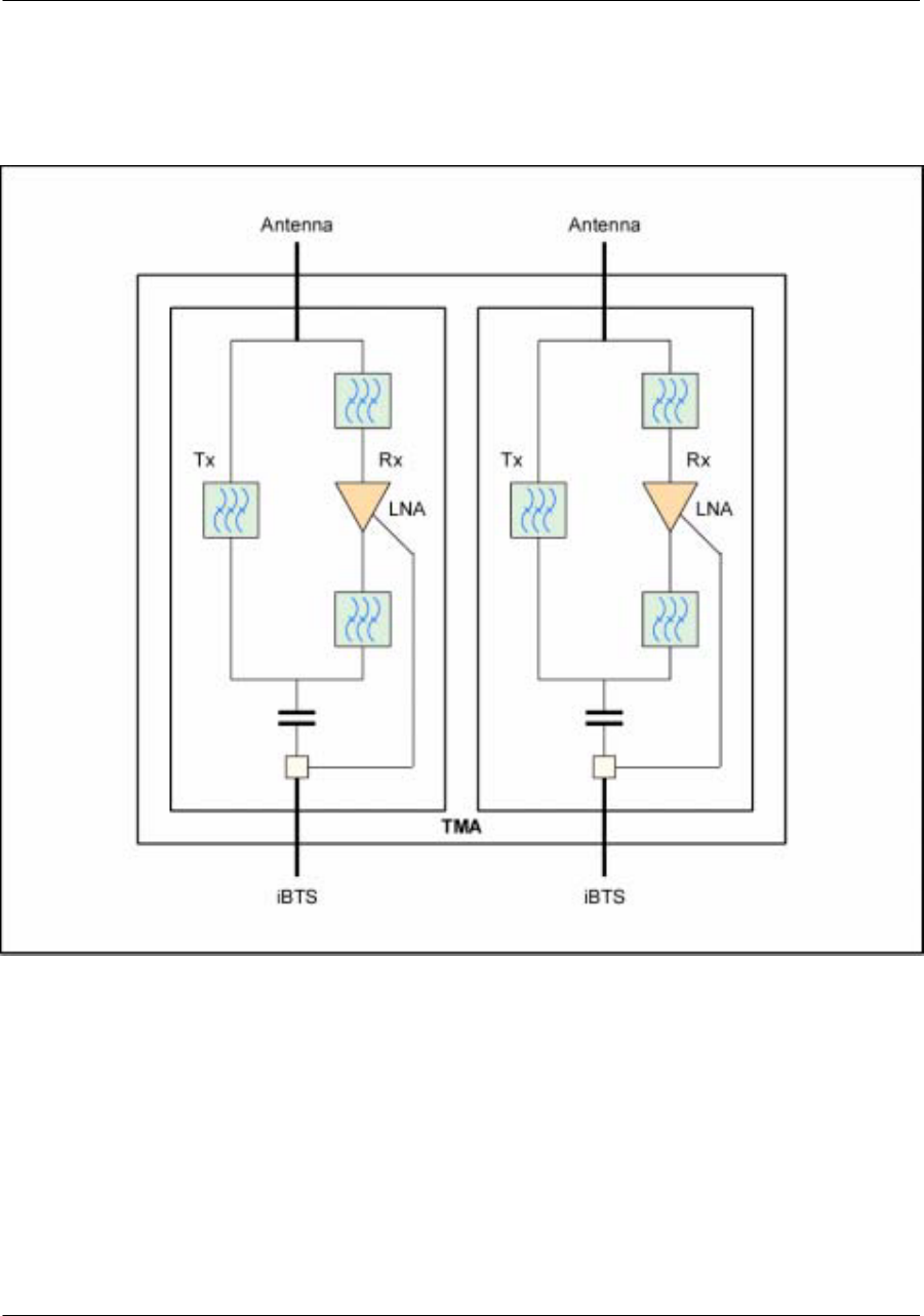
Figure 36
TMA block diagram
Protection
Data and RF lightning protection is performed at the iBTS connectors.
Protecting cups provide the TMA connectors with mechanical and environmental protection.
The DDMs monitor TMA alarms and report them to the digital shelf through I2C connection.
Nortel Networks Confidential 65
About the iBTS
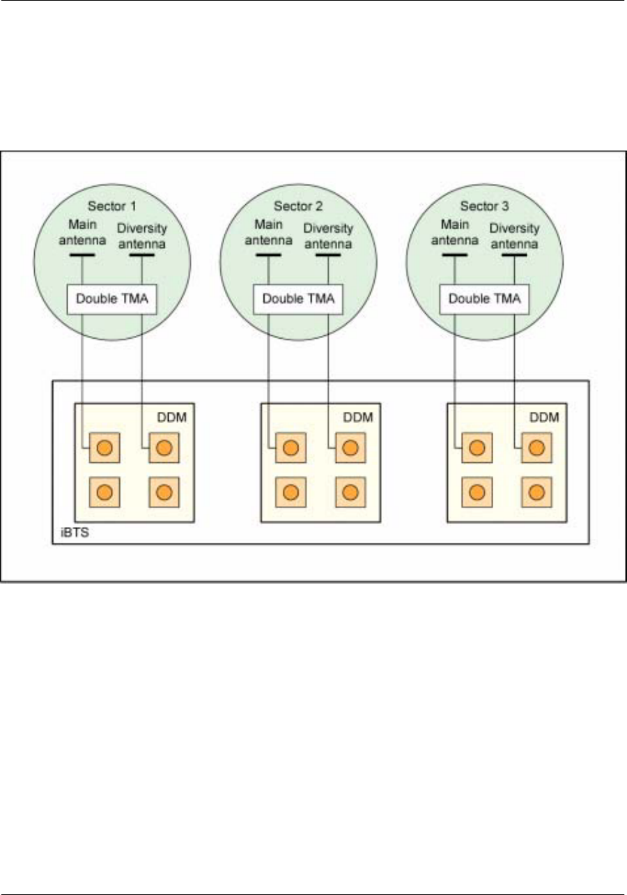
TMA system overview
The optional TMA is a double UMTS TMA module.
Figure 37
Double TMA system overview
Nortel Networks Confidential 107
About the iBTS
TRM functional description
Generalities
The TRM contains the transmit/receive circuitry for three transmit chains and six receive chains. It
performs:
modulation and demodulation
clock recovery and synchronization
digital--analog and analog--digital conversion
up and down frequency conversion
These functions are performed with the digital and radio boards.
The functional block diagram of the TRM is shown in the following figure:
Figure 62
Functional block diagram of the TRM
Note: This figure describes the complete configuration (available for future versions).

Nortel Networks Confidential
108
UMT/DCL/DD/0002
411--8111--905 Preliminary 01.06/EN october 2001 UMTS01
Digital TRM board (dTRM)
The digital board functions are the following:
reception of (up to) six transmit signals from the CCM
reception of the six signals from the antennas (main and diversity)
recovery and distribution of the clock
control and monitoring of the radio modules (TRX, MCPA, DDM)
supply voltages for radio board
Radio TRM board (rTRM)
The radio board performs the following functions:
in the downlink path
xdigital--to--analog conversion
xfrequency up--conversion
xamplification
in the uplink path
xfrequency down--conversion
xanalog--to--digital conversion
The rTRM board consists of three transmit chains and three dual receive chains.
Detailed functional description
General
Downlink path
The dTRM board receives up to six signals from the CCM. These downlink samples are transferred to
theTxchannelizers.Thechannelizersperformchiplevelmodulation,peakpowerreduction,filtering,and
then deliver the signals (three max) to the D/A converters of the rTRM board.
In the analog domain, the digital signals are transformed into RF signals through D/A conversion,
modulation, filtering/amplification and translation operations. The final RF signals have the appropriate
level to drive the MCPA.
The total transmitted power is proportional to the data rate of the codes and the number of these codes
(communications). A power control adjusts each RF signal to optimise the total interference level noise
between the iBTS and the user equipment.
Uplink branch
The uplink branch handles three pair--received signals (main and diversity) coming from the antenna via
acouplingsystemwhichseparates transmissionfromreception.Thesesignalsarefiltered,amplificated,
demodulated, A/D converted and then transmitted to the Rx channelizers in the digital domain.
Nortel Networks Confidential 109
About the iBTS
Thereceivechannelizerreceives thesixA/Dconvertersignals.It processesthe dataandtransmitsthem
to the CCM.
Other functions
The TRM also performs the clock generation and recovery operation. The clock is recovered from the
link with the CCM and sent to the rTRM board. This board generates the clock signals for the A/D
converters of the receiver branch and the A/D converters of the transmitter branch.
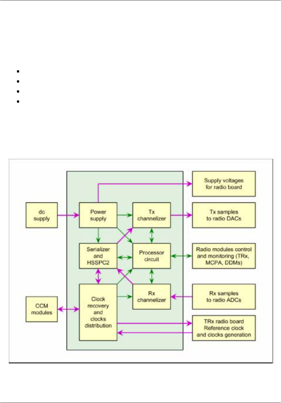
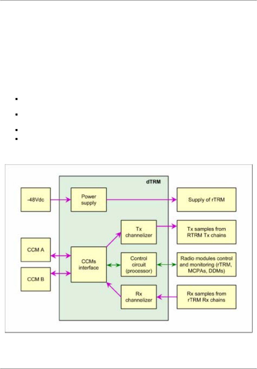
dTRM board functional description
The functions of the dTRM board are the following:
It receives the data samples from the CCM, performs data shaping processing on them, then drives
the three transmit chains with the resulting data samples.
It receives the data samples from the six TRM receive chains, performs data shaping processing on
them, then sends the resulting data samples to the CCM.
It performs OAM operations on the TRM, the MCPAs and the DDMs.
It supplies the rTRM board.
Figure 63
Block diagram of the dTRM board
Note: This figure describes the complete configuration (available for future versions).
Nortel Networks Confidential
110
UMT/DCL/DD/0002
411--8111--905 Preliminary 01.06/EN october 2001 UMTS01
The dTRM Rx and Tx data processing functions are mainly implemented in the processor of the dTRM
and in the channelizers.
The dTRM board includes six TX channelizers. Each of them is able to support one UMTS channel, and
they can be put in cascade. The transmit possibility is three 3--carrier signals.
On the Rx side, the dTRM board allows the reception of up to six single carrier signals. It can implement
one of the following solutions:
reception of one carrier from three sectors
reception of three carriers from an omni cell
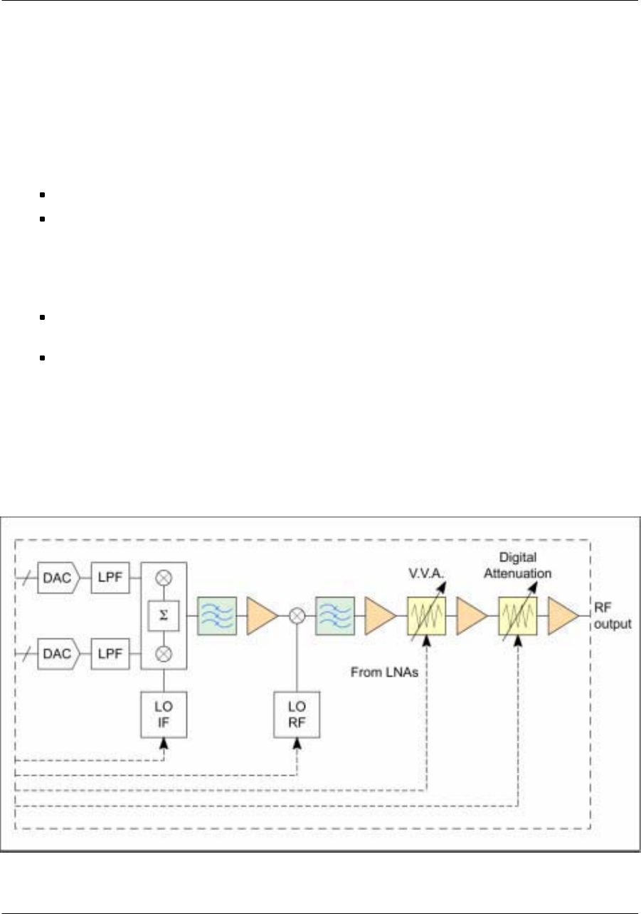
rTRM board functional description
The functions of the rTRM board are the following:
It receives digital samples from the dTRM, converts them into analog signals, upconverts to radio
UMTS frequency, filters the signal and adjusts the output power for the MCPA input.
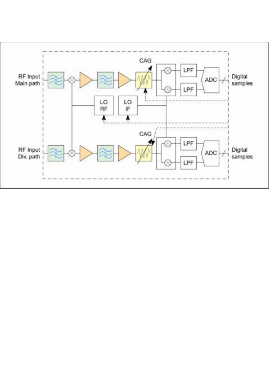
It filters the input signal, downconverts, filters and samples it, then transmits the digital samples to
the dTRM board.
The rTRM board consists of three transmit paths at the same radio frequency and three main/diversity
paths that can be tuned to three different frequencies.
Figure 64
Block diagram of the rTRM transmit part
Nortel Networks Confidential 111
About the iBTS
Figure 65
Block diagram of the rTRM receive part

Nortel Networks Confidential
116
UMT/DCL/DD/0002
411--8111--905 Preliminary 01.06/EN october 2001 UMTS01
Radio interface
The radio interface consists of six RF ports which correspond to the connection to main and diversity antenna
for three sectors.
The frequency--dependent DDM module is compatible with the standard UMTS bands:
2110--2170 MHz for downlink
1920--1980 MHz for uplink
The impedance of the radio interface is 50 :.
Radio cabling
7/16 connectors are located:
at the bottom of the cabinet for the iBTS outdoor (bulkhead)
at the top of the cabinet for the iBTS indoor
The antenna feeders arrive as close as possible to the iBTS cabinet. The interconnection between the
feeders and the jumpers is done outside the iBTS.
The number of feeders depends on the configuration type.