Avaya 1 3 Users Manual 1c_install
1.3 to the manual f1a19aa4-047a-4290-8e69-68c5bd42743c
2014-12-13
: Avaya Avaya-1-3-Users-Manual-122046 avaya-1-3-users-manual-122046 avaya pdf
Open the PDF directly: View PDF ![]() .
.
Page Count: 256 [warning: Documents this large are best viewed by clicking the View PDF Link!]
- Avaya Computer Telephony
- Release 1.3
- Installation Guide
- Contents
- Preface - About This Document
- Chapter 1: Learning About Avaya Computer Telephony
- Chapter 2: Administering the Switch
- Chapter 3: Installing Avaya Computer Telephony Server Software
- Planning Your Installation
- Guidelines for Upgrading Avaya Computer Telephony
- Specialized Installations
- Before You Install the Avaya Computer Telephony Server Software
- Avaya Computer Telephony Installation Guidelines
- Procedure for Initial, Default Installation of Avaya Computer Telephony Server Software
- Perform Initial Restart
- Desktop Components
- Basic Maintenance Tasks
- Chapter 4: Installing Avaya Computer Telephony TSAPI Client Software
- Avaya Computer Telephony Clients and Private Data Versions
- Planning Your Installation
- TSAPI Client Hardware and Software Requirements
- Avaya Computer Telephony Client Hardware and Software Requirements
- UnixWare Client Hardware and Software Requirements
- HP-UX Client Hardware and Software Requirements
- TSAPI Solaris Client Hardware and Software Requirements
- Telephony Services Client Software
- Telephony Services Client Platforms
- Client Administration Software Components
- Before You Install the Avaya Computer Telephony TSAPI Client Software
- Installing the Windows Client Software
- Installing TSAPI Solaris Sparc Client Software
- Installing UnixWare Client Software
- About Installing HP-UX Client Software
- Installing HP-UX Client Software
- Removing Telephony Services Client Software
- Chapter 5: Using CVLAN
- Overview
- Implementing CVLAN and Telephony Services
- The CVLAN Server
- CVLAN Administration Guidelines for Sharing Links
- Before You Administer CVLAN Clients
- Basic CVLAN Client Administration
- Starting the CVLAN Server
- Stopping the CVLAN Server
- CVLAN Client Hardware and Software Requirements
- Installing CVLAN Client Software
- Installing Windows Client Software
- Verifying Windows Client Software Installation
- Installing Solaris SPARC Client Software
- Verifying Solaris SPARC Client Software Installation
- Installing Solaris x86 Client Software
- Verifying Solaris x86 Client Software Installation
- Installing AIX CVLAN Client Software
- Installing UnixWare Client Software
- Verifying UnixWare Client Software Installation
- Removing CVLAN Client Software
- CVLAN Software Development Kit
- Chapter 6: Installing JTAPI Client Software
- Chapter 7: Using the JTAPI SDK
- Related Documentation
- Components of the JTAPI SDK
- Installing the JTAPI SDK
- Private Data Versions Supported
- Java Client Hardware and Software Requirements
- Application Development Basics
- Running JTAPI Applets
- JTAPI Sample Applications (SDK\Jtapi\OS_Independent\Samples)
- The JTAPI Exerciser Application
- Obtaining Version Information
- JTAPI Online Support
- Chapter 8: Using the TSAPI SDK
- Overview
- SDK Online Support
- Avaya Computer Telephony Installation Instructions for Using the SDK on Windows
- High Level View of the TSAPI SDK
- Installing the TSAPI SDK
- TSAPI Programming Environment
- TSAPI Programming Notes
- Windows NT, Windows 2000 and Windows XP PBX Driver Development Information
- TSAPI Sample Code
- For More Information
- Appendix A: Avaya Computer Telephony Installed Files
- Appendix B: Administering CTI Links for Definity G3PD
- Appendix C: Migrating your Security Database
- Appendix D: Pre-Release 11 Link Administration Instructions
- Introduction
- Scope of this appendix
- Using the Information in this appendix
- DEFINITY ECS and DEFINITY PROLOGIX Administration
- DEFINITY ONE Administration
- DEFINITY ONE Pre-Administration - Setting Up Your Avaya CT Configuration
- Basic Switch Requirements
- Connectivity - Switch to Avaya CT Server
- Configuration Option 1: PROCR/DLG
- Configuration Option 2: PROCR/DLG, C-LAN and Data Module
- IP Address of DEFINITY G3 PBX Driver on Avaya CT Server (Applies to Either Configuration Option)
- Procedure for Setting Up TN795 PROCR to DEFINITY ONE (Option 1)
- Procedure for Setting Up TN799 C-LAN to DEFINITY ONE (Option 2)
- Checklists for DEFINITY ONE - Before You Install Avaya CT
- Checklist for DEFINITY ONE with TN795 PROCR (Option 1)
- Checklist for DEFINITY ONE with TN799 C-LAN (Option 2)
- Configuring DEFINITY ONE and Avaya CT
- Index

Avaya Computer Telephony
Release 1.3
Installation Guide
Issue 1
October 2003

© 2003 Avaya Inc.
All Rights Reserved.
Notice
While reasonable efforts were made to ensure that the information in this
document was complete and accurate at the time of printing, Avaya Inc.
can assume no liability for any errors. Changes and corrections to the
information in this document may be incorporated in future releases.
Preventing toll fraud
"Toll fraud" is the unauthorized use of your telecommunications system
by an unauthorized party (for example, anyone who is not a corporate
employee, agent, subcontractor, or person working on your company's
behalf). Be aware that there may be a risk of toll fraud associated with
your system and that, if toll fraud occurs, it can result in substantial
additional charges for your telecommunications services.
Avaya fraud intervention
If you suspect that you are being victimized by toll fraud and you need
technical assistance or support, call Technical Service Center Toll Fraud
Intervention Hotline at +1-800-643-2353 for the United States and
Canada. For additional support telephone numbers, see the Avaya Web
site:
http://www.avaya.com
Select Support, then select Escalation Lists. This Web site includes
telephone numbers for escalation within the United States. For escalation
telephone numbers outside the United States, select Global Escalation
List.
Providing telecommunications security
Telecommunications security (of voice, data, and video communications)
is the prevention of any type of intrusion to (that is, either unauthorized or
malicious access to or use of) your company's telecommunications
equipment by some party.
Your company's "telecommunications equipment" includes both this
Avaya product and any other voice/data/video equipment that could be
accessed via this Avaya product (that is, "networked equipment").
An "outside party" is anyone who is not a corporate employee, agent,
subcontractor, or person working on your company's behalf. Whereas, a
"malicious party" is anyone (including someone who may be otherwise
authorized) who accesses your telecommunications equipment with
either malicious or mischievous intent.
Such intrusions may be either to/through synchronous (time-multiplexed
and/or circuit-based) or asynchronous (character-, message-, or
packet-based) equipment or interfaces for reasons of:
• Use (of capabilities special to the accessed equipment)
• Theft (such as, of intellectual property, financial assets, or
toll-facility access)
• Eavesdropping (privacy invasions to humans)
• Mischief (troubling, but apparently innocuous, tampering)
• Harm (such as harmful tampering, data loss or alteration,
regardless of motive or intent)
Be aware that there may be a risk of unauthorized intrusions associated
with your system and/or its networked equipment. Also realize that, if
such an intrusion should occur, it could result in a variety of losses to your
company (including, but not limited to, human and data privacy,
intellectual property, material assets, financial resources, labor costs, and
legal costs).
Your responsibility for your company's telecommunications
security
The final responsibility for securing both this system and its networked
equipment rests with you, an Avaya customer's system administrator,
your telecommunications peers, and your managers. Base the fulfillment
of your responsibility on acquired knowledge and resources from a
variety of sources, including, but not limited to:
• Installation documents
• System administration documents
• Security documents
• Hardware-/software-based security tools
• Shared information between you and your peers
• Telecommunications security experts
To prevent intrusions to your telecommunications equipment, you and
your peers should carefully program and configure:
• Your Avaya-provided telecommunications systems and their
interfaces
• Your Avaya-provided software applications, as well as their
underlying hardware/software platforms and interfaces
• Any other equipment networked to your Avaya products.
Warranty
Avaya Inc. provides a limited warranty on this product. Refer to your
sales agreement to establish the terms of the limited warranty. In
addition, Avaya’s standard warranty language, as well as information
regarding support for this product, while under warranty, is available
through the following Web site:
http://www.avaya.com/support
Link disclaimer
Avaya Inc. is not responsible for the contents or reliability of any linked
Web sites and does not necessarily endorse the products, services, or
information described or offered within them. We cannot guarantee that
these links will work all of the time and we have no control over the
availability of the linked pages.
Trademarks
Adobe, Adobe Acrobat, and the Adobe logo are registered trademarks of
Adobe Systems, Inc.
Avaya and MultiVantage are trademarks of Avaya, Inc.
CallVisor, DEFINITY, and the Avaya logotype are registered trademarks
of Avaya, Inc.
Internet Explorer is a trademark of SyNet, Inc.
Microsoft, DOS, Windows, Windows NT, Windows 2000, Windows XP,
Win32, and the Microsoft logo are registered trademarks and Windows
for WorkGroups, Windows 95, and Windows 98 are trademarks of
Microsoft.
HP is the registered trademark of the Hewlett-Packard Company.
Netscape Navigator is a registered trademark of Netscape
Communications.
Pentium is a registered trademark of Intel Corporation.
Sun, Sun Microsystems and the Sun logo are registered trademarks and
Java, Solaris, and Solaris SPARC are trademarks of Sun Microsystems,
Inc. in the USA and other countries.
UNIX is a registered trademark in the USA and other countries, licensed
exclusively through X/Open Company Limited.
UnixWare is a registered trademark of the Santa Cruz Operation, Inc. in
the USA and other countries.
All products and company names are trademarks or registered
trademarks of their respective holders.
Avaya support
Avaya provides a telephone number for you to use to report problems or
to ask questions about your contact center. The support telephone
number is 1-800-242-2121 in the United States. For additional support
telephone numbers, see the Avaya Web site:
http://www.avaya.com
Select Support, then select Escalation Lists. This Web site includes
telephone numbers for escalation within the United States. For escalation
telephone numbers outside the United States, select Global Escalation
List.
Comments
To comment on this document, send e-mail to crminfodev@avaya.com.
Acknowledgment
This document was written by the CRM Information Development group.

Issue 1 October 2003 3
Preface - About This Document . . . . . . . . . . . . . . . . . . . . . . . . . . . . . 11
Reason for Reissue . . . . . . . . . . . . . . . . . . . . . . . . . . . . . . . . . . 11
Intended Audience . . . . . . . . . . . . . . . . . . . . . . . . . . . . . . . . . . . 12
Document Organization . . . . . . . . . . . . . . . . . . . . . . . . . . . . . . . . 12
Conventions Used in This Document . . . . . . . . . . . . . . . . . . . . . . . . . . 14
Product Terminology . . . . . . . . . . . . . . . . . . . . . . . . . . . . . . . . . . 14
Related Documents . . . . . . . . . . . . . . . . . . . . . . . . . . . . . . . . . . 15
For More Information About Avaya Products and Service . . . . . . . . . . . . . . . . 15
Switch Oriented Documents . . . . . . . . . . . . . . . . . . . . . . . . . . . . . . 15
Switch Specific Documents . . . . . . . . . . . . . . . . . . . . . . . . . . . . . 15
Switch Interface Documents. . . . . . . . . . . . . . . . . . . . . . . . . . . . . 16
Avaya Computer Telephony Documents . . . . . . . . . . . . . . . . . . . . . . . . 16
Readme files . . . . . . . . . . . . . . . . . . . . . . . . . . . . . . . . . . . . 16
Online Documents . . . . . . . . . . . . . . . . . . . . . . . . . . . . . . . . . 17
Document Designations -- Icons, Titles, and File Names . . . . . . . . . . . . . . . 18
Using the Avaya Computer Telephony Documents . . . . . . . . . . . . . . . . . . 19
Customer Support . . . . . . . . . . . . . . . . . . . . . . . . . . . . . . . . . . . 21
Chapter 1: Learning About Avaya Computer Telephony . . . . . . . . . . . . . . . . 23
What is CTI? . . . . . . . . . . . . . . . . . . . . . . . . . . . . . . . . . . . . . . 24
What is Avaya Computer Telephony? . . . . . . . . . . . . . . . . . . . . . . . . . 24
What Does Avaya Computer Telephony Do? . . . . . . . . . . . . . . . . . . . . . . 24
What APIs Does Avaya Computer Telephony Support? . . . . . . . . . . . . . . . . . 24
TSAPI . . . . . . . . . . . . . . . . . . . . . . . . . . . . . . . . . . . . . . . 24
JTAPI . . . . . . . . . . . . . . . . . . . . . . . . . . . . . . . . . . . . . . . 25
CallVisor PC . . . . . . . . . . . . . . . . . . . . . . . . . . . . . . . . . . . . 25
The Essential Components of a CTI System . . . . . . . . . . . . . . . . . . . . . . . 26
A Typical Avaya Computer Telephony Configuration . . . . . . . . . . . . . . . . . . . 27
Hardware Components in a Typical Implementation of Avaya Computer Telephony . . . . 27
Avaya Computer Telephony Components . . . . . . . . . . . . . . . . . . . . . . . . 29
A Closer Look at the Essential Avaya Computer Telephony Components . . . . . . . . . 30
Security Issues. . . . . . . . . . . . . . . . . . . . . . . . . . . . . . . . . . . . . 31
Security — DEFINITY Servers CSI, SI, R
and S8700 Configurations . . . . . . . . . . . . . . . . . . . . . . . . . . . . . . 31
Isolating the DEFINITY LAN Gateway . . . . . . . . . . . . . . . . . . . . . . . . 31
Security — DEFINITY ONE/IP600and Avaya MultiVantage S8100 Configurations . . . . 33
Implementing a Firewall Strategy . . . . . . . . . . . . . . . . . . . . . . . . . . . . 34
Avaya Computer Telephony
Release 1.3
Installation Guide
Contents

Contents
4 Installation Guide
Private Data and Client Applications. . . . . . . . . . . . . . . . . . . . . . . . . . . 35
Chapter 2: Administering the Switch. . . . . . . . . . . . . . . . . . . . . . . . . . . 37
Scope of this Chapter . . . . . . . . . . . . . . . . . . . . . . . . . . . . . . . . . 37
Hardware and Software Components . . . . . . . . . . . . . . . . . . . . . . . . . . 38
Using the Information in this Chapter . . . . . . . . . . . . . . . . . . . . . . . . . . 39
Activating Software Features — RFA and License Files . . . . . . . . . . . . . . . . . 40
License Files . . . . . . . . . . . . . . . . . . . . . . . . . . . . . . . . . . . . . 40
License File and Optional Features Forms . . . . . . . . . . . . . . . . . . . . . . . 40
Administrative Tasks for Avaya Platforms That Use the MAPD . . . . . . . . . . . . . . 41
Setting Up Your LAN for Avaya Computer Telephony . . . . . . . . . . . . . . . . . . 42
Server LAN Segment (connectivity to the switch). . . . . . . . . . . . . . . . . . . 42
IP Addresses. . . . . . . . . . . . . . . . . . . . . . . . . . . . . . . . . . . . 42
Client LAN Segment . . . . . . . . . . . . . . . . . . . . . . . . . . . . . . . . 43
Guidelines for Setting Up a Private LAN . . . . . . . . . . . . . . . . . . . . . . . 43
If You Intend to Use Host Names . . . . . . . . . . . . . . . . . . . . . . . . . . 43
Task 1: Administering a Link . . . . . . . . . . . . . . . . . . . . . . . . . . . . . . 44
Task 2: DLG Administration . . . . . . . . . . . . . . . . . . . . . . . . . . . . . . 47
Administrative Tasks for Avaya Platforms That Use the Co-Resident DLG . . . . . . . . . 53
CTI Link Administration on Configurations with Processor Connectivity . . . . . . . . . 54
CTI Link Administration on Configurations with CLAN Connectivity . . . . . . . . . . . 56
Chapter 3: Installing Avaya Computer Telephony Server Software . . . . . . . . . . 59
Planning Your Installation . . . . . . . . . . . . . . . . . . . . . . . . . . . . . . . . 60
Gather the Necessary Information. . . . . . . . . . . . . . . . . . . . . . . . . . 61
Determine the Requirements of Your Configuration. . . . . . . . . . . . . . . . . . 61
Determine the Type of Installation -- Initial Installation or Upgrade. . . . . . . . . . . 61
Make Sure Your Platform Can Support Avaya Computer Telephony . . . . . . . . . . 61
Avaya Computer Telephony Hardware and Software Requirements . . . . . . . . . . . 62
Guidelines for Upgrading Avaya Computer Telephony . . . . . . . . . . . . . . . . . . 64
Other Things to Consider for an Upgrade. . . . . . . . . . . . . . . . . . . . . . . . 65
Specialized Installations . . . . . . . . . . . . . . . . . . . . . . . . . . . . . . . . 66
Before You Install the Avaya Computer Telephony Server Software . . . . . . . . . . . . 67
Avaya Computer Telephony Installation Guidelines. . . . . . . . . . . . . . . . . . . . 68
Procedure for Initial, Default Installation of Avaya Computer Telephony Server Software . . 70
Perform Initial Restart . . . . . . . . . . . . . . . . . . . . . . . . . . . . . . . . . 85
Desktop Components . . . . . . . . . . . . . . . . . . . . . . . . . . . . . . . . . 86
Basic Maintenance Tasks . . . . . . . . . . . . . . . . . . . . . . . . . . . . . . . . 87
Starting and Stopping the Telephony Services Software . . . . . . . . . . . . . . . . . 87
Starting Telephony Services. . . . . . . . . . . . . . . . . . . . . . . . . . . . . 88
Enabling Automatic Startup and Recovery . . . . . . . . . . . . . . . . . . . . . . 89
Manually Stopping Telephony Services . . . . . . . . . . . . . . . . . . . . . . 89
Removing Software . . . . . . . . . . . . . . . . . . . . . . . . . . . . . . . . . . 90
Procedure to Remove Programs . . . . . . . . . . . . . . . . . . . . . . . . . . 90
Reinstalling Telephony Services
Server Software . . . . . . . . . . . . . . . . . . . . . . . . . . . . . . . . . 90

Contents
Issue 1 October 2003 5
Chapter 4: Installing Avaya Computer Telephony TSAPI Client Software . . . . . . . 93
Avaya Computer Telephony Clients and Private Data Versions . . . . . . . . . . . . . . 94
Planning Your Installation . . . . . . . . . . . . . . . . . . . . . . . . . . . . . . . . 94
TSAPI Client Hardware and Software Requirements . . . . . . . . . . . . . . . . . . . 96
Avaya Computer Telephony Client Hardware and
Software Requirements . . . . . . . . . . . . . . . . . . . . . . . . . . . . . . 96
UnixWare Client Hardware and
Software Requirements . . . . . . . . . . . . . . . . . . . . . . . . . . . . . . 97
HP-UX Client Hardware and Software Requirements . . . . . . . . . . . . . . . . . . 97
TSAPI Solaris Client Hardware and
Software Requirements . . . . . . . . . . . . . . . . . . . . . . . . . . . . . . 97
Telephony Services Client Software . . . . . . . . . . . . . . . . . . . . . . . . . 98
Telephony Services Client Platforms . . . . . . . . . . . . . . . . . . . . . . . . 98
Client Administration Software Components . . . . . . . . . . . . . . . . . . . . . 99
Client Administration Workstation . . . . . . . . . . . . . . . . . . . . . . . . . . 99
Before You Install the Avaya Computer Telephony TSAPI Client Software . . . . . . . . . 100
Installing the Windows Client Software . . . . . . . . . . . . . . . . . . . . . . . 101
Installing the Windows Client Software from a Network Drive . . . . . . . . . . . . . . 108
Setting Up Multiple Clients . . . . . . . . . . . . . . . . . . . . . . . . . . . . . 108
Verifying 32-bit Client Software Installation . . . . . . . . . . . . . . . . . . . . . 109
Installing TSAPI Solaris Sparc Client Software . . . . . . . . . . . . . . . . . . . . . . 110
Verifying TSAPI Solaris SPARC Client Software Installation . . . . . . . . . . . . . . 111
Installing UnixWare Client Software . . . . . . . . . . . . . . . . . . . . . . . . . . . 112
Installing from Command Line . . . . . . . . . . . . . . . . . . . . . . . . . . . . 112
Installing from the CD . . . . . . . . . . . . . . . . . . . . . . . . . . . . . . . . 112
Installing from Diskette . . . . . . . . . . . . . . . . . . . . . . . . . . . . . . . 114
About Installing HP-UX Client Software . . . . . . . . . . . . . . . . . . . . . . . . 116
Installing HP-UX Client Software . . . . . . . . . . . . . . . . . . . . . . . . . . . 116
Editing the Template File -- tslibrc . . . . . . . . . . . . . . . . . . . . . . . . . . . 118
Removing Telephony Services Client Software . . . . . . . . . . . . . . . . . . . . . . 119
Removing Windows 32-Bit Client Software . . . . . . . . . . . . . . . . . . . . . . . 119
Removing TSAPI Solaris Client Software . . . . . . . . . . . . . . . . . . . . . . . 119
Removing UnixWare Client Software . . . . . . . . . . . . . . . . . . . . . . . . . 120
Removing HP-UX Client Software . . . . . . . . . . . . . . . . . . . . . . . . . . 120
Chapter 5: Using CVLAN . . . . . . . . . . . . . . . . . . . . . . . . . . . . . . . . . 121
Overview . . . . . . . . . . . . . . . . . . . . . . . . . . . . . . . . . . . . . . . 122
Implementing CVLAN and Telephony Services . . . . . . . . . . . . . . . . . . . . . . 123
The CVLAN Server . . . . . . . . . . . . . . . . . . . . . . . . . . . . . . . . . . . 125
CVLAN Administration Guidelines for Sharing Links . . . . . . . . . . . . . . . . . . . 126
Before You Administer CVLAN Clients. . . . . . . . . . . . . . . . . . . . . . . . . . 127
Basic CVLAN Client Administration . . . . . . . . . . . . . . . . . . . . . . . . . . . 127
Adding a CVLAN Client . . . . . . . . . . . . . . . . . . . . . . . . . . . . . . . . 128
Removing a CVLAN Client. . . . . . . . . . . . . . . . . . . . . . . . . . . . . . . 130
Editing a Client . . . . . . . . . . . . . . . . . . . . . . . . . . . . . . . . . . . . 131

Contents
6 Installation Guide
Starting the CVLAN Server . . . . . . . . . . . . . . . . . . . . . . . . . . . . . . . 132
Starting the CVLAN Server with the
Telephony Services Controller . . . . . . . . . . . . . . . . . . . . . . . . . . . . 132
Starting the CVLAN Server from the Windows Operating System . . . . . . . . . . . . 133
Stopping the CVLAN Server . . . . . . . . . . . . . . . . . . . . . . . . . . . . . . 135
Stopping CVLAN with the Telephony Services Controller . . . . . . . . . . . . . . . . 135
Stopping the CVLAN Service from the Windows Operating System . . . . . . . . . . . 136
CVLAN Client Hardware and Software Requirements . . . . . . . . . . . . . . . . . . 136
CVLAN Client Software . . . . . . . . . . . . . . . . . . . . . . . . . . . . . . . 136
CVLAN Client Platforms . . . . . . . . . . . . . . . . . . . . . . . . . . . . . . 137
Installing CVLAN Client Software . . . . . . . . . . . . . . . . . . . . . . . . . . . . 138
Installing Windows Client Software . . . . . . . . . . . . . . . . . . . . . . . . . . 138
Verifying Windows Client Software Installation . . . . . . . . . . . . . . . . . . . . 141
Installing Solaris SPARC Client Software . . . . . . . . . . . . . . . . . . . . . . . 141
Verifying Solaris SPARC
Client Software Installation . . . . . . . . . . . . . . . . . . . . . . . . . . . . . 142
Installing Solaris x86 Client Software. . . . . . . . . . . . . . . . . . . . . . . . . . 142
Verifying Solaris x86 Client Software Installation . . . . . . . . . . . . . . . . . . . . 143
Installing AIX CVLAN Client Software . . . . . . . . . . . . . . . . . . . . . . . . . 144
Installing UnixWare Client Software . . . . . . . . . . . . . . . . . . . . . . . . . 144
Installing from the Command Line . . . . . . . . . . . . . . . . . . . . . . . . . . 144
Installing from the CD . . . . . . . . . . . . . . . . . . . . . . . . . . . . . . . 144
Verifying UnixWare Client Software Installation . . . . . . . . . . . . . . . . . . . . 146
Removing CVLAN Client Software . . . . . . . . . . . . . . . . . . . . . . . . . . . 146
Uninstalling Windows Client Software . . . . . . . . . . . . . . . . . . . . . . . . 146
Removing Solaris SPARC Client Software . . . . . . . . . . . . . . . . . . . . . . 147
Removing AIX Client Software . . . . . . . . . . . . . . . . . . . . . . . . . . . 147
Removing UnixWare Client Software . . . . . . . . . . . . . . . . . . . . . . . . . . 147
CVLAN Software Development Kit . . . . . . . . . . . . . . . . . . . . . . . . . . . 147
Chapter 6: Installing JTAPI Client Software . . . . . . . . . . . . . . . . . . . . . . . 149
JTAPI Client Packaging. . . . . . . . . . . . . . . . . . . . . . . . . . . . . . . . . 149
SET 1 . . . . . . . . . . . . . . . . . . . . . . . . . . . . . . . . . . . . . . . . 149
SET 2 . . . . . . . . . . . . . . . . . . . . . . . . . . . . . . . . . . . . . . . . 150
SET 3 . . . . . . . . . . . . . . . . . . . . . . . . . . . . . . . . . . . . . . . . 150
Installing the JTAPI Client Software in the Windows Environment . . . . . . . . . . . . . 151
Manually Installing the
JTAPI Client Software (Special Cases) . . . . . . . . . . . . . . . . . . . . . . . . . 157
Setup for Running JTAPI
Applets or Applications on a Client . . . . . . . . . . . . . . . . . . . . . . . . . . 157
Setup for Running JTAPI Applets
in a Browser from a Web Server . . . . . . . . . . . . . . . . . . . . . . . . . . 157
Chapter 7: Using the JTAPI SDK . . . . . . . . . . . . . . . . . . . . . . . . . . . . . 159
Related Documentation. . . . . . . . . . . . . . . . . . . . . . . . . . . . . . . . . 159
Components of the JTAPI SDK . . . . . . . . . . . . . . . . . . . . . . . . . . . . . 160

Contents
Issue 1 October 2003 7
Installing the JTAPI SDK . . . . . . . . . . . . . . . . . . . . . . . . . . . . . . . . 161
Private Data Versions Supported . . . . . . . . . . . . . . . . . . . . . . . . . . . . 167
Java Client Hardware and Software Requirements . . . . . . . . . . . . . . . . . . . 168
Application Development Basics . . . . . . . . . . . . . . . . . . . . . . . . . . . . 168
Running JTAPI Applets . . . . . . . . . . . . . . . . . . . . . . . . . . . . . . . . . 169
Running Applets in Netscape Communicator . . . . . . . . . . . . . . . . . . . . . . 169
Running Applets in Internet Explorer . . . . . . . . . . . . . . . . . . . . . . . . . . 170
JTAPI Sample Applications (SDK\Jtapi\OS_Independent\Samples) . . . . . . . . . . . . 171
ACD Applet . . . . . . . . . . . . . . . . . . . . . . . . . . . . . . . . . . . . . . 172
CallLog Application . . . . . . . . . . . . . . . . . . . . . . . . . . . . . . . . . . 172
TSTest Applet/Application (in the TSTest directory) . . . . . . . . . . . . . . . . . . . 173
Route Applet . . . . . . . . . . . . . . . . . . . . . . . . . . . . . . . . . . . . . 173
The JTAPI Exerciser Application . . . . . . . . . . . . . . . . . . . . . . . . . . . . 175
Manually Installing and Running the JTAPI Exerciser . . . . . . . . . . . . . . . . . . 175
Obtaining Version Information . . . . . . . . . . . . . . . . . . . . . . . . . . . . . . 176
JTAPI Online Support. . . . . . . . . . . . . . . . . . . . . . . . . . . . . . . . . . 176
Chapter 8: Using the TSAPI SDK . . . . . . . . . . . . . . . . . . . . . . . . . . . . . 177
Overview . . . . . . . . . . . . . . . . . . . . . . . . . . . . . . . . . . . . . . . 177
SDK Online Support . . . . . . . . . . . . . . . . . . . . . . . . . . . . . . . . . . 178
Avaya Computer Telephony Installation Instructions for Using the SDK on Windows . . . . 178
Related Documentation . . . . . . . . . . . . . . . . . . . . . . . . . . . . . . . . 178
High Level View of the TSAPI SDK . . . . . . . . . . . . . . . . . . . . . . . . . . . 179
Installing the TSAPI SDK . . . . . . . . . . . . . . . . . . . . . . . . . . . . . . . . 180
Installing in the Windows Environment . . . . . . . . . . . . . . . . . . . . . . . . . 180
Installing in the Unixware Environment . . . . . . . . . . . . . . . . . . . . . . . . . 184
Installing in the Solaris Environment . . . . . . . . . . . . . . . . . . . . . . . . . . 185
Installing in the HP-UX Environment . . . . . . . . . . . . . . . . . . . . . . . . . . 185
TSAPI Programming Environment. . . . . . . . . . . . . . . . . . . . . . . . . . . . 186
"Hdrs" Directory (SDKs\TSAPI\HDRS) . . . . . . . . . . . . . . . . . . . . . . . . . 186
About the Private Data Version Files. . . . . . . . . . . . . . . . . . . . . . . . . 186
Libs (SDKs\TSAPI\LIBS) . . . . . . . . . . . . . . . . . . . . . . . . . . . . . . . 186
Samples (SDKs\TSAPI\SAMPLES) . . . . . . . . . . . . . . . . . . . . . . . . . . 186
Tools (SDKs\TSAPI\TOOLS). . . . . . . . . . . . . . . . . . . . . . . . . . . . . . 187
Win32 (SDKs\TSAPI\Windows) . . . . . . . . . . . . . . . . . . . . . . . . . . . . 187
TSAPI Programming Notes . . . . . . . . . . . . . . . . . . . . . . . . . . . . . . . 187
Closing Streams Before Exit . . . . . . . . . . . . . . . . . . . . . . . . . . . . . . 187
acsCloseStream() . . . . . . . . . . . . . . . . . . . . . . . . . . . . . . . . . . . 187
DEFINITY Private Data Name Change . . . . . . . . . . . . . . . . . . . . . . . . . 187
Version Negotiation . . . . . . . . . . . . . . . . . . . . . . . . . . . . . . . . . . 188
Windows NT, Windows 2000 and Windows XP PBX Driver Development Information . . . 188
Linkage Notes . . . . . . . . . . . . . . . . . . . . . . . . . . . . . . . . . . . . 188
PBX Driver Installation . . . . . . . . . . . . . . . . . . . . . . . . . . . . . . . . 189
Sample Code . . . . . . . . . . . . . . . . . . . . . . . . . . . . . . . . . . . 189
CSTA Server . . . . . . . . . . . . . . . . . . . . . . . . . . . . . . . . . . . . . 191
Driver Debugging Strategies . . . . . . . . . . . . . . . . . . . . . . . . . . . . . . 191

Contents
8 Installation Guide
TSAPI Sample Code . . . . . . . . . . . . . . . . . . . . . . . . . . . . . . . . . . 192
For More Information . . . . . . . . . . . . . . . . . . . . . . . . . . . . . . . . . . 194
Appendix A: Avaya Computer Telephony Installed Files . . . . . . . . . . . . . . . . 195
Avaya CT Server. . . . . . . . . . . . . . . . . . . . . . . . . . . . . . . . . . . . 196
G3PBX Driver Files. . . . . . . . . . . . . . . . . . . . . . . . . . . . . . . . . . . 198
Win32 Client Files . . . . . . . . . . . . . . . . . . . . . . . . . . . . . . . . . . 200
UnixWare Client . . . . . . . . . . . . . . . . . . . . . . . . . . . . . . . . . . . 201
HP-UX Client . . . . . . . . . . . . . . . . . . . . . . . . . . . . . . . . . . . . . 202
JTAPI Client . . . . . . . . . . . . . . . . . . . . . . . . . . . . . . . . . . . . . . 203
JTAPI SDK. . . . . . . . . . . . . . . . . . . . . . . . . . . . . . . . . . . . . . . 205
TSAPI SDK . . . . . . . . . . . . . . . . . . . . . . . . . . . . . . . . . . . . . . 209
Appendix B: Administering CTI Links for Definity G3PD . . . . . . . . . . . . . . . . 213
CTI Link Settings . . . . . . . . . . . . . . . . . . . . . . . . . . . . . . . . . . . 214
DEFINITY LAN Gateway Multi- Function Board (MFB) and Multi-Application for DEFINITY Board
(MAPD) . . . . . . . . . . . . . . . . . . . . . . . . . . . . . . . . . . . . . . 215
Appendix C: Migrating your Security Database . . . . . . . . . . . . . . . . . . . . . 217
Migrating from a NetWare Server to a Windows NT, Windows 2000 or Windows XP Server 217
Converting the Security Database . . . . . . . . . . . . . . . . . . . . . . . . . 218
Appendix D: Pre-Release 11 Link Administration Instructions. . . . . . . . . . . . . 223
Introduction . . . . . . . . . . . . . . . . . . . . . . . . . . . . . . . . . . . . . . 223
Scope of this appendix . . . . . . . . . . . . . . . . . . . . . . . . . . . . . . . . . 223
Using the Information in this appendix . . . . . . . . . . . . . . . . . . . . . . . . . . 224
DEFINITY ECS and DEFINITY
PROLOGIX Administration . . . . . . . . . . . . . . . . . . . . . . . . . . . . . . 224
DEFINITY ECS and DEFINITY PROLOGIX
Administration — Setting Up Your LAN for Avaya CT . . . . . . . . . . . . . . . . . 225
Server LAN Segment (connectivity to the switch). . . . . . . . . . . . . . . . . . . 225
IP Addresses. . . . . . . . . . . . . . . . . . . . . . . . . . . . . . . . . . . . 226
Client LAN Segment . . . . . . . . . . . . . . . . . . . . . . . . . . . . . . . . 226
Guidelines for Setting Up a Private LAN . . . . . . . . . . . . . . . . . . . . . . . 226
If You Intend to Use Host Names . . . . . . . . . . . . . . . . . . . . . . . . . . 226
Task 1: DEFINITY ECS and
DEFINITY PROLOGIX — Administering a Link . . . . . . . . . . . . . . . . . . . . 227
Task 2: DLG Administration . . . . . . . . . . . . . . . . . . . . . . . . . . . . . . 230
Checklist for DEFINITY ECS and
DEFINITY PROLOGIX with DLG/MAPD
— Before You Install Avaya CT . . . . . . . . . . . . . . . . . . . . . . . . . . . . 236
DEFINITY ONE Administration . . . . . . . . . . . . . . . . . . . . . . . . . . . . . 237
DEFINITY ONE Pre-Administration
— Setting Up Your Avaya CT Configuration . . . . . . . . . . . . . . . . . . . . . . 238
Basic Switch Requirements . . . . . . . . . . . . . . . . . . . . . . . . . . . . . . 238
Connectivity — Switch to Avaya CT Server . . . . . . . . . . . . . . . . . . . . . . . 238

Contents
Issue 1 October 2003 9
Configuration Option 1: PROCR/DLG . . . . . . . . . . . . . . . . . . . . . . . . 238
Configuration Option 2: PROCR/DLG, C-LAN and Data Module . . . . . . . . . . . . 238
IP Address of DEFINITY G3 PBX Driver on
Avaya CT Server (Applies to Either Configuration
Option) . . . . . . . . . . . . . . . . . . . . . . . . . . . . . . . . . . . . . . 239
Procedure for Setting Up TN795 PROCR
to DEFINITY ONE (Option 1) . . . . . . . . . . . . . . . . . . . . . . . . . . . 239
Procedure for Setting Up TN799 C-LAN
to DEFINITY ONE (Option 2) . . . . . . . . . . . . . . . . . . . . . . . . . . . 243
Checklists for DEFINITY ONE
— Before You Install Avaya CT . . . . . . . . . . . . . . . . . . . . . . . . . . 246
Checklist for DEFINITY ONE
with TN795 PROCR (Option 1). . . . . . . . . . . . . . . . . . . . . . . . . . . 246
Checklist for DEFINITY ONE
with TN799 C-LAN (Option 2) . . . . . . . . . . . . . . . . . . . . . . . . . . . 247
Configuring DEFINITY ONE and Avaya CT . . . . . . . . . . . . . . . . . . . . . 248
Index . . . . . . . . . . . . . . . . . . . . . . . . . . . . . . . . . . . . . . . . 251

Contents
10 Installation Guide

Issue 1 October 2003 11
Preface - About This Document
This document focuses on installing Avaya Computer Telephony software and provides
you with:
●Guidelines for using the online Avaya Computer Telephony documents (Preface, see
"Using the Avaya Computer Telephony Documents" on page -19)
●An overview of Avaya Computer Telephony (Chapter 1: Learning About Avaya
Computer Telephony)
●Procedures for implementing Avaya Computer Telephony by administering the switch
and installing the Avaya Computer Telephony software (Chapter 2: Administering the
Switch, Chapter 3: Installing Avaya Computer Telephony Server Software, and Chapter
4: Installing Avaya Computer Telephony TSAPI Client Software)
●A description of the software and tools that Avaya Computer Telephony provides for
developing CTI based applications (Chapter 5: Using CVLAN, Chapter 6: Installing
JTAPI Client Software, Chapter 7: Using the JTAPI SDK, and Chapter 8: Using the
TSAPI SDK
Reason for Reissue
This document is reissued to reflect changes associated with configuring Avaya Computer
Telephony in firewall environments that use Network Address Translation or port
redirection.

Preface - About This Document
12 Installation Guide
Intended Audience
This document is intended for anyone who is responsible for installing and maintaining the
Avaya Computer Telephony software. Additionally, this document assumes that the reader
has the following knowledge or skills.
●A basic understanding of CTI, such as the roles of the switch, the server, and client
workstations
●Familiarity with Telecommunications Protocol/Internet Protocol (TCP/IP) addressing
●A working knowledge of Windows NT, Windows 2000 or Windows XP.
●Basic administrative skills on DEFINITY and Multi Application Platform for DEFINITY
(MAPD)
Document Organization
This guide consists of high level conceptual information, task-oriented procedures, and
basic information about Avaya Computer Telephony in general, as summarized in the
following list.
●Preface — “About This Document”
The section you are currently reading provides you with an orientation to the rest of the
information in this document as well as an introduction to online Avaya Computer
Telephony documents that are included on the Avaya Computer Telephony CD ROM
(be sure to read “Avaya Computer Telephony Documents” and familiarize yourself with
the documents).
●Chapter 1: Learning About Avaya Computer Telephony
Use this chapter as a CTI refresher. It provides a conceptual description of the
components (hardware and software) that a Avaya Computer Telephony
implementation comprises.
●Chapter 2: Administering the Switch
Use this chapter for carrying out the switch based administrative tasks that form the
prerequisites for installing the Avaya Computer Telephony software.
●Chapter 3: Installing Avaya Computer Telephony Server Software
Use this chapter for carrying out the tasks associated with installing the Avaya
Computer Telephony server software.

Document Organization
Issue 1 October 2003 13
●Chapter 4: Installing Avaya Computer Telephony TSAPI Client Software
Use this chapter for both planning and completing the tasks associated with installing
the Avaya Computer Telephony client software. The planning tasks in this chapter
involve determining an effective method for loading multiple clients.
●Chapter 5: Using CVLAN
Use this chapter only if you intend to use a CVLAN (CallVisor PC Local Area Network)
application.
●Chapter 6: Installing JTAPI Client Software
Use this chapter completing the tasks associated with installing the JTAPI Client
software.
●Chapter 7: Using the JTAPI SDK
Use this chapter to become familiar with the Java Telephony Application Programing
Interface (JTAPI) toolkit that is provided on the Avaya Computer Telephony CD ROM.
●Chapter 8: Using the TSAPI SDK
Use this chapter to become familiar with the Telephony Services Application
Programing Interface (TSAPI) toolkit that is provided on the Avaya Computer
Telephony CD ROM.
●Appendix A: Avaya Computer Telephony Installed Files
Use this appendix to determine the locations of files installed by Avaya Computer
Telephony.
●Appendix B: Administering CTI Links for Definity G3PD
Use this appendix as supplementary information for Chapter 2 (in the context of the
DEFINITY G3 PBX Driver or “G3PD”).
●Appendix D: Pre-Release 11 Link Administration Instructions
Use this appendix only if you are migrating from a NetWare Telephony Server to a
Windows NT, Windows 2000, or Windows XP based server.

Preface - About This Document
14 Installation Guide
Conventions Used in This Document
The following conventions are used throughout this document.
Product Terminology
Throughout this document the terms "Definity" and “MultiVantage” are used synonymously.
Convention Example Usage
bold monospace add station characters that you type exactly
as depicted
italic monospace modname characters or variables that you
substitute
plain monospace Port: a non-graphic user interface
(GUI) element such as a field
name.
bold sans-serif Start a mouse selection

Related Documents
Issue 1 October 2003 15
Related Documents
Because Avaya Computer Telephony is a software solution that represents the bridge
between switching resources and computing resources, this document assumes that you
already have the components (hardware and software) that Avaya Computer Telephony
joins together or integrates. For this reason, “Related Documents” refers to both switch
oriented documents as well as the Avaya Computer Telephony documents that
complement this installation guide.
For More Information About Avaya Products and Service
Use the following URLs for more information.
●For information about Avaya products and service, go to http://www.avaya.com
●For product documentation for all Avaya products and related documentation, go to
http://www.avaya.com/support
Switch Oriented Documents
This section describes both “switch specific documents” (for the switch itself) and “switch
interface documents” (for the communications interface between the switch and the
server).
Switch Specific Documents
In the context of this document, the switching element is MultiVantage. The primary
resources for information about MultiVantage are the following CD-ROM libraries.
●Avaya MultiVantage Software on a DEFINITY Server and S8100 Library CD, 555-233-
823
●Avaya MultiVantage S8700 Media Server Library CD, 555-233-824

Preface - About This Document
16 Installation Guide
Switch Interface Documents
The communications interface between the switch and the server is the DEFINITY LAN
Gateway (which resides in the switch).
●If you use a DEFINITY ECS or Avaya MultiVantage on a DEFINITY Server CSI, the
primary resource for the DEFINITY LAN Gateway running on a Multi Application
Platform for DEFINTY (MAPD) is: DEFINITY ECS and CallVisor ASAI Applications over
MAPD, 555-230-136 (this document is included on the ASAI Documents CD (585-246-
801).
●If you use a DEFINITY ONE/IP600, the primary resource for DLG administrative tasks is
this document. See "DEFINITY ONE Pre-Administration — Setting Up Your Avaya CT
Configuration" on page -238.
Avaya Computer Telephony Documents
The Avaya Computer Telephony CD ROM provides a comprehensive set of documents
that spans multiple audiences. To give you a better sense of what these documents are
named, where they are located and what purposes they serve, this section is further
divided into the following sections.
●Readme Files
●Online Documents
●Document Designations — Icons, Titles, and File Names
●Using the Avaya Computer Telephony Documents
Readme files
The Avaya Computer Telephony CD-ROM includes a set of Readme files that supplement
the Avaya Computer Telephony documents. The following list identifies each Readme file
and its location on the Avaya Computer Telephony CD-ROM (The examples below use D:\
as the drive; substitute as appropriate).
●Client Readme (D:\Readmes\Client Readme.txt)
●Documentation Readme (D:\Readmes\Documentation Readme.txt)
●JTPAI Client Readme (D:\Readmes\JTAPI Client Readme.txt)
●JTAPI SDK Readme (D:\Readmes\JTAPI SDK Readme.txt)
●Server Readme (D:\Readmes\Server Readme.txt)
●TSAPI SDK Readme (D:\Readmes\TSAPI SDK Readme.txt)
Related Documents
Issue 1 October 2003 17
Online Documents
Avaya Computer Telephony Documents on Your Desktop depicts a desktop view of the
Avaya Computer Telephony documents that are provided on the Avaya Computer
Telephony CD ROM. If you elected to install the documents on your PC, you can view the
Avaya Computer Telephony document icons from your desktop (click Start, point to
Programs, Avaya Computer Telephony, Documents).
Avaya Computer Telephony Documents on Your Desktop

Preface - About This Document
18 Installation Guide
Document Designations -- Icons, Titles, and File Names
The purpose of this section is to familiarize you with the various designations that are used
for the Avaya Computer Telephony documents. The previous section identifies the desktop
icons for each document. This section associates those icons with the formal document
title, and the document file name. The document file name is a convenient document
handle that appears in the footer of most of the Avaya Computer Telephony documents.
Avaya Computer Telephony Document Icons, Titles and File Names
Icon Title File Name
Installation
Guide Avaya Computer Telephony 1.3
Installation Guide INSTALL.PDF
Telephony
Services
Admin. and
Maintenance
Avaya Computer Telephony 1.3
Telephony Services Administration and
Maintenance Guide
NETMANGD.PDF
G3PBX Driver
and CVLAN
Admin. and
Maintenance
Guide
Avaya Computer Telephony 1.3
G3 PBX Driver and CVLAN Administration
and Maintenance Guide
DEFNETM.PDF
DEFINITY
ECS
Programmer’s
Guide
Avaya Computer Telephony 1.3
Telephony Services Application
Programming Interface (TSAPI) for
Avaya
MulitVantage
Programmer’s Reference
DEFPROG.PDF
Avaya
MultiVantage
Simulator
User’s Guide
Avaya Computer Telephony 1.3
Avaya
MulitVantage
Simulator
User’s Guide
SIMGUIDE.PDF
CSDI
Programmer’s
Reference
Avaya Computer Telephony 1.3
CSTA Server Driver Interface (CSDI)
Programmer’s Reference
CSDI.PDF
TSAPI
Programmer’s
Reference
Avaya Computer Telephony 1.3
Telephony Services Application
Programming Interface (TSAPI)
Programmer’s Reference
TSAPI.PDF
TSDI
Programmer’s
Reference
Avaya Computer Telephony 1.3
Telephony Services PBX Driver Interface
(TSDI)
Programmer’s Reference
TSDI.PDF
CVLAN
Programmer’s
Reference
Avaya Computer Telephony
CVLAN Programmer’s Reference CALLVISR.PDF

Related Documents
Issue 1 October 2003 19
Using the Avaya Computer Telephony Documents
This section presents a few possible usage scenarios to help you determine which
documents apply to your particular needs.
If You are Implementing or Maintaining a DEFINITY Based TSAPI Solution
If you are using Avaya Computer Telephony to implement a DEFINITY-based TSAPI
solution, use the following Avaya Computer Telephony documents.
●Avaya Computer Telephony Installation Guide (INSTALL.PDF)
●Avaya Computer Telephony, Telephony Services Administration and Maintenance
Guide (NETMANGD.PDF)
●Avaya Computer Telephony G3 PBX Driver and CVLAN Administration and
Maintenance (DEFNETM.PDF)
If You are Developing a TSAPI Based Application
If you are developing a TSAPI based application, use the following documents.
●Avaya Computer Telephony Installation Guide (INSTALL.PDF)
●Avaya Computer Telephony, Avaya MultiVantage Simulator User’s Guide
(SIMGUIDE.PDF)
●Avaya Computer Telephony, Telephony Services Administration and Maintenance
(NETMANGD.PDF)
Avaya
MultiVantage
CallVisor ASAI
Technical Ref
Avaya MultiVantage CallVisor
ASAI Technical Reference ASAITECH.PDF
Avaya
MultiVantage
CallVisor ASAI
Protocol Ref
Avaya MultiVantage CallVisor
ASAI Protocol Reference ASAIPROT.PDF
JTAPI
Programmer’s
Reference
Avaya Computer Telephony 1.3
Java Telephony API (JTAPI) Programmer’s
Reference
JTAPI.PDF
JTAPI Client
Programmer’s
Guide
Avaya Computer Telephony 1.3
Java Telephony API (JTAPI) for Avaya
MultiVantage
Programmer’s Reference
JCLI.PDF
Avaya Computer Telephony Document Icons, Titles and File Names (continued)
Icon Title File Name

Preface - About This Document
20 Installation Guide
●Avaya Computer Telephony G3 PBX Driver and CVLAN Administration and
Maintenance (DEFNETM.PDF)
●Avaya Computer Telephony, Telephony Services Application Programming Interface
(TSAPI) for Avaya MulitVantage (DEFPROG.PDF)
●Avaya Computer Telephony, Telephony Services Application Programming Interface
(TSAPI) (TSAPI.PDF)
If You Are Developing your own PBX Driver for Avaya Computer Telephony
If you are using the Telephony Services server and are developing your own PBX driver,
use the following documents.
●Avaya Computer Telephony Installation Guide(INSTALL.PDF)
●Avaya Computer Telephony CSTA Server Driver Interface (CSDI.PDF)
●Avaya Computer Telephony, Telephony Services Application Programming Interface
(TSAPI.PDF)
●Avaya Computer Telephony, Telephony Services PBX Driver Interface (TSDI.PDF)
If You Use CVLAN (CallVisor PC LAN) Based Applications
If you use a CVLAN based application, use the following documents.
●Avaya Computer Telephony Installation Guide (INSTALL.PDF)
●Avaya Computer Telephony CVLAN Programmer’s Reference (CALLVISR.PDF)
●Avaya MultiVantage CallVisor ASAI Technical Reference (ASAITECH.PDF)
●Avaya Computer Telephony, Telephony Services Administration and Maintenance
(NETMANGD.PDF).
●Avaya Computer Telephony G3 PBX Driver and CVLAN Administration and
Maintenance (DEFNETM.PDF)
If you are Developing JTAPI based Applications
If you are working with JTAPI based applications, use the following documents.
●Avaya Computer Telephony Installation Guide (INSTALL.PDF)
●Avaya Computer Telephony, Telephony Services Application Programming Interface
(TSAPI) for Avaya MulitVantage (DEFPROG.PDF)
●Avaya Computer Telephony Java Telephony API (JTAPI) Programmer’s Reference
(JTAPI.PDF)
●Avaya Computer Telephony Java Telephony API (JTAPI) for Avaya MultiVantage
Programmer’s Reference (JCLI.PDF)

Customer Support
Issue 1 October 2003 21
Customer Support
For questions about Telephony Services, Tserver operation, or the DEFINITY G3 PBX
Driver, customers can call the National Customer Care Center at:
1 800 344 9670

Preface - About This Document
22 Installation Guide

Issue 1 October 2003 23
Chapter 1: Learning About Avaya Computer
Telephony
Use this chapter to familiarize yourself with basic Computer Telephony Integration (CTI)
concepts and the capabilities of Avaya Computer Telephony as an implementation of CTI.
This chapter contains the following sections:
●What is CTI? on page 24
●The Essential Components of a CTI System on page 26
●A Typical Avaya Computer Telephony Configuration on page 27
●Avaya Computer Telephony Components on page 29
●A Closer Look at the Essential Avaya Computer Telephony Components on page 30
●Security Issues on page 31
●Private Data and Client Applications on page 35
●Implementing a Firewall Strategy

Learning About Avaya Computer Telephony
24 Installation Guide
What is CTI?
In simplest terms, CTI refers to the integration of your telephone (voice) and PC application
(data) for intelligent and effective call processing. This integration is achieved logically, and
no physical connection is required between your telephone and the PC — the CTI software
performs the integration.
What is Avaya Computer Telephony?
Avaya Computer Telephony is call-center oriented Computer Telephony Integration (CTI)
software that runs on Microsoft Windows NT, Windows 2000, or Windows XP.
What Does Avaya Computer Telephony Do?
Avaya Computer Telephony acts as an enabler of CTI applications. It provides applications
with the ability to monitor and control resources in a telephone network, via a set of library
routines and function calls. Avaya Computer Telephony presents a programmatic interface
that provides a common ground for computing resources to interact with switching
resources. More specifically, Avaya Computer Telephony is a telephony server that
supports multiple telephony APIs.
What APIs Does Avaya Computer Telephony Support?
Avaya Computer Telephony supports the following APIs
●Telephony Services Application Program Interface (TSAPI)
●Java Telephony Application Programming Interface (JTAPI)
●CallVisor PC
The next three sections provide more information about each API.
TSAPI
TSAPI is a telephony services API based on the ECMA (European Computer
Manufacturers Association) CSTA (Computer-Supported Telecommunication Applications)
standard.

What is CTI?
Issue 1 October 2003 25
JTAPI
JTAPI is a portable, object oriented API for Java-based computer telephony applications.
Through JTAPI, Java applications can access and control switch resources. See Chapter
7: Using the JTAPI SDK for more information about JTAPI.
CallVisor PC
CallVisor PC is a proprietary API for applications that use the Adjunct/Switch Application
Interface (ASAI). See Chapter 5: Using CVLAN for more information about CallVisor PC
and CVLAN (CallVisor PC LAN).
Learning About Avaya Computer Telephony
26 Installation Guide
The Essential Components of a CTI System
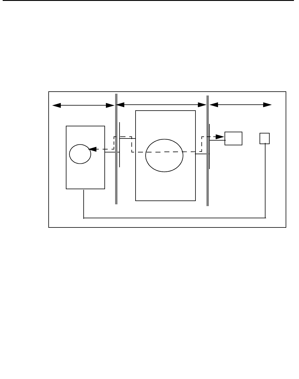
Although a CTI implementation can take many forms, Figure 1-1 depicts a simple model of
CTI in terms of Avaya Computer Telephony components. This model depicts a DEFINITY
switch that relies on the Adjunct Switch Application Interface (ASAI) to effect
communications with adjuncts (such as the Avaya Computer Telephony server).
Figure 1-1: Essential Components of Avaya Computer Telephony — A High Level
View
DEFINITY
ECS
Avaya CT Server TSAPI
Client
Telephony
Software
Services Agent
Workstation
Agent
Telephone
Phone Line
Switch Server Client
ASAI

A Typical Avaya Computer Telephony Configuration
Issue 1 October 2003 27
A Typical Avaya Computer Telephony Configuration
This section provides a high-level description of the hardware and software components
used in a typical Avaya Computer Telephony configuration.
Hardware Components in a Typical Implementation of Avaya
Computer Telephony
The basic hardware components in a typical Avaya Computer Telephony configuration are
as follows.
●DEFINITY Switch configured with ASAI
The DEFINITY switch is a device that processes calls (incoming, outgoing, and
internal) and connects them to the proper destinations.
In the context of Avaya Computer Telephony, the role of the DEFINITY switch
changes. In a Avaya Computer Telephony implementation, the DEFINITY switch
“hands off” call monitoring and call control functions to the Avaya Computer Telephony
server (or the adjunct processor). The means of effecting this handoff is the Adjunct
Switch Application Interface — ASAI.
To support Avaya Computer Telephony, the DEFINITY switch must be configured with
Adjunct Links or an ASAI Interface. DEFINITY switches that support CTI are as
follows.
- DEFINITY CSI, Si, and R (running software release G3V4 or later), Avaya
MultiVantage on a DEFINITY Server CSI, SI, and R, and Avaya MultiVantage S8700
configurations
Note:
Note: G3V4 requires a field maintenance release.
- DEFINITY ONE/IP600 Release 2 (R2), or later, and Avaya MultiVantage S8100
configurations
●DEFINITY LAN Gateway
The DEFINITY LAN Gateway, or DLG, is software that acts as a transport mechanism
that allows the DEFINITY switch to communicate with the Avaya Computer Telephony
server. It is required for all Avaya Computer Telephony implementations.
- DEFINITY CSI, Si, and R (running software release G3V4 or later), Avaya
MultiVantage on a DEFINITY Server CSI, SI, and R, and Avaya MultiVantage S8700
configurations use a Multi-Application Platform for DEFINTY (MAPD) based DLG.

Learning About Avaya Computer Telephony
28 Installation Guide
- DEFINITY ONE/IP600 and Avaya MultiVantage S8100 configurations use the Co-
Resident DLG (without a MAPD board).
●Avaya Computer Telephony Server
The adjunct processor that performs call monitoring and control functions, security
database functions, and link management. Avaya Computer Telephony runs on
Windows NT, Windows 2000, or Windows XP.
●Avaya Computer Telephony Client Workstations
Client workstations run the applications that interact with the Avaya Computer
Telephony server.

Avaya Computer Telephony Components
Issue 1 October 2003 29
Avaya Computer Telephony Components
The Avaya Computer Telephony CD ROM contains the following software components:
●Security Database for Telephony Services (Used by Telephony Services for client
authentication; it is not used by CVLAN.)
●Telephony Services Server (Tserver) Software
●Telephony Services Client Software
- Windows NT, Windows 2000, or Windows XP
- UnixWare
- Solaris Sparc
- HP-UX
●CVLAN Server
●CVLAN Clients
- UNIX
- Solaris x86
- Solaris Sparc
- Windows NT, Windows 2000 or Windows XP
- IBM Advanced Interactive Executive (AIX)
●DEFINITY Driver (G3 PBX Driver)
●TSAPI Software Development Kit (SDK)
●JTAPI SDK
●CVLAN SDK
●Online Avaya Computer Telephony documents and Adobe Acrobat Reader
Learning About Avaya Computer Telephony
30 Installation Guide
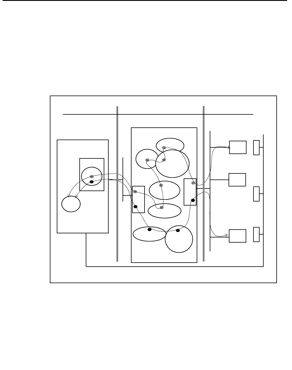
A Closer Look at the Essential Avaya Computer
Telephony Components
The view of Avaya Computer Telephony depicted by Figure 1-2 includes the some of the
major components described in ‘‘A Typical Avaya Computer Telephony Configuration’’ on
page 27, to give you a better sense of where the components are and how they operate at
a schematic level.
Figure 1-2: Essential Avaya Computer Telephony Components — A Closer Look
ASAI.DLL
TSLIB
SDB
DEFINITY ECS
Avaya CT Server
TSAPI
Client
Tserver
Phone
Phone Line
NIC
NIC
G3PD
CVLANCLI.DLL
DLG
MAPD
JTAPI
Client
CVLAN
Client
ASAI
CVLAN
Server
Phone Phone
Switch Server Client

Security Issues
Issue 1 October 2003 31
Security Issues
The term security has broad connotations. In the context of Avaya Computer Telephony,
security refers to toll fraud issues only. The next two sections provide some basic
guidelines for effecting secure, isolated LAN arrangements for DEFINITY. For more
information about security-related issues, see Chapter 2 of Avaya Computer Telephony 1.3
G3 PBX Driver and CVLAN Administration and Maintenance (DEFNETM.PDF).
Security — DEFINITY Servers CSI, SI, R
and S8700 Configurations
If your Avaya Computer Telephony configuration relies on a platform that uses the MAPD
(DEFINITY Server CSI, SI, R and S8700 Configurations) refer to Figure 1-3 as you read
this section.
Isolating the DEFINITY LAN Gateway
The DEFINITY LAN Gateway system assembly should be on its own separate segment
and will consequently require its own separate LAN card. This means you will need two
network interface cards (NICs) in your Telephony Server, one for client access and one for
the connection between the DEFINITY G3 PBX Driver and the DEFINITY LAN Gateway
system assembly.
Follow these guidelines to ensure that the DEFINITY LAN Gateway system is not
accessible from the rest of the network.
●Use a separate secure link connecting the Telephony Server to the DEFINITY LAN
Gateway system.
●You will administer the IP address of the DEFINITY G3 PBX Driver during the
installation of the DEFINITY G3 PBX Driver. Do not administer the same IP address for
the DEFINITY G3 PBX Driver that your Telephony Server is using. If you do administer
the same IP address for both, you will leave your system open for possible toll fraud and
may receive a toll fraud warning.
●Make sure that IP forwarding (formerly referred to as IP routing) is turned off between
the DEFINITY G3 PBX Driver NIC and the NIC on the Avaya Computer Telephony
Server. After installing the NIC on your Avaya Computer Telephony server, configure the
connection with no IP forwarding. See “Configuring the Tserver for a Secure LAN
Gateway Connection” in Chapter 2 of Avaya Computer Telephony 1.3 G3 PBX Driver
and CVLAN Administration and Maintenance (DEFNETM.PDF).
Learning About Avaya Computer Telephony
32 Installation Guide
!WARNING:
WARNING: Customers who do not follow this recommendation may be subject to a
person or persons gaining illegal access to the DEFINITY LAN Gateway
application to commit toll fraud and/or tamper with the real-time aspects of
Computer Telephony Integration (CTI) applications. (Toll fraud is the
unauthorized use of your telecommunications system. Under applicable law,
the customer is responsible for paying for such unauthorized usage.)
Figure 1-3: DEFINITY ECS/DEFINITY Server CSI Security Guidelines
G3PBX
Telephony
Server
(TSRV)
Client access
Separate LAN segment
Separate LAN segment
Driver
Ethernet
DEFINITY ECS Avaya CT
Clients
rest of the network.
connections isolated from the
Prohibit any routing between
the NIC used for the DEFINITY LAN
Gateway and any other NIC.
Switch access
Keep the DEFINITY LAN Gateway
Server
DEFINITY
LAN
Gateway
192.168.25.10
192.168.25.20
NIC
NIC
176.108.25.20
Security Issues
Issue 1 October 2003 33
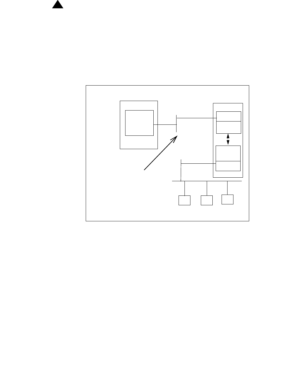
Security — DEFINITY ONE/IP600and Avaya MultiVantage
S8100 Configurations
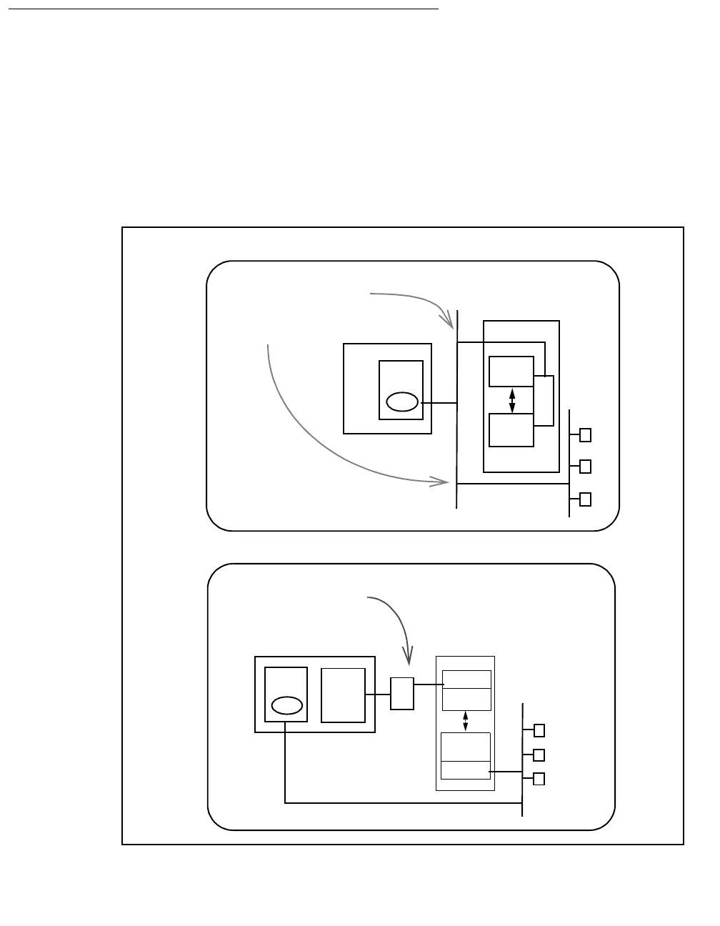
Figure 1-4 depicts two optional connection methods, a non-isolated link on the same LAN
segment and an isolated, secure link on a separate LAN segment. Be sure to review
Figure 1-4 and note the security issues and toll fraud implications. Use a separate, secure
link connecting to DEFINITY ONE/IP600 or S8100 Media Server configuration.
Figure 1-4: Connectivity Options
Telephony
Server
(TSRV)
Client access
DEFINITY ONE
Avaya CT
Switch access
Server
TN2314
PROCR
DLG
With this connection option,
DEFINITY ONE is not
isolated from the
rest of the network.
The client and the switch use
the same LAN segment.
Connectivity via TN2314 PROCR — Non-Isolated or Same LAN segment
Clients
G3PBX
Driver
NIC
G3PBX
Telephony
Server
(TSRV)
Client access
Driver
DEFINITY ONE
Avaya CT
Clients
Switch access
Server
NIC
NIC
With this connection option,
the DEFINITY ONE-to-server
connection is isolated from
the rest of the network.
TN2314
PROCR
DLG
TN799
C-LAN
Clients are not on the same
LAN segment as the switch.
Connectivity via TN799 CLAN — Isolated or Separate LAN segment
HUB

Learning About Avaya Computer Telephony
34 Installation Guide
Implementing a Firewall Strategy
Avaya Computer Telephony supports a variety of configuration methods and addressing
techniques that are used in a firewall environment. The documentation presents the
information in terms of where you are setting up your firewall.
●If you are setting up a firewall between the Avaya Computer Telephony client and the
Avaya Computer Telephony Server (Tserver), see Chapter 6 of the Telephony Services
Administration and Maintenance Guide (NETMANGD.PDF).
●If you are setting up a firewall between the G3PBX driver (located on the Avaya
Computer Telephony Server) and the switch, see Chapter 2 of the G3PBX Driver and
CVLAN Administration and Maintenance Guide (DEFNETM.PDF).
Note:
Note: While Avaya Computer Telephony can support a firewall on either side of the
Tserver, it is recommended that the firewall be placed between the Tserver
and the client rather than the Tserver and the switch.

Private Data and Client Applications
Issue 1 October 2003 35
Private Data and Client Applications
Private Data allows Avaya Computer Telephony to take advantage of DEFINITY features.
A complete description of private data is beyond the scope of this document, but a simple
overview will help you understand how if affects your applications. At a conceptual level the
main points are as follows.
●Private data is a switch-specific software implementation that provides value added
services. Your applications can take advantage of the private data services that are
included in the Telephony Services API.
●An application that is based on “Private Data Version 5,” for example, can run on a
switch that is running “Private Data Version 6,” but the application is restricted to the
capabilities of Private Data Version 5. In this sense, private data version control is
transparent, or backward compatible.
●If you want your Private Data Version 5 based applications to take advantage of Private
Data Version 6 capabilities, you must upgrade all the services your application uses to
Private Data Version 6.
For more information about private data services, see Avaya Computer Telephony,
Telephony Services Application Programming Interface (TSAPI) for Avaya MultiVantage
(DEFPROG.PDF). Table 1-1 summarizes application client platforms and private data
version compatibility.
Table 1-1: Avaya Computer Telephony Client Platforms - Private Data Version
Compatibility
Win32® Windows 95 All versions
Windows 98
Windows NT 3.5.1 workstation or server
Windows NT 4.0 workstation or server
Windows 2000 Professional or Server
Windows XP
Solaris Sparc Solaris Sparc All versions
UnixWare UnixWare 1.x, UnixWare 2.0x, UnixWare 7 All versions
HP-UX HP-UX Version 10 V5 and earlier
Java (JTAPI) Java VM1
1. Any Java Virtual Machine (VM) compatible with the Sun Microsystems Java specification, Version
1.02 or later.
All versions
Netscape Navigator® 3.x + or Internet Explorer™
4.x +

Learning About Avaya Computer Telephony
36 Installation Guide

Issue 1 October 2003 37
Chapter 2: Administering the Switch
This chapter describes DEFINITY-based tasks that must be performed to implement
communications between the DEFINITY switch and the Avaya Computer Telephony
server.
This chapter contains the following sections:
●Scope of this Chapter on page 37
●Hardware and Software Components on page 38
●Using the Information in this Chapter on page 39
●Activating Software Features — RFA and License Files on page 40
●License Files on page 40
●License File and Optional Features Forms on page 40
●Administrative Tasks for Avaya Platforms That Use the MAPD on page 41
●Administrative Tasks for Avaya Platforms That Use the Co-Resident DLG on page 53
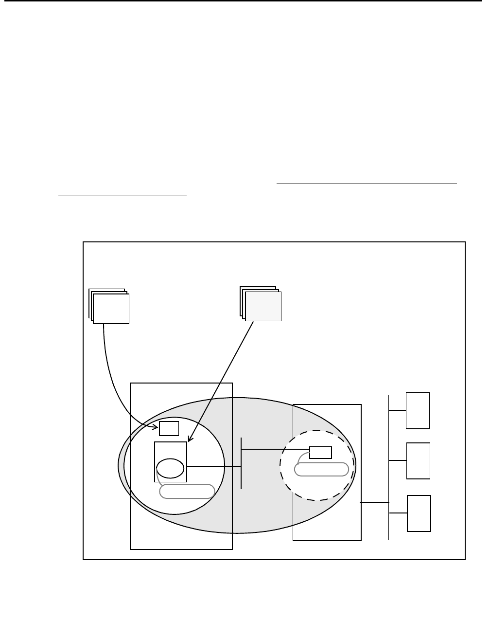
Scope of this Chapter
Refer to Figure 2-1 as you read this section. The scope of this chapter includes activities
associated with setting up the DEFINITY switch, administering the communications
interface to the Avaya Computer Telephony server, and establishing a link. The next
sections describes the components that are affected.

Administering the Switch
38 Installation Guide
Hardware and Software Components
The hardware and software components relevant in this chapter are described in this list.
●Avaya MultiVantageTM software — the call processing software that resides on all
Avaya call processing configurations. From the viewpoint of product names, it is part of
the name of each call processing platform.
●The DEFINITY Server, the Media Server, or the Media Gateway (such as DEFINITY
Server CSI, DEFINITY Server SI, and DEFINITY Server R, Avaya S8100 Media Server
configurations, Avaya S8300 with Avaya Media Gateway, and Avaya MultiVantage
S8700 Media Server configurations)
●DEFINITY LAN Gateway (DLG), software which can reside on the Multi-Application
Platform for DEFINITY (MAPD) or can be Co-Resident with call MultiVantage Processor
Card. The following list describes the platforms that rely on the MAPD DLG and the
platforms that rely on the Co-Resident DLG.
●Platforms that use the TN800 series MAPD
●DEFINITY Servers (CSI, SI, and R), and Avaya MultiVantage S8700 Media Server
configurations.
●Platforms that use the Co-Resident DLG (the DLG software co-resides with
MultiVantage call processing on the processor card.
- Avaya S8100 Media Server configurations (formerly DEFINITY ONE and IP 600)
- Avaya S8300 Media Gateway with G700 Media Server (with an Internal Call
Controller)
Note:
Note: In some configurations, the TN2314 card (with Co-Resident DLG) relies on
the TN799 Control LAN (C-LAN) card for LAN isolation.

Using the Information in this Chapter
Issue 1 October 2003 39
Using the Information in this Chapter
This chapter makes two basic assumptions — that you have a DEFINITY switch, with the
DEFINITY LAN Gateway (DLG) system already installed, and that you have a TCP/IP
based LAN that is capable of isolating your server-based functions from your client-based
functions.
The type of DEFINITY switch you have determines how you use this chapter.
●If you use a DEFINITY Server (CSI, SI or R) or an Avaya MultiVantage S8700 Media
Server configuration, complete the tasks described in ‘‘Administrative Tasks for Avaya
Platforms That Use the MAPD’’ on page -41.
●If you use an Avaya MultiVantage S8100 Server (formerly DEFINITY ONE/IP600) or an
Avaya MultiVantage S8300 Media Server with a G700 Media Gateway, complete the
tasks described in ‘‘CTI Link Administration on Configurations with Processor
Connectivity’’ on page -54
●If you use an Avaya S8100 Media Server (DEFINITY ONE/IP600) configuration with a
processor and C-LAN, see ‘‘CTI Link Administration on Configurations with CLAN
Connectivity’’ on page -56

Administering the Switch
40 Installation Guide
Activating Software Features — RFA and License
Files
With Release 10, Avaya implemented a new approach to activating software features. This
new approach relies on the Remote Feature Activation (RFA) process and the creation of a
License file. All activities associated with RFA and the generation of license files are
carried out by Avaya support. To change software features, you will need to contact your
Account Executive and have a new license file generated via the RFA process.
License Files
All DEFINITY R10, and subsequent MultiVantage systems require a valid license to
operate as a switch.The License File controls following switch settings:
●software release
●offer category
●features
●capacities
Without a license file, the switch does not provide normal call processing.
License File and Optional Features Forms
Because the license file determines features and capabilities, the ASAI Optional features
that appear on the OPTIONAL FEATURES form are pre-set, or inherited from the license
file, and switch administrators cannot change them.
For example, if you type display system parameters and go to the page that lists
optional features for ASAI (typically page 2) you would see the settings that were effected
by the license file.
If your form lists ASAI Link Plus Capabilities? n, it means that your system has
not been set up with ASAI Link Plus Capabilities. You can not change the "n" to a "y" on
this form. To do so you would have to contact your AE and make arrangements to have the
change implemented through RFA.
Administrative Tasks for Avaya Platforms That Use the MAPD
Issue 1 October 2003 41
Administrative Tasks for Avaya Platforms That Use
the MAPD
This section describes administrative tasks you must complete before you can install
Avaya Computer Telephony in a configuration that uses a MAPD, such as DEFINTY
Servers (CSI, SI, and R), Avaya MultiVantage S8700 Media Server for Multi-Connect
Configurations, and Avaya MultiVantage S8700 Media Server for IP-Connect
Configurations.
●Task 1: Administration on a DEFINITY System Administration Terminal (SAT)
●Task 2: MAPD and DLG Administration via a MAPD Administration Terminal
Once you complete these tasks, proceed with Chapter 3: Installing Avaya Computer
Telephony Server Software.
Figure 2-1: DEFINTY Server and MAPD/DLG Administration at a Glance
DEFINITY ECS Avaya CT Server Clients
DEFINITY ECS and DEFINITY
Server CSI Administration DLG Administration
via MAPD Administration terminal
Verify software version
Verify ASAI features
List configuration
Administer station
Add a client — TCP/IP ADMINISTRATION
Administer a link — PORT ADMINISTRATION
DLG ADMINISTRATION
Verify connectivity — DLG PORT/STATUS
LOCAL HOST TABLE
(MAPD in “ASAI” state)
Task 2
via SAT terminal
Task
1
CONTROL
NIC
MAPD
DLG 192.168.25.20
192.168.25.10

Administering the Switch
42 Installation Guide
Setting Up Your LAN for Avaya Computer Telephony
This section applies to the following platforms, which rely on the MAPD-based DLG and
rely on a Telephony Server with two Network Interface Cards (NICs). If you are configuring
Avaya Computer Telephony in a NAT or a firewall environment, see Implementing a
Firewall Strategy on page 34.
●DEFINITY Servers CSI, SI, and R
●Avaya MultiVantage S8700 Media Server for Multi-Connect Configurations
●Avaya MultiVantage S8700 Media Server for IP-Connect Configurations
Before you administer the DEFINITY switch (including the DLG), make sure that you have
determined how your LAN is set up.
Server LAN Segment (connectivity to the switch)
Server LAN segment functions are in the DLG administrative domain. For server-to-switch
functions follow these guidelines.
●The DLG must be connected to the LAN that the Avaya Computer Telephony server
uses (the Avaya Computer Telephony server communicates with the switch via the
DEFINITY G3 PBX Driver).
●The DLG should be on its own separate LAN segment. To effect this, you will need two
Network Interface Cards (NICs) in the Avaya Computer Telephony Server, one for client
access and one for the connection between the DLG and the DEFINITY G3 PBX Driver.
IP Addresses
It is strongly recommended that you use at least two IP addresses.
●IP address for the DLG
Make certain that you have the IP address or the DLG or its host name (if host
names are used instead of IP addresses). See the DEFINITY switch administrator.
If you are using a separate LAN for your DLG (recommended) and all links go to a
single switch, then you can use the default IP address, which is 192.168.25.10.
●IP Address for the DEFINITY G3 PBX Driver
Verify that you have a local IP address for the DEFINITY G3 PBX Driver on your
Telephony Server. You will need this IP address for installing the DEFINITY G3 PBX
Driver. You may obtain this address from the network administrator or you may use
the default address provided in the installation program (192.168.25.20) if you have
a private LAN (as recommended) between the Telephony Server and the DEFINITY
ECS switch. This local IP address should be different from the IP address used for
the Avaya Computer Telephony server, as recommended.

Administrative Tasks for Avaya Platforms That Use the MAPD
Issue 1 October 2003 43
Client LAN Segment
See Chapter 4: Installing Avaya Computer Telephony TSAPI Client Software for more
information about client-based Avaya Computer Telephony requirements.
Guidelines for Setting Up a Private LAN
Follow these guidelines for implementing a private LAN for Avaya Computer Telephony.
Use IP addresses within the following ranges:
●10.0.0.0 — 10.255.255.255
●172.16.0.0 — 172.31.255.255
●192.168.0.0 — 192.168.255.255
If You Intend to Use Host Names
You have the option of using host names, instead of IP addresses, when administering the
DEFINITY LAN Gateway and the DEFINITY G3 PBX Driver. If you use host names instead
of IP addresses, each entry in the HOSTS file provides information about one host on the
IP network. The DEFINITY LAN Gateway link connection is considered a host.
Note:
Note: The DLG has a default set of administered parameters that correspond to
the defaults provided in the Avaya Computer Telephony DEFINITY G3 PBX
Driver installation. If you implement private addressing you will have to
change these settings on the G3PBX Driver Configuration Dialog Box (see
Chapter 3: Installing Avaya Computer Telephony Server Software .)
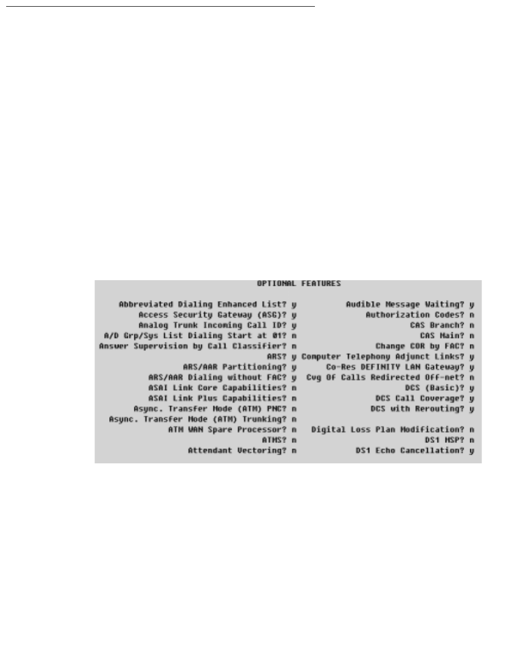
Administering the Switch
44 Installation Guide
Task 1: Administering a Link
This section applies to the following platforms, which rely on the MAPD-based DLG.
●DEFINITY Servers CSI, SI, and R
●Avaya MultiVantage S8700 Media Server for Multi-Connect Configurations
●Avaya MultiVantage S8700 Media Server for IP-Connect Configurations
The objective of Task 1 is administering a link. From the DEFINITY SAT, follow these steps
to complete Task 1.
Note:
Note: Whenever you use the change form of a DEFINITY SAT command, you
must log out for the changes to take effect.
1. Log in to the DEFINITY switch.
2. Type display system-parameters customer-options
The OPTIONAL FEATURES screen appears.
3. Check Computer Telephony Adjunct Links? and make sure it is set to y, (page
2 of the OPTIONAL FEATURES screen in the example above). This setting indicates
that DEFINITY is capable of communicating with an adjunct.
Note:
Note: If this field is not set to "y" then contact your Avaya Account Representative.
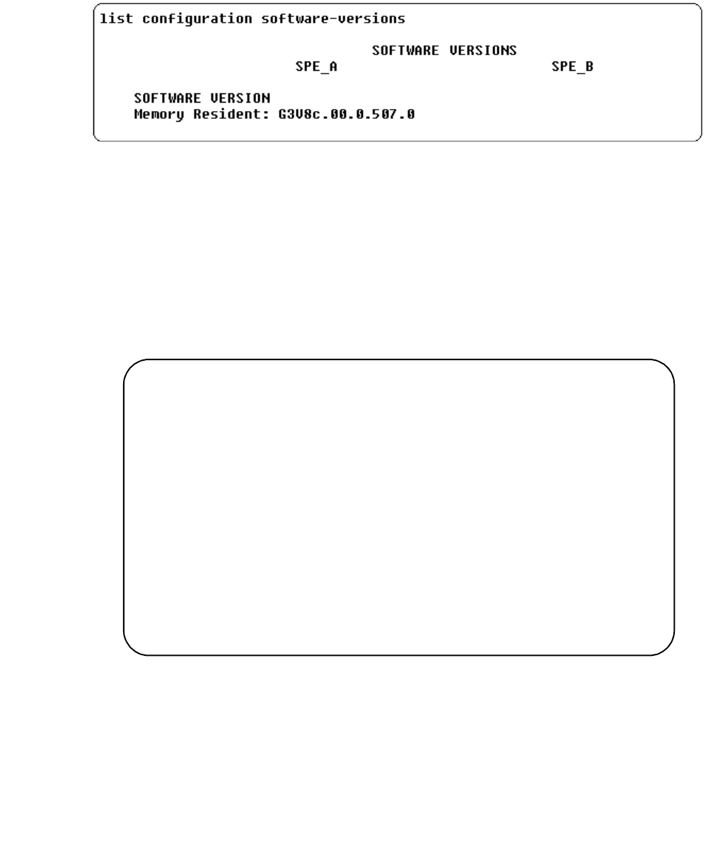
Administrative Tasks for Avaya Platforms That Use the MAPD
Issue 1 October 2003 45
4. Type list configuration software-versions
The SOFTWARE VERSIONS screen appears.
5. Check the SOFTWARE VERSION to verify that the correct DEFINITY software version
is running on the switch. The following versions are appropriate: G3V4, or later.
Note:
Note: G3V4 requires a field maintenance release.
6. Type list config all to determine what ports are available on the MAPD for
adding a station.
The SYSTEM CONFIGURATION screen appears.
Under Assigned Ports, each u represents an available or unassigned port.
7. Choose a port associated with the MAPD board to add a station to the DLG (on the
MAPD).
8. Type add cti-link <n> (where n represents the link number)
The LINK screen appears.
list configuration all
Page 1
----------------------------------------------------------------------
SYSTEM CONFIGURATION
Board
Number
1A01
1A02
1A03
1A04
1A05
1A06
Board Type Code Vintage Assigned Ports
EXPANSION INTF
EXPANSION INTF
RESERVED LGATE
RESERVED LGATE
MAPD BOARD
TN776
TN776
TN801
TN801
TN801
000001
000001
MAPD
MAPD
000001
u u u u u u u u
u u u u u u u u
01 u u u u u u u
u u u u u u u u
u u u u u u u u
u u u u u u u u

Administering the Switch
46 Installation Guide
9. Follow Steps a through i to add an ASAI-enabled station. Completing the LINK screen
administers an adjunct IP link between DEFINITY and a Avaya Computer Telephony
server.
a. In the Extension: type any valid extension on the dial plan (for example, 1008).
b. In the Type: field, type ADJLK
c. In the Port: field, type an available port number
d. In the Name: field, type the name of the Avaya Computer Telephony server
e. In the XID: field, accept the default (n)
f. In the Fixed TEI: field, type y
g. In the MIM Support: field, accept the default (n)
h. In the CRV Length: field, type 2
i. In the Event Minimization: field, accept the default (n)
All other fields on the Link screen use the default values.
This completes Task 1: DEFINITY Administration. Proceed to Task 2: DLG Administration.
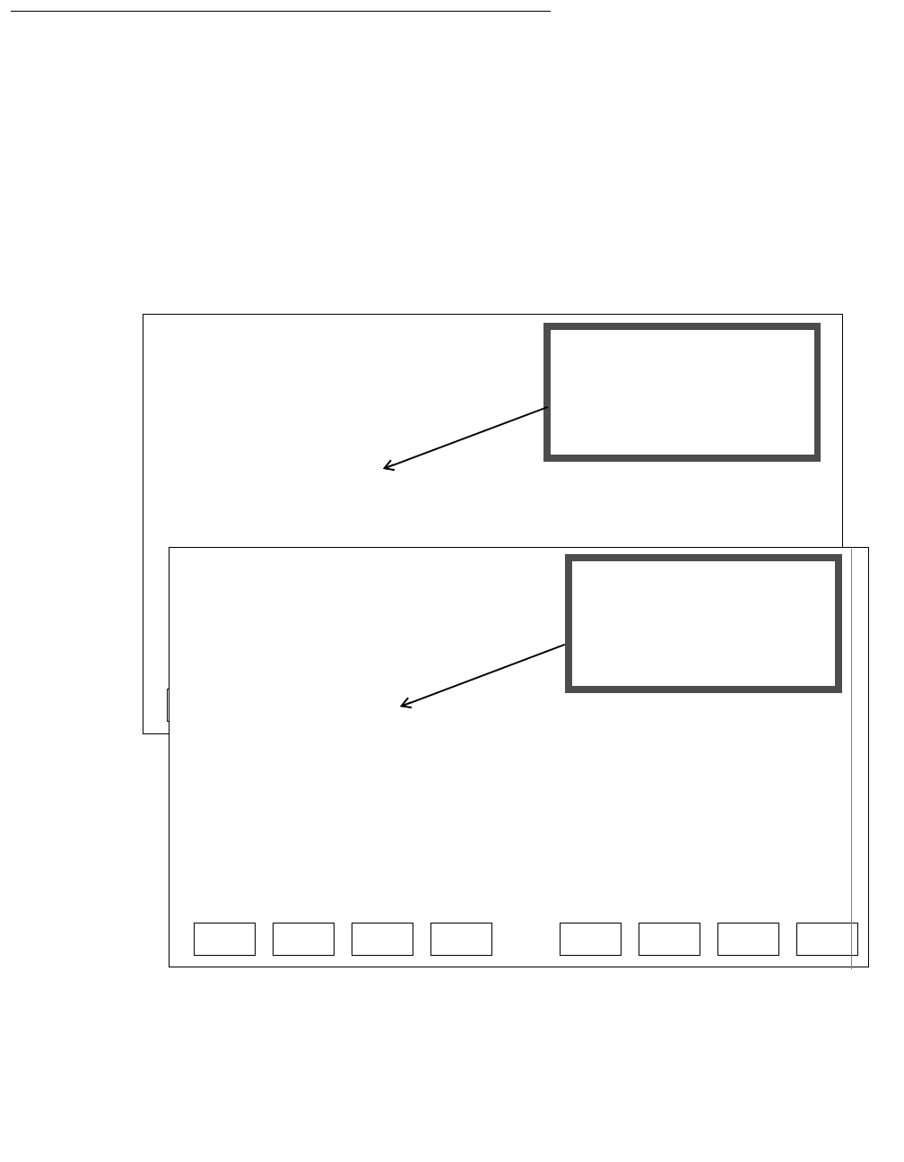
Administrative Tasks for Avaya Platforms That Use the MAPD
Issue 1 October 2003 47
Task 2: DLG Administration
The objective of Task 2 is to establish connectivity between DEFINITY and your Avaya
Computer Telephony server, by way of the DLG. Task 2 assumes that the DLG is already
installed and administered. For more information see DEFINITY ECS and CallVisor ASAI
Applications over MAPD (555-230-136).
From the MAPD administrative terminal, follow these steps to complete Task 2.
1. Log in to the MAPD system
The Main Menu appears.
2. From the Main Menu, select 2. TCP/IP Administration.
Main Menu
This line is used to provide abbreviated help on the currently selected field.
ENTEREXIT REFRESH HELP
1. Login/Password Administration
2. TCP/IP Administration...
3. Port Administration...
4. Maintenance...
5. DLG Port Status/Control
6. CV/LAN Port Status/Control
7. Exit Main Menu
This line is used to provide abbreviated help on the currently selected field.
ENTEREXIT REFRESH HELP
1. Login/Password Administration
2. TCP/IP Administration...
3. DLG Administration
4. Maintenance...
5. DLG Port Status/Control
6. Exit
If both the DLG and CVLAN
applications are on the MAPD
this Main Menu appears.
If only the DLG application
is on the MAPD
this Main Menu appears.
3. Port Administration... is
for access to DLG and CVLAN)
3. DLG Administration
for access to DLG.
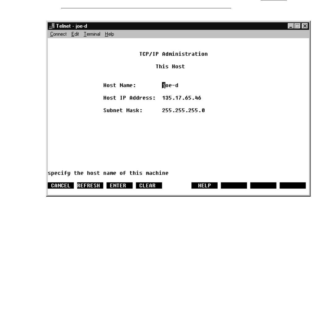
Administering the Switch
48 Installation Guide
3. From the TCP/IP Administration screen select 1. This Host
The TCP/IP Administration This Host screen appears (This Host refers to the MAPD
itself).
4. Verify (or make a note of) the Host Name and IP address of the MAPD.
●The Host Name is the name that you assign to the MAPD.
●The Host IP Address is the IP address required when you perform G3 PBX Driver
link administration on the Avaya Computer Telephony Server. See Chapter
3: Installing Avaya Computer Telephony Server Software.
5. Once you have noted this information, select CANCEL to return to the Main Menu.
Administrative Tasks for Avaya Platforms That Use the MAPD
Issue 1 October 2003 49
6. From the Main Menu, select 2. TCP/IP Administration.
The TCP/IP Administration screen appears.
7. From the TCP/IP Administration screen select 2. Local Host Table, which
enables you to view, add, or delete hosts. The host, in this case, is the Avaya
Computer Telephony Server.
The TCP/IP Administration Local Host Table screen appears.
1. This Host
2. Local Host Table
3. Network Routing Information...
4. Exit
TCP/IP Administration
This line is used to provide abbreviated help on the currently selected field.
ENTEREXIT REFRESH HELP

Administering the Switch
50 Installation Guide
Note:
Note: If the MAPD/DLG has already been administered to accept the default IP
address of the Avaya Computer Telephony server (192.168.25.20), and you
want to implement a default Avaya Computer Telephony configuration, skip
Step 8a and 8b; go to Step 8c.
8. Follow Steps a through e to complete the Local Host Table
Note:
Note: The addressing information you use in steps 8a and 8b must be used (in the
DEFINITY G3PBX Driver dialog box) when you install Avaya Computer
Telephony.
a. In the IP Address field, type the IP address of the G3PBX Driver on the Avaya
Computer Telephony server. (You can accept the default, 192.168.25.20, if you want
to effect a "default" Avaya Computer Telephony installation).
b. In the Host Name field, type the name that is assigned to the Avaya Computer
Telephony server.
c. Select ADD to save your settings.
d. Select CANCEL to return to the TCP/IP Administration Screen.
e. From the TCP/IP Administration Screen, select EXIT to return to the MAIN MENU.
TCP/IP Administration
___________________________________________________________________________
ADD DELETECANCEL REFRESH NXTPG PRVPGHELP
This line is used to provide abbreviated help on the currently selected field.
___________________________________________________________________________
___________________________________________________________________________
___________________________________________________________________________
___________________________________________________________________________
___________________________________________________________________________
___________________________________________________________________________
___________________________________________________________________________
Local Host Table
___________________________________________________________________________
___________________________________________________________________________
__________________________________________________________________
___________________________________________________________________________
___________________________________________________________________________
___________________________________________________________________________
___________________________________________________________________________
IP Address
X of X
Page
Host Name Aliases
Administrative Tasks for Avaya Platforms That Use the MAPD
Issue 1 October 2003 51
9. From the Main Menu, select 3. Port Administration...
The Port Administration screen appears.
10. From the Port Administration screen, select 2. DLG Administration
The DLG Administration screen appears.
11. Follow steps a through c to complete the DLG Administration screen.
1. Application Port Assignment
2. DLG Administration
3. CV/LAN Administration
4. Exit
Port Administration
This line is used to provide abbreviated help on the currently selected field.
ENTEREXIT REFRESH HELP
DLG Administration
Client Name or IP Address
_________________________
Port
__
Client Link
__
ADD DELETECANCEL REFRESH UPDATEHELP
Client Status
___________
___________________________ __ ___________
___________________________ __ ___________
___________________________ __ ___________
___________________________ __ ___________
___________________________ __ ___________
___________________________ __ ___________
___________________________ __ ___________
This line is used to provide abbreviated help on the currently selected field.
Administering the Switch
52 Installation Guide
a. In the Port field, type the port number of the DEFINITY station administered for the
link to the Avaya Computer Telephony server (see Task 1, Step 8a)
b. In the Client Name or IP Address field, type the IP address or name assigned
to the G3PBX Driver on the Avaya Computer Telephony server. This Client Name or
IP Address refers to the IP address you used in Step 8b.
(The default is 192.168.25.20).
c. In the Client Link field, type a number from 1 to 8 for the link assigned to the
Avaya Computer Telephony server.
12. Return to the Main Menu, and from the Main Menu, select
5. DLG Port/Status Control.
The DLG Port/Status Control screen appears.
13. From the DLG Port Status/Control screen follow these steps.
a. Verify that the port number you administered in Step 11a appears under Port.
b. Verify that REACHABLE appears under TCP/IP Connection State.
This completes the DLG/MAPD administrative tasks.
DEFINITY
Port
__________________________________________________________________
TCP/IP
MSGPERCANCEL REFRESH UPDATE DROPHELP STATE
This line is used to provide abbreviated help on the currently selected field.
Port
State Connection
State
DLG
Service
State
Messages
to
DEFINITY
Messages
from
DEFINITY
Message
Period
(minutes)
__________________________________________________________________
__________________________________________________________________
__________________________________________________________________
__________________________________________________________________
__________________________________________________________________
__________________________________________________________________
__________________________________________________________________

Administrative Tasks for Avaya Platforms That Use the Co-Resident DLG
Issue 1 October 2003 53
Administrative Tasks for Avaya Platforms That Use
the Co-Resident DLG
This section applies to the following platforms, which can use the Co-Resident DEFINTY
LAN Gateway (DLG).
●DEFINITY ONE/IP 600
●Avaya MultiVantage S8100 Media Server configurations
●Avaya MultiVantage S8300 Media Server with G700 Media Gateway
Because these platforms do not use the MAPD based DLG, there is no MAPD
Administration. Based on your configuration, use one of the following procedures to
administer a CTI link
●CTI Link Administration on Configurations with Processor Connectivity on page 54
●CTI Link Administration on Configurations with CLAN Connectivity on page 56 (NOTE:
This procedure is not applicable to the S8300 Media Server configuration).

Administering the Switch
54 Installation Guide
CTI Link Administration on Configurations with Processor
Connectivity
This procedure assumes that you are running the appropriate level of software. Follow
these steps from the system access terminal (SAT) to administer a CTI link (Link Type:
ADJ-IP) in a configuration that supports a Co-Resident DLG, such as DEFINITY ONE/
IP600, Avaya S8100 Media Server configurations, or an Avaya S8300 Media Server with
G700 Media Gateway.
Note:
Note: Italicized terms in angle brackets denote variables, for example
<123.213.123.111>. Substitute the appropriate value for your system.
1. Type list configuration software-versions and verify that the appropriate level of
software is running (R11.00.059 or later)
2. Type display system-parameters customer-options, and go to Page 4 of 101 of the
OPTIONAL FEATURES form.
Verify that the Processor Ethernet? option field, is set to y.
3. Type display system-parameters customer-options and go to Page 2 of 10 of the
OPTIONAL FEATURES form.
Verify that the Co-Res DEFINITY LAN Gateway? option field, is set to y.
4. Type display system-parameters customer-options and go to page 2 of 10 of the
OPTIONAL FEATURES form.
Verify that Computer Telephony Adjunct Link is set to y.
5. Type change ip-interfaces and go to Page 1 of 6 of the IP INTERFACES form. Follow
Steps a thorough f.
a. In the Enable Eth Pt option field, type y
b. In the Type option field, type procr
c. In the Net Rgn option field, type 1 or the appropriate Network region
d. In the Node Name option field, type the Processor’s IP address; for example:
<123.213.123.111>
e. In the Subnet Mask option field, type the Processor’s subnet mask, for example:
<255.255.255.0>
f. In the Gateway option field, type the router’s IP address, for example
<123.213.321.110>
6. Type change node-names. (You are on Page 1 of 1 on the IP NODE NAMES form.)
a. In the Name option field, type <the TServer’s Hostname>
1 Page numbering is relative on the OPTIONS form. The total page count is affected by the options your
system is configured with. For example, if you have ASAI Core but neither ASAI Plus nor Computer
Telephony Adjunct Links, your total page count diminishes by one (4 of 9 instead of 4 of 10).

Administrative Tasks for Avaya Platforms That Use the Co-Resident DLG
Issue 1 October 2003 55
b. In the IP Address option field, type <the TServer’s IP Address>
7. type add cti link <n> (substitute with the appropriate link number)
a. In the Extension field, type <station extension>
b. In the Type field, type ADJ-IP
c. In the Name field, type <name of the TServer>
8. type change ip-services
a. In the Service Type field, type DLG
b. In the Enabled field, type y
c. In the Local Node field, type procr
d. In the Local Port field, type 5678
9. After completing the IP-Services Form (Step 9), continue on to the DLG Administration
form.
a. In the CTI Link field, type <n> (substitute with the appropriate link number)
b. In the Enabled field, type y
c. In the Client Name field, type <TServer’s node name>
d. In the Client Link field, type <TServer’s Link Number>
10. Type status dlg cti-link, and on the DLG CTI LINK STATUS form, verify that the
Service State field displays established.

Administering the Switch
56 Installation Guide
CTI Link Administration on Configurations with CLAN
Connectivity
This procedure assumes that you are running the appropriate level of software. Follow
these steps from the system access terminal (SAT) to administer a CTI link (Link Type:
ADJ-IP) in a configuration that supports a Co-Resident DLG.
Note:
Note: This procedure applies only to DEFINITY ONE/IP600 and Avaya S8100
Media Server configurations. It does not apply to S8300 Media Server
configurations.
1. Type list configuration software-versions and verify that the appropriate level of
software is running (R11.00.059 or later)
2. Type display system-parameters customer-options, and go to Page 4 of 101 of the
OPTIONAL FEATURES form.
Verify that the Processor Ethernet? option field, is set to y.
3. Type display system-parameters customer-options and go to Page 2 of 10 of the
OPTIONAL FEATURES form.
Verify that the Co-Res DEFINITY LAN Gateway? option field, is set to y.
4. Type display system-parameters customer-options and go to page 2 of 10 of the
OPTIONAL FEATURES form.
Verify that Computer Telephony Adjunct Link is set to y.
5. Type change ip-interfaces and go to Page 1 of 6 of the IP INTERFACES form. Follow
Steps a thorough f.
a. In the Enable Eth Pt option field, type y
b. In the Type option field, type c-lan
c. In the Net Rgn option field, type 1 or the appropriate Network region
d. In the Node Name option field, type the <C-LAN’s Node Name>
e. In the Subnet Mask option field, type the <C-LAN’s Subnet Mask>
f. In the Gateway option field, type the <Router’s IP address>
6. Type change node-names. (You are on Page 1 of 1 on the IP NODE NAMES form.)
a. In the Name option field, type <the TServer’s Hostname>
b. In the IP Address option field, type <the TServer’s IP Address>
7. Type add data-module <nnnnn> (substitute with the appropriate extension number)
a. In the Type field, type ethernet
1 Page numbering is relative on the OPTIONS form. The total page count is affected by the options your
system is configured with. For example, if you have ASAI Core but neither ASAI Plus nor Computer
Telephony Adjunct Links, your total page count diminishes by one (4 of 9 instead of 4 of 10).

Administrative Tasks for Avaya Platforms That Use the Co-Resident DLG
Issue 1 October 2003 57
b. In the Port field, type <the slot number of the C-LAN Board and add port 17>
(Example: 01a0317)
c. In the Link option field, type 1
d. In the Name field, type <the TServer’s Hostname
8. Type add cti-link <n>
a. In the Extension field, type <station extension>
b. In the Type field, type ADJ-IP
c. In the Name field, type <name of the TServer>
9. type change ip-services
a. In the Service Type field, type DLG
b. In the Enabled field, type y
c. In the Local Node field, type clan
d. In the Local Port field, type 5678
10. After completing the IP-Services Form (Step 9), continue on to the DLG Administration
form.
a. In the CTI Link field, type <n> (substitute with the appropriate link number)
b. In the Enabled field, type y
c. In the Client Name field, type <TServer’s Hostname>
d. In the Client Link field, type <TServer’s Link Number>
11. Type status dlg cti-link, and on the DLG CTI LINK STATUS form, verify that the
Service State field displays established.

Administering the Switch
58 Installation Guide

Issue 1 October 2003 59
Chapter 3: Installing Avaya Computer
Telephony Server Software
This chapter includes the following sections and focuses on the activities associated with
installing the Avaya Computer Telephony Server software components.
●Planning Your Installation on page 60
●Guidelines for Upgrading Avaya Computer Telephony on page 64
●Specialized Installations on page 66
●Before You Install the Avaya Computer Telephony Server Software on page 67
●Avaya Computer Telephony Installation Guidelines on page 68
●Procedure for Initial, Default Installation of Avaya Computer Telephony Server
Software on page 70
●Perform Initial Restart on page 85
●Basic Maintenance Tasks on page 87
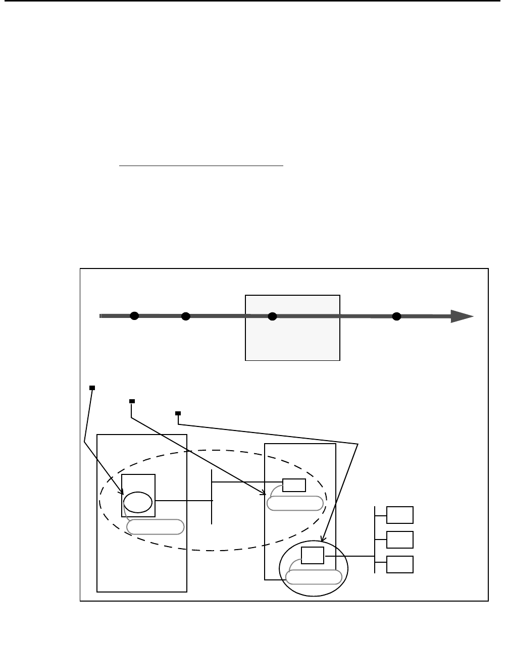
Installing Avaya Computer Telephony Server Software
60 Installation Guide
Planning Your Installation
Installing the Avaya Computer Telephony software represents a continuation of the switch-
specific activities described in Chapter 2. Planning your installation represents the
transition from Phase 1 to Phase 2 (see Figure 3-1). During this stage, the activities are as
follows:
●Gather the necessary information
●Determine the requirements of your configuration
- If you are installing Avaya Computer Telephony in a NAT or a Firewall environment,
see Implementing a Firewall Strategy on page 34
●Determine the type of installation — initial Installation or upgrade
●Make sure your platform can support Avaya Computer Telephony
Each of these activities is described in the next part of this chapter.
Figure 3-1: “CTI — Planning Your Server Installation”
Administer
DEFINITY
Install
Avaya CT
S
Install
Client
Software
Computer Telephony Integration
Phase 1 Phase 2 Phase 3
NIC
MAPD
DLG
Phase 2 involves gathering host names or IP addresses:
the DLG (on the MAPD)
the NIC on the Avaya CT Server that communicates with the DLG
NIC
TASK 1
192.168.25.20
192.168.25.10
Avaya CT Server
DEFINITY
Administer
DLG
TASK 2
Clients
176.108.25.20
the NIC on the Avaya CT Server that communicates with clients
Server Software

Planning Your Installation
Issue 1 October 2003 61
Gather the Necessary Information
The TCP/IP addressing information that is administered during DLG administration is
particularly relevant to installing the Telephony Services software (see Task 2: DLG
Administration on page 47). Make sure you have the following addressing information
before you start the Avaya Computer Telephony server software installation procedure.
●The IP address of the DLG. The default is 192.168.25.10, but it is highly likely that this
has been changed to conform to your network addressing requirements.
●The IP address that the DLG administrator assigned to the Avaya Computer Telephony
server. The default is 192.168.25.20. Again, it is highly likely that this IP address has
been changed to conform to your network addressing requirements. This IP address
refers to the Network Interface Card, on the Avaya Computer Telephony Server, that
communicates with the DLG. It is not the IP address of the NIC, on the Avaya Computer
Telephony server, that communicates with clients.
●The host name or IP address that was assigned to the Avaya Computer Telephony
server.
Determine the Requirements of Your Configuration
Determining the requirements of your configuration involves identifying the Avaya
Computer Telephony software components you are going to implement. Basically this
comes down to one question: “does this configuration support both the Tserver (Telephony
Services Server) and the CVLAN (CallVisor PC Local Area Network) applications?" See
Chapter 5: Using CVLAN for information about CVLAN.
Determine the Type of Installation -- Initial Installation or Upgrade
If you are upgrading an earlier release of Avaya Computer Telephony, see Guidelines for
Upgrading Avaya Computer Telephony on page 64.
Make Sure Your Platform Can Support Avaya Computer Telephony
See Table 3-1: Server Hardware on page 62 and Table 3-2: Server Software on page 63
to make sure that you have the appropriate hardware and software.

Installing Avaya Computer Telephony Server Software
62 Installation Guide
Avaya Computer Telephony Hardware and Software
Requirements
Table 3-1 lists the server hardware requirements for Telephony Services and CVLAN
server which is based on Contact Center size (i.e number of Agents).
Table 3-1: Server Hardware
Low to Low Mid-
End Contact
Center (10-200
Agents)
Mid-End Contact
Center (200-500
Agents)
High-End Contact
Center (500-2500
Agents)
CPU Pentium III 350MHZ
or higher Pentium® III
500MHZ or higher Pentium® III
700MHZ or higher
RAM 256MB or higher 512MB or higher 512MB or higher
Network
Connections For a standard
installation, 2
network interface
card(s) are
recommended:
●one for the G3PD
●one for client
access
If your configuration
uses NAT or a
Firewall, see
Implementing a
Firewall Strategy on
page 34
For a standard
installation, 2
network interface
card(s) are
recommended:
●one for the G3PD
●one for client
access
If your configuration
uses NAT or a
Firewall, see
Implementing a
Firewall Strategy on
page 34
For a standard
installation, 2
network interface
card(s) are
recommended:
●one for the G3PD
●one for client
access
If your configuration
uses NAT or a
Firewall, see
Implementing a
Firewall Strategy on
page 34
Drives CD-ROM drive: 3.5-
inch floppy drive (for
license and
authorization disks)
CD-ROM drive: 3.5-
inch floppy drive (for
license and
authorization disks)
CD-ROM drive: 3.5-
inch floppy drive (for
license and
authorization disks)
Disk Space1
1. Each disk space requirement is an approximation. The amount of disk space required also depends
on other factors such as, the number of users, types of activity performed, and number and/or size
of the trace files.
300MB Hard Drive 300MB Hard Drive 300MB Hard Drive
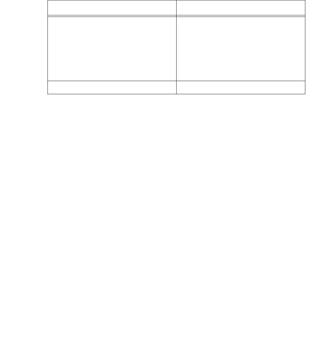
Planning Your Installation
Issue 1 October 2003 63
Table 3-2 lists the server software requirements for Telephony Services and CVLAN
Table 3-2: Server Software
Software Description
Operating System Any of the following:
●Windows NT 4.0 (Server is
recommended)
●Windows NT Service Pack 6a or
later, available from Microsoft
●Windows 2000 with Service Pack 2
●Windows XP
●Windows 2003
Network Software TCP/IP protocol stack

Installing Avaya Computer Telephony Server Software
64 Installation Guide
Guidelines for Upgrading Avaya Computer
Telephony
Although the installation procedure in this chapter depicts an initial installation, you follow
the same basic procedure to upgrade. If you are upgrading, however, be sure to review
this section before you upgrade your Avaya Computer Telephony software.
●If you install any Service Packs or if you upgrade Windows NT, Windows 2000,
Windows XP software on a machine that already has Telephony Services software
installed, you must reinstall all of the Telephony Services software components,
including the Telephony Services Security Database (SDB).
●If you are upgrading (or migrating) from a NetWare Telephony Server to a Windows NT,
Windows 2000, Windows XP Telephony Server, see Appendix C: Migrating your
Security Database.
●Uninstalling the Telephony Server software is not recommended when upgrading from
an earlier release unless the new software will be installed in a different directory on the
server. (Information about the Telephony Server is stored in the Windows NT, Windows
2000, Windows XP Registry. These registry settings are removed when the software is
uninstalled.)
●Stop Telephony Services and the Logging Service before you attempt to install the new
software. See Manually Stopping Telephony Services on page 89.
●Overwrite your previous installation of Avaya Computer Telephony. If the previous
installation did not use the default destination folders (C:\Program Files\Avaya\CT) for
these components, be sure to specify the destination folders that were used during the
initial installation. Steps 7 and 8 provide a Destination Directory dialog box that enables
you to browse to, and specify another destination for Avaya Computer Telephony server
files.

Guidelines for Upgrading Avaya Computer Telephony
Issue 1 October 2003 65
●Do not re-install the Security Database for Telephony services. If you are upgrading, the
checkbox for “Security Database for Telephony Services” is not checked on the Server
Setup dialog box (Step 3). Setup detects the previous installation of the Telephony
Services Security Database (also referred to as Btrieve).
If you select this checkbox during an upgrade, Setup detects the previous installation
of Btrieve and displays a warning box indicating that you have Btrieve Workstation
v6.15 installed on this machine. In this case, you can continue with the installation —
you do not need to exit.
Other Things to Consider for an Upgrade
You can take advantage of current settings or provisions that were effected in a prior
installation.
●userIDs/accounts with administrative permissions
At Step 12, on the Select Tserver Administrator dialog box, you can use the pull-
down menu to see a list of all the user IDs/accounts with administrative permissions
on the Telephony Server.
- Select the default user ID/account that the Telephony Server should use when it
starts. Then click Next.
The Telephony Server administrative user ID/account that you choose here
becomes the default user ID/account for first time use of administration software
tools (i.e., Telephony Services Administrator [TSA32] and Telephony Services
Maintenance [TSM32]).

Installing Avaya Computer Telephony Server Software
66 Installation Guide
Specialized Installations
The term specialized installations refers to effecting Avaya Computer Telephony
installations that do not require all of the Avaya Computer Telephony software
components. This section describes two kinds of specialized installations.
●Avaya Computer Telephony without the Telephony Services Security Database
You can elect not to install the Telephony Services Security database if you already
have a database that serves your applications’ needs. To install Avaya Computer
Telephony without the Telephony Services Security Database, make sure that the
checkbox for "Telephony Services Security Database" is unchecked (at Step 5 of the
installation procedure). If you implement an installation of Avaya Computer Telephony
without the Telephony Services security database, you do not have access to the
Telephony Services Administration capabilities.
●Avaya Computer Telephony without the G3PBX Driver
If you are developing software applications and you do not have access to a DEFINITY
switch (and you are using the DEFINITY simulator, for example) be sure that the
checkbox for "DEFINITY G3 PBX Driver and CVLAN" is unchecked (at Step 4).

Before You Install the Avaya Computer Telephony Server Software
Issue 1 October 2003 67
Before You Install the Avaya Computer Telephony
Server Software
Here are some tips for effecting a smooth, uninterrupted installation.
●Determine the IP address of the Telephony Server.
In the Enter Information dialog box (Step 11), the Setup program asks you to specify
the IP address of the server. This IP address refers to the NIC that the Tserver uses for
communicating with its clients (as opposed to the IP address for the NIC designated for
the G3 PBX Driver). To locate this IP address, use this procedure.
Click Start, point to Settings, click Control Panel, double-click Network, click
Protocols (tab), select TCP/IP Protocol, and click Properties.
●Know the locations of the installation-specific readme files.
Readme file notifications are embedded in the installation procedure. To avoid
disruption during installation, you can clear the checkboxes for viewing the readme
files. Review the readme files after installation.
- Security Database Readme file
From the Windows NT, Windows 2000 or Windows XP desktop, click Start, point to
Programs, click Btrieve Technologies Database, and double-click Btrieve
Workstation Engine Readme
- Tserver Readme file.
From the Windows NT, Windows 2000 or Windows XP desktop, click Start, point to
Programs, Avaya Computer Telephony, TS Readme
- G3PBX Driver Readme
From the Windows NT, Windows 2000 or Windows XP desktop, click Start, point to
Programs, Avaya Computer Telephony, DEFINITY G3 PBX, and click G3PBX
Driver Readme
●Have license disks (or authorization disks) for Telephony Services and the
G3PBX Driver handy. Setup prompts you for them during the installation procedure.
●Unless you are an experienced administrator, effect a default installation.
If you are an experienced administrator and you want to override the defaults, these
capabilities are available.
- The Destination Directory dialog boxes allow you to customize your directory
settings. Unless you are able to effect a customized installation, accept the defaults.
- The G3PBX Driver Configuration dialog box allows you to carry out administrative
tasks.
●You can specify the DEFINITY G3PBX Driver IP address and add links.

Installing Avaya Computer Telephony Server Software
68 Installation Guide
●If you are setting up CVLAN, you can click the ADMIN button and add CVLAN
clients. See ‘‘Adding a CVLAN Client’’ on page -128 of this document.
Alternatively, you can make G3PD changes after completing the installation procedure.
Use either G3 PBX Driver Configuration Utility or the G3 PBX Link Change Utility. See
Chapter 2 of the Avaya Computer Telephony 1.3 G3 PBX Driver and CVLAN
Administration and Maintenance Guide (DEFNETM.PDF).
Avaya Computer Telephony Installation Guidelines
When installed in an NT Domain, Avaya Computer Telephony should be installed as an
Application Member Server. Although Avaya Computer Telephony can be installed on a
Domain Controller it is not recommended.
Avaya Computer Telephony should not be installed on a server that performs any of the
following functions;
●Print Server
●Web Server
●FTP Server
●Fax Server
●RAS Server
●Router
●Voice/Screen Call Recorder Server
●Intelligent Voice Response Server
Avaya Computer Telephony should not be installed on a server that is running applications
that use a Java Virtual Machine (Microsoft, Sun, or IBM).
Avaya Computer Telephony should not be installed on a server that is running Microsoft
SQL or any other database.
Avaya Computer Telephony can be Co-Resident with the following Avaya Applications/
Platforms.
●BCMSVu
●Avaya Computer Telephony Internet Solutions
●Avaya Call Service
●Avaya Interaction Center
●Avaya Enterprise Manager
●DEFINITY Anywhere

Avaya Computer Telephony Installation Guidelines
Issue 1 October 2003 69
●Avaya Web Collaboration
●Avaya Messaging
●Avaya Unified Communication Center
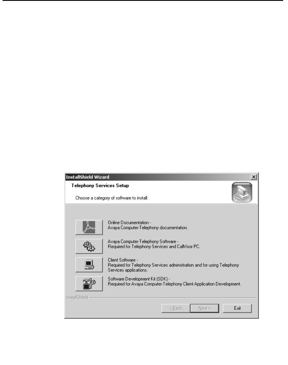
Installing Avaya Computer Telephony Server Software
70 Installation Guide
Procedure for Initial, Default Installation of Avaya
Computer Telephony Server Software
Follow these steps for an initial installation Avaya Computer Telephony Server Software.
You can click Cancel or Exit at any time to exit from the Setup program.
Note:
Note: This procedure depicts the CD-ROM drive ID as D:\. Substitute D with the
appropriate letter as necessary.
1. Log on to the Windows NT, Windows 2000 or Windows XP server as a user with
administrator-equivalent permissions.
2. Insert the CD into the CD-ROM drive.
(When Windows NT, Windows 2000 or Windows XP is using the Explorer shell, the
Setup program runs automatically if you have not disabled the AutoRun feature).
3. (Applies only if AutoRun is disabled) Click Start, then click Run. In the Run dialog box,
enter D:\WININST\SETUP.EXE (or Browse to it on the CD) to start the Setup
program.
Setup displays the Telephony Services Setup dialog box.

Procedure for Initial, Default Installation of Avaya Computer Telephony Server Software
Issue 1 October 2003 71
4. Click the button for Avaya Computer Telephony Software.
Setup displays the Server Setup dialog box. For an initial installation, all server
components are selected by default.
Installing Avaya Computer Telephony Server Software
72 Installation Guide
5. click Next to accept the default settings and continue with the installation.
Setup displays the message, “Installation in progress, please wait...”, followed by the
Welcome dialog box for the Telephony Services Security Database (Btrieve
Workstation Engine v6.15).
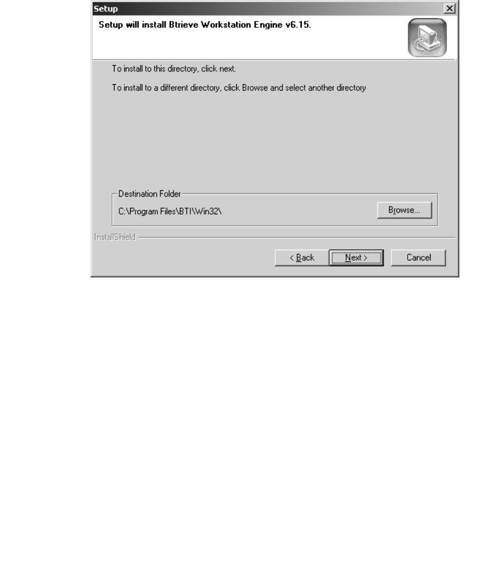
Procedure for Initial, Default Installation of Avaya Computer Telephony Server Software
Issue 1 October 2003 73
6. Click Next to continue with the installation.
Setup displays a dialog box indicating that Setup will install Btrieve Workstation Engine
v6.15 in the default destination folder, C:\Program Files\BTI\Win32\.
7. Click Next to accept the default destination folder and continue with the installation.
Installing Avaya Computer Telephony Server Software
74 Installation Guide
Setup displays the Installation Complete dialog box, indicating that Setup has finished
installing Btrieve on your computer.
8. Click Finish (you have finished installing Btrieve) and continue with the installation to
install Telephony Services on your computer.

Procedure for Initial, Default Installation of Avaya Computer Telephony Server Software
Issue 1 October 2003 75
Setup displays the message, “Installation in progress, please wait...”, followed by the
Welcome dialog box for the Telephony Services Setup program.
9. Click Next to continue with the installation.
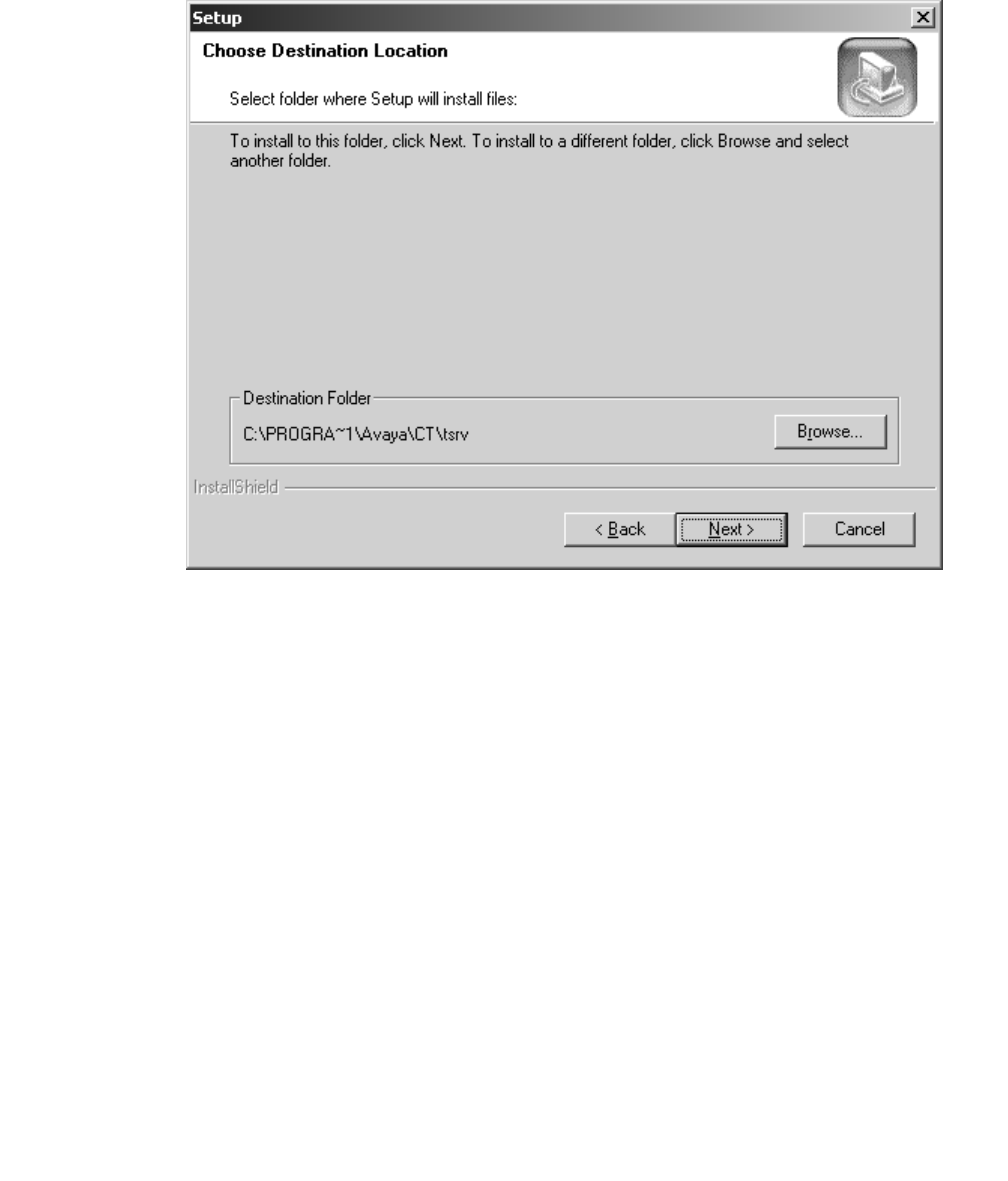
Installing Avaya Computer Telephony Server Software
76 Installation Guide
Setup displays the Choose Destination Location dialog box indicating that Setup will
install the Telephony Services files in the default destination folder, C:\Program
Files\Avaya\CT\tsrv.
10. Click Next to accept the default destination folder and continue with the installation.
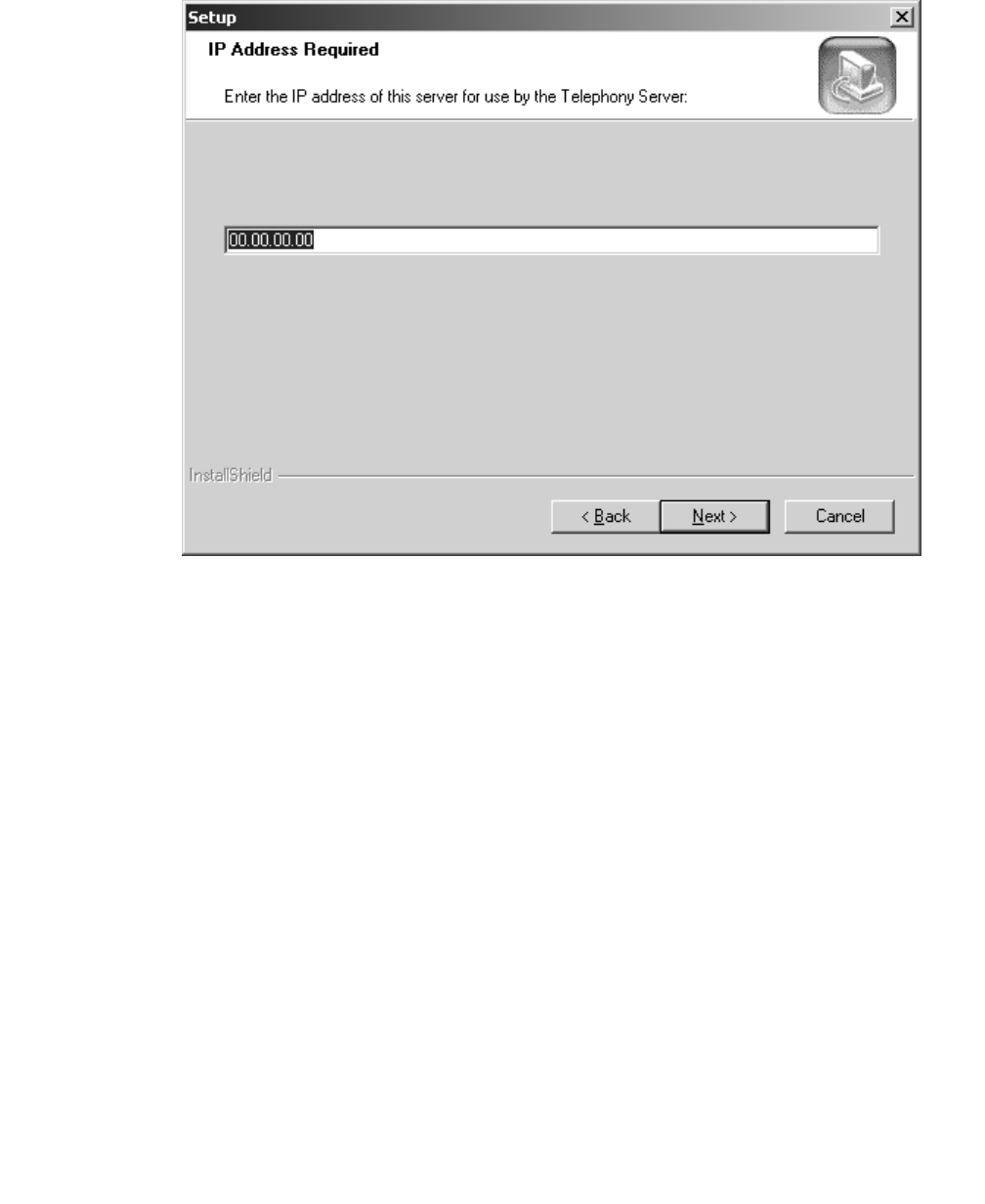
Procedure for Initial, Default Installation of Avaya Computer Telephony Server Software
Issue 1 October 2003 77
Setup displays the IP Address Required dialog box.
11. Enter the IP address for this Telephony Server (which is the IP address of the NIC that
the Telephony Server uses for communicating with TSAPI clients), and click Next.
Note:
Note: If you are configuring the Telephony Server in a firewall environment, see
one of the following documents, based on the location of your firewall.
●If your firewall is between the client and the Avaya Computer Telephony
server, see Chapter 6 of the Telephony Services Administration and
Maintenance Guide (NETMANGD.PDF).
●f your firewall is between the Avaya Computer Telephony server and
MultiVantage, see Chapter 2 of the G3PBX Driver and CVLAN Administration
and Maintenance Guide (DEFNETM.PDF).
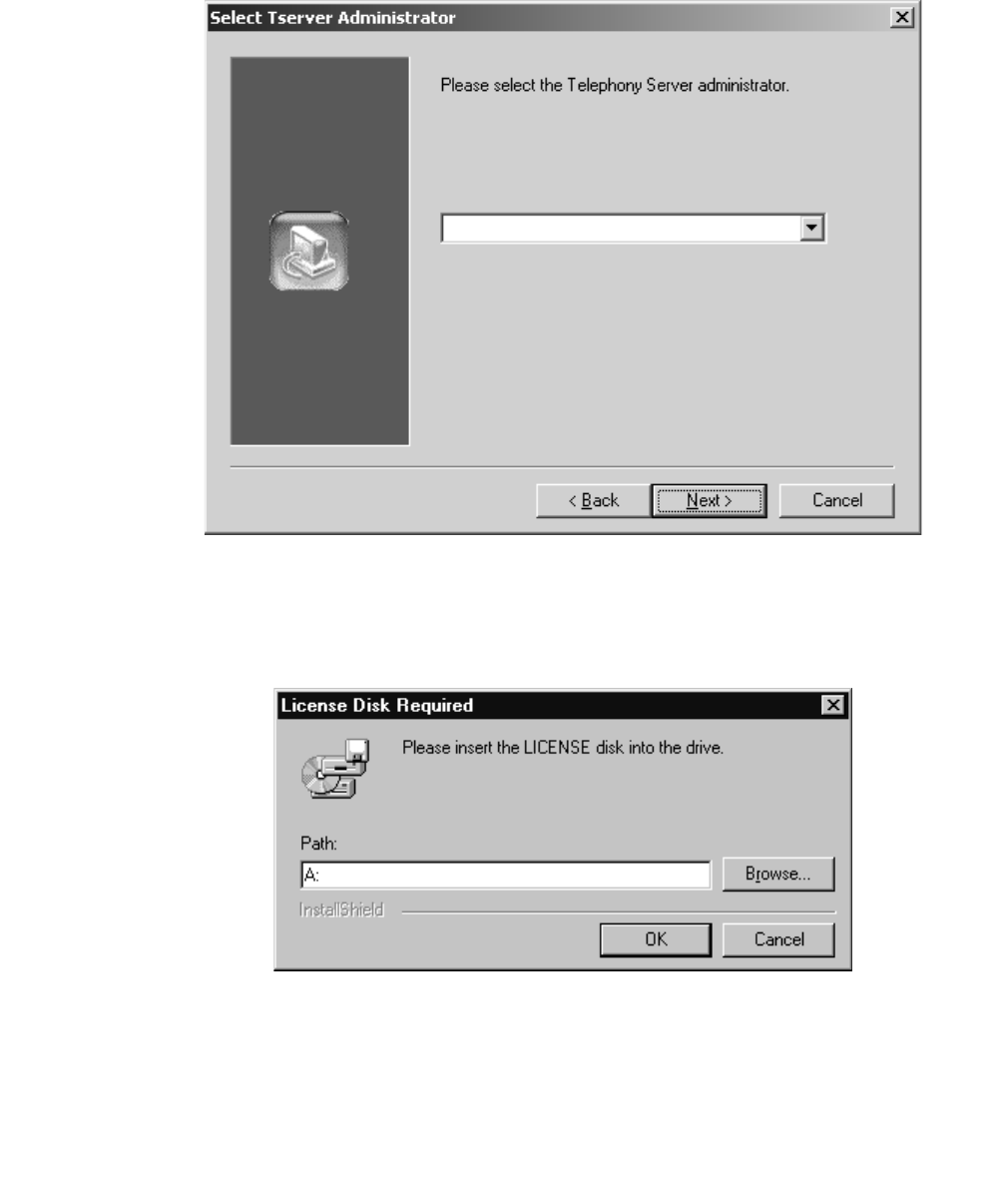
Installing Avaya Computer Telephony Server Software
78 Installation Guide
Setup displays the Select Tserver Administrator dialog box with the list box displaying
Administrator.
12. Click Next to continue with the installation.
Setup copies the files and installs the Telephony Server software (as Windows NT,
Windows 2000 or Windows XP services) and prompts you to insert the license disk.
Administrator
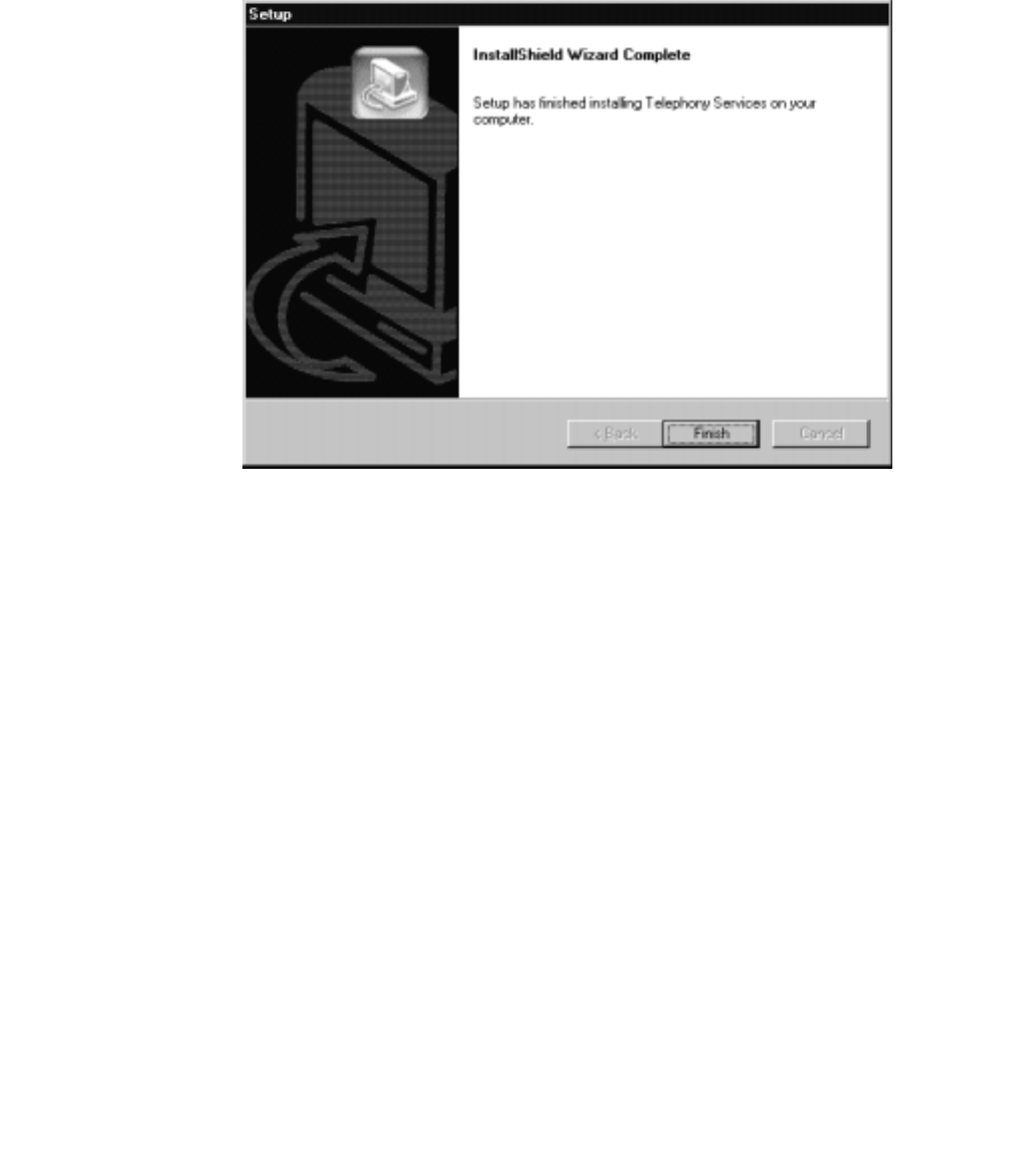
Procedure for Initial, Default Installation of Avaya Computer Telephony Server Software
Issue 1 October 2003 79
13. Insert the disk in the appropriate drive on the server PC, and click OK.
After copying the license file, Setup displays the InstallShield Wizard Complete dialog
box, indicating that Setup finished installing Telephony Services on your computer.
14. Click Finish (you have finished installing Telephony Services software) and continue
with the installation to install the DEFINITY G3PBX Driver on your computer.

Installing Avaya Computer Telephony Server Software
80 Installation Guide
Setup displays the message, “Installation in progress, please wait...” followed by the
Welcome dialog box for the DEFINITY G3 PBX Driver Setup. (Setup installs the
CVLAN Server during this phase of installation).
15. Click Next to continue with the installation.
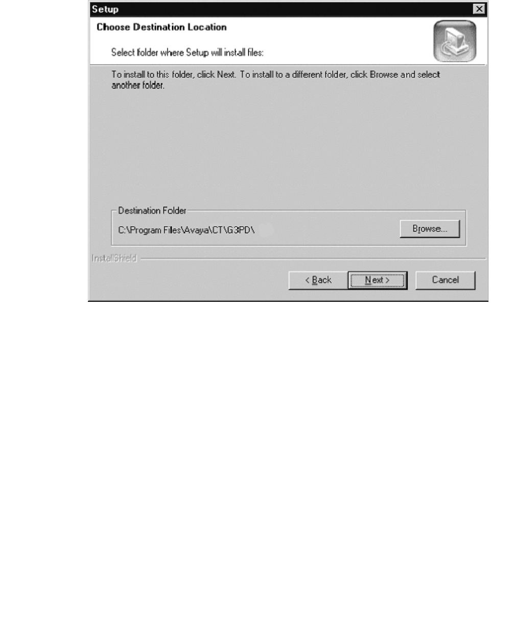
Procedure for Initial, Default Installation of Avaya Computer Telephony Server Software
Issue 1 October 2003 81
Setup displays the Choose Destination Location dialog box indicating that Setup will
install the G3PBX Driver in the default location, C:\Program Files\Avaya\CT\G3PD\.
16. click Next to accept the default destination folder and continue with the installation.
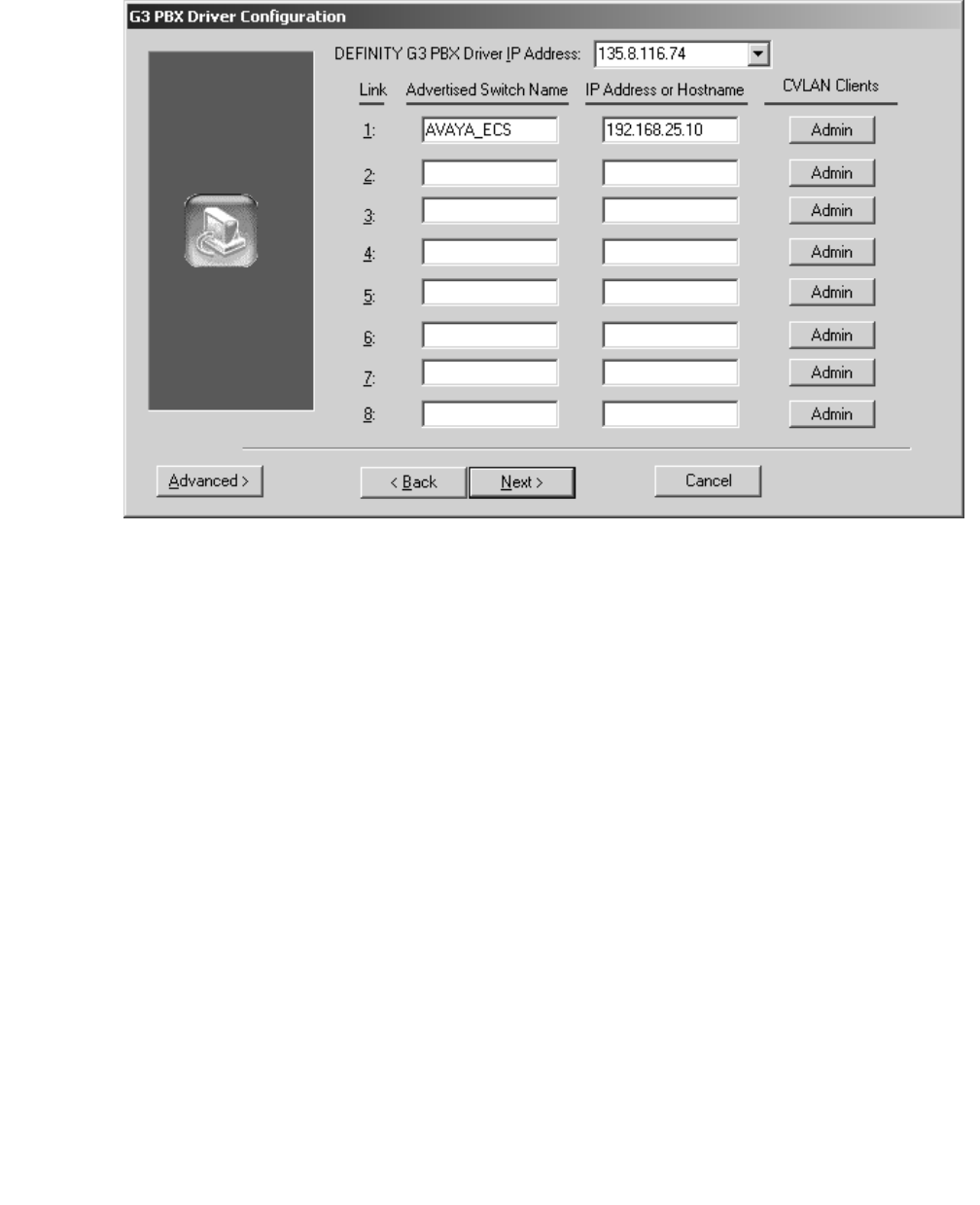
Installing Avaya Computer Telephony Server Software
82 Installation Guide
Setup displays the DEFINITY G3 PBX Driver Configuration dialog box.
17. Complete the G3PBX Driver configuration box as follows,
●in the DEFINITY G3 PBX Driver IP Address field, enter the IP address of the NIC
used for communicating with the switch.
●In the Advertised Switch Name field, enter the appropriate name for the switch you
are connecting to (the default name is Avaya_ECS).
●in the IP Address or Host Name field, enter the appropriate IP address for the
switch you are connecting to (this the IP address of the Ethernet interface for the
DEFINTY LAN Gateway).
Note:
Note: If you are installing Avaya Computer Telephony in a firewall environment,
where the firewall is between MultiVantage and the Avaya Computer
Telephony Server, see Chapter 2 of the G3PBX Driver and CVLAN
Administration and Maintenance Guide (DEFNETM.PDF).
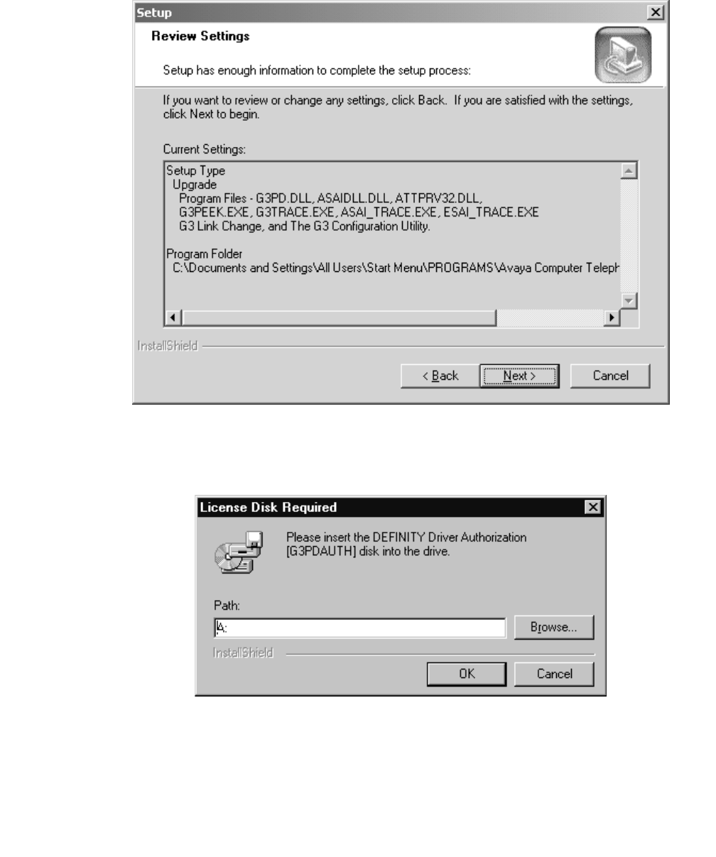
Procedure for Initial, Default Installation of Avaya Computer Telephony Server Software
Issue 1 October 2003 83
Setup displays the Review Settings dialog box with the current settings for the
installation.
18. Click Next to continue with the installation.
Setup displays the License Disk Required dialog box.
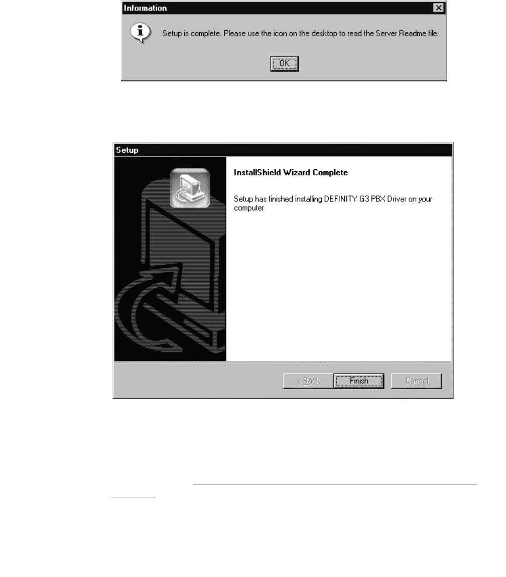
Installing Avaya Computer Telephony Server Software
84 Installation Guide
19. Insert the DEFINITY Driver Authorization [G3PDAUTH] disk in the appropriate drive on
the server PC, and click OK.
After copying the G3PDAUTH file, Setup displays the following Information box,
indicating that Setup is complete.
20. Click OK to continue with the installation.
Setup displays the InstallShield Wizard Complete dialog box.
21. Click Finish to complete the Installation of the Avaya Computer Telephony Server
software (This step stops the Setup program).
Note:
Note: Make sure you review each of the readme files associated with the
installation. See Before You Install the Avaya Computer Telephony Server
Software on page 67 for locations of the readme files.

Perform Initial Restart
Issue 1 October 2003 85
Perform Initial Restart
After installing the Avaya Computer Telephony software you do not have to reboot the PC.
To start using Avaya Computer Telephony server software follow these steps.
1. Click Start point to Programs, Avaya Computer Telephony, and click TS Controller.
2. From the TS Controller dialog box, click Start.
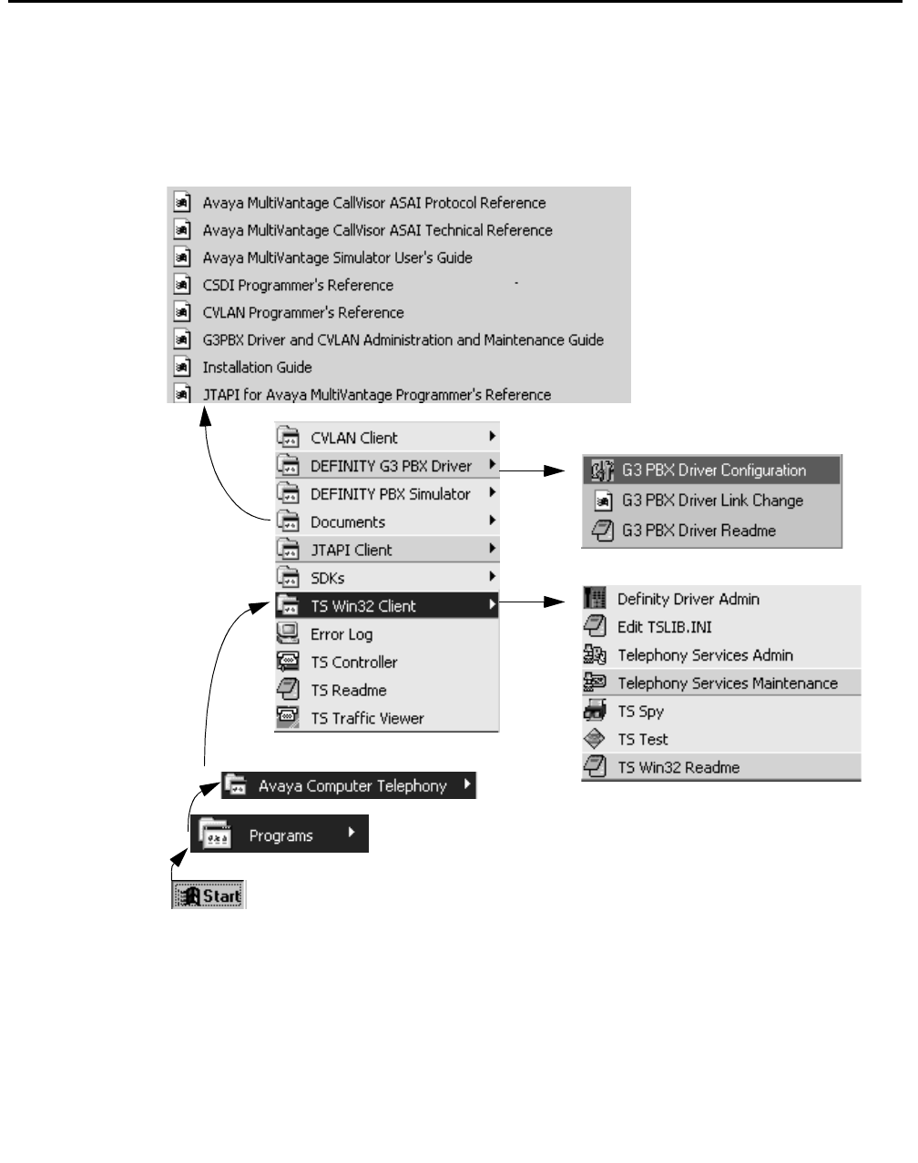

Basic Maintenance Tasks
Issue 1 October 2003 87
Basic Maintenance Tasks
This section describes the following basic maintenance tasks for Telephony Services:
●Starting and Stopping the Telephony Services Software
●Manually Stopping Telephony Services
●Removing Software
Starting and Stopping the Telephony Services Software
This section describes the following tasks.
●starting Telephony Services
- enabling automatic startup and recovery of telephony services
●performing manual start and enabling automatic startup and recovery
●manually stopping Telephony Services
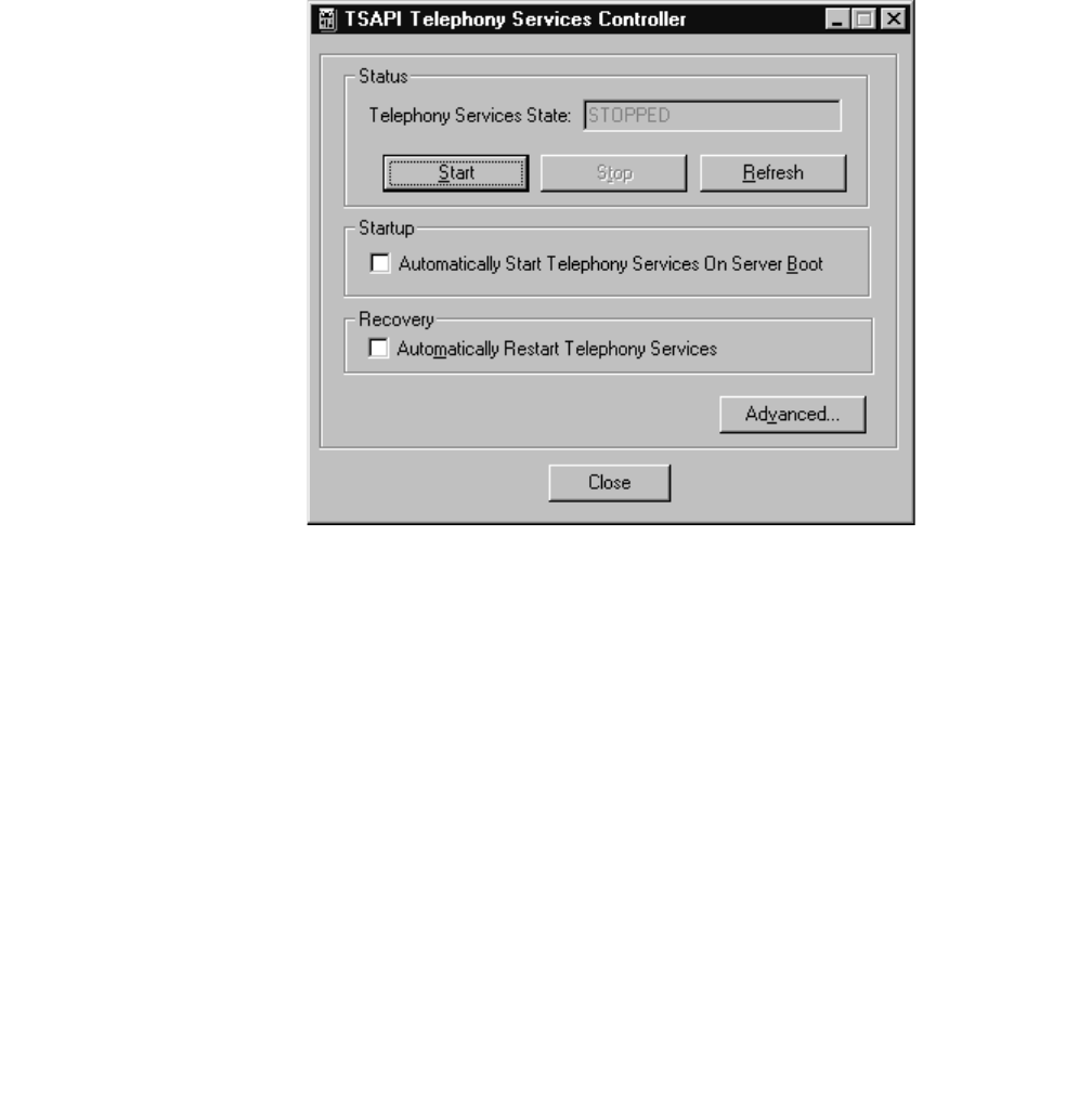
Installing Avaya Computer Telephony Server Software
88 Installation Guide
Starting Telephony Services
You have already encountered this procedure in the context of the installation (‘‘Perform
Initial Restart’’ on page -85). Recall that when the Telephony Services server software (the
Telephony Server, or Tserver and the CVLAN server) is initially installed, it is in the
“STOPPED” state and must be manually started.
Follow these steps to start the Telephony Services server.
1. Click Start, point to Programs, Avaya Computer Telephony, and click TS Controller.
2. Click Start to start Telephony Services.
Telephony Services starts the Tserver and the CVLAN server and Information box
displays.
3. Click OK to dismiss the information box and return to the Telephony Services
Controller dialog box.
On the Telephony Services controller dialog box, under “Status,” the Telephony
Services state is listed as “RUNNING.”
4. Click Close to exit the Telephony Services Controller dialog box.
This completes the procedure to manually start Telephony Services software.
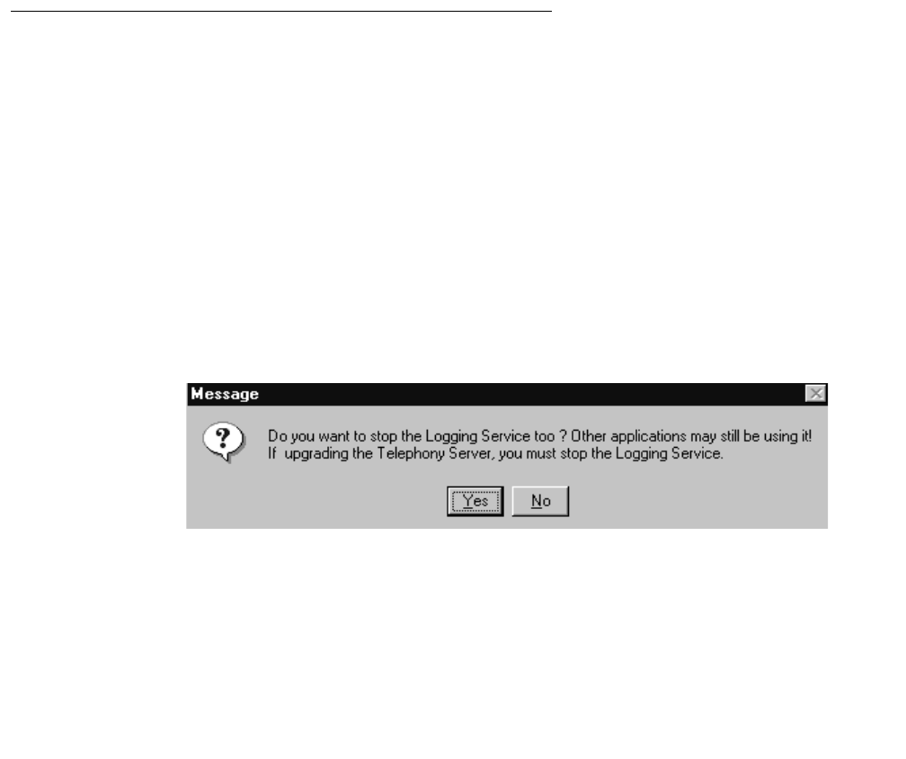
Basic Maintenance Tasks
Issue 1 October 2003 89
Enabling Automatic Startup and Recovery
This procedure is an extension of the previous procedure, ‘‘Starting Telephony Services’’
on page -88, with steps for enabling automatic Startup and Recovery. You are
recommended to effect automatic startup and recovery.
1. Click Start, point to Programs, Avaya Computer Telephony, and click TS Controller.
The Tserver displays the TS Controller dialog box.
2. Under Startup, click the checkbox next to “Automatically Start Telephony Services On
Server Boot.”
3. Under Recovery, click the checkbox next to “Automatically Restart Telephony
Services.”
4. Click Close to exit the Telephony Services Controller dialog box.
This completes the procedure for enabling automatic startup and recovery.
Manually Stopping Telephony Services
Follow this procedure to manually or explicitly stop Telephony Services and the CVLAN
server.
1. Click Start, point to Programs, Avaya Computer Telephony, and click TS Controller.
2. From the Telephony Services Controller dialog box, click Stop.
The Telephony Services and CVLAN server are stopped, and an Information box
displays.
3. Click OK
The operating system displays a message box that prompts you to stop the Logging
Service.
4. Click Yes to stop the logging service.
5. From the Telephony Services Controller dialog box, click Close to exit the Telephony
Services Controller.

Installing Avaya Computer Telephony Server Software
90 Installation Guide
Removing Software
Use the standard Windows procedure described below to remove the following server
components.
●Btrieve Workstation Engine v6.15.
●Telephony Services
Note:
Note: Before you can remove the Telephony Services server software (Tserver
and CVLAN server) you must unregister telephony services. Follow the
procedure in ‘‘Reinstalling Telephony Services Server Software’’ on page -
90 (which includes the standard Windows procedure for removing
Telephony Services).
●DEFINITY G3 PBX Driver
Procedure to Remove Programs
1. From the desktop click Start, point to Settings and click Control Panel.
2. From the Control Panel, click Add/Remove Programs.
3. Windows displays the Add/Remove Programs Properties dialog box.
4. Select the appropriate module you wish to uninstall (Avaya Computer Telephony
Services, Btrieve, or Avaya Computer Telephony ECS Driver), and click Add/Remove.
5. Windows displays the Confirm File Deletion box, asking you to confirm that you want to
completely remove the software program and all of its components.
6. Click Yes.
The uninstall program removes the software and displays an Information box indicating
that the program and all of its components have been removed.
7. Click OK.
This completes the procedure to remove a software program.
Reinstalling Telephony Services
Server Software
If you need to reinstall the Telephony Services software, it is recommended that you do not
uninstall the currently installed Telephony Services software before performing the
reinstallation. This is because many of the parameters used by Telephony Services are
stored in the Windows NT, Windows 2000 or Windows XP registry. When the software is
uninstalled, these parameters are also removed.

Basic Maintenance Tasks
Issue 1 October 2003 91
Note:
Note: Although Windows NT, Windows 2000 or Windows XP registry information is
removed when you uninstall the Telephony Services software, the log files
(error log file, message trace file, performance log, traffic log, and SDB log
file) are not removed. When the Telephony Server is restarted after
reinstallation, new log file information starts at the top of the files. Any
information previously contained in the files is overwritten with the new
information.
To reinstall the Telephony Service software, follow the steps in Procedure for Initial, Default
Installation of Avaya Computer Telephony Server Software.

Installing Avaya Computer Telephony Server Software
92 Installation Guide

Issue 1 October 2003 93
Chapter 4: Installing Avaya Computer
Telephony TSAPI Client Software
This chapter describes installation related procedures for Avaya Computer Telephony,
Telephony Services Application Programming Interface (TSAPI) clients. It includes the
following topics:
●Avaya Computer Telephony Clients and Private Data Versions on page 94
●Planning Your Installation on page 94
●TSAPI Client Hardware and Software Requirements on page 96
●Before You Install the Avaya Computer Telephony TSAPI Client Software on page 100
●Installing the Windows Client Software on page 101
●Installing TSAPI Solaris Sparc Client Software on page 110
●Installing UnixWare Client Software on page 112
●Installing HP-UX Client Software on page 116
●Removing Telephony Services Client Software on page 119

Installing Avaya Computer Telephony TSAPI Client Software
94 Installation Guide
Avaya Computer Telephony Clients and Private Data
Versions
In the context of general information about Avaya Computer Telephony, Chapter
1: Learning About Avaya Computer Telephony provides Table 1-1 on page -35, which
associates Avaya Computer Telephony, Client Application platform operating systems with
the level of DEFINITY Private Data Versions that they support.
Briefly summarized, Table 1-1 on page -35 states that the Avaya Computer Telephony
Windows 32-bit client platform and the Avaya Computer Telephony UnixWare client
platform supports all versions of DEFINITY Private Data up to Private Data Version 6.
Planning Your Installation
Installing the Avaya Computer Telephony TSAPI client software represents a continuation
of the server-specific activities described in Chapter 3. Planning your installation
represents the transition from Phase 2 to Phase 3 (see Figure 4-1). During this transitional
state, the activities are as follows.
●Make sure that your client workstations can support Avaya Computer Telephony (see
‘‘Avaya Computer Telephony Client Hardware and Software Requirements’’ on page -
96)
●Determine if this is an upgrade or an initial installation
●Determine how you intend to distribute the software
- CD-ROM
- Network Drive
Each of these activities is described in the next part of this chapter.
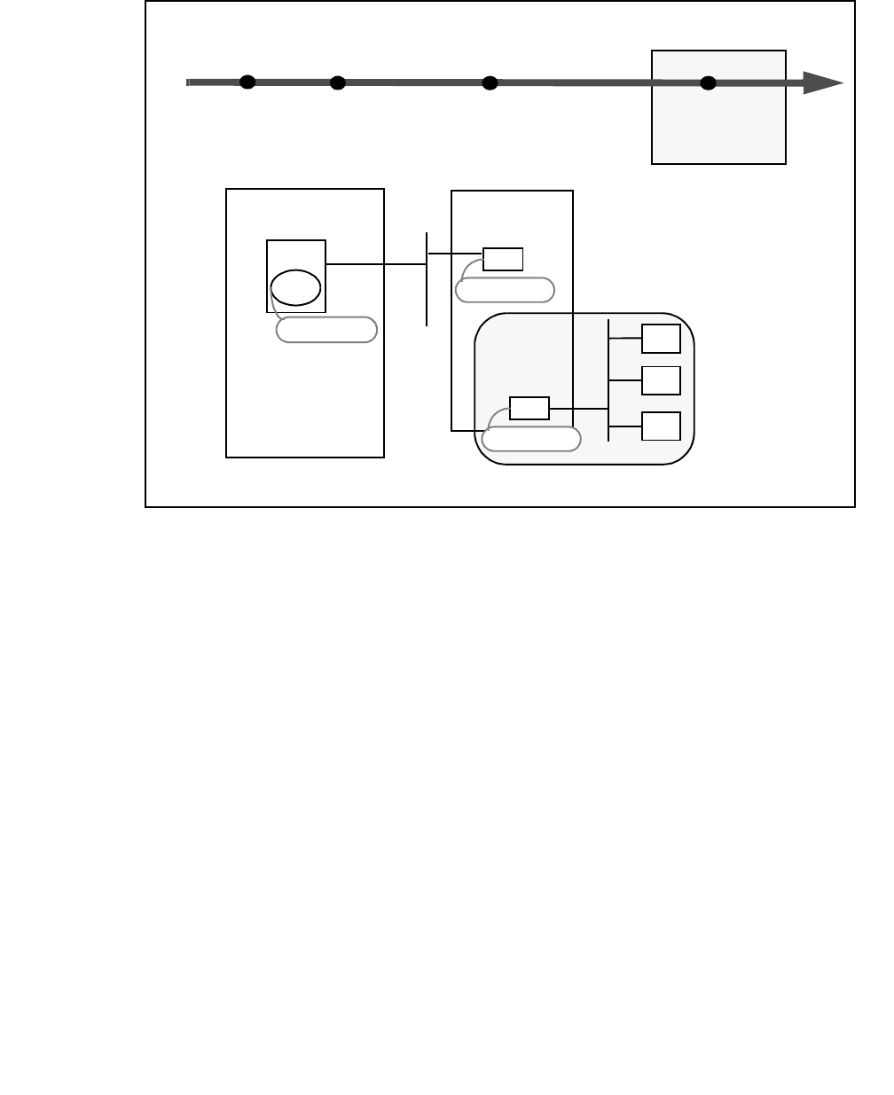
Planning Your Installation
Issue 1 October 2003 95
Figure 4-1: The CTI Continuum — Planning Your Client Installation
Administer
DEFINITY
Install
Avaya CT Server
Software
Install
Client
Software
Computer Telephony Integration
Phase 1 Phase 2 Phase 3
NIC
MAPD
DLG
TASK 1
192.168.25.20
192.168.25.10
Avaya CT Server
DEFINITY
Administer
DLG
TASK 2
Administrative
Workstation
NIC
176.108.25.20
Client
Basic
Workstation
Client
Basic
Workstation
Client

Installing Avaya Computer Telephony TSAPI Client Software
96 Installation Guide
TSAPI Client Hardware and Software Requirements
Tables 4-1 and 4-2 list the TSAPI client hardware and software requirements.
Avaya Computer Telephony Client Hardware and
Software Requirements
Table 4-1: Windows-Based Client Hardware and Software Requirements
CPU 486 or Pentium recommended
RAM Windows 95
8 MB required; 16 MB recommended
Windows NT, Windows 2000, Windows XP or
Windows 98
16 MB required; 24-32 MB recommended
Free Memory Installing and running Telephony Services and
CVLAN on a Windows client requires 500 KB of
free memory.
Disk Space 500 KB of disk space is required, or 1.5 MB if the
Telephony Services Administration software is
also installed.
Win32 Client
Platform
Operating
Systems
(The Win32 client
platform operating
systems (i.e.,
Windows 95,
Windows 98,
Windows NT,
Windows 2000,
Windows XP)
Win32 clients:
Windows 95
Microsoft TCP/IP or equivalent 32-bit Winsock
TCP/IP transport provider
Windows 98
Microsoft TCP/IP or equivalent 32-bit Winsock
TCP/IP transport provider
Windows NT
Windows NT 3.51 or 4.0 (Workstation or Server);
Microsoft TCP/IP or equivalent 32-bit Winsock
TCP/IP transport provider
Windows 2000
Windows XP

TSAPI Client Hardware and Software Requirements
Issue 1 October 2003 97
UnixWare Client Hardware and
Software Requirements
HP-UX Client Hardware and Software Requirements
TSAPI Solaris Client Hardware and
Software Requirements
Table 4-2: UnixWare Client Hardware and Software Requirements
CPU 386 or higher required; 486 or Pentium
recommended
RAM UnixWare Personal Edition
8 MB required
UnixWare Application Server
12 MB required
Disk Space 300 KB
Operating
Systems UnixWare 1.x
UnixWare 2.0x
Table 4-3: HP-UX Client Hardware and Software Requirements
CPU HP 9000 Series 700 or Series 800 machine
RAM 32 Mbytes required
Disk Space 1 Mbyte
Operating
System HP-UX
Table 4-4: TSAPI Solaris Client Hardware and Software Requirements
Disk Space 1.2 MB
Processor SPARC
Operating
Systems Solaris 2.5.1, Solaris 8

Installing Avaya Computer Telephony TSAPI Client Software
98 Installation Guide
Telephony Services Client Software
Telephony Services client software for Windows consists of the following components. (For
information about CVLAN clients, see Chapter 5: Using CVLAN.)
●Telephony Services client software — allows TSAPI applications to communicate with
the Telephony Server.
●Client administration software — enables the system administrator to perform specific
tasks. The Win32 client software includes administration and maintenance software for
the Telephony Server. The Win32 software also includes operation, administration, and
maintenance software for the DEFINITY G3 PBX Driver.
●DEFINITY G3 private data support libraries — allow TSAPI applications to take
advantage of DEFINITY G3-specific driver features that are available through private
data and escape services. This software is installed automatically as part of the client
installation procedure.
Once you have installed Telephony Services software on your client, you can easily access
the Telephony Services applications by creating a shortcut icon for each application. (Use
the “Create Shortcut icon” feature of Windows NT, Windows 2000, Windows XP, Windows
95, or Windows 98 to create the icons. Refer to your Windows documentation for details.)
Telephony Services Client Platforms
The Telephony Services client software can be installed on the following client platforms:
●Windows NT 3.51 workstation or server, Windows NT 4.0 workstation or server,
Windows 2000, Windows XP, Windows 95 or Windows 98.
- 32-bit (Win32) TSAPI applications use the 32-bit Telephony Services client software.
●UnixWare — The UnixWare client software comes in single-threaded (UnixWare 1.x)
and multi-threaded (UnixWare 2.0x) versions. For details on using the Link Status
command, see the “Link Status Command” section in Chapter 3 of Avaya Computer
Telephony 1.3 G3 PBX Driver and CVLAN Administration and Maintenance
(DEFNETM.PDF).
●Solaris Sparc - The Solaris client software can be installed on a Solaris SPARC client
workstation.
●HP-UX - The HP-UX client software can be installed on a client PC.

TSAPI Client Hardware and Software Requirements
Issue 1 October 2003 99
Client Administration Software Components
The Telephony Services client software includes Windows based administrative software
that allows the system administrator to maintain and operate the system. Follow these
guidelines before you install the client software:
●Identify the system administrator’s workstation. You will need to install the Windows-
based administrative software on an appropriate client workstation.
●Determine how you intend to distribute and install the client software (CD-ROM, disk,
and, if applicable, from the network server).
Client Administration Workstation
You can assign the PC designated as the Telephony Services server as the Administrative
Client workstation, or you can use a separate workstation on your LAN.
The client software includes the following applications that enable the system administrator
to perform specific tasks:
●Telephony Services Administrator (TSA32) is the client-based 32-bit Windows NT,
Windows 2000, Windows XP, Windows 95 or Windows 98 application that allows the
system administrator to enter information for the SDB. The 32-bit Tserver maintenance
and status operations are accessed through the TSM32.
●Telephony Services Maintenance (TSM32) is the client-based 32-bit Windows NT,
Windows 2000, Windows XP, Windows 95, or Windows 98 application that allows the
system administrator to view and modify maintenance and status parameters (such as
Error Logging, Message Tracing, or Tlink Information).
●DEFINITY G3 PBX Driver Administrator utility is a client-based 32-bit Windows NT,
Windows 2000, Windows XP application that provides maintenance commands that are
particularly useful if there are communications problems between the server and the
DEFINITY LAN Gateway. This utility can be used to perform G3PD OA&M tasks for the
Tserver. It does not apply to CVLAN.

Installing Avaya Computer Telephony TSAPI Client Software
100 Installation Guide
Before You Install the Avaya Computer Telephony
TSAPI Client Software
Be sure to read this section before you run the Setup program to install the Avaya
Computer Telephony TSAPI Client Software.
●Obtain the IP address or Host Name of the Telephony Server
In the TCP/IP Name Server dialog box, the Setup program asks you to specify the IP
address of the server.
●Review the Readme file
The Client Readme file contains information you may need before installing Telephony
Services on your client. It is located on the Avaya Computer Telephony CD-ROM as
follows: <DriveID>:\Readmes\Client Readme.txt
Note:
Note: The Setup program installs the Client Readme file as follows:
C:\Program Files\Avaya\CT\TS Win32\Client Readme.txt
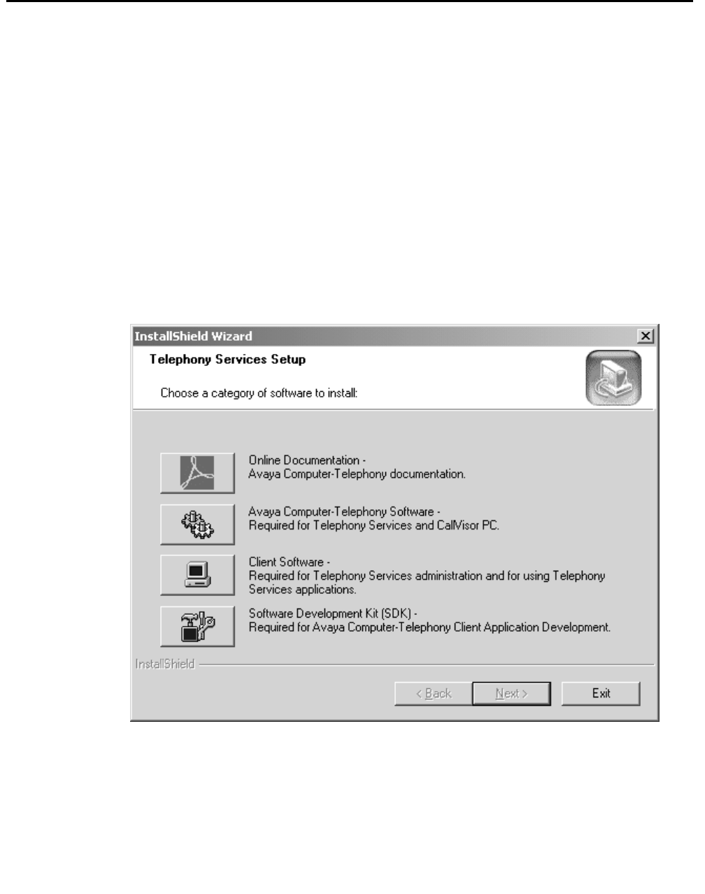
Installing the Windows Client Software
Issue 1 October 2003 101
Installing the Windows Client Software
Follow these steps for an initial installation of Telephony Services software on the Windows
client workstation designated as the Administrative Client Workstation. You can click
Cancel or Exit at any time to exit from the Setup program.
1. Log on to the PC as a user with administrator-equivalent permissions.
2. Insert the CD into the CD-ROM drive.
(When Windows NT, Windows 2000, Windows XP is using the Explorer shell, the
Setup program runs automatically if you have not disabled the AutoRun feature).
3. (Applies only if AutoRun is disabled) Click Start, then click Run. In the Run dialog box,
enter D:\WININST\SETUP.EXE (or Browse to it on the CD) to start the Setup
program.
The Telephony Services Setup screen displays:
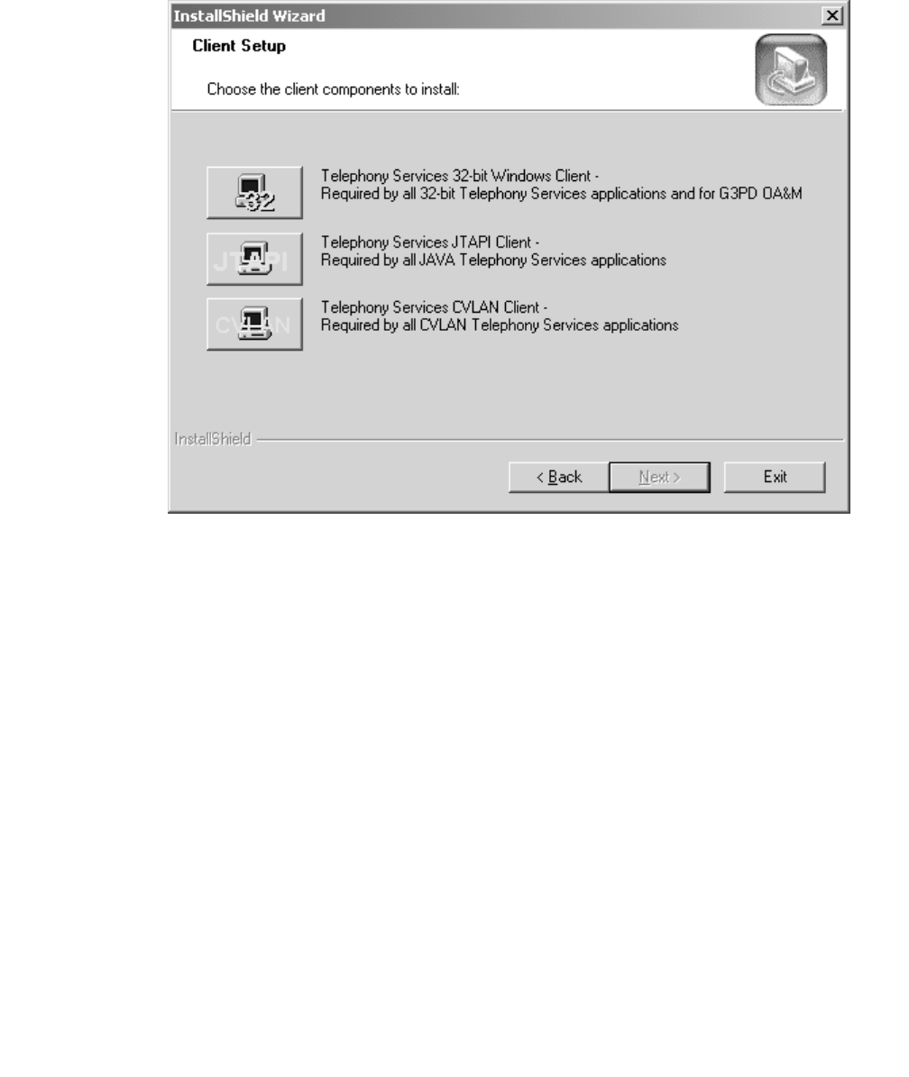
Installing Avaya Computer Telephony TSAPI Client Software
102 Installation Guide
4. Click on the Client Software button.
Setup displays the Client Setup dialog box.
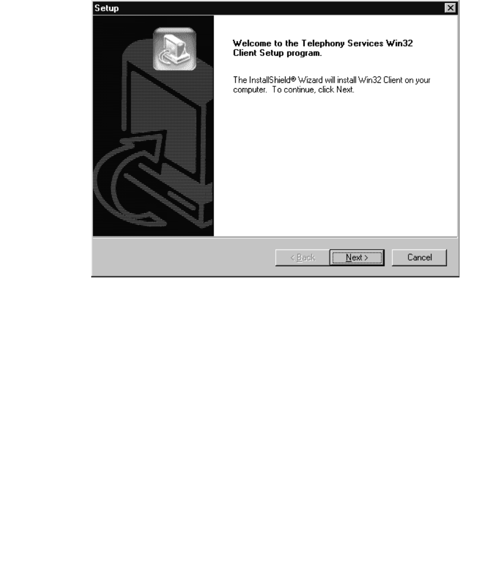
Installing the Windows Client Software
Issue 1 October 2003 103
5. Click the button for Telephony Services 32-bit Windows Client.
Setup displays the Welcome dialog box.
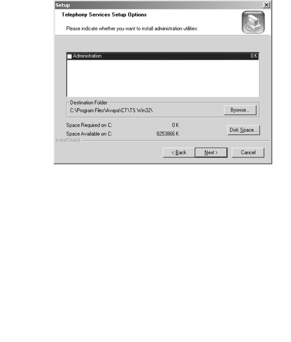
Installing Avaya Computer Telephony TSAPI Client Software
104 Installation Guide
6. Click Next to continue with the installation.
Setup displays the Telephony Services Setup Options dialog box.
T
7. If applicable, under Components, click the checkbox to select Administration Utilities,
and click Next.
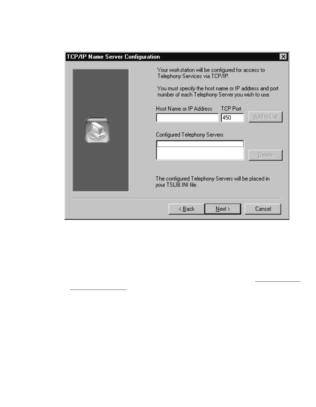
Installing the Windows Client Software
Issue 1 October 2003 105
Note:
Note: Select Administration Utilities only if you are responsible for administering
and maintaining the Avaya Computer Telephony Server.
Setup displays the TCP/IP Name Server Configuration dialog box.
8. (See the Note below for firewall installations.) In the Host Name or IP Address field
enter the IP address of the Telephony Server, and in the TCP Port field, enter 450. If
your installation uses more than one Telephony Server, click Add to List.
Note:
Note: If you are installing the client software in a firewall environment, see For
more information about NAT and Firewall environments, see Implementing
a Firewall Strategy on page 34.
9. (Skip this step if you used IP addresses in Step 8) In the Host Name or IP Address
follow these guidelines for your host name entry.
●If you are not using DNS, enter the host name of the Tserver.
●If you using DNS, type the fully qualified domain name, such as
tserver.company.com

Installing Avaya Computer Telephony TSAPI Client Software
106 Installation Guide
Note:
Note: If you enter the wrong Host Name or mistype the name, a warning message
displays stating that the name appears to be invalid. The name will be added
to the list but you should contact your administrator to verify that you have
entered the address correctly.
Note:
Note: Setup saves the information from the TCP/IP Name Server Configuration
dialog box in a tslib.ini file in the Windows directory. You can use a copy of
the tslib.ini file to streamline subsequent client installations. See Setting Up
Multiple Clients on page 108.
Setup searches your system for old Telephony Services software and issues a
message as it performs each search.
If the Setup program finds copies of CSTA32.DLL and ATTPRV32.DLL, it will
request confirmation to delete the old software.
Installing the Windows Client Software
Issue 1 October 2003 107
Note:
Note: It is recommended that you allow Setup to remove these files. (Setup does
not make copies.) If you do not remove these files, Telephony Services
applications may not operate correctly.
After completing the search, Setup copies the appropriate files and creates the TS
Win32 Client program group (Windows NT 3.51) or program folder in the “Start”
menu (Windows 95, Windows 98, Windows NT, Windows 2000 or Windows XP).
10. Click Finish.
This completes the Telephony Services 32-bit Windows client installation and setup.

Installing Avaya Computer Telephony TSAPI Client Software
108 Installation Guide
Installing the Windows Client Software from a Network Drive
This section describes how to install Windows 32-bit client software from a network drive.
In addition, it includes information on how to verify the installation. You can use this
procedure to set up additional administrative clients or multiple basic clients (basic clients
are client workstations without the administrative software).
To install the Windows client software from a network drive, you must first transfer the
WIN32 directory from the CD to the network drive. Then you can install from the file server.
1. Create or locate the directory \CSTA\CLIENT\TSAPI\Windows on a network drive.
2. Change to the \CLIENT\TSAPI\Windows directory on the CD-ROM.
3. Copy all files from the \CLIENT\TSAPI\Windows directory on the CD-ROM to the
\CSTA\CLIENT\TSAPI\WIN32 directory on the network drive. Use the Windows File
Manager, the Windows Explorer, or the following DOS command:
XCOPY source_directory destination_directory /s /e
!CAUTION:
CAUTION: Do not use the COPY command for this procedure. It is important to
maintain the directory structure within each subdirectory.
Note:
Note: Use an ASCII text editor such as Windows Notepad to read the
README.TXT file (located in \CLIENT\TSAPI\Windows\README.TXT).
This file contains information you may need before installing Telephony
Services on your client.
4. From the \CSTA\CLIENT\TSAPI\Windows directory on the network drive, run
SETUP.EXE.
Setting Up Multiple Clients
If multiple clients are to use the same Telephony Server, you can simplify subsequent client
installations. You must install from a network drive to perform this procedure.
●Install the Telephony Services Client on a client workstation. Then, do either of the
following:
●Copy the tslib.ini file that you created on the client (located in the Windows directory)
back to the Windows directory on the network file server. Any subsequent installations
will then have the new tslib.ini provided as the default, and each client will not have to
enter TCP/IP information.
●Or, copy the tslib.ini file that you created on the client (located in the Windows directory)
to a file server. This file must be accessible to all the TCP/IP Telephony Services clients.
Then, using a text editor, modify the tslib.ini file on the client and put the following line in

Installing the Windows Client Software
Issue 1 October 2003 109
the [Shared Admin] section: tslib.ini=n:\csta\tslib.ini (where "n:\csta\"
specifies the network drive and path to the tslib.ini file on your server). Remove the
[Telephony Servers] section. Copy the tslib.ini file from your client back to the Windows
directory on the network file server for use in subsequent installations.
Verifying 32-bit Client Software Installation
1. Run the "TS Test" (TSTEST.EXE) application. Click Start, point to Programs, Avaya
Computer Telephony, TS Win32 Client, and click TS Test.
2. Select the Tserver CSTA service you want to test by using the "Server" field.
3. Enter login information.
4. Enter the phone numbers that are properly administered in DEFINITY and the Avaya
Computer Telephony server in the "From" and "To" fields and select "Dial."
5. If you experience trouble, run "TS Spy" (TSSPY32.EXE), reexecute steps 1 through 4
and monitor the activity between the Tserver and TS Test.

Installing Avaya Computer Telephony TSAPI Client Software
110 Installation Guide
Installing TSAPI Solaris Sparc Client Software
The Solaris client software can be installed on a Solaris SPARC client workstation.
Note:
Note: In order to perform the installation, the Solaris Volume Manager must be
running. Solaris runs the Volume Manager by default; however, if the
Volume Manager has been shut off, the installation will fail.)
1. Become super-user (root): su
2. Enter the root password when prompted.
3. Insert the Telephony Services CD-ROM into your Solaris SPARC system CD-ROM
drive.
Note:
Note: Solaris File Manager users may find it more convenient to access the CD-
ROM by double-clicking on the tsapicl icon in the File Manager’s /cdrom
folder.
4. At the command prompt, enter the pkgadd command.
The pkgadd command format is as follows:
pkgadd -d /cdrom/cdrom0/client/TSAPI/sparc/tsapicl.spl
Note:
Note: For a detailed description of the pkgadd command, refer to your Solaris
SPARC documentation.
The system now displays a list of the packages.
5. Select the tsapicl package.
6. Once the installation is complete a message is displayed, "Installation of tsapicl was
successful."
7. Type eject to eject the CD from the CD-ROM drive.
After installation has completed, asaidll.lib, asaidll.dll, libcsta.sl, libattpriv.sl, readme.txt,
tslibrc, tstest, header files, and some utilities will have been installed.


Installing Avaya Computer Telephony TSAPI Client Software
112 Installation Guide
Installing UnixWare Client Software
The Telephony Services client software for UnixWare can be installed from a command
line, from a CD, or from diskettes.
Installing from Command Line
The Telephony Services software is installed from the command line via the UnixWare
pkgadd command. To do this, you must be logged on as root. Desktop users should open
a "Terminal" window.
Note:
Note: For a detailed description of the pkgadd command, refer to your UnixWare
documentation.
Installing from the CD
Follow these steps to install the UnixWare client from the CD.
1. Become super-user (root): su
2. Enter the root password when prompted.
3. Insert the Telephony Services CD-ROM into your workstation CD-ROM drive.
4. At the command prompt, mount the CD-ROM.
The mount command format is as follows:
mount -F cdfs -r /dev/cdrom/device /mountpoint
Note: For UnixWare 7.x, use this format
mount -F cdfs -r -onoextend /dev/cdrom/device /mountpoint
where device specifies the CD-ROM drive that contains the Telephony Services
installation disk and mountpoint is the name of an existing directory
(such as /cdrom1 or /CD-ROM_1) on which to mount the CD-ROM. You can use the
ls command to find the appropriate names for your system.
Note:
Note: Desktop users may find it easier to mount the CD-ROM by double-clicking
on the CD-ROM icon in the "Disks-etc" folder.

Installing UnixWare Client Software
Issue 1 October 2003 113
5. At the command prompt, enter the pkgadd command.
The pkgadd command format is as follows:
pkgadd -d /mountpoint/client/tsapi/unixware/nwtslib.spl
where mountpoint is the name of an existing directory (such as /cdrom1 or
/CD-ROM_1) on which to mount the CD-ROM. (Note that the full pathname, beginning
with a ’/’, is required.)
6. The system now displays a list of the packages in the spool file. Press <Enter> to
select the nwtslib package.
7. Specify the transport type.
UnixWare clients can use either IPX/SPX or TCP/IP as their network transport. The
system displays a list of transports and the following message:
Please specify a transport type for the Telephony Services
library. (To access Windows NT, Windows 2000 or Windows XP
Telephony Servers, you must select "tcp.")
spxIPX/SPX Protocol
tcpTCP/IP Protocol
Select a transport type [?,??]
Type "s" for IPX/SPX or "t" for TCP/IP; then press <Enter>.
Note:
Note: This release of Telephony Services for Windows NT, Windows 2000,
Windows XP only supports TCP/IP as a network protocol; you must select
TCP/IP even though both options appear on the screen.
8. The pg command displays the Telephony Services "readme" file, tslib.readme.
This file contains information about changes that were made after the manuals were
completed.
9. The installation is complete. Unmount the CD-ROM.
The umount command format is as follows:
umount /dev/cdrom/device
where device specifies the CD-ROM drive that contains the Telephony Services
installation disk. You may now remove the CD-ROM.
Note:
Note: If TCP/IP is selected for the transport type, a template file called /usr/lib/
tslibrc is created during installation. For more information, see Editing the
Template File -- tslibrc on page 118.

Installing Avaya Computer Telephony TSAPI Client Software
114 Installation Guide
Installing from Diskette
To install a UnixWare client using a diskette, you must first create the installation diskette,
then follow the installation procedure using the files on the diskette. You will need one
formatted high-density diskette.
1. Become super-user (root): su
Enter the root password when prompted.
2. Insert the Telephony Services CD-ROM into your workstation CD-ROM drive.
3. At the command prompt, mount the CD-ROM.
The mount command format is as follows:
mount -F cdfs -r /dev/cdrom/device /mountpoint
where device specifies the CD-ROM drive that contains the Telephony Services
installation disk and mountpoint is the name of an existing directory (such as /
cdrom1 or /CD-ROM_1) on which to mount the CD-ROM. You can use the ls
command to find the appropriate names for your system.
Note:
Note: Desktop users may find it easier to mount the CD-ROM by double-clicking
on the CD-ROM icon in the "Disks-etc" folder.
4. Change to the UnixWare client software directory.
cd /mountpoint/client/tsapi/unixware <Enter>
5. Insert an empty formatted diskette into the drive. Copy the package file using the
following command:
cat nwtslib.spl >/dev/fd0 <Enter>
6. Leave the unixware directory.
cd / <Enter>
7. Unmount the CD-ROM.
The umount command format is as follows:
umount /dev/cdrom/device
where device specifies the CD-ROM drive that contains the Telephony Services
installation disk. You may now remove the CD-ROM.
8. Remove the diskette from the drive. Attach a label to the diskette and write the
following information on it:

Installing UnixWare Client Software
Issue 1 October 2003 115
Telephony Services UnixWare Client <DISK1> Disk 1 of 1
9. From the client where you wish to install the software, enter the pkgadd command.
The pkgadd command format is as follows:
pkgadd -d diskette [n]
where n specifies the number of the disk drive containing the installation diskette.
Follow the procedure, "Installing from the CD," beginning with step 6.

Installing Avaya Computer Telephony TSAPI Client Software
116 Installation Guide
About Installing HP-UX Client Software
The Avaya Computer Telephony HP-UX client software is distributed on CD-ROM in tar
(tape archive) format. The Avaya Computer Telephony HP-UX client software comes in a
multi-threaded version (HP-UX 10).
Note:
Note: HP-UX clients require a CD-ROM drive. You can not install the HP-UX client
from floppy disks or from a network drive.
There are two methods for installing the software.
●Log in to the computer as root, and install the HP-UX client software from the command
line using the swinstall command.
●As an alternative to logging in as root, Use the HP System Administration Manager
(SAM) to perform the installation.
For more information about the swinstall command or SAM, refer to your HP-UX
documentation.
Installing HP-UX Client Software
Follow this procedure to install HP-UX Client Software.
1. From the computer where you are installing the HP-UX client software,
type su - root to log in as root.
The system prompts you for the root password.
2. Type the root password.
3. Set and export the DISPLAY environment variable by typing the following command
sequence.
DISPLAY=:0.0
export DISPLAY
4. Insert the Avaya Computer Telephony CD-ROM into your computer’s CD-ROM drive.
5. Use the mount command to mount the CD-ROM drive. For example, type:
mount -F cdfs /dev/dsk/device/mountpoint
where device specifies the CD-ROM drive that contains the Telephony Services
installation disk and mountpoint is the name of an existing directory

Installing HP-UX Client Software
Issue 1 October 2003 117
(such as /cdrom1 or /CD-ROM_1) on which to mount the CD-ROM. You can use the
ls command to find the appropriate names for your system.
6. Use the swinstall command to start the software installation. From the command
line, type:
swinstall -s /mountpoint/CLIENT/TSAPI/HPUX/TSLIB.TAR\;1
The system displays the SD Install - Target Selection dialog box.
7. Follow a, b, and c to select installation targets.
a. From the Targets list, highlight the targets on which you want to install the software.
b. From the Actions menu, choose Mark for Install.
c. Again, from the Actions menu, choose Show Software For Selection.
The system displays the SD Install - Software Selection dialog box.
8. Select tslib.
9. From the Actions menu, choose Mark for Install.
10. Before continuing to Step 11, it is recommended that you follow these steps to review
the "Readme" file that accompanies the software.
a. Highlight Avaya Computer Telephony
b. Select Actions, Show Description of Software...., Readme
c. Review the Readme file.
11. Select Actions, and click Install (analysis)....
12. When the analysis is complete, click OK to proceed with the installation.
13. When the installation is complete, click Done to close the Install window.
14. Click File from the menu bar and then click Exit.
15. Remove the CD-ROM using the umount command.
The umount command format is as follows:
umount /dev/dsk/device
where:
device specifies the CD-ROM drive that contains the Avaya Computer Telephony
installation disk.
16. Remove the CD-ROM.
This completes the procedure to install the Avaya Computer Telephony HP-UX client
software. Keep in mind that you must edit the "tslibrc" file for each client. See the next
section, Editing the Template File -- tslibrc on page 118.

Installing Avaya Computer Telephony TSAPI Client Software
118 Installation Guide
Editing the Template File -- tslibrc
This information applies to HP-UX, Solaris, and UnixWare clients only.
If you select TCP for the transport type during client installation, Avaya Computer
Telephony creates a template file called /usr/lib/tslibrc.
The tslibrc file contains sample names and addresses and you must change the sample
addressing information to the actual addressing and port information for the server your
clients need to access. Follow these guidelines to edit the tslibrc file.
●If you are using IP addresses
- In a non-firewall environment, enter the IP address of the NIC for the Telephony
Server (as opposed to the NIC for the G3PD), followed by a space and 450, for
example: 122.222.000 450
- If you are setting up Avaya Computer Telephony in a firewall environment, see
Implementing a Firewall Strategy.
●If you are using a host name
- Enter a valid host name and 450, for example: telserver 450. The host name must
resolve to a routable IP address.

Removing Telephony Services Client Software
Issue 1 October 2003 119
Removing Telephony Services Client Software
This section contains procedures for removing Windows client software.
Removing Windows 32-Bit Client Software
Use the standard Windows removal procedure to uninstall the Windows 32-bit client
software.
1. From the desktop, click Start, point to Settings and click Control Panel.
2. From the Control Panel, click Add/Remove Programs.
3. Windows displays the Add/Remove Programs Properties dialog box.
4. Select Avaya Computer Telephony TS Win32 client, and click Add/Remove.
Note:
Note: You will not receive a confirmation message once you click on the Add/
Remove button.
The uninstall program removes the software and displays an Information box indicating
that the program and all of its components have been removed.
5. Click Finish.
This completes the procedure to remove a software program.
Removing TSAPI Solaris Client Software
Follow these steps to remove the TSAPI Solaris client software:
1. Use the pkgrm command.
2. The system displays a list of installed packages.
3. Enter the number or the name of the package you want to remove. In this case the
name of the package is:
tsapicl
4. Select "Yes" to remove the package.
The software is uninstalled.
5. Type "q" to quit the pkgrm command.

Installing Avaya Computer Telephony TSAPI Client Software
120 Installation Guide
Removing UnixWare Client Software
Follow these steps to remove the UnixWare client software:
1. Use the pkgrm command.
The system displays a list of installed packages.
2. Enter the number corresponding to the nwtslib package.
3. Select Yes to remove the package.
The software is uninstalled.
4. Type q to quit the pkgrm command.
Removing HP-UX Client Software
Follow this procedure to remove the HP-UX client software.
1. From the computer where you are removing the HP-UX client software, type su -
root to log in as root
2. Type swremove -i
3. Choose tslib from the list of packages to be removed.
This completes the procedure to remove the HP-UX client software.

Issue 1 October 2003 121
Chapter 5: Using CVLAN
This chapter includes the following sections which provide information about using CVLAN
(CallVisor PC Local Area Network) software in the Windows environment.
●Overview on page 122
●Implementing CVLAN and Telephony Services on page 123
●The CVLAN Server on page 125
●CVLAN Administration Guidelines for Sharing Links on page 126
●Before You Administer CVLAN Clients on page 127
●Basic CVLAN Client Administration on page 127
●Starting the CVLAN Server on page 132
●Stopping the CVLAN Server on page 135
●CVLAN Client Hardware and Software Requirements on page 136
●Installing CVLAN Client Software on page 138
●Removing CVLAN Client Software on page 146
●CVLAN Software Development Kit on page 147

Using CVLAN
122 Installation Guide
Overview
CVLAN is a client/server implementation of the Call Visor PC API. (CallVisor PC is a
proprietary Application Program Interface that supports the Adjunct/Switch Application
Interface -- ASAI).
CVLAN consists of a client component and a server component.
●The CVLAN server is installed on the Avaya Computer Telephony server (which must be
running Windows NT, Windows 2000 or Windows XP), and it provides LAN connectivity
to remote workstations that require access to CallVisor PC.
●The CVLAN client, which can be installed on the Avaya Computer Telephony server or a
client workstation, provides client PCs with remote access to the switch (by way of the
CVLAN server).
Avaya Computer Telephony provides CVLAN client packages for the following
platforms:
●UnixWare
●Solaris x86
●Solaris Sparc
●IBM Advanced Interactive Executive (AIX)
●Windows

Implementing CVLAN and Telephony Services
Issue 1 October 2003 123
Implementing CVLAN and Telephony Services
Avaya Computer Telephony is an integrated software offer that includes two servers,
Telephony Services Server (Tserver) and the CVLAN Server. By bundling the two software
components, Avaya Computer Telephony enables you to effect an integrated installation of
both applications. Keep these points in mind if you are implementing both applications.
●Up to eight CTI logical links can be shared between Telephony Services and CVLAN
applications.
●Telephony Services and CVLAN rely on a common user interface, the G3 PBX DRIVER
configuration utility, to administer links.
●Telephony Services and CVLAN applications can operate simultaneously on the same
Windows-based server (Windows NT, Windows 2000 or Windows XP).
●CVLAN does not rely on the Telephony Services security database for client
authentication. Instead, it authenticates clients based on the client IP address or the
host name. See ‘‘Basic CVLAN Client Administration’’ on page -127.
Figure 5-1 depicts a coresident implementation of Telephony Services and CVLAN.
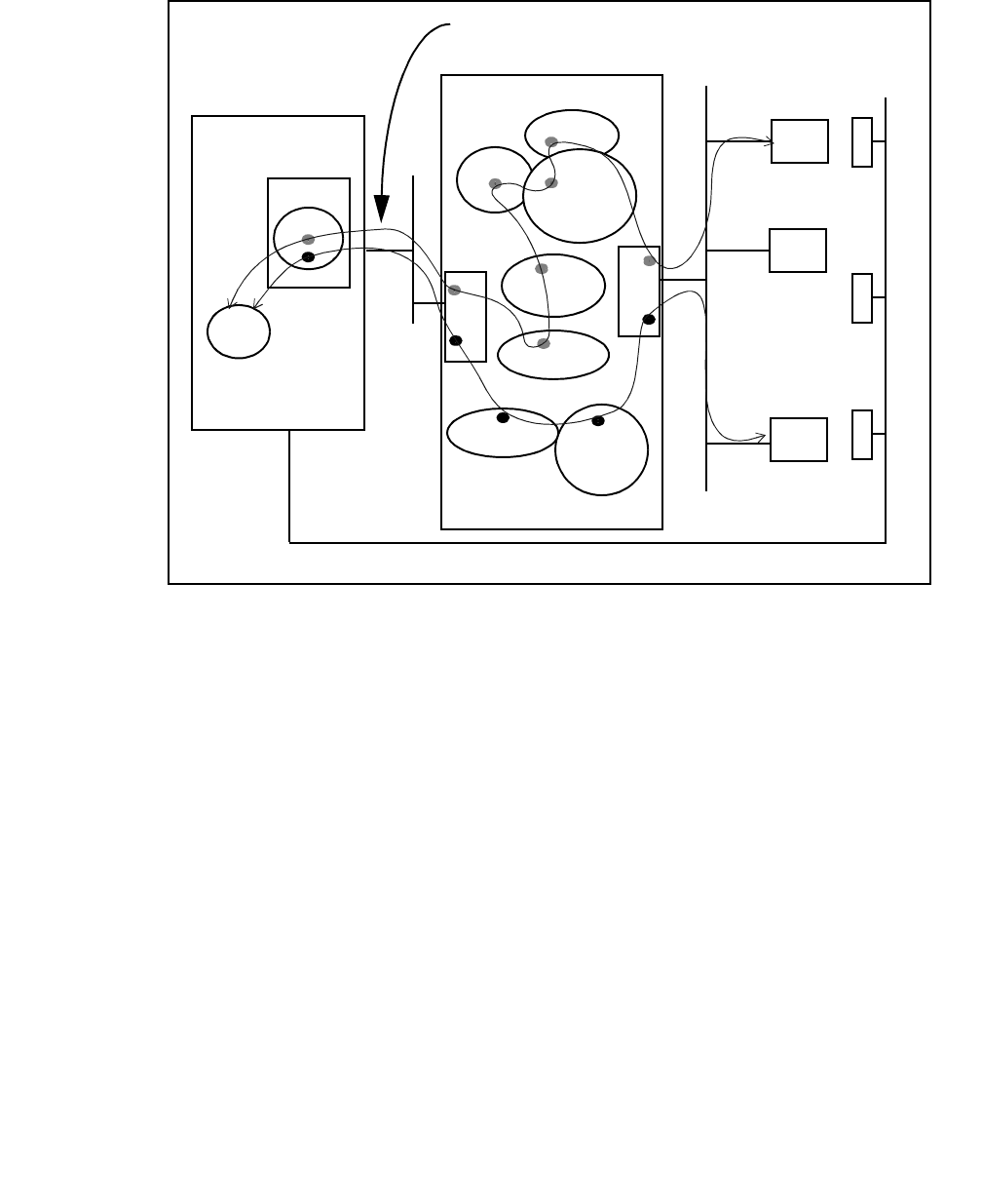
Using CVLAN
124 Installation Guide
Figure 5-1: CVLAN and Telephony Services — Coresidency at a Glance
ASAI.DLL
TSLIB
SDB
DEFINITY ECS
Avaya CT Server
TSAPI
Client
Tserver
Phone
Phone Line
NIC
NIC
G3PD
CVLANCLI.DLL
DLG
MAPD
JTAPI
Client
CVLAN
Client
ASAI
Up to 8 logical links can be shared by CVLAN and
Telephony Services
CVLAN
Server
Phone Phone
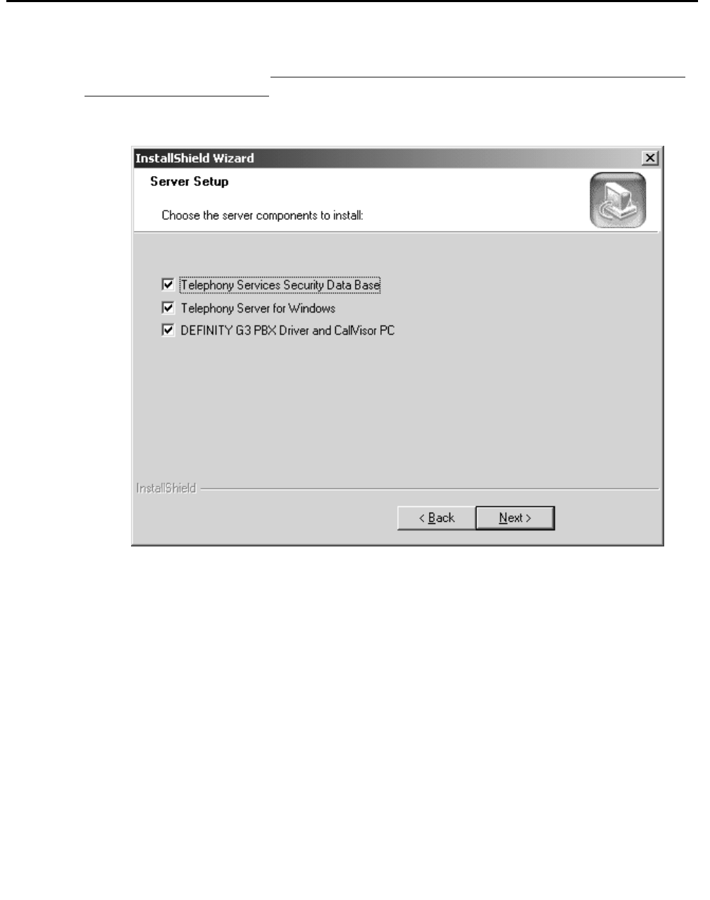
The CVLAN Server
Issue 1 October 2003 125
The CVLAN Server
If you follow the procedure Procedure for Initial, Default Installation of Avaya Computer
Telephony Server Software on page 70 , the CVLAN server is installed when the checkbox
for "DEFINITY G3PBX Driver and CVLAN" is selected (it is selected by default).

Using CVLAN
126 Installation Guide
CVLAN Administration Guidelines for Sharing Links
Keep the following information in mind if your CTI implementation supports both CVLAN
and Tserver (Telephony Services Server) applications.
●Link sharing. CVLAN server and Telephony Services applications running concurrently
can access switch CTI functionality via the same Tserver-to-Switch links.
●Routing requests. Tserver-to-Switch links are not sharable by CVLAN server and
Telephony Services applications for receiving routing requests from the switch. That is,
a CVLAN server application that handles route requests from the switch should not use
a link that is shared with a Telephony Services application that also expects to receive
its own routing requests.
●Load balancing. Consideration of load balancing by CVLAN server applications may
be required for optimal link usage when CVLAN server and Telephony Services
applications share Tserver-to-Switch links.
●Link versions. The first application to access a link will set that link’s version level.
Other applications that may share the link will not be able to negotiate a different link
version. This may cause an application that requires particular link versions to fail to run
because no available links offer an acceptable version. Avoid this problem by ensuring
that the applications do not share a link.
For additional information about link sharing, handling routing requests, adjunct routing,
load balancing, and checking link versions, see Chapter 2 of Avaya Computer Telephony
CVLAN Programmer’s Reference (CALLVISR.PDF).

Before You Administer CVLAN Clients
Issue 1 October 2003 127
Before You Administer CVLAN Clients
Before you administer CVLAN take the following precautions:
●Make sure that the G3PD is not loaded.
Refer to "Loading and Unloading PBX Drivers" (describes how you can load or unload
the dynamic link libraries (DLLs) for the Tserver) in Chapter 8 of Avaya Computer
Telephony, Telephony Services Administration and Maintenance (NETMANGD.PDF on
the Avaya Computer Telephony CD ROM).
●Make sure the CVLAN service is stopped — See ‘‘Stopping CVLAN with the Telephony
Services Controller’’ on page -135.
Basic CVLAN Client Administration
Use this section to familiarize yourself with a few basic tasks associated with administering
CVLAN clients.
●adding a client
●editing a client
●removing a client
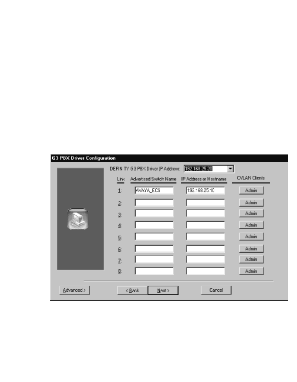
Using CVLAN
128 Installation Guide
Adding a CVLAN Client
When you establish a link for communications between the Avaya Computer Telephony
server and the switch you establish a communications path for CVLAN clients (links are
shared between the CVLAN server and the Tserver).
Follow this procedure for adding a CVLAN client.
1. Click Start, point to Programs, Avaya Computer Telephony, DEFINITY G3 PBX
Driver, and click on G3 PBX Driver Configuration.
Note:
Note: If the G3PD or CVLAN client is running, the system displays a Warning box,
with the following message, "Either the DEFINITY G3 PBX Driver or a
CVLAN Client is running. Changes made to the configuration will not take
effect until the next time the DEFINITY G3 PBX Driver is loaded. If you
receive this warning message, click OK.
The system displays the G3PX Driver Configuration dialog box.
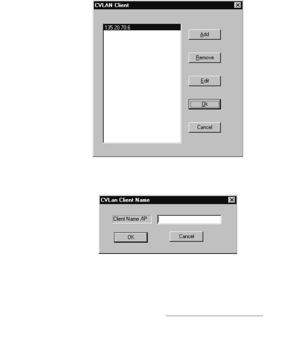
Basic CVLAN Client Administration
Issue 1 October 2003 129
2. For each link click Admin to add a CVLAN client.
The system displays the CVLAN client dialog box.
3. Click Add to add a client.
The system displays the CVLAN Client name dialog box.
4. Enter the IP address of your CVLAN client, based your configuration requirements and
click OK.
Note:
Note: You must enter an IP address in this dialog box. Client names (also referred
to as Host Names) are not permitted.
For guidelines about IP addresses, see Implementing a Firewall Strategy on page 34.
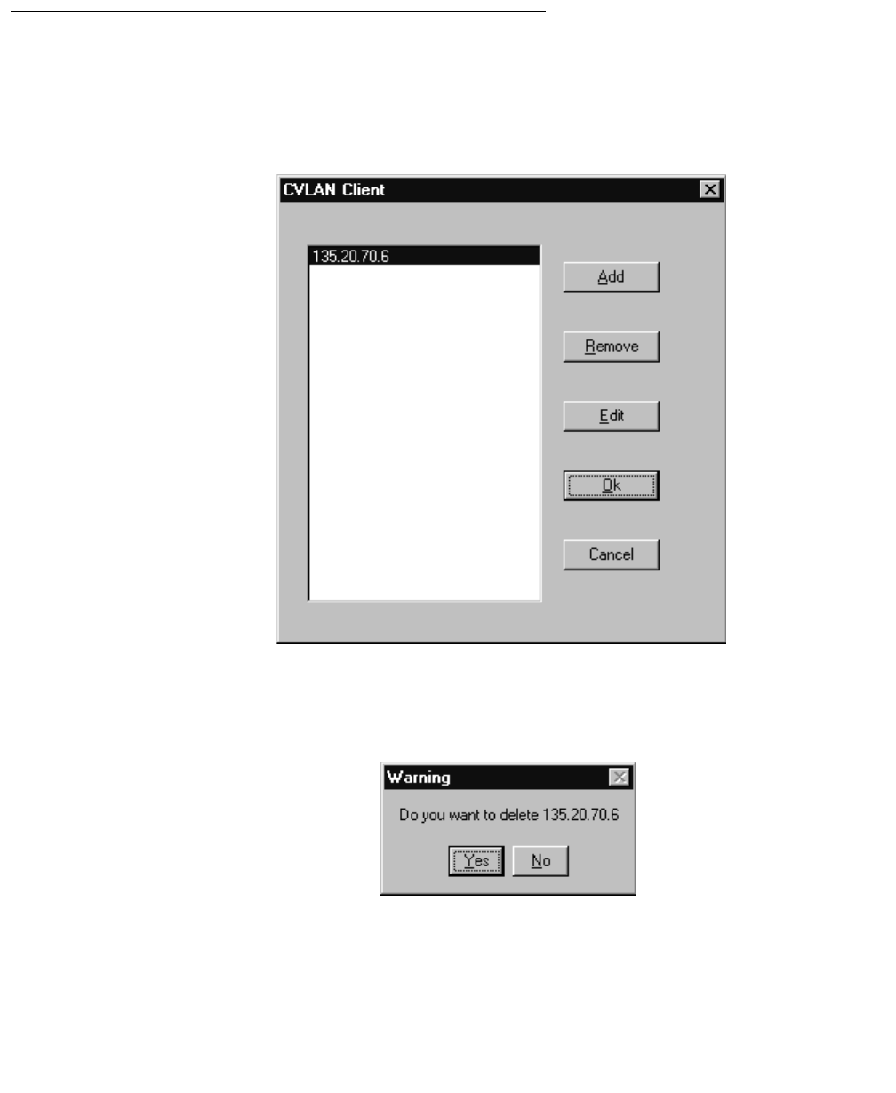
Using CVLAN
130 Installation Guide
This completes the procedure to add a client.
Removing a CVLAN Client
1. Follow Steps 1 through 5 of the procedure for Adding a CVLAN Client.
The system displays the CVLAN client dialog box.
2. Enter a new client name or IP address and click Remove.
The system displays the Warning dialog box.
3. Verify that this is IP address of the client you want to delete, and click Yes.
4. This completes the procedure to remove a client.
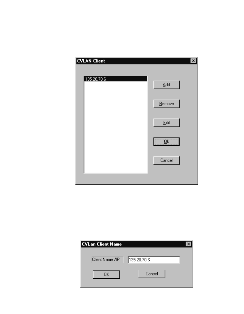
Basic CVLAN Client Administration
Issue 1 October 2003 131
Editing a Client
1. Follow Steps 1 through 5 of the procedure for Adding a CVLAN Client.
The system displays the CVLAN client dialog box.
2. Enter the IP address of the CVLAN Client and click Edit
Note:
Note: Recall from the Note on page -129 that CVLAN clients are specified by IP
addresses only.
The system displays the CVLAN Client Name dialog box.

Using CVLAN
132 Installation Guide
3. Select the current IP address (135.20.70.6), and overwrite it with the IP address you
want to use. Click OK.
The system displays the Warning dialog box (overwriting deletes the previous client).
4. Verify that this IP address of the client that you want to edit and click Yes.
This completes the procedure to edit (and remove) a client.
Starting the CVLAN Server
This section describes the following methods for starting the CVLAN server:
●Starting CVLAN with the Telephony Services Controller — this procedure starts both the
Telephony Services server (Tserver) and the CVLAN server. This is the recommended
method.
●Starting CVLAN from the Windows operating system — this procedure starts the
CVLAN server only. Use this method to start the CVLAN server independently of the
Tserver.
Starting the CVLAN Server with the
Telephony Services Controller
Follow these steps to start the CVLAN server from the Telephony Services controller (this
procedure starts both the Tserver and the CVLAN server).
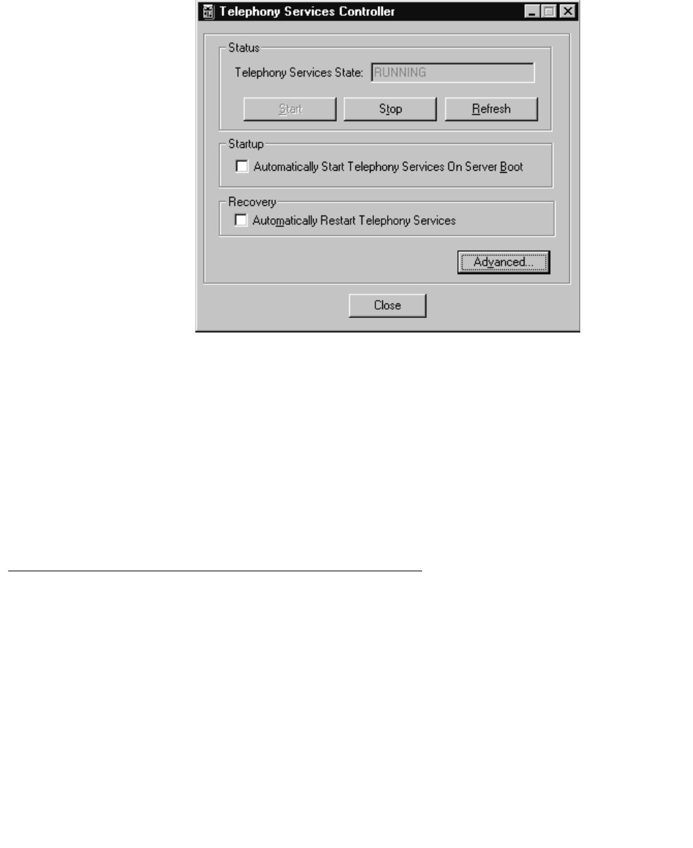
Starting the CVLAN Server
Issue 1 October 2003 133
1. Click Start, point to Programs, Avaya Computer Telephony, and click TS Controller.
2. Click Start to start Telephony Services.
Telephony Services starts the Tserver and the CVLAN.
3. Click OK to dismiss the information box and return to the "Telephony Services
Controller" dialog box.
On the Telephony Services controller dialog box, under "Status," the Telephony
Services state is listed as "RUNNING."
4. Click Close to exit the Telephony Services Controller dialog box.
This completes the procedure to manually start Telephony Services software.
Starting the CVLAN Server from the Windows Operating
System
Use this method to restart the CVLAN server independently of the Tserver.
1. Follow a or b depending on your Windows operating system.
a. Windows NT — Click Start, point to Settings, then click
Control Panel. Double-click Services.
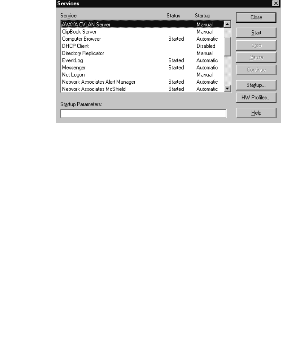
Using CVLAN
134 Installation Guide
b. Windows 2000 and Windows XP — Click Start, point to Settings, then click
Control Panel. Double-click Administrative Tools, and then double-click
Services.
The system displays the Services dialog box.
2. From the Service list box, select AVAYA CVLAN Server and click Startup.
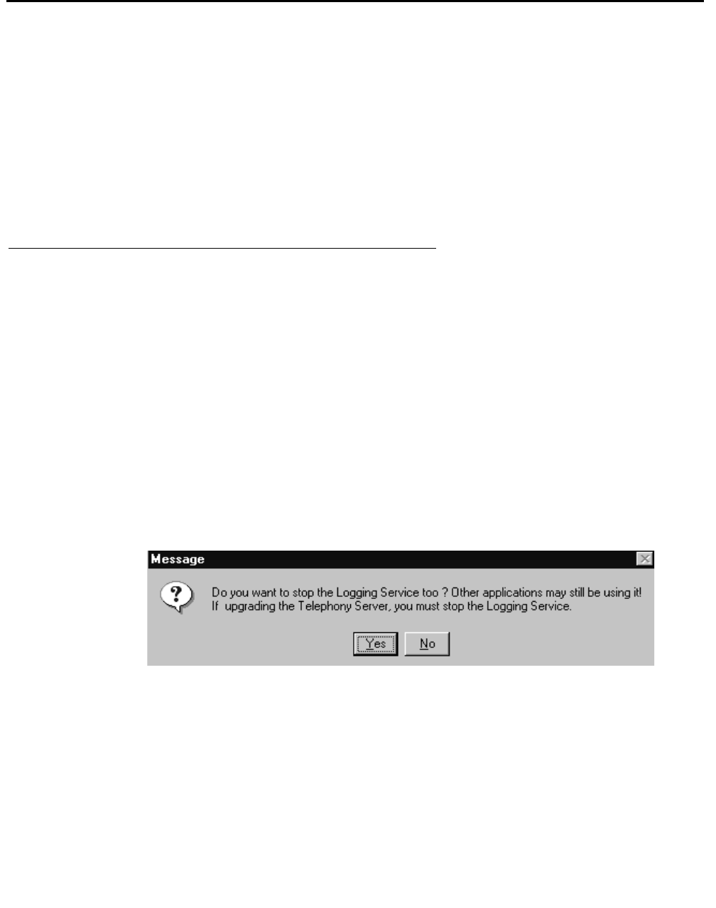
Stopping the CVLAN Server
Issue 1 October 2003 135
Stopping the CVLAN Server
This section describes the following methods for stopping the CVLAN server:
●Stopping the CVLAN server with the Telephony Services Controller— this procedure
stops both the Telephony Services server (Tserver) and the CVLAN server. This is the
recommended method.
●Stopping the CVLAN server from the Windows operating system — this procedure stops
the CVLAN server only. Use this method if your Tserver is running and the CVLAN
server does not seem to be operating.
Stopping CVLAN with the Telephony Services Controller
Follow this procedure to stop Telephony Services and the CVLAN server.
1. Click Start, point to Programs, Avaya Computer Telephony, and click TS Controller.
2. From the Telephony Services Controller dialog box, click Stop.
3. Select "Stop".
The Telephony Services and CVLAN server are stopped, and an Information box
displays.
4. Click OK
The operating system displays a message box that prompts you to stop the Logging
Service.
5. If you want to stop the Logging Service, Click Yes; otherwise, click No.
6. From the Telephony Services Controller dialog box, click Close to exit the Telephony
Services Controller.

Using CVLAN
136 Installation Guide
Stopping the CVLAN Service from the Windows Operating
System
Use this method if your Telephony Server (Tserver) is running and the CVLAN server does
not seem to be operating.
Follow this procedure to stop the CVLAN server from the Windows operating system.
1. Follow a or b, depending on your Windows operating system.
a. Windows NT — Click Start, point to Settings, then click Control Panel. Double-
click Services.
b. Windows 2000 and Windows XP — Click Start, point to Settings, then click
Control Panel. Double-click Administrative Tools, and then double-click
Services.
2. From the Services dialog, select CVLAN Server and Click Stop.
CVLAN Client Hardware and Software
Requirements
As a general guideline, if the operating system will load and run on an approved hardware
platform, CVLAN client software will also. Our suggestion is to first choose a software
platform and work with the Hardware Certification list provided with the Operating System.
CVLAN Client Software
CVLAN client software allows CallVisor PC applications to communicate with DEFINITY by
way of the CVLAN Server.

CVLAN Client Hardware and Software Requirements
Issue 1 October 2003 137
CVLAN Client Platforms
The CallVisor PC Local Area Network (CVLAN) client software can be installed on the
following client platforms:
Table 5-1: CVLAN Client Application Platforms
Client Platform Operating System Server Version
Windows Windows NT 4.0 or
Windows 2000 CVLAN 8.2
UnixWare SCO UnixWare 2.1.3 CVLAN 8.2
SCO UnixWare 2.1.2 (with
UnixWare patch 32801)
UnixWare 7
Solaris
SPARC™ Solaris SPARC 2.4, 2.5,
2.5.1,and 2.6 CVLAN 8.2
Solaris™ x86 Solaris x86 2.4, 2.5, and
2.51 CVLAN 8.2
IBM® AIX AIX 4.3 or 5.1 CVLAN 8.2
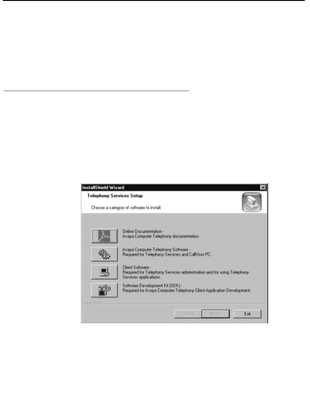
Using CVLAN
138 Installation Guide
Installing CVLAN Client Software
This section contains instructions for installing CVLAN client software on Windows NT,
Windows 2000, Solaris SPARC, Solaris x86, and UnixWare client workstations.
Note:
Note: See Table 5-1 on page -137 in for the list of supported CVLAN client
platforms.
Installing Windows Client Software
The CVLAN client software can be installed on a Windows NT or Windows 2000 client
workstation.
1. Insert the Avaya Computer Telephony CD into the CD-ROM drive (the Setup program
runs automatically if you have not disabled the AutoRun feature).
Setup displays the Telephony Services Setup dialog box.
2. Click the Client Software button.
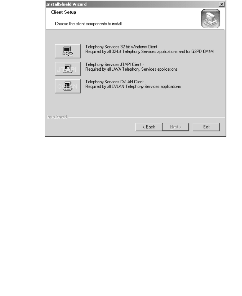
Installing CVLAN Client Software
Issue 1 October 2003 139
Setup displays the Client Setup dialog box
3. Click the CVLAN button.
Using CVLAN
140 Installation Guide
Setup displays the Setup Status Screen
4. When you CVLAN Setup has finished executing, you will be asked if you want to view
the Readme file now. Click Yes or No.
5. This installation is now complete.
Once you have completed the CVLAN installation, refer to the Avaya Computer Telephony
CVLAN Programmer’s Reference (CALLVISR.PDF) for more information, as follows.
●The utilities (itt, asai_test, and perf) are described in Chapter 10.
●Instructions for developing CVLAN applications are provided in Chapter 6.

Installing CVLAN Client Software
Issue 1 October 2003 141
Verifying Windows Client Software Installation
1. At the MS-DOS prompt, run "asai_test -m <server> <link number>" where <server> is
the name or IP address of the CVLAN server and
<link number> is the number of the link on that server.
2. It should respond with a "successful" message.
If it fails, check the TCP connectivity with ping, and the server link status by using the
DEFINITY G3PD Administrator utility.
For details on using the Link Status command, see the "Link Status Command" section
in Chapter 3 of Avaya Computer Telephony G3 PBX Driver and CVLAN Administration
and Maintenance (DEFNETM.PDF).
Installing Solaris SPARC Client Software
The CVLAN client software can be installed on a Solaris SPARC client workstation.
Note:
Note: In order to perform the installation, the Solaris Volume Manager must be
running. Solaris runs the Volume Manager by default; however, if the
Volume Manager has been shut off, the installation will fail.)
1. Become super-user (root): su
2. Enter the root password when prompted.
3. Insert the Telephony Services CD-ROM into your Solaris SPARC system CD-ROM
drive.
Note:
Note: Solaris File Manager users may find it more convenient to access the CD-
ROM by double-clicking on the cvlanxcl icon in the File Manager’s /
cdrom folder.
4. At the command prompt, enter the pkgadd command.
The pkgadd command format is as follows:
pkgadd -d /cdrom/cdrom0/client/cvlan/sparc/cvlanxcl.spl
Note:
Note: For a detailed description of the pkgadd command, refer to your Solaris
SPARC documentation.
The system now displays a list of the packages.

Using CVLAN
142 Installation Guide
5. Select the cvlanxcl package.
6. Type eject to eject the CD from the CD-ROM drive.
After installation has completed, asaidll.lib, asaidll.dll, header files, and some utilities
will have been installed.
Once you have completed the CVLAN installation, refer to the Avaya Computer Telephony
CVLAN Programmer’s Reference (CALLVISR.PDF) for more information, as follows.
●The utilities (itt, asai_test, and perf) are described in Chapter 10.
●Instructions for developing CVLAN applications are provided in Chapter 6.
Verifying Solaris SPARC
Client Software Installation
1. At the command prompt, run "asai_test -m <server> <link number>" where <server> is
the name or IP address of the CVLAN server and
<link number> is the number of the link on that server.
2. It should respond with a "successful" message.
If it fails, check the TCP connectivity with ping, and the server link status by using the
DEFINITY G3PD Administrator utility.
For information about using the Link Status command, see "Link Status Command" in
Chapter 3 of Avaya Computer Telephony G3 PBX Driver and CVLAN Administration
and Maintenance (DEFNETM.PDF).
Installing Solaris x86 Client Software
The CVLAN client software can be installed on a Solaris x86 client workstation.
Note:
Note: In order to perform the installation, the Solaris Volume Manager must be
running. Solaris runs the Volume Manager by default; however, if the
Volume Manager has been shut off, the installation will fail.)
1. Become super-user (root): su
2. Enter the root password when prompted.
3. Insert the Telephony Services CD-ROM into your Solaris x86 system CD-ROM drive.

Installing CVLAN Client Software
Issue 1 October 2003 143
Note:
Note: Solaris File Manager users may find it more convenient to access the CD-
ROM by double-clicking on the cvlanxl icon in the File Manager’s /cdrom
folder.
4. At the command prompt, enter the pkgadd command.
The pkgadd command format is as follows:
pkgadd -d /cdrom/cdrom0/client/cvlan/solx86/cvlanxcl.spl
Note:
Note: For a detailed description of the pkgadd command, refer to your Solaris x86
documentation.
The system now displays a list of the packages.
5. Select the cvlanxcl package.
6. Type q to quit the pkgadd command.
The installation is complete.
7. Type eject to eject the CD-ROM from the CD-ROM drive.
After installation has been completed, asaidll.lib, header files and some utilities will
have been installed.
Once you have completed the CVLAN installation, refer to the Avaya Computer Telephony
CVLAN Programmer’s Reference (CALLVISR.PDF) for more information, as follows:
●The utilities (itt, asai_test and perf) are described in Chapter 10
●Instructions for developing CVLAN applications are provided in Chapter 6
Verifying Solaris x86 Client Software Installation
1. At the command prompt, run "asai_test -m <server><link number>" where <server> is
the name or IP address of the CVLAN server and <link number> is the number of the
link on that server.
2. It should respond with a "successful" message.
If it fails, check the TCP connectivity with ping, and the server link status by using the
DEFINITY G3PD Administrator utility.
For information about using the Link Status command, see "Link Status Command" in
chapter 3 of the Avaya Computer Telephony G3 PBX Driver and CVLAN
Administration and Maintenance (DEFNETM.PDF).

Using CVLAN
144 Installation Guide
Installing AIX CVLAN Client Software
The CVLAN client software can be installed on an AIX client workstation.
1. At the command prompt, enter su to have the system grant you super-user status. The
system prompts you for the root password.
2. Enter the root password.
3. Insert the Avaya Computer Telephony CD-ROM into your AIX system CD-ROM drive.
4. Mount the CD-ROM.
5. At the command prompt, use the installp command to install the software (see
Command Syntax).
Command Syntax
installp -ca -d /mntdir/client/cvlan/aix/cvlan_~1.bff cvlan_client
Substitute mntdir with the directory where you mounted the CD-ROM.
6. The system will perform the installation.
Installing UnixWare Client Software
The CVLAN client software for the UnixWare client workstation can be installed from the
command line or from the CD.
Installing from the Command Line
The CVLAN client software for the UnixWare client workstation is installed from the
command line via the UnixWare pkgadd command. To do this, you must be logged on as
root. Desktop users should open a "Terminal" window.
Note:
Note: For a detailed description of the pkgadd command, refer to your UnixWare
documentation.
Installing from the CD
1. Become super-user (root): su
2. Enter the root password when prompted.
3. Insert the Telephony Services CD-ROM into your UnixWare system CD-ROM drive.
4. At the command prompt, mount the CD-ROM.

Installing CVLAN Client Software
Issue 1 October 2003 145
The mount command format is as follows:
mount -F cdfs -r /dev/cdrom/device/mountpoint
where device specifies the CD-ROM drive that contains the Telephony Services
installation disk and mountpoint is the name of an existing directory
(such as /cdrom1 or /CD-ROM_1) on which to mount the CD-ROM. You can use the
ls command to find the appropriate names for your system.
Note:
Note: Desktop users may find it easier to mount the CD-ROM by double-clicking
on the CD-ROM icon in the "Disks-etc." folder.
5. At the command prompt, enter the pkgadd command.
The pkgadd command format is as follows:
pkgadd -d /mountpoint/client/cvlan/unixware/cvlanxcl.spl
where mountpoint is the name of an existing directory
(such as /cdrom1 or /CD-ROM_1) on which to mount the CD-ROM. (Note that the full
pathname, beginning with a ’/’, is required.)
6. The system now displays a list of the packages in the spool file. Press <Enter> to
select the cvlanxcl package.
7. Unmount the CD-ROM.
The umount command format is as follows:
umount /dev/cdrom/device
where device specifies the CD-ROM drive that contains the Telephony Services
installation disk. You may now remove the CD-ROM.
After installation has completed, asaidll.lib, asaidll.dll, header files, and some utilities
will have been installed.
Once you have completed the CVLAN installation, refer to the Avaya Computer Telephony
CVLAN Programmer’s Reference (CALLVISR.PDF) for more information, as follows.
●The utilities (itt, asai_test, and perf) are described in Chapter 10.
●Instructions for developing CVLAN applications are provided in Chapter 6.

Using CVLAN
146 Installation Guide
Verifying UnixWare Client Software Installation
1. At the command prompt, run "asai_test -m <server> <link number>" where <server> is
the name or IP address of the CVLAN server and
<link number> is the number of the link on that server.
2. It should respond with a "successful" message.
If it fails, check the TCP connectivity with ping, and the server link status by using the
DEFINITY G3PD Administrator utility.
For information about using the Link Status command, see "Link Status Command" in
Chapter 3 of Avaya Computer Telephony G3 PBX Driver and CVLAN Administration
and Maintenance (DEFNETM.PDF).
Removing CVLAN Client Software
This section contains instructions for removing CVLAN client software from Windows NT,
Windows 2000, Solaris SPARC and UnixWare client workstations.
Uninstalling Windows Client Software
Use the standard Windows removal procedure to uninstall the CVLAN client software.
1. From the desktop click Start, point to Settings and click Control Panel.
2. From the Control Panel, click Add/Remove Programs.
Windows displays the Add/Remove Programs Properties dialog box.
3. Select Avaya Computer Telephony CVLAN client, and click Add/Remove.
The uninstall program removes the software and displays an Information box indicating
that the program and all of its components have been removed.
4. Click Finish.
This completes the procedure to remove a software program from a Windows machine.

CVLAN Software Development Kit
Issue 1 October 2003 147
Removing Solaris SPARC Client Software
If you want to remove the CVLAN client software from the Solaris SPARC client
workstation:
1. Use the pkgrm command.
A list of installed packages is displayed.
2. Enter the number corresponding to the cvlanxcl package.
3. Select "Yes" to remove the package.
The software is uninstalled.
4. Type q to quit the pkgrm command.
Removing AIX Client Software
If you want to remove the AIX client software from the client workstation, type the
command:
installp -u cvlan_client
Removing UnixWare Client Software
If you want to remove the UnixWare client software from the client workstation, as root type
the command:
pkgrm cvlanxcl
CVLAN Software Development Kit
The CVLAN Software Development Kit (SDK) provides a software development
environment for developing CVLAN applications for the adjunct (see Figure 5-2). The
following documents, which are included on the Avaya Computer Telephony CD,
supplement the tools in the SDK.
●Avaya Computer Telephony CVLAN Programmer’s Reference (CALLVISR.pdf)
●Avaya MultiVantage CallVisor ASAI Technical Reference (Asaitech.pdf)
●Avaya MultiVantage CallVisor ASAI Protocol Reference (Asaiprot.pdf)
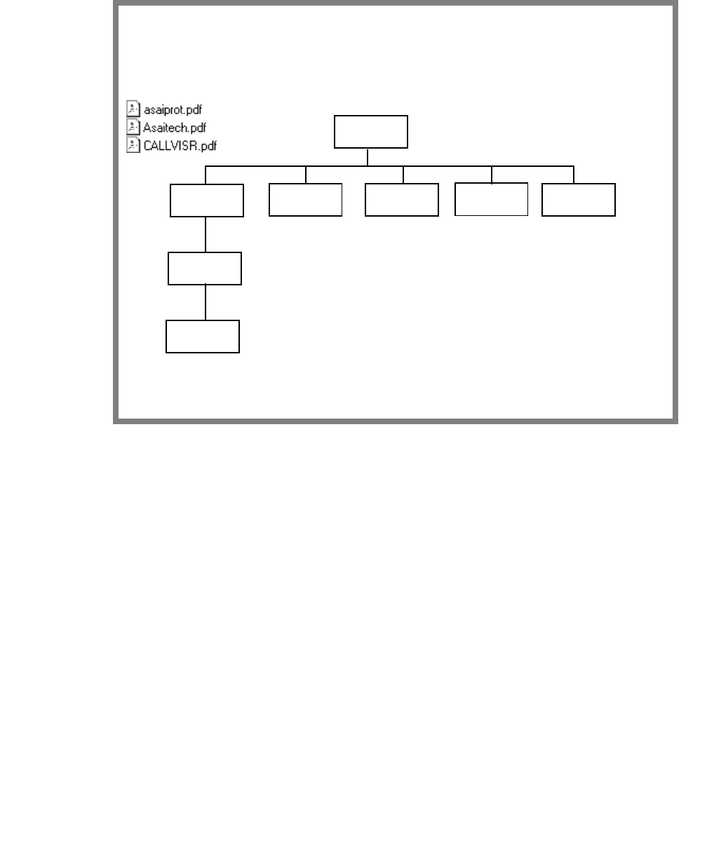
Using CVLAN
148 Installation Guide
Figure 5-2: CVLAN SDK at a Glance
CVLAN SDK Components
CVLAN
SAMPLE
INCLUDE
ASAI
Related
documents
ASAI
UTILS
SCRIPTS
INCLUDE

Issue 1 October 2003 149
Chapter 6: Installing JTAPI Client Software
This chapter contains the following sections that describe the installation procedure for the
JTAPI Client software.
●JTAPI Client Packaging on page 149
●Installing the JTAPI Client Software in the Windows Environment on page 151
●Manually Installing the JTAPI Client Software (Special Cases) on page 157
JTAPI Client Packaging
The JTAPI Client software is delivered as a collection of JAVA classes.
JTAPI comprises three software sets:
●SET 1, located in directory \client\Jtapi\OS_Independent, consists of the Avaya
implementation of the JTAPI specification.
●SET 2, located in directory \client\Jtapi\OS_Independent\all, consists of the Avaya
Computer Telephony implementation of JTAPI interfaces, bundled with Sun JTAPI 1.2
Early Access interfaces.
●SET 3, similar to SET 2 but also contains a special debug package located in
\client\Jtapi\OS_Independent\Debug.
Use the guidelines provided in each section to determine which set is appropriate for your
environment.
SET 1
Use this set of software only if Sun JTAPI interface classes are already in your client’s
CLASSPATH and you are concerned about download time from a web site:
●ECSJTAPI.ZIP — software in zip format for use by Netscape 3.x and other browsers, as
well as Java applications.

Installing JTAPI Client Software
150 Installation Guide
●ECSJTAPI.JAR — software in a signed jar format for use by Netscape 4.x and newer
browsers as well as Java applications.
●ECSJTAPI.CAB — software in a signed cab format for use by Internet Explorer 4.x
browsers.
The CLASSID is: {DDBB0340-3036-11d1-B2F7-006097B5344A}.
SET 2
This software set contains the Avaya JTAPI implementation bundled with the JTAPI
interfaces. Use this set of software if you do not already have the JTAPI interface classes
in your CLASSPATH:
●ECSJTAPIA.ZIP — software in zip format for use by Netscape 3.x and other browsers,
as well as Java applications.
●ECSJTAPIA.JAR — software in a signed jar format for use by Netscape 4.x and newer
browsers as well as Java applications.
●ECSJTAPIA.CAB — software in a signed cab format for use by Internet Explorer 4.x and
newer browsers.
The CLASSID is: {5DC537F1-39BE-11d1-B301-006097B5325A}.
SET 3
This software set also has the Avaya JTAPI implementation bundled with the JTAPI
interfaces. Additionally, it provides debugging capability. Use this set of software for
developing an application or applet. Do not use this software in production mode; but
instead use either Set 1 or 2.
●ECSJTAPID.ZIP — software in zip format for use by Netscape 3.x and other browsers.
●ECSJTAPID.JAR — software in a signed jar format for use by Netscape 4.x and newer
browsers as well as Java applications.
●ECSJTAPID.CAB — software in a signed cab format for use by Internet Explorer 4.x
browsers. The CLASSID for this is {278E9392-39B9-11d1-B301-006097B5325A}.
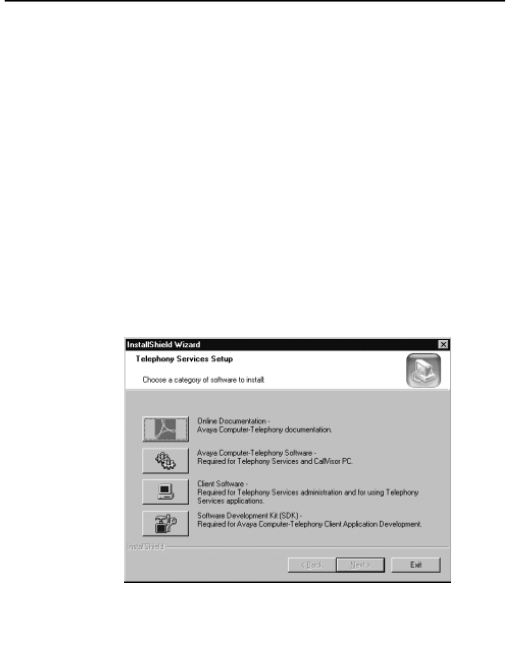
Installing the JTAPI Client Software in the Windows Environment
Issue 1 October 2003 151
Installing the JTAPI Client Software in the Windows
Environment
This section provides procedures for installing JTAPI Client software from the CD.
Note:
Note: The Windows installation will create Windows Start Menu shortcuts using
the Sun Microsystems Java Virtual Machine (JVM) if it is found. If Sun's
JVM is not found it will use the Microsoft JVM (If not found, it will default to
Sun’s in the shortcut). If you wish to utilize another JVM and use the
Windows Start Menu shortcuts for TSTest and ECSJtapiVersion you will
have to change the shortcut properties to invoke the desired JVM.
Note:
Note: The Windows installation will make an addition to your CLASSPATH system
variable. CLASSPATH will contain the necessary files and paths to utilize the
JTAPI client components. You may modify CLASSPATH to switch between
the different JTAPI packaging provided.
1. Insert the CD into the CD-ROM drive (the Setup program runs automatically if you
have not disabled the AutoRun feature).
Setup displays the Telephony Services Setup dialog box.

Installing JTAPI Client Software
152 Installation Guide
2. Click on the Client Software button.
Setup displays the Client Setup dialog box.
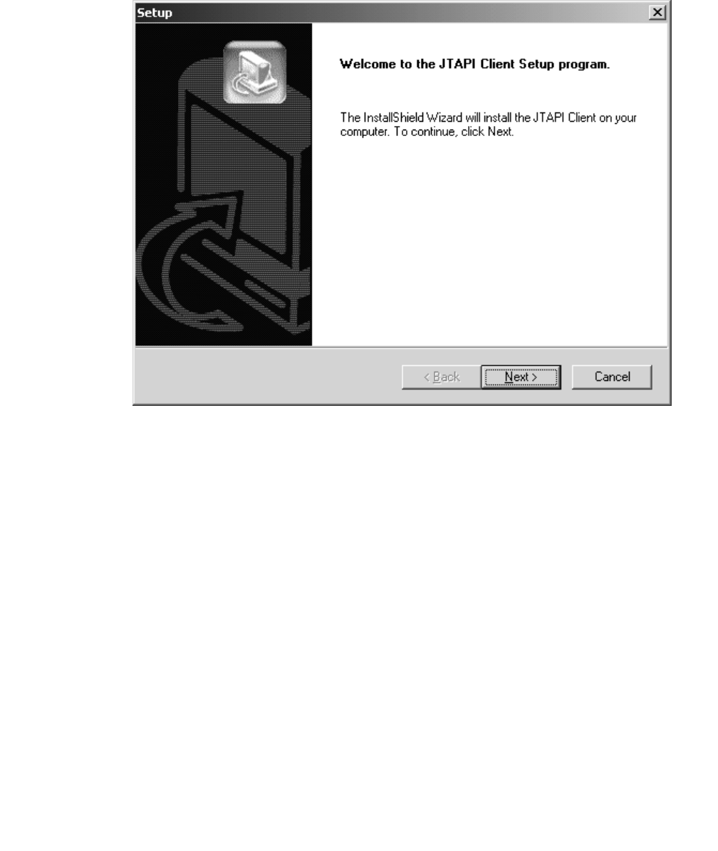
Installing the JTAPI Client Software in the Windows Environment
Issue 1 October 2003 153
3. Click on the Telephony Services JTAPI Client button.
Setup displays the Welcome Dialog for the Jtapi Client Install.
4. Click Next.
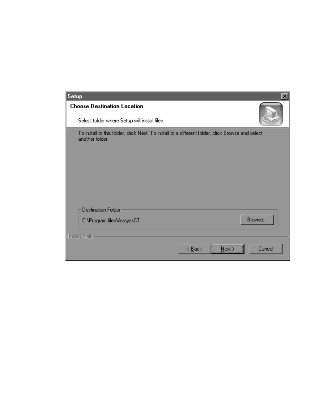
Installing JTAPI Client Software
154 Installation Guide
Note:
Note: At this time a search for previous versions/components is conducted so
processing may take a few minutes. If a previous version is found, a window
displays asking you if you would like to continue with the installation. Having
multiple versions installed is allowed and you may continue without
uninstalling. It is recommended that you uninstall the previous version to
avoid confusion. Uninstall directions are displayed.
If you continue with the installation procedure the Destination Location screen
displays.
5. You can accept the default destination folder or browse to select another destination
folder. Click Next to continue.
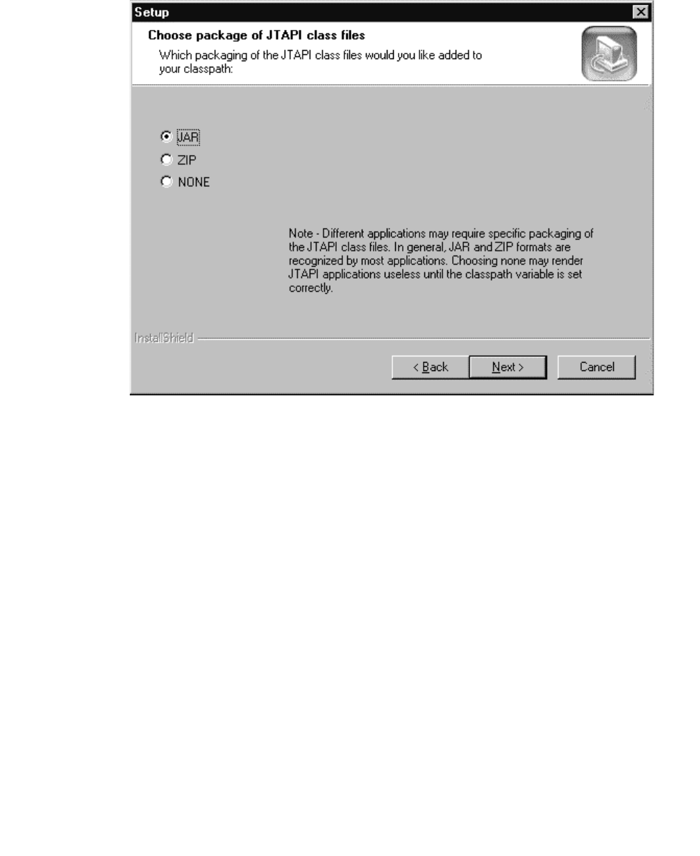
Installing the JTAPI Client Software in the Windows Environment
Issue 1 October 2003 155
Setup displays the JTAPI class files dialog box.
6. Select the appropriate packaging and click Next.
A message is displayed asking if the packaging selected should be added to the user’s
classpath. Select Yes or No.
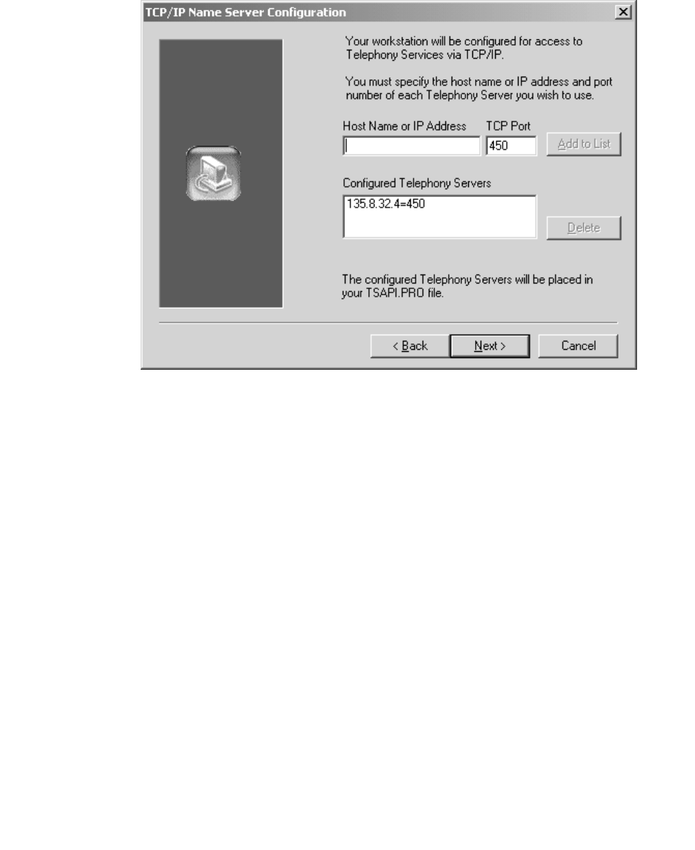
Installing JTAPI Client Software
156 Installation Guide
Setup displays the TCP/IP Server Configuration dialog box.
7. Enter the appropriate Host Name or IP Address of your Telephony Server (or Avaya
Computer Telephony Server) and click Next.
Once the appropriate files are copied, the installation is complete.
Test your JTAPI Client installation by making a call with the TSTest application from the
Avaya Computer Telephony JTAPI Client section of the Windows Start Menu.

Manually Installing the JTAPI Client Software (Special Cases)
Issue 1 October 2003 157
Manually Installing the
JTAPI Client Software (Special Cases)
For Non-Windows operating systems and some special cases on a Windows
Operating System a manual install may be necessary. Follow these directions as
applicable to the specific situation. The required files should be copied manually and
can be found on the Avaya Computer Telephony CD-ROM under this path:
\client\jtapi\os_independent\
Setup for Running JTAPI
Applets or Applications on a Client
You must have a Java Virtual Machine (VM) that supports Java Development Kit (JDK)
1.02 or later on your client.
1. Copy the software from SET 2 and TSAPI.PRO files to the same
directory<drive_letter>:<path>.
(For example, C:\JTAPI.)
2. Set the CLASSPATH to include <drive_letter>:<path> and the files from SET 2. (For
example, CLASSPATH=.;C:\JTAPI;C:\JTAPI\ECSJTAPIA.ZIP.) On a Windows NT,
Windows 2000 or Windows XP machine you can do this from the Control Panel,
System, Environment dialog.
3. Edit the TSAPI.PRO file to include the TCP/IP addresses or hostnames of the Tservers
that you will be using. The default port number is 450.
Setup for Running JTAPI Applets
in a Browser from a Web Server
In this configuration, the clients that will access the web server do not need to install the
JTAPI software.
1. Copy the software from SET 2 to the directory on your web site that will host your web
page.
Note:
Note: If SET 1 is used, it is assumed that clients already have the Sun JTAPI
classes on their system and the path to them exists in the client’s class path
variable.

Installing JTAPI Client Software
158 Installation Guide
2. Placement options for the TSAPI.PRO file for access in Netscape Communicator are
as follows:
a. Copy the TSAPI.PRO file to the directory on your web site that will host your web
page.
b. If the clients use different Tservers, then the information in the TSAPI.PRO file will
be different for each client. Install a TSAPI.PRO file on each client and set the
CLASSPATH to include the directory that contains the TSAPI.PRO file.
3. Placement options for the TSAPI.PRO file for access in Internet Explorer are as
follows:
a. If the web page is using signed cabinets, such as ecsjtapia.cab, the files in the cab
are extracted to the java library directory on the client and used from there. In this
case the TSAPI.PRO file must be installed in the client’s java library directory. (On a
Windows NT, Windows 2000 or Windows XP machine this is the java\lib directory.)
4. Edit the TSAPI.PRO file to include the TCP/IP addresses or hostnames of the Tservers
that you will be using. The default port number is 450.

Issue 1 October 2003 159
Chapter 7: Using the JTAPI SDK
In addition to the Telephony Services software, the Avaya Computer Telephony CD ROM
also includes a Java Telephony API (JTAPI) Software Development Kit (SDK), for
developing Java-based computer-telephony applications.
This chapter contains the following sections which provides information for using the JTAPI
SDK.
●Related Documentation on page 159
●Components of the JTAPI SDK on page 160
●Installing the JTAPI SDK on page 161
●Private Data Versions Supported on page 167
●Java Client Hardware and Software Requirements on page 168
●Application Development Basics on page 168
●Running JTAPI Applets on page 169
●JTAPI Sample Applications (SDK\Jtapi\OS_Independent\Samples) on page 171
●The JTAPI Exerciser Application on page 175
●Obtaining Version Information on page 176
●JTAPI Online Support on page 176
Related Documentation
The following related documents in PDF format can be found in the docs folder on the
Avaya Computer Telephony CD-ROM.
●JTAPI Programmer’s Reference (JTAPI.PDF)
●JTAPI for Avaya MultiVantage Programmer’s Reference (JCLI.PDF)
●Installation Guide (INSTALL.PDF)
●Avaya MultiVantage Simulator User’s Guide (SIMGUIDE.PDF)
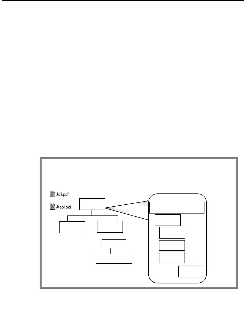
Using the JTAPI SDK
160 Installation Guide
Components of the JTAPI SDK
The JTAPI SDK is the Avaya Computer Telephony implementation of the JAVA Telephony
API. With the JTAPI SDK you can develop JTAPI applications that access the DEFINITY
system using Avaya Computer Telephony. Figure 7-1 depicts the following components of
the JTAPI SDK.
JTAPI Client - These are the JTAPI JAVA classes that you will need to build and execute
your application. Several different packagings are provided. See the packaging
descriptions in Chapter 6 to determine your needs.
Sample Code - Some sample JTAPI application source code.
JTAPI Exerciser - An API exerciser that allows you to create any JTAPI object and execute
its methods without writing any code. A useful learning and testing tool.
DEFINITY G3 PBX Simulator - This simulates telephones as if they are connected to the
telephone switch (PBX). You can test your JTAPI application without a DEFINITY ECS by
using this simulator in conjunction with the Avaya Computer Telephony Server. When
using the Simulator, there will be no audible phone rings. You can see the events that
represent phone rings by using the Simulator Console, which is supplied with the
Simulator.
Figure 7-1: JTAPI SDK at a Glance
JTAPI SDK Components
JTAPI
TOOLS
C:\CLIENT\TSAPI\JTAPI
JTAPI
ALL
DEBUG
TOOLSSAMPLES
Related
documents
TSTEST
JTAPIEX
JTAPI Exerciser
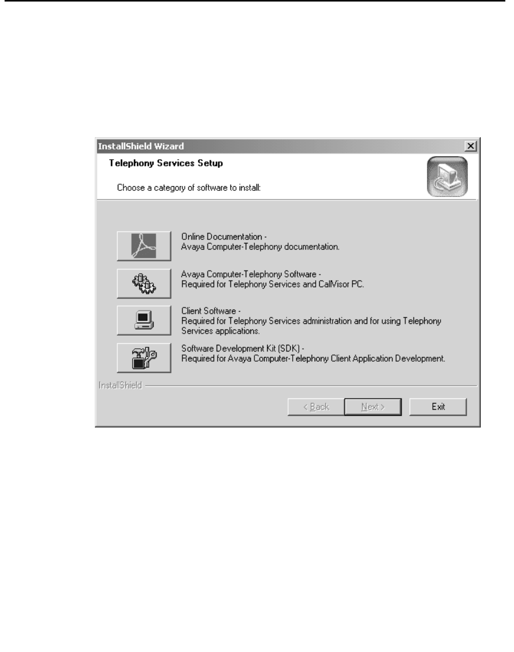
Installing the JTAPI SDK
Issue 1 October 2003 161
Installing the JTAPI SDK
1. Insert the CD into the CD-ROM drive (the Setup program runs automatically if you
have not disabled the AutoRun feature).
2. Setup displays the Telephony Services Setup dialog box.
Figure 7-2: Telephony Services Setup Screen
3. Click on the Software Development Kit (SDK) button.
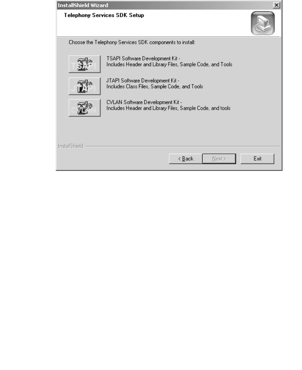
Using the JTAPI SDK
162 Installation Guide
The Telephony Services SDK Setup screen displays

Installing the JTAPI SDK
Issue 1 October 2003 163
4. Click on the JTAPI Software Development Kit button.
The Welcome screen displays.
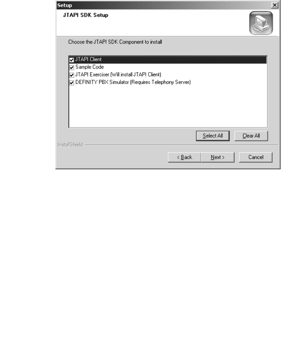
Using the JTAPI SDK
164 Installation Guide
5. Click Next to continue with the installation.
The JTAPI SDK Setup screen displays.
6. Check the appropriate components to install then click Next.
If you have selected the JTAPI Client then the JTAPI Client Welcome Dialog displays.
Refer to ‘‘Installing the JTAPI Client Software in the Windows Environment’’ on page -
151 for more information.
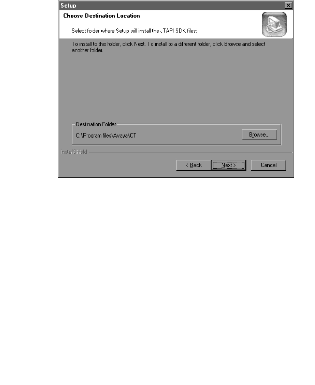
Installing the JTAPI SDK
Issue 1 October 2003 165
The Choose Destination Location screen displays.
7. Accept the default destination folder or use the browse button to select a different
destination location. Click Next.
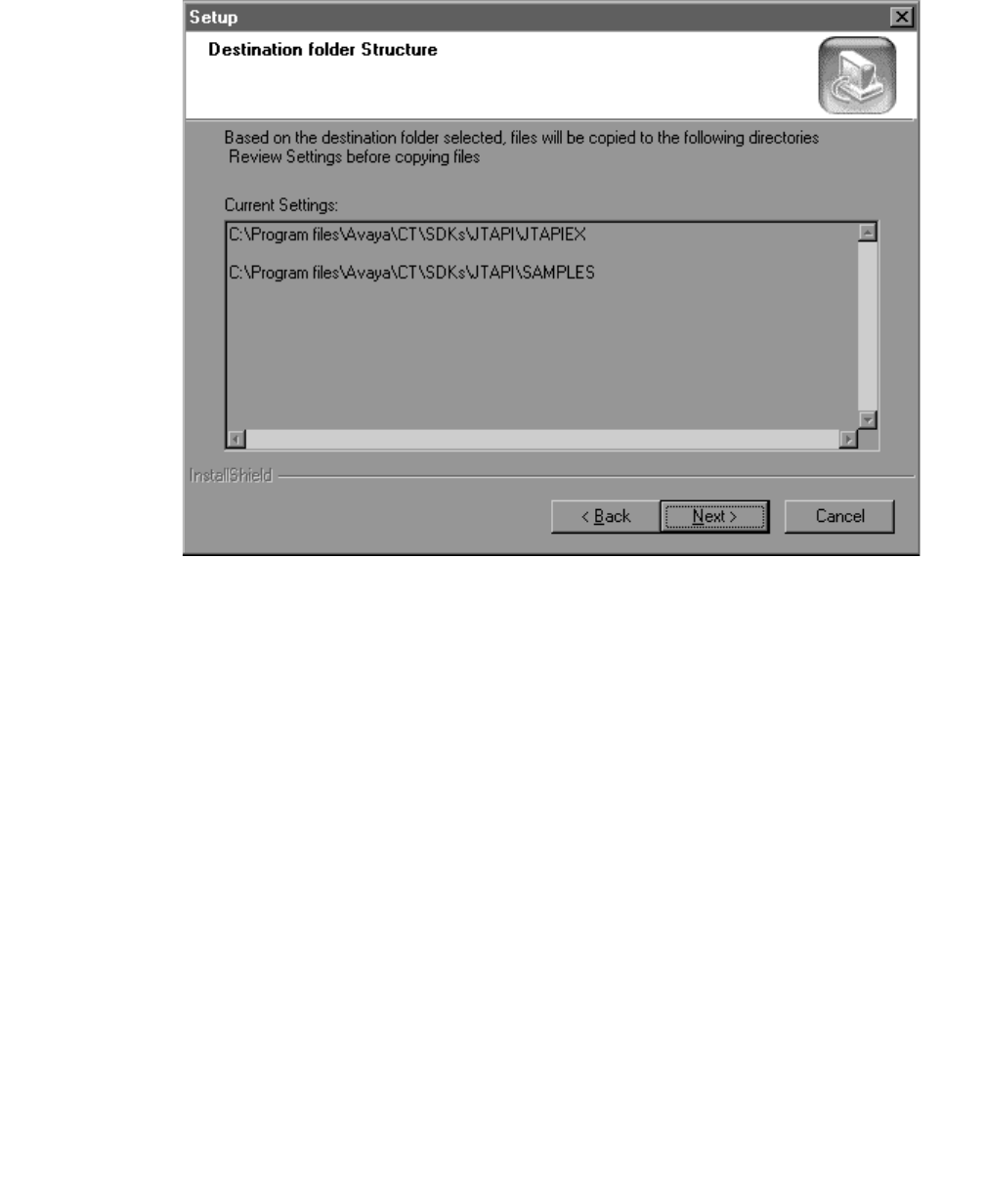
Using the JTAPI SDK
166 Installation Guide
The Destination Folder Structure screen displays.
8. Click Next.
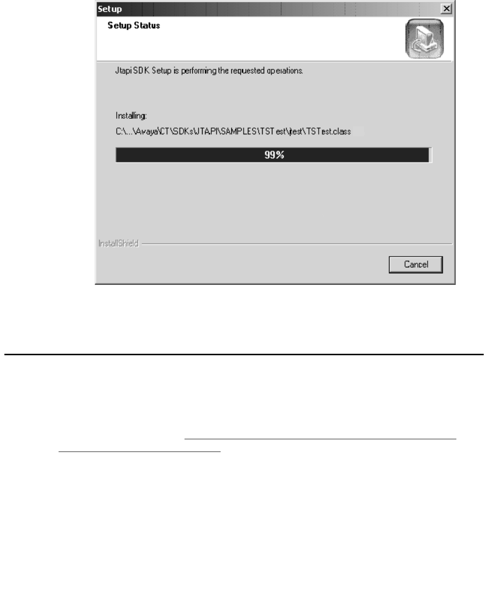
Private Data Versions Supported
Issue 1 October 2003 167
The Installation Status screen displays.
The installation is complete.
Private Data Versions Supported
The Avaya Computer Telephony JTAPI client platform supports DEFINITY Private Data
Version up to Private Data Version 6.
For more information see, Table 1-1: Avaya Computer Telephony Client Platforms -
Private Data Version Compatibility.

Using the JTAPI SDK
168 Installation Guide
Java Client Hardware and Software Requirements
See Table 7-1 for the Java Client Hardware and Software requirements.
Application Development Basics
1. Obtain a JtapiPeer object using the JtapiPeerFactory class. The TsapiPeer class
represents the Avaya JTAPI implementation.
For example:
jtapiPeer = JtapiPeerFactory.getJtapiPeer("com.avaya.jtapi.tsapi.TsapiPeer")
2. Obtain a list of available tlinks by using the getServices() method of the JtapiPeer
class.
For example:
String[] tlinks = jtapiPeer.getServices();
3. Obtain a Provider object using the getProvider() method of the TsapiPeer class.
Specify Tserver TLINK name and Tserver login and password.
For example:
provider = tsapiPeer.getProvider("avaya#cstaserv#csta#myserver;" + "login=user1;" +
"passwd=user1pass;")
Table 7-1: Java Client Hardware and Software Requirements
CPU Any platform that supports Java Virtual Machine
(VM)
RAM Platform-dependent
Disk Space 2 MB
Operating
System Java VM1
Netscape Navigator 3.x or later or
Internet Explorer 4.x or later
1. Any Java Virtual Machine (VM) compatible with the Sun Microsystem Java
specification, Version 1.02 or later.

Running JTAPI Applets
Issue 1 October 2003 169
Note:
Note: The Simulator TLINK name will be "avaya#cstaserv#csta#<your tserver>"
where <your tserver> is the name of the Windows NT, Windows 2000 or
Windows XP server that the Tserver is installed on. The login and passwd
are the user's Windows NT, Windows 2000 or Windows XP login and
password.
4. The methods that return addresses (such as getAdresses() on Provider and
getRouteableAddresses() on CallCenterProvider) will always return an address for the
special string ALL_ROUTE_ADDRESS, which is defined in RouteAddress. However,
an application will be able to successfully register a route for the address only if the
user, on behalf of whom the application is making the request, is administered in the
SDB with the Routing Services Access Group set to 'Any Device'.
5. If your application will run against a Definity EAS switch you can use the addAgent
method on the javax.callcenter.AgentTerminal interface to log in an EAS agent, just let
the ACDAddress field be null.
Running JTAPI Applets
The following instructions describe how to run applets in the popular internet browsers.
Running Applets in Netscape Communicator
Follow these guidelines when running appplets in Netscape Communicator.
1. Make sure the ECSJTAPID.JAR file is in the same directory as your HTML web page.
2. Make sure there is a line in the web page for your java applet to access
ECSJTAPID.JAR, as in <APPLET archive="ECSJTAPID.JAR" code=TsTest>
3. Make sure the ECSJTAPID.JAR is signed with a Verisign Class 3 certificate, so users
who access the web page will be prompted to allow additional privileges.

Using the JTAPI SDK
170 Installation Guide
Running Applets in Internet Explorer
Follow these guidelines when running appplets in Internet Explorer.
1. Make sure the ECSJTAPID.CAB file is in the same directory as your HTML web page.
2. Make sure there are lines in the web page for your java applet to access
ECSJTAPID.CAB, as in
<OBJECT
CLASSID="clsid:278E9392-39B9-11d1-B301-006097B5325A"
CODEBASE="ECSJTAPID.CAB">
</OBJECT>
Additionally, if your applet is in a signed cab such as TSTEST.CAB, make sure there
are lines in the web page to access TSTEST.CAB, as in
<OBJECT
CLASSID="clsid:2EDB26E1-39B7-11d1-B301-006097B5325A"
CODEBASE="tstest.cab">
</OBJECT>
<APPLET CODE=tstest/TSTest>
3. If the web page is using signed cabinets, such as ECSJTAPIA.CAB, the security
settings for Internet Explorer on clients must be set to "Medium" or lower.
4. ECSJTAPIA.CAB is signed with a Verisign Class 3 certificate, so users who access the
web page will be prompted to allow additional privileges.
Note:
Note: When running applets in Internet Explorer 3.x you may only access a
Tserver that is co-located with the web server which hosts the web page for
your applet. However, if you apply Microsoft's Java SDK 2.0 to Internet
Explorer this restriction does not apply.

JTAPI Sample Applications (SDK\Jtapi\OS_Independent\Samples)
Issue 1 October 2003 171
JTAPI Sample Applications
(SDK\Jtapi\OS_Independent\Samples)
With this product, four sample JTAPI applications/applets have been included to help you
get started.
●ACD Applet
●CallLog Application
●TSTest Applet/Application
●Route Applet
Each directory contains both the source and the executable files. Examine the source files
-- *.java and *.html -- for details on the JTAPI interfaces used.
Below, you will find a high-level description of these applications and how to configure your
system to run them. We will be using the ecsjtapid.jar file included on the CD. Also, we will
be using Sun appletviewer included in the Java Development Kit (JDK) available from
JavaSoft at Sun.

Using the JTAPI SDK
172 Installation Guide
ACD Applet
This applet demonstrates the use of the JTAPI Call Center package. It gets the
ACDAddresses known to the provider, and the agents logged-in at those ACD splits. It tries
to log-in two agents specified as parameters in the acd.html file.
To run:
1. CLASSPATH must be modified to include ecsjtapid.jar, and the directory containing the
tsapi.pro file.
2. Modify the tsapi.pro file to include the IP address or hostname of your Tserver. If you
are setting up Avaya Computer Telephony in a Network Address Translation (NAT)
environment, use the IP address administered in the NAT table as the outside address
of the Telephony Server.
3. Modify the acd.html file to customize it for your environment.
You will need to change the following applet parameters:
●SERVICENAME — Advertised name of the CTI link
●LOGIN — NT/Telephony Server user login
●PASSWORD — NT user password
●ACD — Split extension for an ACD administered on your
●PBX
●AGENT1 — Agent for split specified (logged-off)
●AGENT2 — Agent for split specified (logged-off)
4. From the command prompt, type
appletviewer acd.html
CallLog Application
This application uses JTAPI along with some of the Avaya Computer Telephony extensions
to the API to access functionality specific to the DEFINITY G3 PBX.
This application has these purposes:
●Observe a terminal to log all incoming and outgoing calls to/from the specified device. It
also displays UserToUser information, if any, associated with the call.
●The ability to make calls and send UserToUser information along with the call
●The ability to send DTMF through an active call

JTAPI Sample Applications (SDK\Jtapi\OS_Independent\Samples)
Issue 1 October 2003 173
●The ability to disconnect active call
To run:
1. CLASSPATH must be modified to include ecsjtapid.jar, and the directory containing the
tsapi.pro file.
2. Modify the tsapi.pro file to include the IP address or hostname of your Tserver.
3. From the command prompt, type
start java CallLog
TSTest Applet/Application (in the TSTest directory)
Use TSTest to make a call in order to test the installation of the JTAPI client software. It
may be executed as an applet or a stand-alone Java application. Use TSTest to make a
call in order to test the installation of the JTAPI client software. It may be executed as an
applet or a stand-alone Java application.
1. CLASSPATH must be modified to include ECSJTAPID.JAR, and the directory
containing the TSAPI.PRO file.
2. Modify the TSAPI.PRO file to include the IP address or hostname of your Tserver.
3. To run as a standalone java application, from the command prompt, change directory
to TSTest and :start java tstest/TSTest
4. To run TSTest as an applet:
for Netscape -
a. Copy the TSTest directory and the ECSJTAPID.JAR file to the web server.
b. Access the web page navtestd.html to run the applet.
for IE -
c. Copy the IE4Test directory and the ECSJTAPIA.CAB file to the web server.
d. Copy the modified TSAPI.PRO file to the client's java library directory. (On a
Windows NT, Windows 2000 or Windows XP machine this is the java\lib directory.)
e. Access the web page ietstesta.html to run the applet.
Route Applet
This applet demonstrates the use of the JTAPI Call Center package. It is a routing
application which registers the VDN specified in the route.html for routing. When a call is
received by the VDN, the applet requests a route destination. When the route destination is
entered, the call is routed to that destination.

Using the JTAPI SDK
174 Installation Guide
To run:
1. CLASSPATH must be modified to include ecsjtapid.jar, and the directory containing the
tsapi.pro file.
2. Modify the tsapi.pro file to include the IP address or hostname of your Tserver.
3. Modify the route.html file to customize it for your environment. You will need to change
the following applet parameters:
●SERVICENAME — Advertised name of the CTI link
●LOGIN — NT/Telephony Server user login
●PASSWORD — NT user password
●VDN — VDN administered for routing to CTI link
4. From the command prompt, type
appletviewer route.html

The JTAPI Exerciser Application
Issue 1 October 2003 175
The JTAPI Exerciser Application
The JTAPI Exerciser is a Java application that allows you to create JTAPI objects and
invoke their methods interactively.
Manually Installing and Running the JTAPI Exerciser
For Non-Windows operating systems and some special cases on a Windows operating
system a manual install may be necessary. The required files should be copied manually
and can be found on the CD-ROM under this path: \sdks\jtapi\os_independent\. The
JTAPI client classes can be found at this path: \client\jtapi\os_independent\. For specific
system configuration issues see the JTAPI Client readme file.
Follow these steps to manually install and run the JTAPI Exerciser.
1. Copy jtapiex.jar from SDK\Jtapi\OS_Independent\Tools\Jtapiex to a local directory.
2. (Microsoft VM) Unzip the Jtapi class file (ecsjtapia.zip or debug version ecsjtapd.zip) in
the %SystemRoot%\java\lib directory. Also, copy the edited Tsapi.pro to the same
directory.
3. (Microsoft VM) Unjar the Jtapiex.jar file in the %SystemRoot%\java\lib directory.
4. (All other VMs) Copy Jtapi class files and the edited Tsapi.pro to any directory in the
CLASSPATH environment variable:
(Netscape 4.x) ecsjtapia.jar, ecsjtapid.jar
(all others) ecsjtapia.zip, ecsjtapid.zip
5. From the command prompt, type:
start java jtapiex/Jtapiex (Sun JDK)
start jview jtapiex/Jtapiex (Microsoft VM)

Using the JTAPI SDK
176 Installation Guide
Obtaining Version Information
To obtain version information of the JTAPI client software, execute the following command
from the command prompt:
java ECSJtapiVersion
Or in the Windows environment run the application from the JTAPI SDK start menu
shortcut.
JTAPI Online Support
Up to date information, including patches and Frequently Asked Questions are available at
the following URL:
http://www.avaya.com/support/

Issue 1 October 2003 177
Chapter 8: Using the TSAPI SDK
This chapter contains the following sections which provide information for using Telephony
Services Application Programming Interface (TSAPI) Software Development Kit (SDK),
which is included on the Avaya Computer Telephony CD-ROM.
●Overview on page 177
●SDK Online Support on page 178
●Avaya Computer Telephony Installation Instructions for Using the SDK on Windows on
page 178
●High Level View of the TSAPI SDK on page 179
●Installing the TSAPI SDK on page 180
●TSAPI Programming Environment on page 186
●TSAPI Programming Notes on page 187
●Windows NT, Windows 2000 and Windows XP PBX Driver Development Information on
page 188
●TSAPI Sample Code on page 192
Overview
The TSAPI SDK is intended for programmers who are developing Computer Telephony
Integration (CTI) applications in a simulated environment.
The Avaya Computer Telephony SDK provides a programming environment (including a
switch simulator) that enables you to develop the following.
●TSAPI-compliant applications on Win32, and UnixWare
●TSAPI-compliant PBX drivers under Windows NT, Windows 2000 or Windows XP
Note:
Note: The SDK does not provide you with a Driver Authorization file (the G3PD
License File). If you intend to access live PBX resources you must obtain the
DEFINITY Driver Authorization File (G3PD License).

Using the TSAPI SDK
178 Installation Guide
SDK Online Support
Up to date information, including patches and Frequently Asked Questions are available at
the following URL:
http://support.avaya.com/
Under "CTI", select "Avaya Computer Telephony SDK Support".
Avaya Computer Telephony Installation Instructions
for Using the SDK on Windows
From the master Avaya Computer Telephony Installer install the product documentation
and the Avaya Computer Telephony Software. Do not install the DEFINITY G3 PBX Driver
and CallVisor PC software. At the "Server Setup" screen, clear the "DEFINITY G3 PBX
Driver and CallVisor PC" checkbox. After installing the Telephony Server and Security
Database use the master Avaya Computer Telephony Installer to install the TSAPI SDK
components.
Related Documentation
The TSAPI for Avaya MultiVantage Programmer’s Reference Guide contains syntax for
private data versions 2 - 6. The format title of the document is: Avaya Computer Telephony,
Telephony Services Application Programming Interface (TSAPI) for Avaya MultiVantage,
Programmer's Reference Guide (DEFPROG.PDF in the \doc directory of the CD-ROM)
Telephony Services Driver developers should refer to the following documentation for
detailed information about the Telephony Services Driver Interface:
Telephony Services PBX Driver Interface Specification (TSDI.PDF).
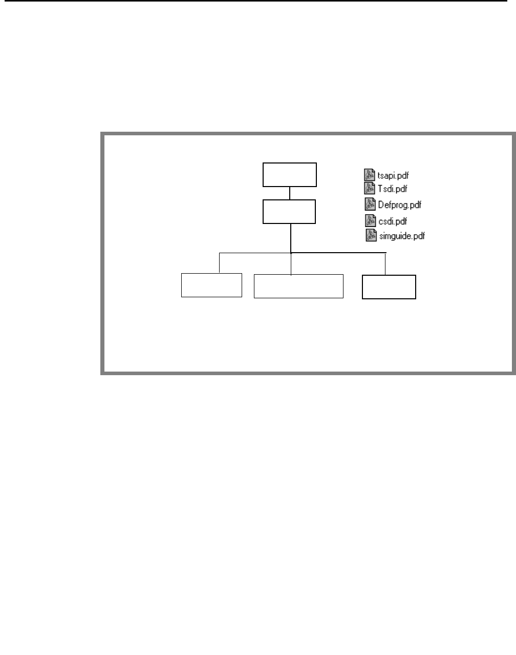
High Level View of the TSAPI SDK
Issue 1 October 2003 179
High Level View of the TSAPI SDK
The TSAPI SDK provides a development environment for programming TSAPI
applications and developing PBX drivers. Figure 8-1 shows the components included in
the TSAPI SDK.
Figure 8-1: SDK at a Glance
SDK
TSAPI
WINDOWS
Related
documents
SOLARIS SPARC
UNIXWARE
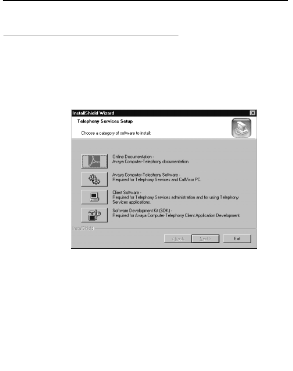
Using the TSAPI SDK
180 Installation Guide
Installing the TSAPI SDK
Installing in the Windows Environment
1. Insert the CD into the CD-ROM drive (the Setup program runs automatically if you
have not disabled the AutoRun feature).
2. Setup displays the Telephony Services Setup dialog box.
Figure 8-2: Telephony Services Setup Screen
3. Click on the Software Development Kit (SDK) button.
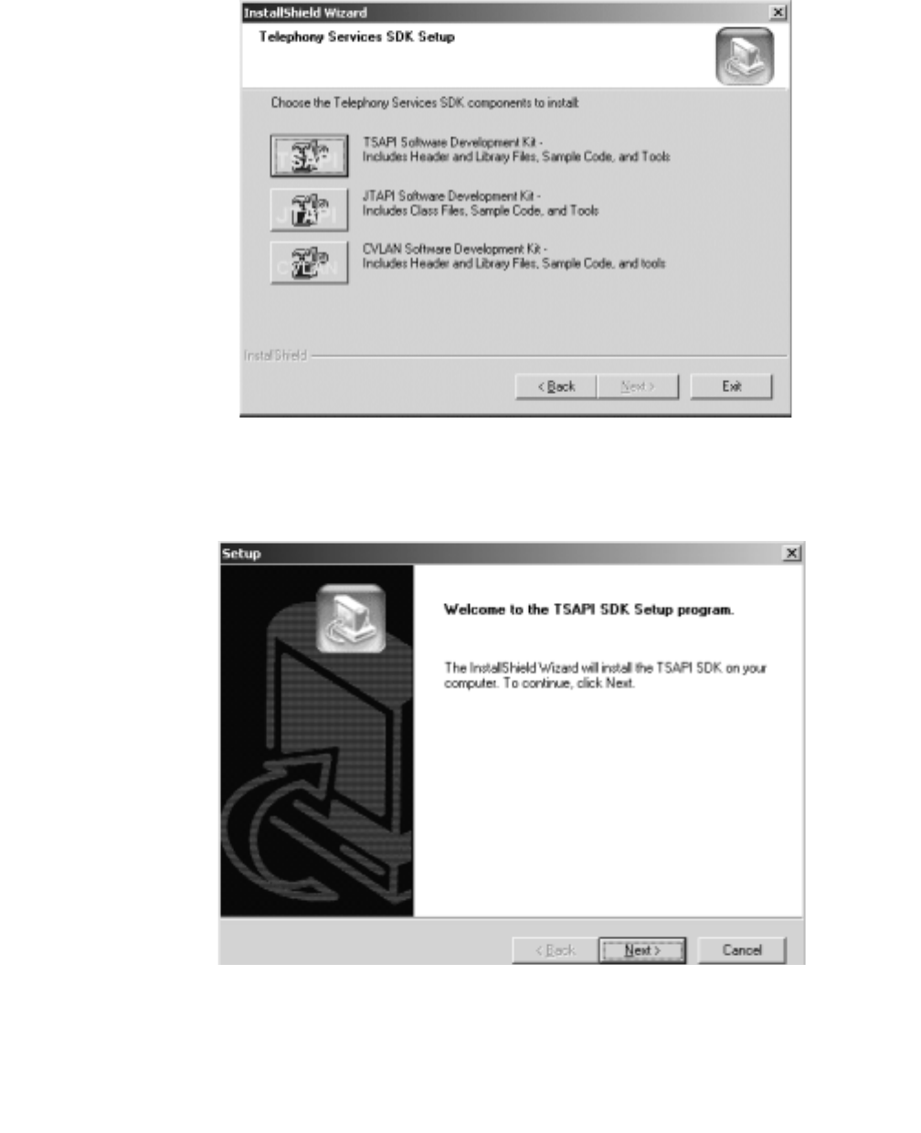
Installing the TSAPI SDK
Issue 1 October 2003 181
Figure 8-3: Telephony Services SDK Setup Screen
4. Click on the TSAPI Software Development Kit (SDK) button.
Figure 8-4: Welcome Screen
5. Click Next.
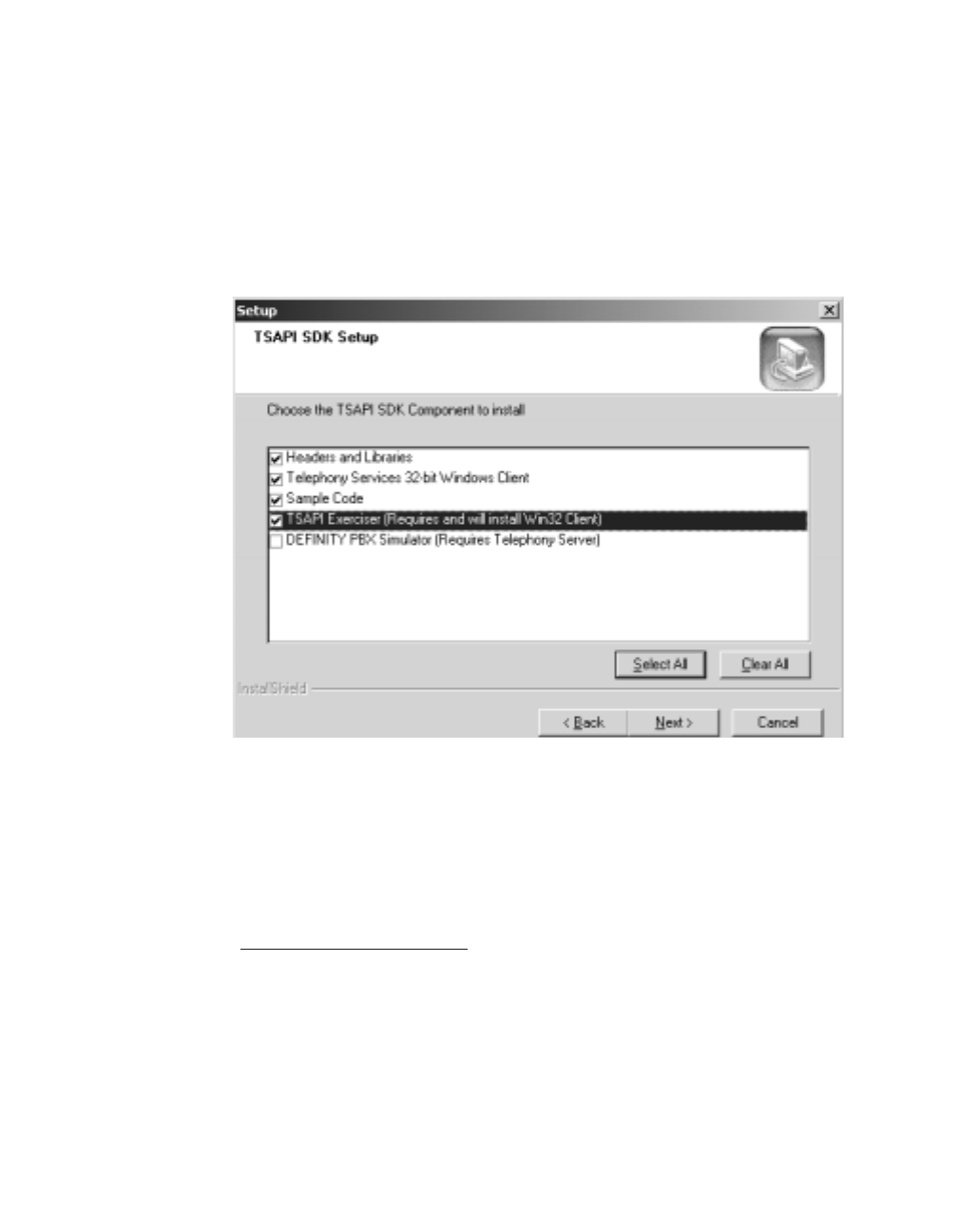
Using the TSAPI SDK
182 Installation Guide
Note:
Note: At this time a search for previous versions/components is conducted so
processing may take a few minutes. If a previous version is found, a
message displays asking you if you would like to continue with the
installation. Having multiple versions installed is allowed and you may
continue without uninstalling. It is recommended that you uninstall the
previous version to avoid confusion. Uninstall directions are displayed.
If you continue with the installation procedure the following screen displays.
Figure 8-5: TSAPI SDK Setup Screen
6. Check the appropriate components to install then click Next.
Note:
Note: If the Telephony Services 32-bit Windows client was selected to be installed,
the Setup screen displays. Refer to ‘‘Installing the Windows Client Software’’
on page -101 for more information.
If the Definity PBX Simulator was selected to be installed, the Setup screen displays.
Refer to Specialized Installations in Chapter 3 for more information about installing the
Definity PBX Simulator.
The installation of the TSAPI SDK continues.
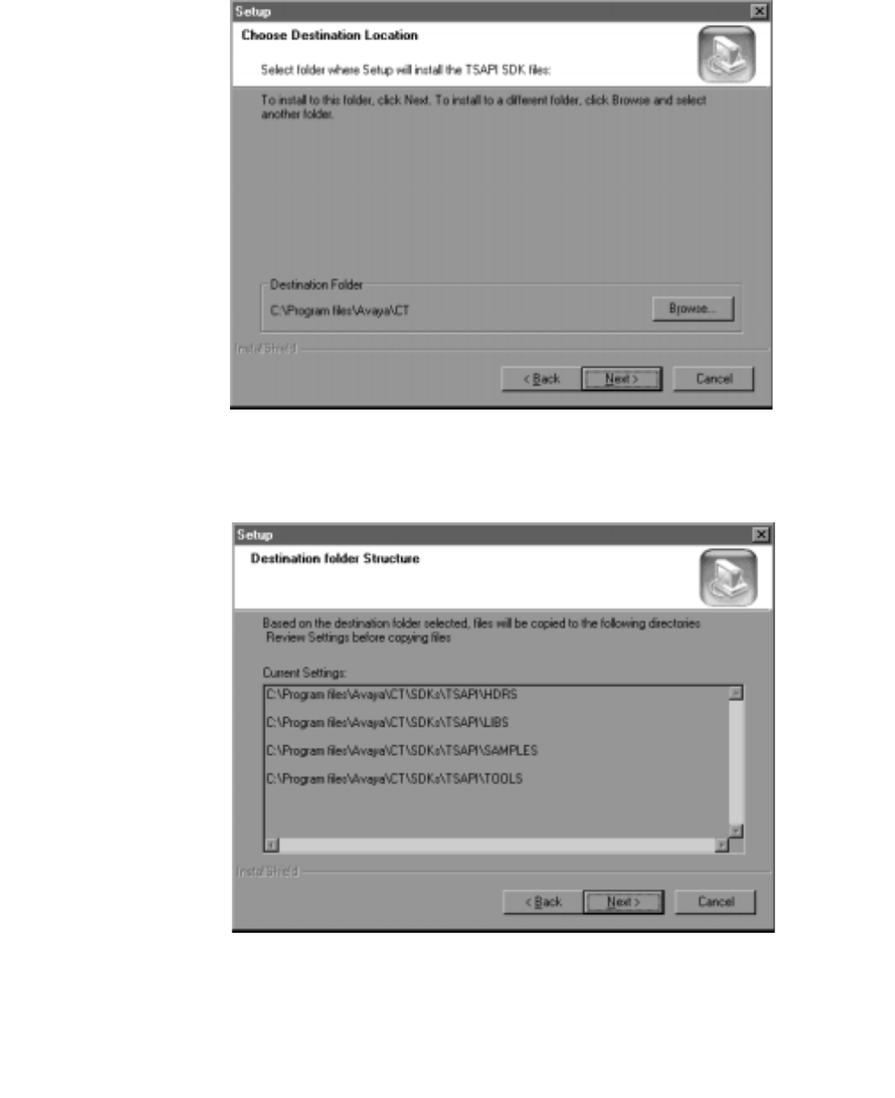
Installing the TSAPI SDK
Issue 1 October 2003 183
Figure 8-6: Destination Location Screen
7. Accept the default destination location and click Next to continue.
Figure 8-7: Destination Folder Structure Screen
8. Review settings and click Next.
The Installation is now complete.

Using the TSAPI SDK
184 Installation Guide
Installing in the Unixware Environment
Installing from the CD:
1. Become super-user (root): su
2. Enter the root password when prompted.
3. Insert the Telephony Services CD-ROM into your workstation CD-ROM drive.
4. At the command prompt, mount the CD-ROM as follows:
mount -F cdfs -r /dev/cdrom/device /mountpoint
where device specifies the CD-ROM drive that contains the Telephony Services
installation disk and mountpoint is the name of an existing directory (such as /cdrom1
or /CD-ROM_1) on which to mount the CD-ROM. You can use the ls command to find
the appropriate name for your system.
Desktop users may find it easier to mount the CD-ROM by double-clicking on the CD-
ROM icon in the "Disks-etc" folder.
5. At the command prompt, enter the pkgadd command as follows:
pkgadd -d /mountpoint/sdk/tsapi/unixware/nwtssdk.spl
where mountpoint is as described above. (Note: the full pathname, beginning with a ‘/
’, is required.)
6. Select package to install.
The system now displays a list of the packages on the CD-ROM.
Press <Enter> to select the nwtssdk package.
7. Read the Telephony Services SDK "readme" file.
The pg command displays the Telephony Services SDK "readme" file, tslib.readme.
This file contains information about changes that were made after the manuals were
completed. Read this information until you reach the end of the file.
8. The installation is complete. Unmount the CD-ROM as follows:
umount /dev/cdrom/device
where device is the same as in Step 3.
You may now remove the CD-ROM.

Installing the TSAPI SDK
Issue 1 October 2003 185
Installing in the Solaris Environment
1. At the command prompt, enter the pkgadd command as follows:
pkgadd -d /cdrom/cdrom0/SDK/tsapi/sparc/tsapisdk.spl
2. At the enter path to package base directory prompt, enter
/usr/include/nts (or the directory of your choice)
Installing in the HP-UX Environment
3. Become super-user (root): su
4. Enter the root password when prompted.
5. Insert the Telephony Services CD-ROM into your workstation CD-ROM drive.
6. At the command prompt, mount the CD-ROM as follows:
mount -F cdfs -r /dev/cdrom/device /mountpoint
where device specifies the CD-ROM drive that contains the Telephony Services
installation disk and mountpoint is the name of an existing directory (such as /cdrom1
or /CD-ROM_1) on which to mount the CD-ROM. You can use the ls command to find
the appropriate name for your system.
7. Desktop users may find it easier to mount the CD-ROM by double-clicking on the CD-
ROM icon in the "Disks-etc" folder.
8. At the command prompt, enter the swinstall command as follows:
swinstall -s/<mountpoint>/SDK/TSAPI/HPUX/TSSDK.TAR\;1

Using the TSAPI SDK
186 Installation Guide
TSAPI Programming Environment
This section summarizes the contents of the SDK\TSAPI subdirectories.
"Hdrs" Directory (SDKs\TSAPI\HDRS)
This directory contains header files for the TSAPI SDK.Two files are of particular
importance, "attpriv.h" and "attpdefs.h," which are for the DEFINITY G3(ATT)private data
version 6 SDK.
About the Private Data Version Files
If your current TSAPI applications were written against earlier versions of the SDK they will
not handle DEFINITY G3 private data correctly if they are simply recompiled with this
version of the SDK. Here are some guidelines for upgrading your application.
●If you want to recompile your existing applications using this version of the SDK, search
in attprivs.h and attpdefs.h for the string "ATTV5."
●Typedefs and constants that have been changed in support of private data version 6
have been preserved with the preface "ATTV5."
●Your application will have to be upgraded if you wish to continue to use these typedefs
and constants.
Libs (SDKs\TSAPI\LIBS)
This directory contains the CSTA32.LIB and ATTPRIV32.LIB import libraries. These are
private data version 6 files.
Samples (SDKs\TSAPI\SAMPLES)
This directory contains samples of complete applications that demonstrate how to program
to TSAPI.

TSAPI Programming Notes
Issue 1 October 2003 187
Tools (SDKs\TSAPI\TOOLS)
This directory contains the Tsapi Exerciser program.
Win32 (SDKs\TSAPI\Windows)
This directory contains the CSTA32.LIB and ATTPRIV32.LIB import libraries. These are
private data version 6 files.
TSAPI Programming Notes
Closing Streams Before Exit
Your application must close all open streams -- preferably by calling acsAbortStream() --
before exiting.
acsCloseStream()
You must retrieve the ACSCloseStreamConfEvent by calling acsGetEventBlock() or
acsGetEventPoll() if you use acsCloseStream(). Unless your application needs to see the
ACSCloseStreamConfEvent, e.g. the PBX driver sends private data with the close
confirmation in which you are interested, you should use acsAbortStream() instead.
DEFINITY Private Data Name Change
DEFINITY Private Data is the name of the software formerly called AT&T Private Data. All
functions formerly contained in AT&T Private Data are provided by DEFINITY Private Data
and the file names are the same.

Using the TSAPI SDK
188 Installation Guide
Version Negotiation
When opening a stream, an application may negotiate with a PBX driver to agree upon the
version of private data protocol to be used (as described in "Private Data Version Control"
in the TSAPI for Avaya MultiVantage Programmer's Guide It is also important that the
DEFINITY private data library can support this protocol. To ensure this and to assist in the
construction of a proper version string, the attMakeVersionString() API may be used.
This function accepts a string containing the numerical range of versions supported by the
application, e.g., "1-3", and returns (in a caller-supplied buffer) a "filtered" string to be
passed in the version negotiation, e.g., "AT&T Definity G3#2".
This string includes the vendor name, and represents the intersection of those versions
supported by both the application and the DEFINITY private data library. Upon success,
the function returns the length of the output string (not including terminating NULL). The
function may fail with return value ACSERR_BADPARAMETER if the input string is ill-
formed, or, if no requested version is supported by the library, may return
ACSERR_APIVERDENIED.
Windows NT, Windows 2000 and Windows XP PBX
Driver Development Information
This section contains important information for developers creating TSAPI client
applications and Telephony Services PBX drivers.
Linkage Notes
●The TDI.LIB import library was generated by Microsoft Visual C++. If your development
system does not support the Microsoft library format, you must consult its
documentation to determine how to create an equivalent import library from TDI.DLL.
Alternatively, you can dynamically import the TSDI via LoadLibrary () and
GetProcAddress () or use some other symbol import method.
●We recommend Microsoft Visual C++ for developing PBX Drivers.
Avaya Computer Telephony R11.1 V1 requires that you use Microsoft Visual C++ 6.0
for developing PBX drivers and Windows .EXE applications.

Windows NT, Windows 2000 and Windows XP PBX Driver Development Information
Issue 1 October 2003 189
PBX Driver Installation
Telephony Services for NT installs INSTTSDR.DLL, a utility library for PBX driver
installation.
INSTTSDR.DLL exports a function called installTelephonyServicesDriver(). Your PBX
driver's installation routine may call this function in order to add the driver's name to the
Tserver's list of drivers.
The INSTTSDR.H header file specifies the C-language interface to the functions in
INSTTSDR.DLL.
installTelephonyServicesDriver() is a convenience routine so that the user does not have to
manually add the driver to the Tserver's list of administered drivers via TSA.
You may not include INSTTSDR.DLL with your PBX driver; rely on the Telephony Server to
provide this file.
Sample Code
Figure 8-8: Sample Code on page 190 provides sample code for using the
installTelephonyServicesDriver() function with a popular installer, InstallShield3.

Using the TSAPI SDK
190 Installation Guide
Figure 8-8: Sample Code
prototype INSTTSDR.installTelephonyServicesDriver
(BYREF STRING, NUMBER);
InstallAsTserverDriver:
// Add the driver.dll to the tservers registry entry
// as a driver and have it auto loaded when
// Tserver restarts.
nRc = UseDLL(WINSYSDIR^"INSTTSDR.DLL");
if (nRc < 0) then
// Couldn't load the insttsdr dll...
// Tserver probably wasn't installed...
SprintfBox(WARNING, "Install Problem",
"Installation was unable to enter the driver.dll "+
"in the Telephony Services list of drivers "+
"(Possibly because the Telephony Services "+
"product is not installed yet). "+
"You will have to perform this function manually "+
"through the Telephony Services Administrator "+
"application.");
else
svDriverName = "driver.dll";
nRc = installTelephonyServicesDriver
(svDriverName,TSDR_AUTOLOAD);
// Only put up the warning if it wasn't success
// and it wasn't a duplicate entry.
if (nRc < TSDR_DUPLICATE) then
SprintfBox( WARNING, "Install Problem",
"Installation was unable to enter the driver.dll "+
"in the Telephony Services list of drivers "+
"(Possibly because the Telephony Services product"+
"is not installed yet). "+
"You will have to perform this function "+
"manually through the Telephony Services "+
"Administrator application.");
endif;
UnUseDLL(WINSYSDIR^"INSTTSDR.DLL");
endif;

Windows NT, Windows 2000 and Windows XP PBX Driver Development Information
Issue 1 October 2003 191
CSTA Server
The CSTA Server DLL provides an alternate PBX driver interface, called the CSTA
Services [PBX] Driver Interface (CSDI), for use in passing CSTA request, response, and
event messages between a PBX Driver and the Telephony Server.
The CSTA Server is always loaded by the Telephony Server. CSDI compliant drivers do
not need to load any additional software to load their drivers.
Driver Debugging Strategies
The Tserver runs as an NT Service which makes debugging PBX drivers difficult. This SDK
includes an executable version of the Tserver (TSRVSDK.EXE) which may be useful in
developing and debugging your PBX Driver. This executable still requires all of the
supporting DLLs as does the Service version of the Tserver (TSRV.EXE). A good way to
install TSRVSDK.EXE is to place it in the same directory as TSRV.EXE.
Note:
Note: TSRVSDK.EXE does not call tdiStopDriver(), the Driver's unload function.
You must test your PBX driver with TSRV.EXE running as a service to test
your unload routine.
To test PBX driver unload, stop the TSAPI Telephony Services Service from the Services
control panel. If an error occurs indicating that the Tserver did not respond to the stop
request, verify that nothing in the Driver's tdiStopDriver() function is hanging. Look in the
Tserver Error Log for an entry "UNLDDRV: Freeing the library <drivername.dll>". This entry
indicates that the Tserver called the Driver's tdiStopDriver() function and received a
successful result (TRUE) from the Driver. If this message is not in the Error Log then the
Driver is hung somewhere in its unload function. The Tserver will not finish unloading until
the Driver does.
Note:
Note: The Driver must not return from the tdiStopDriver() function until it has
completely stopped all of its threads and cleaned up all of its resources. If
the Driver still has something running after it returns from tdiStopDriver(),
TSRV.EXE will abnormally terminate because the Tserver frees the driver
library upon a successful return from tdiStopDriver(). If the Driver tries to
access memory after it has been freed, abnormal termination will occur.

Using the TSAPI SDK
192 Installation Guide
TSAPI Sample Code
In a Windows installation, the sample code can be located through the Avaya Computer
Telephony TSAPI SDK entry in the Start menu. The TSAPI samples provided are complete
applications that demonstrate how to program to TSAPI. Each of these samples builds on
the next, with each one implementing more TSAPI functionality than the previous one.
These samples were all written in C++ and built using the Microsoft Developer Studio and
the Microsoft Foundation Classes (MFC). The makefiles (*.MDP and *.MAK) provided with
this sample are specific to that development environment. However, no complex C++ or
MFC techniques were used and there are comments explaining the MFC code to non-MFC
folks.
Porting this code to other platforms will require modifications to event notification.
These samples build on each other in the following order:
1. TSAPIOUT - TSAPI Outgoing Call Handling
1 device, 1 call Shows basic outgoing call handling for a single device and a single call
with no redirection, conferencing, transferring, etc. Includes making a call and hanging
up the call.
2. TSAPIIN - TSAPI Incoming Call Handling
1 device, 1 call Adds incoming call handling to sample 1. Still no redirection,
conferencing, etc. It demonstrates differentiating between incoming calls and outgoing
calls. Includes answering calls.
3. TSAPIMUL - TSAPI Multiple Call Handling
1 device, many calls Adds multiple call handling to sample 2. It demonstrates how to
keep track of multiple calls at the same device. Includes holding and retrieving calls.
Also includes redirection as a bonus.
4. TSAPICNF - TSAPI Conference Call Handling
1 device, many calls Adds conference/transfer handling to sample 3. Includes tracking
of many connections on a single call.
The following files are common to all of the samples:
TSAPI.CPP
TSAPI.H
helper classes for tracking devices and calls and routines for retrieving TSAPI events
from the CSTA DLL
OPENTSRV.CPP
OPENTSRV.H
supports the Open Tserver dialog; authorizes the user, opens the TSAPI stream and
registers the selected device with the TSAPI helper classes.

TSAPI Sample Code
Issue 1 October 2003 193
SAMPLDLG.CPP
SAMPLDLG.H
supports the main application dialog; all call-related control is here: making calls,
answering calls, call event handling, etc.
STDAFX.CPP
STDAFX.H
MFC files that do not contain any interesting code for the purposes of TSAPI-code
demonstration
RESOURCE.H
resource IDs for the application
The following files contain similar functionality in each sample, but are named unique to
each sample:
TSAPIOUT.CPP
TSAPIOUT.H
TSAPIOUT.RC
initialization and resources for sample 1
TSAPIIN.CPP
TSAPIIN.H
TSAPIIN.RC
initialization and resources for sample 2
TSAPIMUL.CPP
TSAPIMUL.H
TSAPIMUL.RC
initialization and resources for sample 3
TSAPICNF.CPP
TSAPICNF.H
TSAPICNF.RC
initialization and resources for sample 4

Using the TSAPI SDK
194 Installation Guide
For More Information
For more information about the TSAPI SDK, see the TSAPI SDK Readme file (SDK
Readme (<DriveID>:\Readmes\TSAPI SDK Readme.txt)

Issue 1 October 2003 195
Appendix A: Avaya Computer Telephony
Installed Files
This appendix lists the files that Avaya Computer Telephony installs. It list files associated
with the following components.
●Avaya CT Server
●G3PBX Driver
●Win 32 Client
●UnixWare Client
●HP-UX Client
Drive designations in the Tables A-1 through A-4 are depicted as "C:\" by convention. This
drive designation can vary according to the requirements of your system.

Avaya Computer Telephony Installed Files
196 Installation Guide
Avaya CT Server
When Avaya CT server software is installed, the files listed in Table A-1 are copied to your
server’s hard drive.
Table A-1: Telephony Server Files
File Name Destination Directory
Uninstsrvc.dll C:\Program Files\Avaya\CT\tsrv\Program
Tsconfig.exe C:\Program Files\Avaya\CT\tsrv\Program
Tsctrl.exe C:\Program Files\Avaya\CT\tsrv\Program
Cserver.dll C:\Program Files\Avaya\CT\tsrv\Program
Migrate.exe C:\Program Files\Avaya\CT\tsrv\Program
Server
Readme.txt C:\Program Files\Avaya\CT\tsrv
Tsstart.exe C:\Program Files\Avaya\CT\tsrv\Program
Tssdb.dll C:\Program Files\Avaya\CT\tsrv\Program
Tsrvbtrv.dll C:\Program Files\Avaya\CT\tsrv\Program
Tslogin.exe C:\Program Files\Avaya\CT\tsrv\Program
Tslogsrv.exe C:\Program Files\Avaya\CT\tsrv\Program
Tsrv.exe C:\Program Files\Avaya\CT\tsrv\Program
Trafcop.exe C:\Program Files\Avaya\CT\tsrv\Program
TSTraf.dll C:\Program Files\Avaya\CT\tsrv\Program
Tsusr.dll C:\Program Files\Avaya\CT\tsrv\Program
Tsvl.dll C:\Program Files\Avaya\CT\tsrv\Program
Tsauth.dll C:\Program Files\Avaya\CT\tsrv\Program
Tsadv.dll C:\Program Files\Avaya\CT\tsrv\Program
Tsevtlog.dll C:\Program Files\Avaya\CT\tsrv\Program
Tsconfig.hlp C:\Program Files\Avaya\CT \tsrv\Program
Tsmapd.dll C:\Winnt\system32
Tapiinst.dll C:\Winnt\system32
Tdi.dll C:\Winnt\system32

Avaya CT Server
Issue 1 October 2003 197
Tslog.dll C:\Winnt\system32
Insttsdr.dll C:\Winnt\system32
Tsmi.dll C:\Winnt\system32
Table A-1: Telephony Server Files
File Name Destination Directory

Avaya Computer Telephony Installed Files
198 Installation Guide
G3PBX Driver Files
When G3PBX Driver is installed, the files listed in Table A-2 and Table A-3 are copied to
your server’s hard drive.
Table A-2: G3PBX Driver Files
File Name Destination Directory
attprv32.dll C:\Winnt\system32 Used by CVLAN
and G3PBX
Driver
asaidll.dll C:\Winnt\system32 The private data
encoding/
decoding library
needed for the
G3PD to run.
g3pd.dll C:\Winnt\system32 The G3 PBX
Driver (G3PD)
g3instal.dll C:\Program Files\Avaya\CT\G3PD
G3lc.exe C:\Program Files\Avaya\CT\G3PD
g3trace.exe C:\Program Files\Avaya\CT\G3PD
g3peek.exe C:\Program Files\Avaya\CT\G3PD
cvlan.exe C:\Program Files\Avaya\CT\G3PD
esai_trace.exe C:\Program Files\Avaya\CT\G3PD
asai_trace.exe C:\Program Files\Avaya\CT\G3PD
ASAISRVC.exe C:\Program Files\Avaya\CT\G3PD
api.msg C:\Program Files\Avaya\CT\G3PD
G3pd.lic C:\Program Files\Avaya\CT\G3PD G3pdlic is
created when
you install the
license.
Server
Readme.txt C:\Program Files\Avaya\CT\G3PD

G3PBX Driver Files
Issue 1 October 2003 199
Table A-3: G3PBX Driver Configuration Files
File Name Destination Directory
data1.cab C:\Program Files\Avaya\CT\G3PD\g3config
data1.hdr C:\Program Files\Avaya\CT\G3PD\g3config
data2.cab C:\Program Files\Avaya\CT\G3PD\g3config
ikernel.ex C:\Program Files\Avaya\CT\G3PD\g3config
layout.bin C:\Program Files\Avaya\CT\G3PD\g3config
Setup.exe C:\Program Files\Avaya\CT\G3PD\g3config
Setup.ini C:\Program Files\Avaya\CT\G3PD\g3config
setup.inx C:\Program Files\Avaya\CT\G3PD\g3config
tools.ico C:\Program Files\Avaya\CT\G3PD\g3config

Avaya Computer Telephony Installed Files
200 Installation Guide
Win32 Client Files
When Win32 Telephony Services Client is installed, the files listed in Table A-4 are copied
to your client’s hard drive.
Table A-4: Files Copied to Win32 Client
File Name Destination Directory Installation
Conditions
ATTPRV32.DLL Windows System directory
CSTA32.DLL Windows System directory
TSINST32.DLL C:\Program Files\Avaya\CT \TS
Win32\Program
TSSPY32.EXE C:\Program Files\ Avaya\CT\TS
Win32\Program
TSA32.EXE C:\Program Files\Avaya\CT\TS
Win32\Program Administrator
only
TSA32.HLP C:\Program Files\Avaya\CT\TS
Win32\Program Administrator
only
TSM32.HLP C:\Program Files\Avaya\CT\TS
Win32\Program Administrator
only
TSM32.EXE C:\Program Files\Avaya\CT\TS Win
32\Program Administrator
only
TSTEST32.EXE C:\Program Files\Avaya\CT\TS Win
32\Program
WG3OAM.EXE C:\Program Files\Avaya\CT\TS Win
32\Program Administrator
only
WG3OAM.HLP C:\Program Files\Avaya\CT\TS Win
32\Program Administrator
only
TSLIB.INI Windows directory
Client Readme.txt C:\Program Files\Avaya\CT\TS Win
32\Program

UnixWare Client
Issue 1 October 2003 201
UnixWare Client
When Telephony Services is installed on a UnixWare client, the files listed in Table A-5 are
copied to your client’s hard drive.
Table A-5: Files Copied to UnixWare Client
File Name Destination
/usr/lib/attpriv.so Client hard
drive
/usr/lib/libcsta.so Client hard
drive
/usr/lib/tslibrc Client hard
drive
/usr/lib/tstest Client hard
drive
/usr/lib/
tslib.readme Client hard
drive

Avaya Computer Telephony Installed Files
202 Installation Guide
HP-UX Client
When Telephony Services is installed on a HP-UX client, the files listed in Table A-6 are
copied to your client’s hard drive.
Table A-6: Files Copied to HP-UX Client
File Name Destination
/usr/lib/attpriv.sl Client hard
drive
/usr/lib/libcsta.sl Client hard
drive
/usr/lib/tstest Client hard
drive
/usr/lib/tslibrc Client hard
drive

JTAPI Client
Issue 1 October 2003 203
JTAPI Client
When the JTAPI Client software is installed, the files in the following table are copied to the
client’s hard drive.
File Name Destination Directory
Ecsjtapi.zip C:\Program Files\Avaya\CT\Jtapi
Ecsjtapi.cab C:\Program Files\Avaya\CT\Jtapi
Ecsjtapi.jar C:\Program Files\Avaya\CT\Jtapi
Jtapi Client Readme.txt C:\Program Files\Avaya\CT\Jtapi
Simsdb.txt C:\Program Files\Avaya\CT\Jtapi
Ecsjtapi.zip C:\Program Files\Avaya\CT\Jtapi\All
Ecsjtapi.cab C:\Program Files\Avaya\CT\Jtapi\All
Ecsjtapi.jar C:\Program Files\Avaya\CT\Jtapi\All
Ecsjtapi.zip C:\Program Files\Avaya\CT\Jtapi\Debug
Ecsjtapi.cab C:\Program Files\Avaya\CT\Jtapi\Debug
Ecsjtapi.jar C:\Program Files\Avaya\CT\Jtapi\Debug
tstest.cab C:\Program Files\Avaya\CT\Jtapi\Tools\Tstest
tstext.html C:\Program Files\Avaya\CT\Jtapi\Tools\Tstest
AppletFrame$SymWindow.class C:\Program
Files\Avaya\CT\Jtapi\Tools\Tstest\jtest
AppletFrame.class C:\Program
Files\Avaya\CT\Jtapi\Tools\Tstest\jtest
TraceFrame$SymComponent.class C:\Program
Files\Avaya\CT\Jtapi\Tools\Tstest\jtest
TraceFrame$SymWindow.class C:\Program
Files\Avaya\CT\Jtapi\Tools\Tstest\jtest
TraceFrame.class C:\Program
Files\Avaya\CT\Jtapi\Tools\Tstest\jtest
TSTest$SymAction.class C:\Program
Files\Avaya\CT\Jtapi\Tools\Tstest\jtest
TSTest$SymFocus.class C:\Program
Files\Avaya\CT\Jtapi\Tools\Tstest\jtest

Avaya Computer Telephony Installed Files
204 Installation Guide
TSTest$SymItem.class C:\Program
Files\Avaya\CT\Jtapi\Tools\Tstest\jtest
TSTest$SymKey.class C:\Program
Files\Avaya\CT\Jtapi\Tools\Tstest\jtest
TSTest.class C:\Program
Files\Avaya\CT\Jtapi\Tools\Tstest\jtest
File Name Destination Directory

JTAPI SDK
Issue 1 October 2003 205
JTAPI SDK
When the JTAPI SDK software is installed, the files in the following table are copied to the
client’s hard drive.
File Name Destination Directory
Jtapi SDK Reame.txt C:\Program Files\Avaya\CT\SDKs\Jtapi
jtapiex.jar C:\Program
Files\Avaya\CT\SDKs\Jtapi\Jtapiex
AppletFrame.java C:\Program
Files\Avaya\CT\SDKs\Jtapi\Samples\TSTest
TraceFrame.java C:\Program
Files\Avaya\CT\SDKs\Jtapi\Samples\TSTest
tstest.html C:\Program
Files\Avaya\CT\SDKs\Jtapi\Samples\TSTest
TSTest.java C:\Program
Files\Avaya\CT\SDKs\Jtapi\Samples\TSTest
MyRouteCallback.class C:\Program
Files\Avaya\CT\SDKs\Jtapi\Samples\Route
MyTextArea.class C:\Program
Files\Avaya\CT\SDKs\Jtapi\Samples\Route
MyTextArea.java C:\Program
Files\Avaya\CT\SDKs\Jtapi\Samples\Route
Route$SymComponent.class C:\Program
Files\Avaya\CT\SDKs\Jtapi\Samples\Route
Route.class C:\Program
Files\Avaya\CT\SDKs\Jtapi\Samples\Route
route.html C:\Program
Files\Avaya\CT\SDKs\Jtapi\Samples\Route
Route.java C:\Program
Files\Avaya\CT\SDKs\Jtapi\Samples\Route
RoutetoDialog$SymAction.class C:\Program
Files\Avaya\CT\SDKs\Jtapi\Samples\Route
RoutetoDialog$SymComponent.class C:\Program
Files\Avaya\CT\SDKs\Jtapi\Samples\Route
RoutetoDialog$SymFocust.class C:\Program
Files\Avaya\CT\SDKs\Jtapi\Samples\Route

Avaya Computer Telephony Installed Files
206 Installation Guide
RoutetoDialog$SymKey.class C:\Program
Files\Avaya\CT\SDKs\Jtapi\Samples\Route
RoutetoDialog$SymWindow.class C:\Program
Files\Avaya\CT\SDKs\Jtapi\Samples\Route
RoutetoDialog.class C:\Program
Files\Avaya\CT\SDKs\Jtapi\Samples\Route
RoutetoDialog.java C:\Program
Files\Avaya\CT\SDKs\Jtapi\Samples\Route
CallLog$SymAction.class C:\Program
Files\Avaya\CT\SDKs\Jtapi\Samples\CallLog
CallLog$SymComponent.class C:\Program
Files\Avaya\CT\SDKs\Jtapi\Samples\CallLog
CallLog$SymItem.class C:\Program
Files\Avaya\CT\SDKs\Jtapi\Samples\CallLog
CallLog$SymWindow.class C:\Program
Files\Avaya\CT\SDKs\Jtapi\Samples\CallLog
CallLog.class C:\Program
Files\Avaya\CT\SDKs\Jtapi\Samples\CallLog
CallLog.java C:\Program
Files\Avaya\CT\SDKs\Jtapi\Samples\CallLog
DTMFDialog$SymAction.class C:\Program
Files\Avaya\CT\SDKs\Jtapi\Samples\CallLog
DTMFDialog$SymFocus.class C:\Program
Files\Avaya\CT\SDKs\Jtapi\Samples\CallLog
DTMFDialog$SymKey.class C:\Program
Files\Avaya\CT\SDKs\Jtapi\Samples\CallLog
DTMFDialog$SymWindow.class C:\Program
Files\Avaya\CT\SDKs\Jtapi\Samples\CallLog
DTMFDialog.class C:\Program
Files\Avaya\CT\SDKs\Jtapi\Samples\CallLog
DTMFDialog.java C:\Program
Files\Avaya\CT\SDKs\Jtapi\Samples\CallLog
LoginDialog$SymAction.class C:\Program
Files\Avaya\CT\SDKs\Jtapi\Samples\CallLog
LoginDialog$SymFocus.class C:\Program
Files\Avaya\CT\SDKs\Jtapi\Samples\CallLog
LoginDialog$SymKey.class C:\Program
Files\Avaya\CT\SDKs\Jtapi\Samples\CallLog
File Name Destination Directory

JTAPI SDK
Issue 1 October 2003 207
LoginDialog$SymWindow.class C:\Program
Files\Avaya\CT\SDKs\Jtapi\Samples\CallLog
LoginDialog.class C:\Program
Files\Avaya\CT\SDKs\Jtapi\Samples\CallLog
LoginDialog.java C:\Program
Files\Avaya\CT\SDKs\Jtapi\Samples\CallLog
MakeCallDialog$SymAction.class C:\Program
Files\Avaya\CT\SDKs\Jtapi\Samples\CallLog
MakeCallDialog$SymFocus.class C:\Program
Files\Avaya\CT\SDKs\Jtapi\Samples\CallLog
MakeCallDialog$SymKey.class C:\Program
Files\Avaya\CT\SDKs\Jtapi\Samples\CallLog
MakeCallDialog$SymWindow.class C:\Program
Files\Avaya\CT\SDKs\Jtapi\Samples\CallLog
MakeCallDialog.class C:\Program
Files\Avaya\CT\SDKs\Jtapi\Samples\CallLog
MakeCallDialog.java C:\Program
Files\Avaya\CT\SDKs\Jtapi\Samples\CallLog
MyTextArea.class C:\Program
Files\Avaya\CT\SDKs\Jtapi\Samples\CallLog
MyTextArea.java C:\Program
Files\Avaya\CT\SDKs\Jtapi\Samples\CallLog
QuitDialog$SymAction.class C:\Program
Files\Avaya\CT\SDKs\Jtapi\Samples\CallLog
QuitDialog$SymWindow.class C:\Program
Files\Avaya\CT\SDKs\Jtapi\Samples\CallLog
QuitDialog.class C:\Program
Files\Avaya\CT\SDKs\Jtapi\Samples\CallLog
QuitDialog.java C:\Program
Files\Avaya\CT\SDKs\Jtapi\Samples\CallLog
ACD$SymComponent.class C:\Program
Files\Avaya\CT\SDKs\Jtapi\Samples\Acd
ACD.class C:\Program
Files\Avaya\CT\SDKs\Jtapi\Samples\Acd
acd.html C:\Program
Files\Avaya\CT\SDKs\Jtapi\Samples\Acd
ACD.java C:\Program
Files\Avaya\CT\SDKs\Jtapi\Samples\Acd
File Name Destination Directory

Avaya Computer Telephony Installed Files
208 Installation Guide
MyACDObserver.class C:\Program
Files\Avaya\CT\SDKs\Jtapi\Samples\Acd
MyTextArea.class C:\Program
Files\Avaya\CT\SDKs\Jtapi\Samples\Acd
MyTextArea.java C:\Program
Files\Avaya\CT\SDKs\Jtapi\Samples\Acd
File Name Destination Directory

TSAPI SDK
Issue 1 October 2003 209
TSAPI SDK
When the TSAPI SDK software is installed, the files in the following table are copied to the
client’s hard drive.
File Name Destination Directory
TSAPI SDK
Readme.txt C:\Program Files\Avaya\CT\SDKs\TSAPI
Acs.h C:\Program Files\Avaya\CT\SDKs\TSAPI\Hdrs
Acsdefs.h C:\Program Files\Avaya\CT\SDKs\TSAPI\Hdrs
Acslimit.h C:\Program Files\Avaya\CT\SDKs\TSAPI\Hdrs
Attpdefs.h C:\Program Files\Avaya\CT\SDKs\TSAPI\Hdrs
Attpriv.h C:\Program Files\Avaya\CT\SDKs\TSAPI\Hdrs
Cdi.h C:\Program Files\Avaya\CT\SDKs\TSAPI\Hdrs
Csta.h C:\Program Files\Avaya\CT\SDKs\TSAPI\Hdrs
Cstadefs.h C:\Program Files\Avaya\CT\SDKs\TSAPI\Hdrs
Drvrdefs.h C:\Program Files\Avaya\CT\SDKs\TSAPI\Hdrs
Insttsdr.h C:\Program Files\Avaya\CT\SDKs\TSAPI\Hdrs
Sdb.h C:\Program Files\Avaya\CT\SDKs\TSAPI\Hdrs
sdbdefs.hTdi.h C:\Program Files\Avaya\CT\SDKs\TSAPI\Hdrs
Tdrvrs.h C:\Program Files\Avaya\CT\SDKs\TSAPI\Hdrs
Tsplatfm.h C:\Program Files\Avaya\CT\SDKs\TSAPI\Hdrs
ATTPRV32.lib C:\Program Files\Avaya\CT\SDKs\TSAPI\Libs
Csta32.lib C:\Program Files\Avaya\CT\SDKs\TSAPI\Libs
Opentsrv.cpp C:\Program
Files\Avaya\CT\SDKs\TSAPI\Samples\Tsapicnf
Opentsrv.h C:\Program
Files\Avaya\CT\SDKs\TSAPI\Samples\Tsapicnf
Resource.h C:\Program
Files\Avaya\CT\SDKs\TSAPI\Samples\Tsapicnf
Sampldlg.cpp C:\Program
Files\Avaya\CT\SDKs\TSAPI\Samples\Tsapicnf

Avaya Computer Telephony Installed Files
210 Installation Guide
Sampldlg.h C:\Program
Files\Avaya\CT\SDKs\TSAPI\Samples\Tsapicnf
Stdafx.cpp C:\Program
Files\Avaya\CT\SDKs\TSAPI\Samples\Tsapicnf
Stdafx.h C:\Program
Files\Avaya\CT\SDKs\TSAPI\Samples\Tsapicnf
Tsapi.cpp C:\Program
Files\Avaya\CT\SDKs\TSAPI\Samples\Tsapicnf
Tsapi.h C:\Program
Files\Avaya\CT\SDKs\TSAPI\Samples\Tsapicnf
Tsapicnf.cpp C:\Program
Files\Avaya\CT\SDKs\TSAPI\Samples\Tsapicnf
Tsapicnf.h C:\Program
Files\Avaya\CT\SDKs\TSAPI\Samples\Tsapicnf
Tsapicnf.mak C:\Program
Files\Avaya\CT\SDKs\TSAPI\Samples\Tsapicnf
Tsapicnf.rc C:\Program
Files\Avaya\CT\SDKs\TSAPI\Samples\Tsapicnf
Tsapicnf.exe C:\Program
Files\Avaya\CT\SDKs\TSAPI\Samples\Tsapicnf\D
ebug
Tsapicnf.ico C:\Program
Files\Avaya\CT\SDKs\TSAPI\Samples\Tsapicnf\R
es
Tsapicnf.rc2 C:\Program
Files\Avaya\CT\SDKs\TSAPI\Samples\Tsapicnf\R
es
Opentsrv.cpp C:\Program
Files\Avaya\CT\SDKs\TSAPI\Samples\Tsapiin
Opentsrv.h C:\Program
Files\Avaya\CT\SDKs\TSAPI\Samples\Tsapiin
Resource.h C:\Program
Files\Avaya\CT\SDKs\TSAPI\Samples\Tsapiin
Sampldlg.cpp C:\Program
Files\Avaya\CT\SDKs\TSAPI\Samples\Tsapiin
Sampldlg.h C:\Program
Files\Avaya\CT\SDKs\TSAPI\Samples\Tsapiin
Stdafx.cpp C:\Program
Files\Avaya\CT\SDKs\TSAPI\Samples\Tsapiin
File Name Destination Directory

TSAPI SDK
Issue 1 October 2003 211
Stdafx.h C:\Program
Files\Avaya\CT\SDKs\TSAPI\Samples\Tsapiin
Tsapi.cpp C:\Program
Files\Avaya\CT\SDKs\TSAPI\Samples\Tsapiin
Tsapi.h C:\Program
Files\Avaya\CT\SDKs\TSAPI\Samples\Tsapiin
Tsapicnf.cpp C:\Program
Files\Avaya\CT\SDKs\TSAPI\Samples\Tsapiin
Tsapiin.exe C:\Program
Files\Avaya\CT\SDKs\TSAPI\Samples\Tsapiin\De
bug
Tsapiin.ico C:\Program
Files\Avaya\CT\SDKs\TSAPI\Samples\Tsapiin\Re
s
Tsapiin.rc2 C:\Program
Files\Avaya\CT\SDKs\TSAPI\Samples\Tsapiin\Re
s
Opentsrv.cpp C:\Program
Files\Avaya\CT\SDKs\TSAPI\Samples\Tsapimul
Opentsrv.h C:\Program
Files\Avaya\CT\SDKs\TSAPI\Samples\Tsapimul
Resource.h C:\Program
Files\Avaya\CT\SDKs\TSAPI\Samples\Tsapimul
Sampldlg.cpp C:\Program
Files\Avaya\CT\SDKs\TSAPI\Samples\Tsapimul
Sampldlg.h C:\Program
Files\Avaya\CT\SDKs\TSAPI\Samples\Tsapimul
Stdafx.cpp C:\Program
Files\Avaya\CT\SDKs\TSAPI\Samples\Tsapimul
Stdafx.h C:\Program
Files\Avaya\CT\SDKs\TSAPI\Samples\Tsapimul
Tsapi.cpp C:\Program
Files\Avaya\CT\SDKs\TSAPI\Samples\Tsapimul
Tsapi.h C:\Program
Files\Avaya\CT\SDKs\TSAPI\Samples\Tsapimul
Tsapicnf.cpp C:\Program
Files\Avaya\CT\SDKs\TSAPI\Samples\Tsapimul
Tsapimul.exe C:\Program
Files\Avaya\CT\SDKs\TSAPI\Samples\Tsapimul\
Debug
File Name Destination Directory

Avaya Computer Telephony Installed Files
212 Installation Guide
Tsapimul.ico C:\Program
Files\Avaya\CT\SDKs\TSAPI\Samples\Tsapimul\
Res
Tsapimul.rc2 C:\Program
Files\Avaya\CT\SDKs\TSAPI\Samples\Tsapimul\
Res
Opentsrv.cpp C:\Program
Files\Avaya\CT\SDKs\TSAPI\Samples\Tsapiout
Opentsrv.h C:\Program
Files\Avaya\CT\SDKs\TSAPI\Samples\Tsapiout
Resource.h C:\Program
Files\Avaya\CT\SDKs\TSAPI\Samples\Tsapiout
Sampldlg.cpp C:\Program
Files\Avaya\CT\SDKs\TSAPI\Samples\Tsapiout
Sampldlg.h C:\Program
Files\Avaya\CT\SDKs\TSAPI\Samples\Tsapiout
Stdafx.cpp C:\Program
Files\Avaya\CT\SDKs\TSAPI\Samples\Tsapiout
Stdafx.h C:\Program
Files\Avaya\CT\SDKs\TSAPI\Samples\Tsapiout
Tsapi.cpp C:\Program
Files\Avaya\CT\SDKs\TSAPI\Samples\Tsapiout
Tsapi.h C:\Program
Files\Avaya\CT\SDKs\TSAPI\Samples\Tsapiout
Tsapicnf.cpp C:\Program
Files\Avaya\CT\SDKs\TSAPI\Samples\Tsapiout
Tsapiout.exe C:\Program
Files\Avaya\CT\SDKs\TSAPI\Samples\Tsapiout\D
ebug
Tsapiout.ico C:\Program
Files\Avaya\CT\SDKs\TSAPI\Samples\Tsapiout\R
es
Tsapiout.rc2 C:\Program
Files\Avaya\CT\SDKs\TSAPI\Samples\Tsapiout\R
es
File Name Destination Directory

Issue 1 October 2003 213
Appendix B: Administering CTI Links for
Definity G3PD
Each Basic Rate Interface (BRI) line that connects the DEFINITY G3 switch to a LAN card
installed in the Telephony file server must be properly administered.
The ports on the DEFINITY LAN Gateway are BRI ports, which is why ASAI terminals can
be assigned to them. Use the add station or change station command to
administer each ASAI link.

Administering CTI Links for Definity G3PD
214 Installation Guide
CTI Link Settings
The following table summarizes the correct DEFINITY G3 settings for DEFINITY LAN
Gateway connections.
Table B-1: CTI Link Station Administration
Field Name Required/Optional Contents
Extension: Required Whatever fits
your dial plan
Type: Required ADJLK
Port: Required Port that
connects ASAI
line
Name: Optional Whatever you
like, room #, etc.
Event
Minimization: Required n
Fixed TEI: Required y
TEI: Required 3
MIM Support: Required n
CRV Length: Required 2

DEFINITY LAN Gateway Multi- Function Board (MFB) and Multi-Application for DEFINITY Board (MAPD)
Issue 1 October 2003 215
DEFINITY LAN Gateway Multi- Function Board (MFB)
and Multi-Application for DEFINITY Board
(MAPD)
The DEFINITY LAN Gateway system is composed of a system assembly and a software
application. The system assembly is a DEFINITY Multi-Function Board (MFB) (TN2208)
and an Alarm Board (TN2170) inserted into a DEFINITY carrier. The DEFINITY LAN
Gateway system can also run using a Multi-Application for DEFINITY (MAPD) board. The
software application serves as an ISDN brouter (a combination of bridge and router) of
ASAI messages through a TCP "tunnel" via 10BASE-T Ethernet.
The DEFINITY LAN Gateway application may be administered using a terminal or terminal
emulator with the RS-232 console (serial) port, or using a terminal emulator that supports
TCP connectivity using the LAN port. Initial administration, or administration to configure
or diagnose LAN access on the MFB (or MAPD), should be performed using a serial port.
Ongoing administration may be performed using either the serial or LAN port.
Administration is supported using a full-screen menu-based application provided on the
MFB (or MAPD) and accessed via login and password. Administration screen categories
are as follows:
●Login/Password Administration — Allows administrators to add and delete user logins.
Also allows users to change their passwords.
●TCP/IP Administration — Provides access to all administrable network data: network
name and IP address of the DEFINITY LAN Gateway Multi-Function Board (or MAPD)
the user is accessing, all locally known hosts, and all network routing information.
●Brouter Administration — Provides access to a screen for viewing, adding, and deleting
brouter clients (see Chapter 7, "DEFINITY LAN Gateway Protocol" in the DEFINITY
Communications System CallVisor Protocol Reference 555-230-221).
●Maintenance — Provides access to backup and restore functions, loading of a new
system from tape, and the ability to view error and security logs.
●Port Status/Control — Provides access to port status and control data. Port status can
be viewed and client connections can be terminated.

Administering CTI Links for Definity G3PD
216 Installation Guide

Issue 1 October 2003 217
Appendix C: Migrating your Security
Database
This appendix describes the procedure for migrating your Security Database from a
Netware Server to a Windows Server.
Migrating from a NetWare Server to a Windows NT,
Windows 2000 or Windows XP Server
To migrate from a NetWare telephony server to a Windows NT, Windows 2000 or Windows
XP telephony server, you need to convert the Telephony Services Security Database
(SDB) to a format understood by the Windows NT, Windows 2000 or Windows XP server.
This can be easily accomplished using the Bulk Administration feature. This appendix
describes the basic procedure for performing this conversion. Additional information about
the Bulk Administration feature can be found in Chapter 6 of Avaya Computer Telephony
1.2,Telephony Services Administration and Maintenance (NETMANGD.PDF).
Bulk Administration allows you to create an ASCII file containing all the information stored
in your SDB. Each file in the file is separated by commas so it can be viewed using any
standard spreadsheet. You can make any modifications you want with the spreadsheet.
(Be sure to import information into the spreadsheet as text, not as numbers.) When you
are done, you must copy this file to your Windows NT, Windows 2000 or Windows XP
server and use it to populate the SDB on this server.
Note:
Note: Before beginning this procedure, install Telephony Services software on the
Windows NT, Windows 2000 or Windows XP machine.

Migrating your Security Database
218 Installation Guide
Converting the Security Database
To convert the Telephony Services Security Database to a Windows NT, Windows 2000 or
Windows XP compatible format, follow these steps:
Back up the NetWare Security Database and create the flat file using one of the following
methods:
Using TSA32:
1. From the "Admin" menu of the TSA32, select "Bulk Admin," then select "Back Up
SDB."
The "Create Flat File From SDB" dialog box prompts you for the name of a flat file
and any comments that are to be placed in the header of the flat file.
2. Click "OK" when you are ready to create the file.
Using NWAdmin:
1. From NWAdmin, double-click on the icon for the Tserver, then select the "Bulk Admin"
page.
2. Select the Bulk Admin option "Back Up SDB (Create Flat File from SDB)." Enter the
name for the flat file, the NDS context of the Security Database, and any comments
that are to be placed in the header of the flat file.
3. Click "OK" when you are ready to create the file.
Note:
Note: If your Telephony Services users exist in more than one NDS context, you
will have to repeat this procedure for each context.
Table C-1 illustrates an example of the format of the conversion file. (This example
represents only a subset of the file; it does not show all of the information in the file.) This
portion of the file contains a line for each device, worktop, and user record in your SDB.
Table C-1: Security Database Conversion File Example
INFORM1 16 500 501
INFORM2 Tlink Tlink Name TSDI
Size
ADD 16 NOVELL#TSRV_OAM#OAM#EAGLE.SDB.P
WCTI.ACME 1500000
ADD 16 NOVELL#NSRV#NSRV#EAGLE.SDB.PWCTI.
ACME 1500000

Converting the Security Database
Issue 1 October 2003 219
4. Copy the SDB backup file (that you created in step ) to the Windows NT, Windows
2000 or Windows XP telephony server.
INFORM1 4 300 301 302 303
INFORM2 device Device ID Device type Tlist Location
ADD 4 401.sales.ny.ac
me PHONE ANY PBX NYC
ADD 4 402.sales.ny.ac
me PHONE ANY PBX NYC
ADD 4 403.svc.ny.acm
ePHONE ANY PBX NYC
ADD 4 404.svc.ny.acm
ePHONE ANY PBX NYC
INFORM1 workt
op 200 201 202 203
INFORM2 2 Worktop Name Device ID IPX
address IP
address
ADD 2 W401.sales.ny.a
cme 401.sales.ny.a
cme 00000666
...
ADD 2 W402.sales.ny.a
cme 402.sales.ny.a
cme 00000777
...
ADD 2 W403.svc.ny.ac
me 403.svc.ny.ac
me 00000888
...
ADD 2 W404.svc.ny.ac
me 404.svc.ny.ac
me 00000889
...
INFORM1 1 100 101 102 103
INFORM2 user Login User name Worktop
name Dev dev
list
ADD 1 John.sales.ny.a
cme John Rostov W401.sal
es.ny. Any
Device
ADD 1 Mary.sales.ny.ac
me Mary Ferraro W402.sal
es.ny. Any
Device
ADD 1 Tom.svc.ny.acm
eTom Chen W403.sal
es.ny. Any
Device
ADD 1 Sue.svc.ny.acm
eSue Jones W404.sal
es.ny. Any
Device
Table C-1: Security Database Conversion File Example
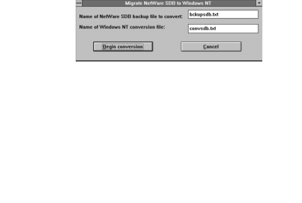
Migrating your Security Database
220 Installation Guide
The SDB backup file can be found in the "SYS:\SYSTEM\TSRV\SDB\BULK_ADD"
directory on your NetWare telephony server. You must put the file in the "\Program
Files\Telephony Services\tsrv\sdb\bulk_add" directory on your Windows NT, Windows
2000 or Windows XP telephony server.
Some changes need to be made to the data in your conversion file. MIGRATE.EXE makes
most of these changes for you.
MIGRATE.EXE:
Removes existing Tlink objects. New ones are added for you automatically when
you start up Telephony Services on your Windows NT, Windows 2000 or Windows
XP telephony server.
Removes the tserv object. Telephony Services for Windows NT, Windows 2000 or
Windows XP stores this information in the Registry, not the SDB.
Removes the NDS context (if present) from primary keys in each object record.
5. Run MIGRATE.EXE on your SDB backup file from the \Program
Files\Avaya\CT\tsrv\program directory on your Windows NT, Windows 2000 or
Windows XP machine.
The Migrate NetWare SDB to Windows NT dialog box appears. See Figure C-1.
Figure C-1: Migrate NetWare SDB to Windows NT Dialog Box
a. Enter the name of your conversion file and the name of the output file that is to be
created.
b. Click on "Begin conversion" to convert the data.
6. If the file already exists in the bulk_add directory, you are asked if you want to
overwrite the contents of the file. You cannot use the same name for both the backup
and conversion file.
7. Once you have completed the conversion step, you may choose to make some bulk
changes to your SDB data before you install it in your Windows NT, Windows 2000 or
Windows XP Telephony Services SDB.
a. Update Tlink Group and Admin Access Group Data.

Converting the Security Database
Issue 1 October 2003 221
●If your NetWare SDB contained Tlink groups or Admin Access Groups, these
group objects remain, but they will no longer contain any Tlinks. You will need to
add the new Tlink names to these groups.
●You may add Tlink members to your Tlink groups and Admin Access Groups by
editing the conversion file. However, it will probably be easier to make these
changes using the TSA or TSA32 applications after you have loaded the
conversion file into your SDB.
b. Convert IPX addresses to IP addresses.
●If you plan to use the "Extended Worktop Access" feature and you are migrating
from an IPX network to an IP network, you need to convert the network
addresses in each worktop record. You do not need to remove the IPX
information in the conversion file. You can let Telephony Services fill in the IP
Address or IP host name (depending on your choice in the "TCP Preferred
Naming Format" field).
●If you check the "Enable Automatic Administration of LAN Addresses" field
(available on the "Options" tab of the "Tserver Properties" dialog box in the
TSA32), Telephony Services will save the IP address/host name of each client
worktop when it opens its first connection to Telephony Services. In this case, no
further changes to the conversion file are required.
●If you are using the "Extended Worktop Access" feature but do not want to enable
the automatic LAN administration, you can either enter the IP address or host
name for each worktop in the conversion file, or you can make these changes
using the TSA32 applications after you have loaded the conversion file into your
SDB.
c. Enable system-level features:
Use the "Tserver Options" dialog box (available through "Admin" menu of the
TSA32) to set the following parameters:
●Extended Worktop Access — When this feature is enabled, the Telephony Server
checks the Security Database for a worktop with the same LAN address as the
workstation where the user is working. If a match is found, then the user is given
call control and device/device monitoring permissions for any of the devices
associated with that worktop.
Note:
Note: In NetWare Telephony Services, this feature is known as "Restrict User
Access to Home Worktop." Enabling the "Extended Worktop Access"
feature in Telephony Services running in Windows is equivalent to disabling
the "Restrict User Access to Home Worktop" feature in NetWare Telephony
Services.
●Enable Automatic Administration of LAN Addresses — If the LAN address is not
already assigned for the user’s worktop and you enable this feature, the Tserver
automatically fills in the LAN address information the next time the user logs on.

Migrating your Security Database
222 Installation Guide
(LAN addresses are only necessary if you are using the "Extended Worktop
Access" feature.)
8. Start Telephony Services on your Windows NT, Windows 2000 or Windows XP server
and bring up TSA32.
a. Select the "Bulk Admin" option from the "Admin" menu. This time, select the
"Upgrade SDB" option.
b. In the "Flat File Name" field, enter the name of the conversion file you created in
step 5. Click "OK."
Your SDB should now contain all the information that was previously on your
NetWare server.
Note:
Note: Telephony Services for Windows NT, Windows 2000 or Windows XP added
some SDB checking that was not implemented for NetWare Telephony
Services. These new checks could cause some records that were valid for
NetWare Telephony Services to be rejected for Telephony Services for
Windows NT, Windows 2000 or Windows XP. For example, the IP host
name and IP address for each workstation must be unique.
9. When the upgrade has completed, you should check the "errorsdb.txt" file, in the same
bulk_add directory for any errors that may have occurred during the conversion
process. See Chapter 11 of Avaya Computer Telephony 1.2, Telephony Services
Administration and Maintenance (NETMANGD.PDF) for information on resolving
these errors.

Issue 1 October 2003 223
Appendix D: Pre-Release 11 Link
Administration Instructions
The following instructions apply to a Release 10 or earlier switch.
Introduction
This appendix describes DEFINITY-based tasks that must be performed to implement
communications between the DEFINITY switch and the Avaya Computer Telephony
server.
Scope of this appendix
Refer to Figure D-1 as you read this section. The scope of this appendix includes the
DEFINITY switch and the communications interface to the Avaya CT server. The affected
components are as follows.
●The DEFINITY switch (DEFINITY ECS, DEFINITY PROLOGIX, or DEFINTY ONE)
●DEFINITY LAN Gateway (DLG) on either a Multi-Application Platform for DEFINITY
(MAPD) or a DEFINITY ONE.
Note:
Note: Hardware Platforms that accommodate the DLG software are:
-TN800 series MAPD, which is used in a DEFINITY ECS or DEFINITY
PROLOGIX.
-TN795 Processor Card (PROCR), which is used in the DEFINITY ONE. The
PROCR accommodates the DLG. Also, in some configurations, the TN795
card (with DLG resident) relies on the TN799 Control LAN (C-LAN) card for
LAN isolation.

Pre-Release 11 Link Administration Instructions
224 Installation Guide
Using the Information in this appendix
This appendix makes two basic assumptions — that you have a DEFINITY switch, with the
DEFINITY LAN Gateway (DLG) system already installed, and that you have a TCP/IP
based LAN that is capable of isolating your server-based functions from your client-based
functions.
The type of DEFINITY switch you have determines how you use this appendix.
●If you use a DEFINITY ECS or DEFINITY PROLOGIX, complete the tasks described in
"DEFINITY ECS and DEFINITY PROLOGIX Administration" on page -224.
●If you use a DEFINITY ONE, complete the tasks described in "DEFINITY ONE
Administration" on page -237.
DEFINITY ECS and DEFINITY
PROLOGIX Administration
This section describes DEFINITY ECS and DEFINITY PROLOGIX administrative tasks
you must complete before you can install Avaya CT (see Figure D-2 for an overview of the
tasks).
●Task 1: DEFINITY ECS and DEFINITY PROLOGIX Administration on a DEFINITY
System Administration Terminal (SAT)
●Task 2: MAPD and DLG Administration via a MAPD Administration Terminal
Once you complete these tasks, review the checklist at the end of this appendix and
proceed with Chapter 3: Installing Avaya Computer Telephony Server Software.
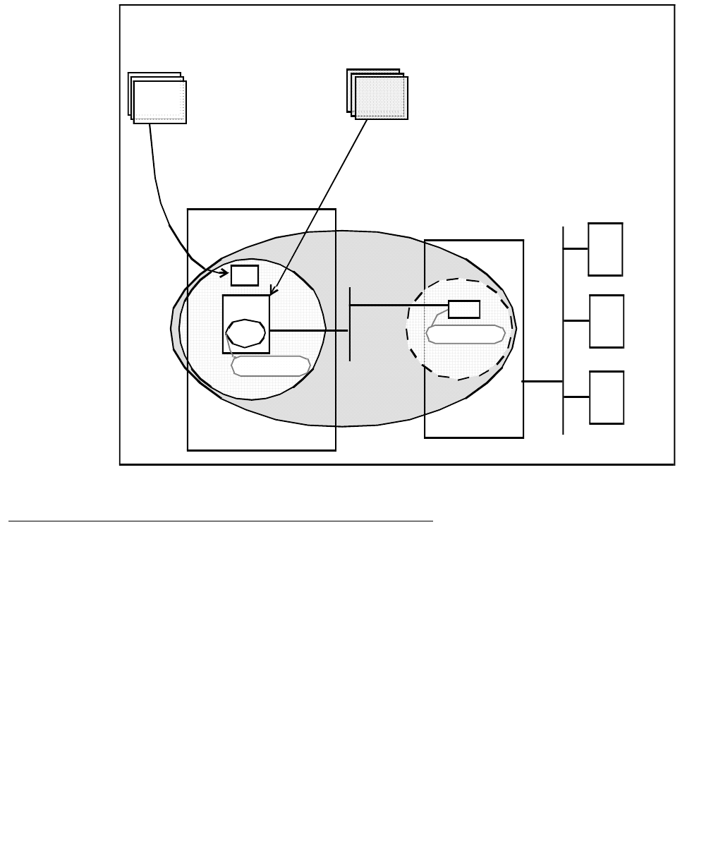
DEFINITY ECS and DEFINITY PROLOGIX Administration
Issue 1 October 2003 225
Figure D-1: DEFINTY ECS/DEFINITY PROLOGIX and MAPD/DLG Administration at a
Glance
DEFINITY ECS and DEFINITY PROLOGIX
Administration — Setting Up Your LAN for Avaya CT
Before you administer the DEFINITY switch (including the DLG), make sure that you have
determined how your LAN is set up.
Server LAN Segment (connectivity to the switch)
Server LAN segment functions are in the DLG administrative domain. For server-to-switch
functions follow these guidelines.
●The DLG must be connected to the LAN that the Avaya CT server uses (the Avaya CT
server communicates with the switch via the DEFINITY G3 PBX Driver).
DEFINITY ECS Avaya CT Server Clients
DEFINITY ECS and DEFINITY
PROLOGIX Administration DLG Administration
via MAPD Administration terminal
Verify software version
Verify ASAI features
List configuration
Administer station
Add a client — TCP/ IP ADMINISTRATION
Administer a link — PORT ADMINISTRATION
DLG ADMINISTRATIO N
Verify connectivity — DLG PORT/STATUS
LOCAL HOST TABLE
(MAPD in “ASAI” state)
Task 2
via SAT terminal
Task
1
CONTROL
NIC
MAPD
DLG 192.168.25.20
192. 168.2 5.10

Pre-Release 11 Link Administration Instructions
226 Installation Guide
●The DLG should be on its own separate LAN segment. To effect this, you will need two
Network Interface Cards (NICs) in the Avaya CT Server, one for client access and one
for the connection between the DLG and the DEFINITY G3 PBX Driver.
IP Addresses
It is strongly recommended that you use at least two IP addresses.
●IP address for the DLG.
Make certain that you have the IP address or the DLG or its host name (if host names
are used instead of IP addresses). See the DEFINITY switch administrator.
If you are using a separate LAN for your DLG (recommended) and all links go to a
single switch, then you can use the default IP address, which is 192.168.25.10.
●IP Address for the DEFINITY G3 PBX Driver,
Verify that you have a local IP address for the DEFINITY G3 PBX Driver on your
Telephony Server. You will need this IP address for installing the DEFINITY G3 PBX
Driver. You may obtain this address from the network administrator or you may use the
default address provided in the installation program (192.168.25.20) if you have a
private LAN (as recommended) between the Telephony Server and the DEFINITY
ECS switch. This local IP address should be different from the IP address used for the
Avaya CT server, as recommended.
Client LAN Segment
See Chapter 4: Installing Avaya Computer Telephony TSAPI Client Software for more
information about client-based Avaya CT requirements.
Guidelines for Setting Up a Private LAN
Follow these guidelines for implementing a private LAN for Avaya CT.
●Use IP addresses within the following ranges:
- 10.0.0.0 — 10.255.255.255
- 172.16.0.0 — 172.31.255.255
- 192.168.0.0 — 192.168.255.255
If You Intend to Use Host Names
You have the option of using host names, instead of IP addresses, when administering the
DEFINITY LAN Gateway and the DEFINITY G3 PBX Driver. If you use host names instead
of IP addresses, each entry in the HOSTS file provides information about one host on the
IP network. The DEFINITY LAN Gateway link connection is considered a host.
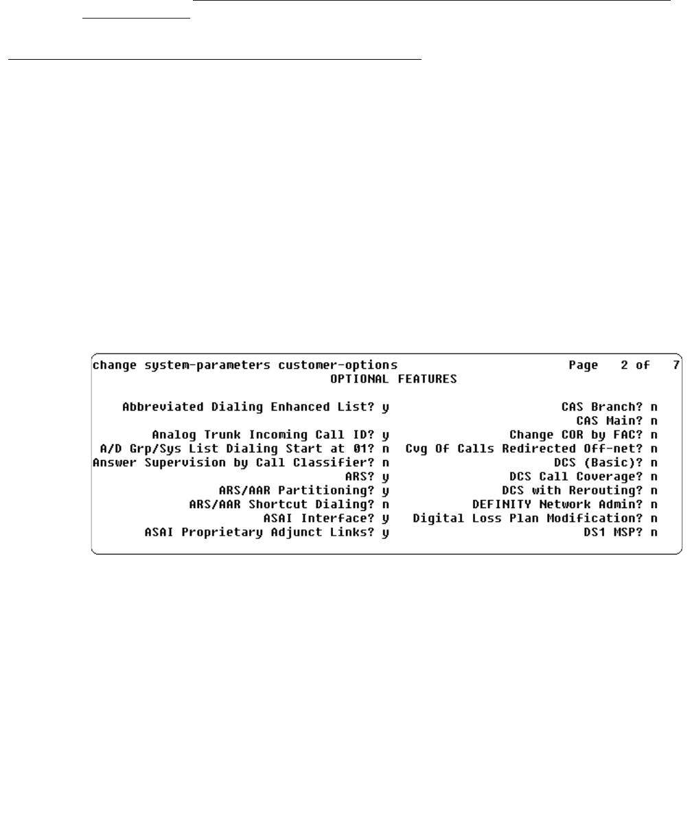
DEFINITY ECS and DEFINITY PROLOGIX Administration
Issue 1 October 2003 227
The DLG has a default set of administered parameters that correspond to the defaults
provided in the Avaya CT DEFINITY G3 PBX Driver installation. If you implement private
addressing you will have to change these settings on the G3PBX Driver Configuration
Dialog Box (see Procedure for Initial, Default Installation of Avaya Computer Telephony
Server Software, in Chapter 3.)
Task 1: DEFINITY ECS and
DEFINITY PROLOGIX — Administering a Link
The objective of Task 1 is administering a link. From the DEFINITY SAT, follow these steps
to complete Task 1.
Note:
Note: Whenever you use the change form of a DEFINITY SAT command, you
must log out for the changes to take effect.
1. Log in to the DEFINITY switch.
2. Type display system-parameters customer-options
The OPTIONAL FEATURES screen appears.
3. Check ASAI Proprietary Adjunct Links? and make sure it is set to y, (page 2
of the OPTIONAL FEATURES screen in the example above). This setting indicates
that DEFINITY is capable of communicating with an adjunct.
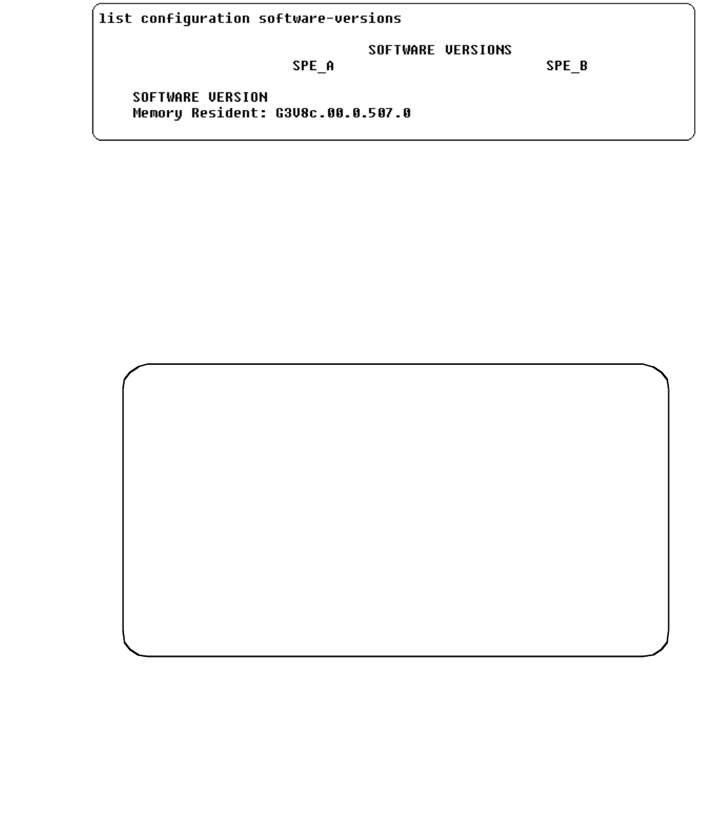
Pre-Release 11 Link Administration Instructions
228 Installation Guide
4. Type list configuration software-versions
The SOFTWARE VERSIONS screen appears.
5. Check the SOFTWARE VERSION to verify that the correct DEFINITY software version
is running on the switch. The following versions are appropriate: G3V4, or later.
Note:
Note: G3V4 requires a field maintenance release.
6. Type list config all to determine what ports are available on the MAPD for
adding a station.
The SYSTEM CONFIGURATION screen appears. Under Assigned Ports, each u
represents an available or unassigned port.
7. Choose a port associated with the MAPD board to add a station to the DLG (on the
MAPD).
8. Type add station
The STATION screen appears.
list configuration all
Page 1
----------------------------------------------------------------------
SYSTEM CONFIGURATION
Board
Number
1A01
1A02
1A03
1A04
1A05
1A06
Board T ype Co de V int age Ass igne d Por ts
EXPANSION INTF
EXPANSION INTF
RE SERV ED LG ATE
RE SERV ED LG ATE
MAPD BOARD
TN776
TN776
TN801
TN801
TN801
000001
000001
MAPD
MAPD
000001
u u u u u u u u
u u u u u u u u
01 u u u u u u u
u u u u u u u u
u u u u u u u u
u u u u u u u u

DEFINITY ECS and DEFINITY PROLOGIX Administration
Issue 1 October 2003 229
Note:
Note: For newer versions of the switch, the STATION screen may contain more
options. Only the options in Steps a through i are relevant to Avaya CT.
9. Follow Steps a through i to add an ASAI-enabled station. Completing the STATION
screen administers an adjunct IP link between DEFINITY and a Avaya CT server.
a. In the Extension: type any valid extension on the dial plan (for example, 1008).
b. In the Type: field, type ADJLK
c. In the Port: field, type an available port number
d. In the Name: field, type the name of the Avaya CT server
e. In the XID: field, accept the default (n)
f. In the Fixed TEI: field, type y
g. In the MIM Support: field, accept the default (n)
h. In the CRV Length: field, type 2
i. In the Event Minimization: field, accept the default (n)
All other fields on the Station screen use the default values.
This completes Task 1: DEFINITY Administration. Proceed to Task 2: DLG Administration.
STATION
Exten sion: 10 08
add s tatio n 1 008 Page 1 of 2 SPE A
----- ----- --- ------ --- ------ ----- --------- --------- ----- --- ------ --------- ---
----- ----- --- ------ --- ------ ----- --------- --------- ----- --- ------ --------- ---
Type: ADJLK___
Port: 1a0602_ __
Name: ________ ________ ____
TN: 1 __
COR: 1 _
COS: 1 _
STATI ON OPTIONS
BRI O PTION S
XID? n
MIM S upport? n
Fix ed TEI? y
CRV Le ngth: 2
Hunt-to Sta tion: _____
TEI: 1 _
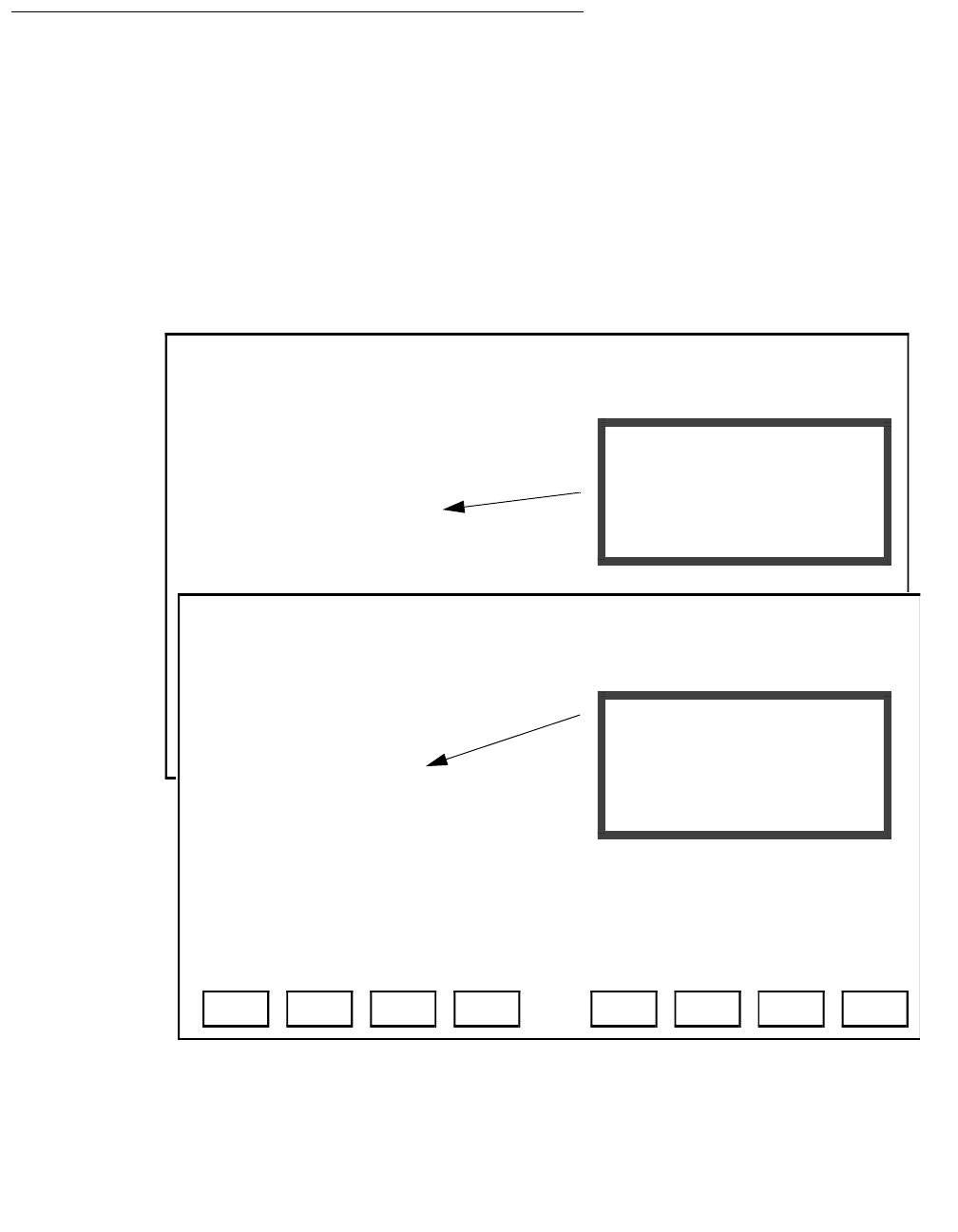
Pre-Release 11 Link Administration Instructions
230 Installation Guide
Task 2: DLG Administration
The objective of Task 2 is to establish connectivity between DEFINITY and your Avaya CT
server, by way of the DLG. Task 2 assumes that the DLG is already installed and
administered. For more information see DEFINITY ECS and CallVisor ASAI Applications
over MAPD (555-230-136).
From the MAPD administrative terminal, follow these steps to complete Task 2.
1. Log in to the MAPD system
The Main Menu appears.
2. From the Main Menu, select 2. TCP/IP Administration.
Main Menu
This line is used to provide abbreviated help on the currently selected field.
ENTEREXIT REFRESH HELP
1. Login/Password Administration
2. TCP/IP Administration...
3. Port Administration...
4. Maintenance...
5. DLG Port Status/Control
6. CV/LAN Port Status/Control
7. Exit Main Menu
This line is used to provide abbreviated help on the currently selected field.
ENTEREXIT REFRESH HELP
1. Login/Password Administration
2. TCP/IP Administration...
3. DLG Administration
4. Maintenance...
5. DLG Port Status/Control
6. Exit
If both the DLG and CVLAN
applications are on the MAPD
this Main Menu appears.
3. Port Administration... is
for access to DLG and CVLAN.
If only the DLG application
is on the MAPD
this Main Menu appears.
3.DLG Administration
for access to DLG.
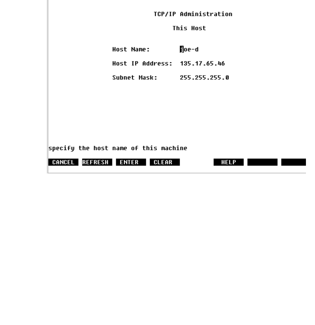
DEFINITY ECS and DEFINITY PROLOGIX Administration
Issue 1 October 2003 231
3. From the TCP/IP Administration screen select 1. This Host
The TCP/IP Administration This Host screen appears (This Host refers to the MAPD
itself).
4. Verify (or make a note of) the Host Name and IP address of the MAPD.
●The Host Name is the name that you assign to the MAPD.
●The Host IP Address is the IP address required when you perform G3 PBX Driver
link administration on the Avaya CT Server.
5. Once you have noted this information, select CANCEL to return to the Main Menu.
Pre-Release 11 Link Administration Instructions
232 Installation Guide
6. From the Main Menu, select 2. TCP/IP Administration.
The TCP/IP Administration screen appears.
7. From the TCP/IP Administration screen select 2. Local Host Table, which
enables you to view, add, or delete hosts. The host, in this case, is the Avaya CT
Server.
The TCP/IP Administration Local Host Table screen appears.
1. This Host
2. Local Host Table
3. Network Routing Information...
4. Exit
TCP/IP Administration
This line is used to provide abbreviated help on the currently selected field.
ENTE REXIT REFRESH HELP
DEFINITY ECS and DEFINITY PROLOGIX Administration
Issue 1 October 2003 233
Note:
Note: If the MAPD/DLG has already been administered to accept the default IP
address of the Avaya CT server (192.168.25.20), and you want to
implement a default Avaya CT configuration, skip Step 8a and 8b; go to Step
8c.
8. Follow Steps a through e to complete the Local Host Table
Note:
Note: The addressing information you use in steps 8a and 8b must be used (in the
DEFINITY G3PBX Driver dialog box) when you install Avaya CT.
a. In the IP Address field, type the
IP address of the G3PBX Driver on the Avaya CT server.
(You can accept the default 192.168.25.20 if you want to effect a "default" Avaya
CT installation.)
b. In the Host Name field, type the name that is assigned to the Avaya CT server.
c. Select ADD to save your settings.
d. Select CANCEL to return to the TCP/IP Administration Screen.
e. From the TCP/IP Administration Screen, select EXIT to return to the MAIN MENU.
TCP/IP Administration
___________________________________________________________________________
ADD DELETECANCEL REFRESH NXTPG PRVPGHELP
This line is used to provide abbreviated help on the currently selected field.
___________________________________________________________________________
___________________________________________________________________________
___________________________________________________________________________
___________________________________________________________________________
___________________________________________________________________________
___________________________________________________________________________
___________________________________________________________________________
Local Host Table
___________________________________________________________________________
___________________________________________________________________________
__________________________________________________________________
___________________________________________________________________________
___________________________________________________________________________
___________________________________________________________________________
___________________________________________________________________________
IP Address
X of X
Page
Host Name Aliases
Pre-Release 11 Link Administration Instructions
234 Installation Guide
9. From the Main Menu, select 3. Port Administration...
The Port Administration screen appears.
10. From the Port Administration screen, select 2. DLG Administration
The DLG Administration screen appears.
11. Follow steps a through c to complete the DLG Administration screen.
1. Application Port Assignment
2. DLG Administration
3. CV/LAN Administration
4. Exit
Port Administration
This line is used to provide abbreviated help on the currently selected field.
ENTE REXIT REFRESH HELP
DLG Administration
Client Name or IP Address
_________________________
Port
__
Client Link
__
ADD DELETECANCEL REFRESH UPDATEHELP
Client Status
___________
___________________________ __ ___________
___________________________ __ ___________
___________________________ __ ___________
___________________________ __ ___________
___________________________ __ ___________
___________________________ __ ___________
___________________________ __ ___________
This line is used to provide abbreviated help on the currently selected field.
DEFINITY ECS and DEFINITY PROLOGIX Administration
Issue 1 October 2003 235
a. In the Port field, type the port number of the DEFINITY station administered for the
link to the Avaya CT server (see Task 1, Step 8a)
b. In the Client Name or IP Address field, type the IP address or name assigned
to the G3PBX Driver on the Avaya CT server. This Client Name or IP Address refers
to the IP address you used in Step 8b.
(The default is 192.168.25.20).
c. In the Client Link field, type a number from 1 to 8 for the link assigned to the
Avaya CT server.
12. Return to the Main Menu, and from the Main Menu, select
5. DLG Port/Status Control.
The DLG Port/Status Control screen appears.
13. From the DLG Port Status/Control screen follow these steps.
a. Verify that the port number you administered in Step 11a appears under Port.
b. Verify that REACHABLE appears under TCP/IP Connection State.
This completes the DLG/MAPD administrative tasks.
See "Checklist — DEFINITY ECS and DEFINITY PROLOGIX" on page -236 to verify that
you have completed the DEFINITY and DLG/MAPD administrative tasks.
DEFINITY
Port
__________________________________________________________________
TCP/IP
MSGPERCANCEL REFRESH UPDATE DROPHELP STATE
This line is used to provide abbreviated help on the currently selected field.
Port
State Connection
State
DLG
Service
State
Messages
to
DEFINITY
Messages
from
DEFINITY
Message
Period
(minutes)
__________________________________________________________________
__________________________________________________________________
__________________________________________________________________
__________________________________________________________________
__________________________________________________________________
__________________________________________________________________
__________________________________________________________________

Pre-Release 11 Link Administration Instructions
236 Installation Guide
Checklist for DEFINITY ECS and
DEFINITY PROLOGIX with DLG/MAPD
— Before You Install Avaya CT
Use this checklist to make sure you have completed these tasks before you attempt to
install the Avaya CT software.
Table D-1: Checklist — DEFINITY ECS and DEFINITY PROLOGIX
Task Administrative
Interface See...
Verify that ASAI Proprietary
Adjunct Link option is installed
and enabled on the switch
(system-parameters customer-
options screen)
DEFINITY SAT Task 1, Step 2
Verify that the correct
DEFINITY software version is
running on the switch
DEFINITY SAT Task 1, Step 4
Determine what ports are
available for adding a station DEFINITY SAT Task 1, Step 6
Choose a port associated with
MAPD to add a station DEFINITY SAT Task 1, Step 7
Administer the Adjunct IP link. DEFINITY SAT Task 1, Step 8
Verify MAPD Host Name and
IP Address MAPD Terminal Task 2, Step 4
Add or verify Avaya CT IP
Address and Host Name MAPD Terminal Task 2, Step 8
Administer a Port, Client Name
(or IP Address) for the Avaya
CT Server
MAPD Terminal Task 2, Step 11
Verify that communications are
established between MAPD
and Avaya CT server
MAPD Terminal Task 2, Step 13
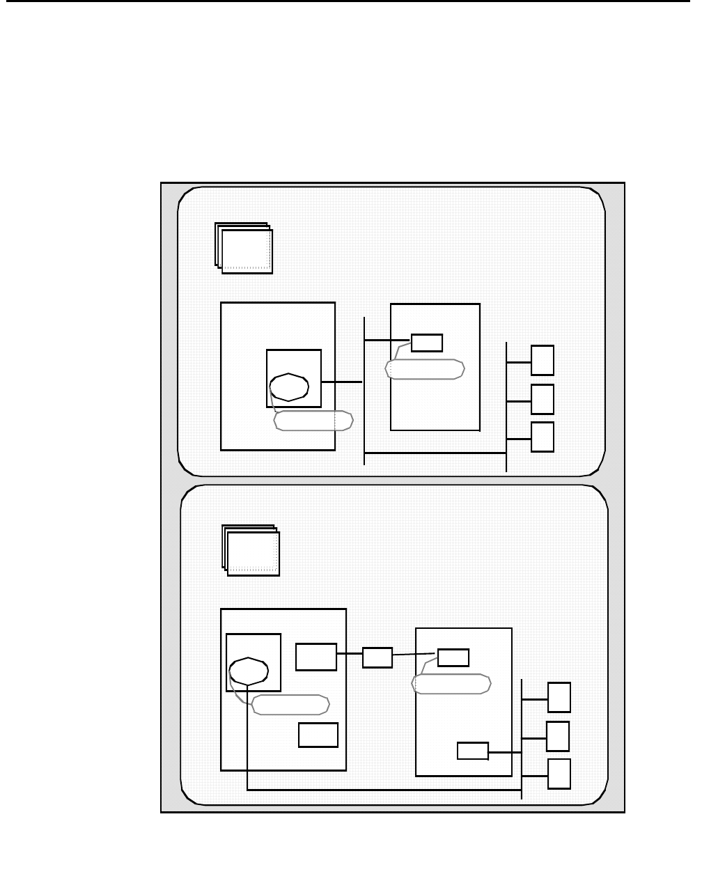
DEFINITY ONE Administration
Issue 1 October 2003 237
DEFINITY ONE Administration
DEFINITY ONE administrative tasks are done from the DEFINITY SAT (see Figure D-1).
DEFINITY ONE administration refers to administering DEFINTY for Avaya CT, as opposed
to DEFINTY site administration.
Figure D-2: DEFINTY ONE Administration at a Glance
DEFINITY ONE
Clients
DEFINITY ONE Administration via SAT
Clients
Verity ASAI features
Verify software version
Administer IP link endpoint
Administer DLG link on DEFINITY ONE
Define Avaya CT server name
Configuration Option 2 PROCR/DLG, C-LAN, and Data Module
Configuration Option 1 PROCR/DLG
PROCR
DLG
192.168.25.10
NIC
192.168.25.20
AvayaCT Server
DEFINITY ONE
PROCR
DLG
192.168. 25.10
Data
Module
C-LAN
NIC
NIC
192.168.25.20
HUB
Avaya CT Server
DEFINITY ONE Administration via SAT
Verity ASAI features
Verify software version
Administer IP link endpoint
Enab le PROCR coresident link
Administer DLG link on DEFINITY ONE
Define Avaya CT server name
Administer Data Module

Pre-Release 11 Link Administration Instructions
238 Installation Guide
DEFINITY ONE Pre-Administration
— Setting Up Your Avaya CT Configuration
Use this section to ensure that you know the requirements of your configuration before you
administer DEFINITY ONE for Avaya CT.
Basic Switch Requirements
These are the basic switch requirements.
●The CTI interface requires DEFINITY ONE R2, or later.
●The ASAI Proprietary Adjunct Link option must be enabled on the switch (system-
parameters customer-options screen).
Connectivity — Switch to Avaya CT Server
The DEFINITY ONE must be connected to the LAN that the DEFINITY G3 PBX Driver will
be using. Keep in mind that there are two basic configurations, which are described in the
next two sections.
Configuration Option 1: PROCR/DLG
If you do not require a separate, secure LAN segment for communications to DEFINITY
ONE and the telephony server, connectivity is established via the TN795 processor card
(PROCR) and the telephony server. In this arrangement, you will need only one NIC.
Configuration Option 2: PROCR/DLG, C-LAN and Data Module
If you require a separate, secure LAN connection from the G3PBX Driver to the DEFINITY
ONE, the telephony server will require its own separate LAN card. This means that you will
need two Network Interface Cards (NICs) in the Telephony Server, one for client access
and one for the connection between the DEFINITY ONE and the DEFINITY G3 PBX
Driver. Connectivity is established to DEFINITY ONE via the Control LAN (C-LAN) board
(TN799) and a Data Module.
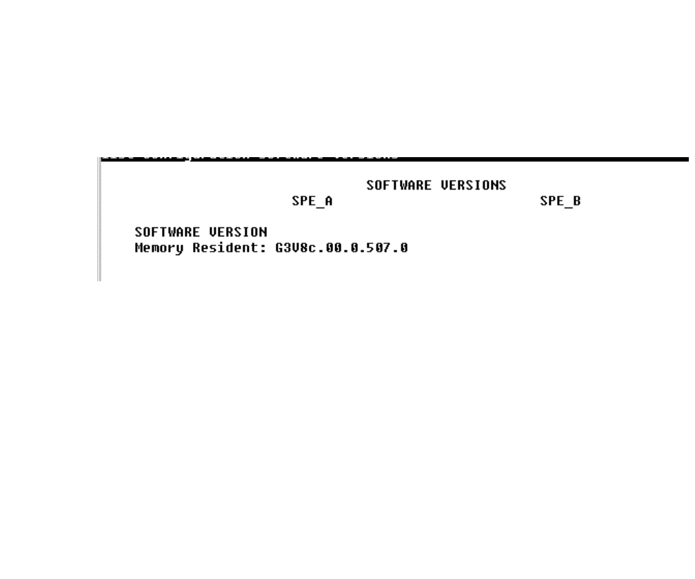
DEFINITY ONE Pre-Administration — Setting Up Your Avaya CT Configuration
Issue 1 October 2003 239
IP Address of DEFINITY G3 PBX Driver on
Avaya CT Server (Applies to Either Configuration
Option)
Verify that you have a local IP address for the DEFINITY G3 PBX Driver on your Telephony
Server. You will need this IP address for installing the DEFINITY G3 PBX Driver. You may
obtain this address from the Network Administrator or you may use the default address
provided in the installation program (192.168.25.20) if you have a private LAN (as
recommended) between the Telephony Server and the DEFINITY ONE. This local IP
address should be different from the IP address used for the G3PBX Driver on the Avaya
CT server.
Procedure for Setting Up TN795 PROCR
to DEFINITY ONE (Option 1)
If you are connecting to a DEFINITY via a PROCR running the DLG, follow this procedure.
Note:
Note: Whenever you use the change form of a DEFINITY ONE SAT command,
you must log out for the changes to take effect.
1. Log in to the DEFINITY ONE switch.
2. Type list configuration software-versions
The SOFTWARE VERSIONS screen appears.
3. Check the SOFTWARE VERSION, to ensure that the correct DEFINITY ONE software
version is running on the switch. The following version is appropriate: G3V8c, or later.
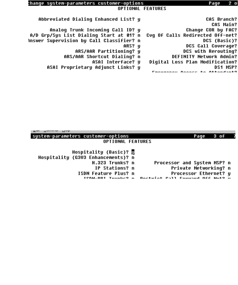
Pre-Release 11 Link Administration Instructions
240 Installation Guide
4. Type display system-parameters customer-options
The OPTIONAL FEATURES screen appears.
5. Check ASAI Proprietary Adjunct Links? and make sure it is set to y, (page 2
of the OPTIONAL FEATURES screen in the example above). If it is set to n, use the
change system-parameters customer-options command and set the
following feature:
ASAI Proprietary Adjunct Links? y
6. Type display system-parameters customer-options
The OPTIONAL FEATURES screen appears.
7. Check Processor Ethernet? and make sure it is set to y (page 3 of the
OPTIONAL FEATURES screen in the example above).
This setting enables the processor card coresident link. If it is set to n, use the change
system-parameters customer-options command and set the following
feature: ASAI Proprietary Adjunct Links? y
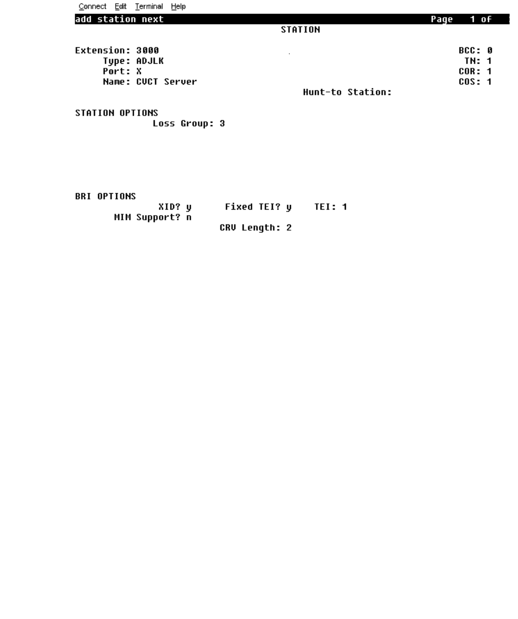
DEFINITY ONE Pre-Administration — Setting Up Your Avaya CT Configuration
Issue 1 October 2003 241
8. Type add station
The STATION screen appears.
9. Follow steps a through i to complete the STATION screen and administer the IP Link
endpoint.
a. In the Extension: field, type any valid extension on the dial plan (for example,
3000).
b. In the Type: field, type ADJLK
c. In the Port: field, type an available port number
d. In the Name: field, type the name of the Avaya CT server
e. In the XID: field, accept the default (n)
f. In the Fixed TEI: field, type y
g. In the MIM Support: field, accept the default (n)
h. In the CRV Length: field, type 2
i. In the Event Minimization: field, accept the default (n)
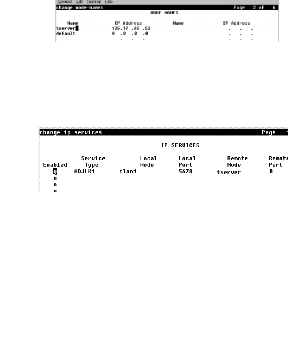
Pre-Release 11 Link Administration Instructions
242 Installation Guide
10. Type change node-names
The NODE NAMES screen appears.
11. Follow steps a and b to complete the NODE NAMES screen and define the Avaya CT
server’s name and address.
a. In the Name: field, type the name you want to assign to the Avaya CT server (free-
form field)
b. In the IP Address: field, type the IP address of the G3PBX Driver (default is
192.128.25.20)
12. Type change ip-services
The IP SERVICES screen appears.
13. Follow Steps a through e to complete the IP SERVICES screen and administer the
DLG link on a DEFINITY ONE system.
a. In the Service Type: field, type ADJLK1 (DEFINITY ONE uses link 1 only)
b. In the Local node-option: field, type procr
c. In the Local port: field, type 5678
d. In the Remote node: field, type the name you assigned to the Avaya CT server on
the NODE NAMES screen.
e. In the Remote port: field, type 0 (zero). Remote port is always set to zero.
This completes the procedure for setting up PROCR connectivity to DEFINITY ONE.
For a checklist of these administrative tasks, see Table D-2 on page -247.
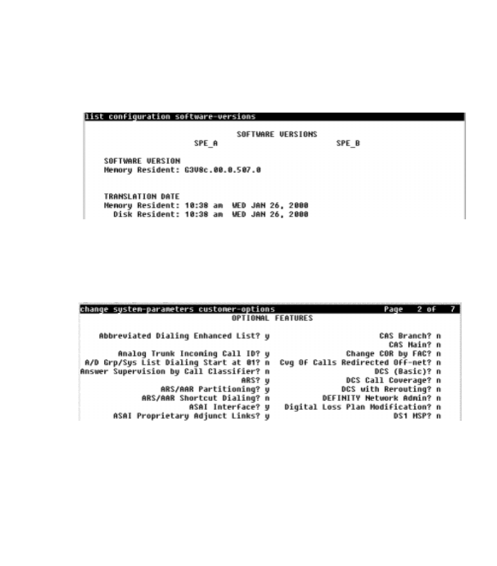
DEFINITY ONE Pre-Administration — Setting Up Your Avaya CT Configuration
Issue 1 October 2003 243
Procedure for Setting Up TN799 C-LAN
to DEFINITY ONE (Option 2)
If you are connecting to a DEFINITY via a C-LAN (running the DLG), a PROCR, and Data
Module follow this procedure.
Note:
Note: Whenever you use the change form of a DEFINITY ONE SAT command,
you must log out for the changes to take effect.
1. Log in to the DEFINITY ONE switch.
2. Type list configuration software-versions
The SOFTWARE VERSIONS screen appears.
3. Check the SOFTWARE VERSION, to ensure that the correct DEFINITY ONE software
version is running on the switch. The following version is appropriate: G3V8c, or later.
4. Type display system-parameters customer-options
The OPTIONAL FEATURES screen appears.
5. Check ASAI Proprietary Adjunct Links? and make sure it is set to y, (page 2
of the OPTIONAL FEATURES screen in the example above). If it is set to n, use the
change system-parameters customer-options command and set the
following feature:
ASAI Proprietary Adjunct Links? y
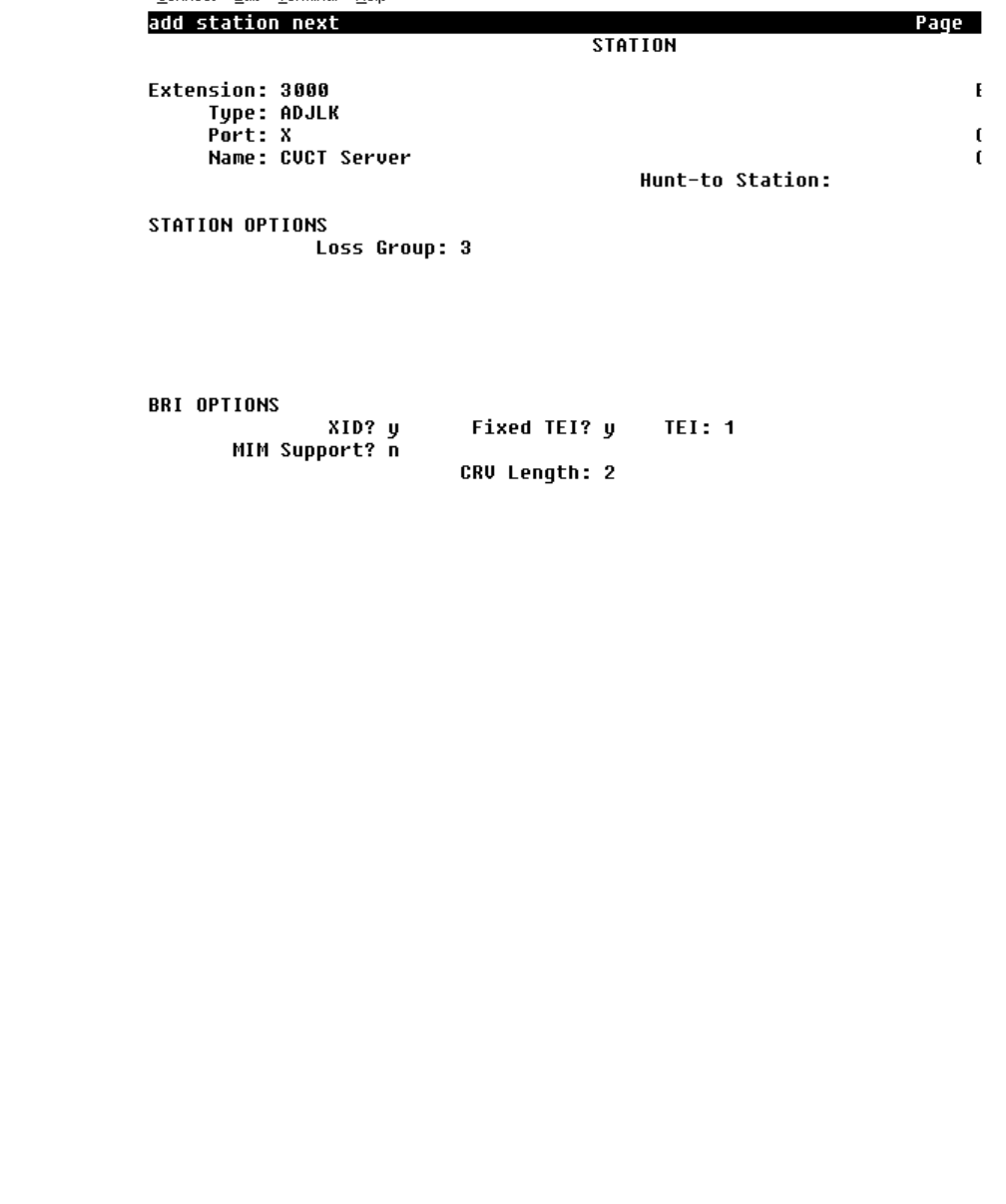
Pre-Release 11 Link Administration Instructions
244 Installation Guide
6. Type add station
The STATION screen appears.
7. Follow steps a through i to complete the STATION screen and administer the IP Link
endpoint.
a. In the Extension: field, type any valid extension on the dial plan (for example,
3000).
b. In the Type: field, type ADJLK
c. In the Port: field, type an available port number
d. In the Name: field, type the name of the Avaya CT server
e. In the XID: field, accept the default (n)
f. In the Fixed TEI: field, type y
g. In the MIM Support: field, accept the default (n)
h. In the CRV Length: field, type 2
i. In the Event Minimization: field, accept the default (n)
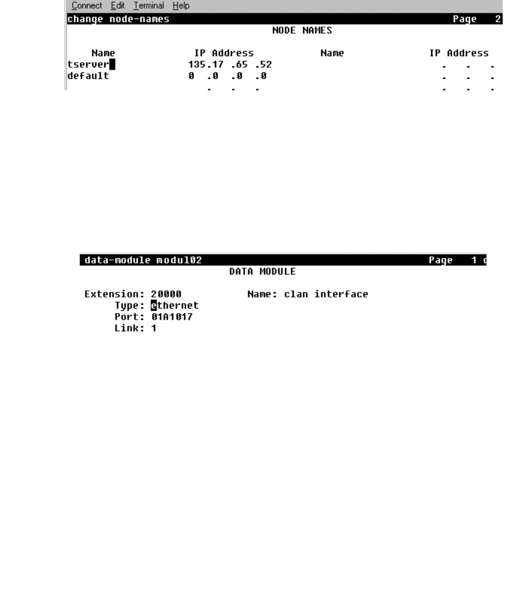
DEFINITY ONE Pre-Administration — Setting Up Your Avaya CT Configuration
Issue 1 October 2003 245
8. Type change node-names
The NODE NAMES screen appears.
9. Follow steps a and b to complete the NODE NAMES screen and define the Avaya CT
server’s name and address.
a. In the Name: field, type the name you want to assign to the Avaya CT server (free-
form field)
b. In the IP Address: field, type the IP address of the G3PBX Driver (default is
192.128.25.20)
10. Type add data-module modname (substitute modname with the name of your data
module. For example modul02).
The DATA MODULE screen appears.
11. Follow steps a through e to complete the DATA MODULE screen.
a. In the Data Extension: field, type any valid extension on the dial plan (for
example, 20000).
b. In the Type: field, type ethernet
c. In the Port: field, type 01A1017, where:
●01A10 is for the C-LAN board slot (in this example)
●017 is the port (must always be port 17)
d. In the Link: field, type any number from 1 to 25
e. In the Name: field, type the name you want to assign to the Avaya CT server (free-
form field)
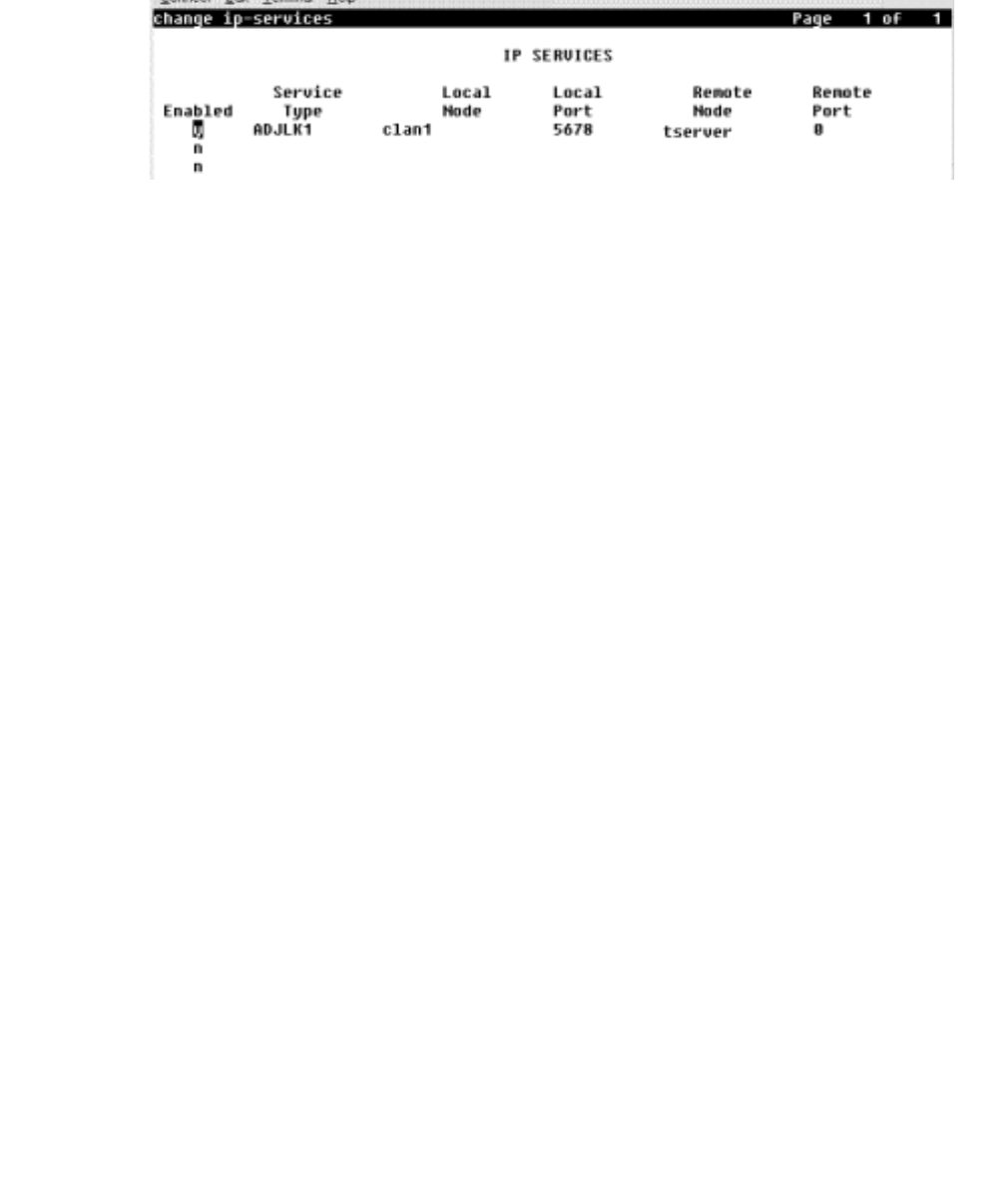
Pre-Release 11 Link Administration Instructions
246 Installation Guide
12. Type change ip-services
The IP SERVICES screen appears.
13. Follow steps a through e to complete the IP SERVICES screen, and administer the
DLG link as a DEFINITY ONE system.
a. In the Service Type: field, type ADJLK1 (DEFINITY ONE uses link 1 only)
b. In the Local node: field, type clan1
c. In the Local port: field, type 5678
d. In the Remote node: field type the name you assigned to the Avaya CT server in
Step 8a (NODE NAMES screen).
e. In the Remote port: field type 0 (zero). Remote port is always set to zero.
This completes the procedure for setting up C-LAN connectivity to DEFINITY ONE.
For a checklist of these administrative tasks, see Table D-3 on page -247.
Checklists for DEFINITY ONE
— Before You Install Avaya CT
The checklists in this section enable you to verify that you have completed the switch-
based tasks on DEFINITY ONE. Use the checklist that is appropriate for your
configuration.
●Checklist for DEFINITY ONE with TN795 PROCR (Option 1)
●Checklist for DEFINITY ONE withTN799 C-LAN (Option 2)
Checklist for DEFINITY ONE
with TN795 PROCR (Option 1)
If you have a DEFINITY one with a TN795 PROCR, make sure you have completed these
tasks before you install Avaya CT.

DEFINITY ONE Pre-Administration — Setting Up Your Avaya CT Configuration
Issue 1 October 2003 247
Table D-2: Checklist — DEFINITY ONE with TN795 PRCR — Option 1
Checklist for DEFINITY ONE
with TN799 C-LAN (Option 2)
If you implemented a configuration with DEFINITY ONE and a TN799 C-LAN, make sure
you have completed the tasks in the checklist below before you install Avaya CT.
Table D-3: Checklist — DEFINITY ONE with TN799 C-LAN — Option 2
Task See....
Verify that DEFINITY ECS
switch software supports the
CTI interface.
Steps 2 and 3 in "Procedure for
Setting Up PROCR Connectivity to
DEFINITY ONE"
Verify that ASAI Proprietary
Adjunct Link option is installed
and enabled on the switch
(system-parameters customer-
options screen).
Steps 4 and 5 in "Procedure for
Setting Up PROCR Connectivity to
DEFINITY ONE"
Verify that you have enabled
the PROCR coresident link. Step 6 and 7 in "Procedure for
Setting Up PROCR Connectivity to
DEFINITY ONE"
Administer the Adjunct IP link. Steps 8 and 9 in "Procedure for
Setting Up PROCR Connectivity to
DEFINITY ONE"
Define the Avaya CT server’s
name and address. Step 10 and 11 in "Procedure for
Setting Up PROCR Connectivity to
DEFINITY ONE"
Make sure that the DLG link is
administered on the DEFINITY
ONE system.
Steps 12 and 13 in "Procedure for
Setting Up PROCR Connectivity to
DEFINITY ONE"
Task See....
Verify that DEFINITY ECS
switch software supports the
CTI interface.
Steps 2 and 3 in "Procedure for
Setting Up C-LAN Connectivity to
DEFINITY ONE"
Verify that ASAI Proprietary
Adjunct Link option is installed
and enabled on the switch
(system-parameters customer-
options screen).
Steps 4 and 5 in "Procedure for
Setting Up C-LAN Connectivity to
DEFINITY ONE"
Administer the Adjunct IP link. Steps 6 and 7, in "Procedure for
Setting Up C-LAN Connectivity to
DEFINITY ONE"

Pre-Release 11 Link Administration Instructions
248 Installation Guide
Configuring DEFINITY ONE and Avaya CT
Figure depicts configuration settings on DEFINITY ONE and the Avaya CT Server
(DEFINITY G3 PBX Driver). The "DEFINITY G3PBX Driver IP Address" corresponds to the
IP address of the NIC on the Avaya CT server and the "Link... "IP Address or Hostname"
refers to the IP address of the DLG. The DLG IP address can be associated with either a
C-LAN (TN799) or a PROCR (TN795).
Define the Avaya CT server
name and IP address Steps 8 and 9 in "Procedure for
Setting Up C-LAN Connectivity to
DEFINITY ONE"
Make sure the Data Module has
been administered. Steps 10 and 11 in "Procedure for
Setting Up C-LAN Connectivity to
DEFINITY ONE"
Make sure the DLG link is
administered as a DEFINITY
ONE system.
Steps 12 and 13 in "Procedure for
Setting Up C-LAN Connectivity to
DEFINITY ONE"
Task See....
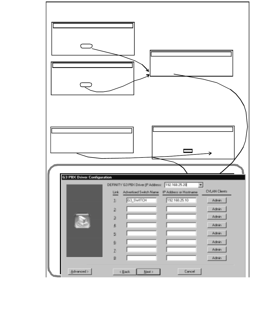
DEFINITY ONE Pre-Administration — Setting Up Your Avaya CT Configuration
Issue 1 October 2003 249
Figure D-3: DEFINITY ONE Administration v. Avaya CT Server Administration
Name
avayatsrv
NODE NAMES
IP AddressName . . .
stat us node- names
avayatsrv
Avaya CT Telephony Server Administration
DEFINITY ONE Administration
change ip-services
Enabl ed Service
Type
Local
Nod e Local
Port Remote
Node
Remote
Port
IP SERVIC ES
yclan
change ip-services
Enabl ed Service
Type Local
Nod e Local
Port Remot e
Node
Remote
Port
IP SERVIC ES
y
AD JLK
avayatsrv
To determine the IP address of “avayatsrv”
(the tel ephony server) use the
status node-names command. Local node
ADJLK 567 8
5678
0
0
is irrelevant in determining the IP
addr ess of “avayatsrv.”
On the IP SERVICES screen, Local Node is either “procr” or the name you assign to
the C-LAN (for example, avayatsrv).
IP Address
Name
avayatsrv
192.168.25.20
NODE NAMES
IP Address
Name . . .
stat us n ode- names
avayatsrv
change ip-services
Enabl ed Service
Type
Local
Nod e Local
Port Remot e
Node
Remot e
Port
IP SERVICES
yprocrADJLK 567 8 0
IP address of the C-LAN board or
the IP address of the PROCR board
for DEFINITY ONE.
avayatsrv
avayatsrv
IP address of the C-LAN board
or the IP address of he PROCR
board for DEFINITY ONE.
192.168.25.2
IP Address

Pre-Release 11 Link Administration Instructions
250 Installation Guide

Issue 1 October 2003 251
Index
Numerical
10Base-T Ethernet . . . . . . . . . . . . . . . . 215
32-bit client
installing
files copied to hard drive . . . . . . . . . . 200
verifying . . . . . . . . . . . . . . . . . . 109
uninstalling . . . . . . . . . . . . . . . 119, 146
A
add station command . . . . . . . . . . . . . . . 213
Adding tlink names . . . . . . . . . . . . . . . . 220
ADJLK feature, . . . . . . . . . . . . . . . 240, 243
Adjunct routing . . . . . . . . . . . . . . . . . . 126
Admin access groups . . . . . . . . . . . . . . . 220
Administration
brouter . . . . . . . . . . . . . . . . . . . . 215
for G3PD . . . . . . . . . . . . . . . . . . . 99
for MAPD . . . . . . . . . . . . . . . . . . . 215
for MFB . . . . . . . . . . . . . . . . . . . . 215
login/password . . . . . . . . . . . . . . . . . 215
maintenance . . . . . . . . . . . . . . . . . . 215
of DEFINITY switch . . . . . . . . . . . . . . 213
of LAN addresses . . . . . . . . . . . . . . . 221
port status control . . . . . . . . . . . . . . . 215
TCP/IP . . . . . . . . . . . . . . . . . . . . 215
Administration software
setting default account . . . . . . . . . . . . . 65
Telephony Services Administrator (TSA32) . 65, 99
Telephony Services Maintenance (TSM32) . 65, 99
user IDs . . . . . . . . . . . . . . . . . . . . 65
Alarm board. . . . . . . . . . . . . . . . . . . . 215
Applets. See Browser, running Java applets
ASAI Proprietary Adjunct Link Option (ADJLK) . . . 238
B
Basic Rate Interface . . . . . . . . . . . . . . . . 213
BRI ports. See Basic Rate Interface
BRI. See Basic Rate Interface
Brouter administration
for MFB or MAPD . . . . . . . . . . . . . . . 215
Brouter. See ISDN brouter
Browser, running Java applets . . . . . . . . . . . 157
Bulk administration feature . . . . . . . . . . . . 217
bulk_add directory . . . . . . . . . . . . . . . . 222
C
change station command . . . . . . . . . . . . . 213
Chapters, list of . . . . . . . . . . . . . . . . . . 12
Checking for errors . . . . . . . . . . . . . . . . 222
Checking link versions . . . . . . . . . . . . . . 126
CLAN (Control LAN) card . . . . . . . . . . . . . 238
client
software requirements. . . . . . . . . . . . . . 96
Client administration software. See Administration software,
client
Client platforms. See Platforms
Client software
description . . . . . . . . . . . . . . . . 98, 136
for administration . . . . . . . . . . . . . . . . 98
Clients
supported for CV/LAN server
Solaris SPARC . . . . . . . . . . . . . . 137
Solaris x86 . . . . . . . . . . . . . . . . 137
UnixWare . . . . . . . . . . . . . . . . . 137
Windows . . . . . . . . . . . . . . . . . 137
supported for Telephony Services
Java . . . . . . . . . . . . . . . . . . . . 35
UnixWare . . . . . . . . . . . . . . . . . . 35
Win32 . . . . . . . . . . . . . . . . . . . 35
Clients, multiple. See Multiple clients, setting up
Clients, setting up multiple clients . . . . . . . . . 108
Commands
add station . . . . . . . . . . . . . . . . . . 213
change station . . . . . . . . . . . . . . . . 213
Configuration settings, DEFINITY ONE and Avaya CT server
248
Connection to DEFINITY ONE, non-isolated LAN . 238
Conversion file, SDB . . . . . . . . . . . . . . . 218
Converting IPX addresses . . . . . . . . . . . . 221
Converting SDB to NT format . . . . . . . . . . . 218
Creating flat file, from SDB . . . . . . . . . . . . 218
CTI links
settings . . . . . . . . . . . . . . . . . . . 214
station administration . . . . . . . . . . . . . 214
Customer support
for DEFINITY G3 PBX Driver . . . . . . . . . . 21
for Telephony Services . . . . . . . . . . . . . 21

252 Installation Guide
for Tserver operation . . . . . . . . . . . . . . 21
CV/LAN client
hardware requirements . . . . . . . . . . . . 136
installing on Solaris SPARC . . . . . . . . . . 141
installing on UnixWare . . . . . . . . . . . . 144
installing on Windows NT . . . . . . . . . . . 138
platform . . . . . . . . . . . . . . . . . . . 137
software requirements. . . . . . . . . . . . . 136
supported platforms. . . . . . . . . . . . . . 137
uninstalling on Solaris SPARC. . . . . . . . . 147
uninstalling on Windows NT . . . . . . . . . . 146
CV/LAN server
handling routing requests . . . . . . . . . . . 126
link sharing . . . . . . . . . . . . . . . . . . 126
manually stopping. . . . . . . . . . . . . . . . 89
need for load balancing . . . . . . . . . . . . 126
post-installation tasks . . . . . . . . . . . . . . 87
reinstalling . . . . . . . . . . . . . . . . . . . 90
CVLAN client, adding. . . . . . . . . . . . . . . 128
CVLAN client, IP address . . . . . . . . . . . . . 129
CVLAN server . . . . . . . . . . . . . . . . . . 125
D
Default account, for administration software. See
Administration software, setting default account
DEFINITY G3 PBX Driver Administrator Utility. See G3PD
OA&M utility
DEFINITY G3 private data support libraries. See Private
data support libraries
DEFINITY G3 switch administration . . . . . . . . 213
DEFINITY LAN Gateway
description . . . . . . . . . . . . . . . . . . 215
settings for connections . . . . . . . . . . . . 214
DEFINITY Multi-function board. See Multi-function board
DLG. See DEFINITY LAN Gateway
Document organization . . . . . . . . . . . . . . . 12
E
Editing Tslibrc file . . . . . . . . . . . . . . . . .118
Error log file . . . . . . . . . . . . . . . . . . . . 91
Errors, after conversion to NT . . . . . . . . . . . 222
errorsdb.txt file . . . . . . . . . . . . . . . . . . 222
Extended worktop access feature . . . . . . . . . 221
F
Files
error log . . . . . . . . . . . . . . . . . . . . 91
errorsdb.txt . . . . . . . . . . . . . . . . . . 222
LTJTAPI.CAB . . . . . . . . . . . . . . . . 150
LTJTAPI.JAR . . . . . . . . . . . . . . . . . 150
LTJTAPI.ZIP . . . . . . . . . . . . . . . . . 149
LTJTAPIA.CAB . . . . . . . . . . . . . . . . 150
LTJTAPIA.JAR . . . . . . . . . . . . . . . . 150
LTJTAPIA.ZIP. . . . . . . . . . . . . . . . . 150
message trace . . . . . . . . . . . . . . . . . 91
SDB log. . . . . . . . . . . . . . . . . . . . . 91
TSAPI.PRO . . . . . . . . . . . . . . . . . . 157
Flat file, creating
using NWAdmin . . . . . . . . . . . . . . . . 218
using TSA. . . . . . . . . . . . . . . . . . . 218
G
G3 PBX Driver Configuration Utility . . . . . . . . . 68
G3 PBX Link Change Utility . . . . . . . . . . . . . 68
G3PD
administrator utility. . . . . . . . . . . . . . . . 99
configuration parameter defaults . . . . . . . . . 82
default directory . . . . . . . . . . . . . . . . . 81
IP address . . . . . . . . . . . . . . . . . . . 82
OA&M utility. . . . . . . . . . . . . . . . . . . 99
H
Handling routing requests . . . . . . . . . . . . . 126
Hardware requirements
for CV/LAN clients . . . . . . . . . . . . . . . 136
for Java clients . . . . . . . . . . . . . . . . 168
for UnixWare clients . . . . . . . . . . . . . . . 97
for Windows-based clients . . . . . . . . . . . . 96
HP-UX
installing the SDK . . . . . . . . . . . . . . . 185
HP-UX Client
Installing . . . . . . . . . . . . . . . . . . . 116
Removing . . . . . . . . . . . . . . . . . . . 120
HP-UX client, installing . . . . . . . . . . . . . . 116
I
Installation
tasks following. . . . . . . . . . . . . . . . . . 87
verifying
Solaris SPARC client . . . . . . . . . .111, 142
UnixWare client . . . . . . . . . . . . . . 146
Win32 client . . . . . . . . . . . . . . . . 109
Windows NT client . . . . . . . . . . . . . 141
Installing
32-bit client
files copied to hard drive . . . . . . . . . . 200
verifying . . . . . . . . . . . . . . . . . . 109
client software, overview . . . . . . . . . . . . 122

Issue 1 October 2003 253
client software, preliminary . . . . . . . . . . . 101
CV/LAN client
on Solaris SPARC . . . . . . . . . . . . . 141
on Windows NT. . . . . . . . . . . . . . . 138
on CV/LAN
UnixWare client. . . . . . . . . . . . . . . 144
Solaris SPARC client
verifying . . . . . . . . . . . . . . . 111, 142
UnixWare client
files copied to hard drive . . . . . . . . . . 201
from command line . . . . . . . . . . . . . 112
from diskettes . . . . . . . . . . . . . . . 114
from the CD . . . . . . . . . . . . . 112, 144
verifying . . . . . . . . . . . . . . . . . . 146
Windows NT client
verifying . . . . . . . . . . . . . . . . . . 141
Internet Explorer. . . . . . . . . . . . . . . . . . 35
Internet Explorer, running Java applets . . . . . . . 158
Invalid records, on NT . . . . . . . . . . . . . . . 222
IP address
converting . . . . . . . . . . . . . . . . . . . 221
G3PD . . . . . . . . . . . . . . . . . . . . . 82
IP address, DEFINITY G3 PBX Driver . . . . . . . 82
IP forwarding. See IP routing
IP routing . . . . . . . . . . . . . . . . . . . . . 31
IPX address, converting . . . . . . . . . . . . . . 221
ISDN brouter . . . . . . . . . . . . . . . . . . . 215
J
Java client
Avaya CT implementation interfaces. . . . . . . 149
concern about download time . . . . . . . . . . 149
default port number. . . . . . . . . . . . . . . 157
hardware requirements . . . . . . . . . . . . . 168
JavaSoft interface . . . . . . . . . . . . . . . 149
private data versions . . . . . . . . . . . . . . 35
running applets in browser . . . . . . . . . . . 157
set 1. . . . . . . . . . . . . . . . . . . . . . 149
set 2. . . . . . . . . . . . . . . . . . . . . . 149
software requirements . . . . . . . . . . . . . 168
supported for Telephony Services . . . . . . . . 35
supported operating systems . . . . . . . . . . 35
Java Virtual Machine
supported version . . . . . . . . . . . . . . . 157
L
LAN port . . . . . . . . . . . . . . . . . . . . . 215
License disk. . . . . . . . . . . . . . . . . . . . 78
Link settings. See CTI links, settings
Links
sharing. . . . . . . . . . . . . . . . . . . . 126
versions . . . . . . . . . . . . . . . . . . . 126
Load balancing. . . . . . . . . . . . . . . . . . 126
Login/password administration
for MFB or MAPD . . . . . . . . . . . . . . . 215
LTJTAPI.CAB file . . . . . . . . . . . . . . . . 150
LTJTAPI.JAR file. . . . . . . . . . . . . . . . . 150
LTJTAPI.ZIP file . . . . . . . . . . . . . . . 149, 150
LTJTAPIA.CAB file . . . . . . . . . . . . . . . . 150
LTJTAPIA.JAR file . . . . . . . . . . . . . . . . 150
M
Maintenance administration
for MFB or MAPD . . . . . . . . . . . . . . . 215
Manually stopping
CV/LAN server . . . . . . . . . . . . . . . . . 89
Telephony Services . . . . . . . . . . . . . . . 89
MAPD. See Multi-application for DEFINITY board
Message trace file . . . . . . . . . . . . . . . . . 91
MFB. See Multi-function board
MIGRATE.EXE, functions of . . . . . . . . . . . 220
Multi-application for DEFINITY board . . . . . . . 215
Multi-function board . . . . . . . . . . . . . . . 215
N
Netscape Communicator, running Java applets . . 158
Netscape Navigator . . . . . . . . . . . . . . . . 35
NetWare
security database . . . . . . . . . . . . . . . 218
server, migrating from . . . . . . . . . . . . . 217
Network addresses. . . . . . . . . . . . . . . . 221
Network interface card
for connections . . . . . . . . . . . . . . . . . 31
IP address . . . . . . . . . . . . . . . . . . . 82
O
Organization, of document . . . . . . . . . . . . . 12
P
Platforms
CV/LAN client . . . . . . . . . . . . . . . . 137
Telephony Services client . . . . . . . . . . . . 98
UnixWare . . . . . . . . . . . . . . . . . . . 98
Port status control administration
for MFB or MAPD . . . . . . . . . . . . . . . 215
Private data support libraries . . . . . . . . . . . . 98
Private data versions
for Java clients . . . . . . . . . . . . . . . . . 35

254 Installation Guide
for UnixWare clients. . . . . . . . . . . . . . . 35
for Win32 clients . . . . . . . . . . . . . . . . 35
Processor card (PROCR), TN795 . . . . . . . . . 238
R
Reinstalling
CV/LAN server . . . . . . . . . . . . . . . . . 90
Telephony Services . . . . . . . . . . . . . . . 90
Requirements
hardware for CV/LAN clients. . . . . . . . . . 136
hardware for Java clients . . . . . . . . . . . 168
hardware for UnixWare clients . . . . . . . . . . 97
hardware for Windows-based clients . . . . . . . 96
software for CV/LAN clients . . . . . . . . . . 136
software for Java clients. . . . . . . . . . . . 168
software for UnixWare clients . . . . . . . . . . 97
software for Windows-based clients . . . . . . . 96
Restrict user access to home worktop. See Extended
worktop access
Routing requests . . . . . . . . . . . . . . . . . 126
RS-232 console (serial) port . . . . . . . . . . . 215
S
SCO UnixWare client
supported operating systems . . . . . . . . . 137
SDB log file . . . . . . . . . . . . . . . . . . . . 91
SDB. See Security database
Secure connection to DEFINITY one . . . . . . . 238
Security checklist, DEFINITY ONE . . . . . . . . . 33
Security database
conversion file . . . . . . . . . . . . . . . . 218
converting to NT format . . . . . . . . . . . . 218
NetWare . . . . . . . . . . . . . . . . . . . 218
Serial port . . . . . . . . . . . . . . . . . . . . 215
Set 1, Java client. . . . . . . . . . . . . . . . . 149
Set 2, Java client. . . . . . . . . . . . . . . . . 149
Software requirements
for CV/LAN clients . . . . . . . . . . . . . . 136
for Java clients . . . . . . . . . . . . . . . . 168
for UnixWare clients. . . . . . . . . . . . . . . 97
for Windows-based clients. . . . . . . . . . . . 96
Solaris SPARC client
installing
verifying . . . . . . . . . . . . . . . 111, 142
installing on CV/LAN server . . . . . . . . . . 141
supported operating systems . . . . . . . . . 137
uninstalling from CV/LAN server . . . . . . . . 147
Solaris x86 client
CV/LAN server version . . . . . . . . . . . . 137
Spreadsheet, for viewing SDB . . . . . . . . . . 217
Stopping, manually . . . . . . . . . . . . . . . . . 89
Support for customers. . . . . . . . . . . . . . . . 21
Switch administration . . . . . . . . . . . . . . . 213
System-level features, enabling . . . . . . . . . . 221
T
TCP/IP administration
for MFB or MAPD . . . . . . . . . . . . . . . 215
TCP/IP transport type, UnixWare client. . . . . . . 113
Telephony Services
client platforms . . . . . . . . . . . . . . . . . 98
installing client software . . . . . . . . . 101, 122
installing HP-UX client . . . . . . . . . . . . . 116
manually stopping . . . . . . . . . . . . . . . . 89
post-installation tasks . . . . . . . . . . . . . . 87
reinstalling . . . . . . . . . . . . . . . . . . . 90
uninstalling 32-bit client . . . . . . . . . .119, 146
uninstalling HP-UX client. . . . . . . . . . . . 120
uninstalling UnixWare client . . . . . . . .119, 120
Telephony Services Security Database. See Security
database
Tlink
groups . . . . . . . . . . . . . . . . . . . . 220
names . . . . . . . . . . . . . . . . . . . . 220
TN795 processor card. . . . . . . . . . . . . . . 238
Toll fraud. . . . . . . . . . . . . . . . . . . . . . 32
TSA32. See Administration software
TSAPI Solaris client, installing . . . . . . . . . . . 110
TSAPI.PRO file . . . . . . . . . . . . . . . . . . 157
tslib.ini (Windows clients) . . . . . . . . . . . . . 106
TSLIB.INI file (setup information). . . . . . . . . . 106
tslibrc (editing) . . . . . . . . . . . . . . . . . . 118
tslibrc (HP-UX, Solaris, and UnixWare clients) . . . 118
tslibrc (TSAPI Solaris client) . . . . . . . . . . . . 110
TSM32. See Administration software.
U
Uninstalling
32-bit client . . . . . . . . . . . . . . . .119, 146
CV/LAN client
on Solaris SPARC . . . . . . . . . . . . . 147
on Windows NT . . . . . . . . . . . . . . 146
UnixWare client . . . . . . . . . . . . . .119, 120
UnixWare client
hardware requirements . . . . . . . . . . . . . 97
installing
files copied to hard drive . . . . . . . . . . 201
from diskettes . . . . . . . . . . . . . . . 114
from the CD . . . . . . . . . . . . . .112, 144
verifying . . . . . . . . . . . . . . . . . . 146

Issue 1 October 2003 255
installing on CV/LAN server . . . . . . . . . . . 144
platform . . . . . . . . . . . . . . . . . . . . 98
private data versions . . . . . . . . . . . . . . 35
software requirements . . . . . . . . . . . . . 97
supported for CV/LAN server . . . . . . . . . . 137
supported for Telephony Services . . . . . . . . 35
supported server versions . . . . . . . . . . . 137
uninstalling . . . . . . . . . . . . . . . 119, 120
UnixWare client, installing . . . . . . . . . . . . . 112
Updating
admin access groups . . . . . . . . . . . . . . 220
tlink groups . . . . . . . . . . . . . . . . . . 220
User IDs, for administrative software . . . . . . . . 65
V
Verifying installation
of Solaris SPARC client. . . . . . . . . . 111, 142
of UnixWare client . . . . . . . . . . . . . . . 146
of Win32 client . . . . . . . . . . . . . . . . . 109
of Windows NT client . . . . . . . . . . . . . . 141
W
Web site
download time for Java client . . . . . . . . . . 149
Win32 client
hardware requirements . . . . . . . . . . . . . 96
installing
files copied to hard drive . . . . . . . . . . 200
verifying . . . . . . . . . . . . . . . . . . 109
private data versions . . . . . . . . . . . . . . 35
software requirements . . . . . . . . . . . . . 96
supported for Telephony Services . . . . . . . . 35
uninstalling . . . . . . . . . . . . . . . 119, 146
Windows NT
converting SDB to . . . . . . . . . . . . . . . 218
installing CV/LAN client . . . . . . . . . . . . . 138
registry . . . . . . . . . . . . . . . . . . . . 90
server, migrating to. . . . . . . . . . . . . . . 217
uninstalling CV/LAN client . . . . . . . . . . . 146
Windows NT client
installing
verifying . . . . . . . . . . . . . . . . . . 141
supported for CV/LAN server . . . . . . . . . . 137
supported operating systems . . . . . . . . . . 137
supported server versions . . . . . . . . . . . 137
Workstations. See Platforms
Worktop access feature. See Extended worktop access
feature

256 Installation Guide
