Avaya Bcm200 400 Installation And Maintenance Manual
2015-06-01
: Avaya Avaya-Bcm200-400-Installation-And-Maintenance-Manual-735690 avaya-bcm200-400-installation-and-maintenance-manual-735690 avaya pdf
Open the PDF directly: View PDF ![]() .
.
Page Count: 374 [warning: Documents this large are best viewed by clicking the View PDF Link!]
- North American Regulatory Information
- Safety
- Enhanced 911 Configuration
- Radio-frequency Interference
- Telecommunication Registration
- Network Connection
- Hearing Aid Compatibility
- Electromagnetic Compatibility
- Telephone Company Registration
- Use of a Music Source
- Rights of the Telecommunications Company
- Repairs
- Canadian Regulations - please read carefully
- US Regulations - please read carefully
- International Regulatory Information
- Limited Warranty
- Preface
- Introduction to the Business Communications Manager Platform Hardware
- Business Communications Manager Field Replaceable Units
- BCM200 Platform Base Hardware
- BCM400 Platform Base Hardware
- Platform Media Bay Module Bays and Backplane
- Base Function Tray Component Hardware
- I/O Interface card
- Platform Power Supply
- Hard Disk
- Cooling Fan
- Telephony Components
- Telephones and adapters
- Business Communications Manager Expansion Unit
- Auxilliary Requirements and Installation Process Overview
- Install the Business Communications Manager & Expansion Unit Platform Base Chassis
- Install, remove or replace the Media Bay Modules
- Business Communications Manager System Startup
- Prepare Hardware for Maintenance or Upgrades
- Hard Disk Replacement Procedures
- Install or Replace a Cooling Fan
- Replace or Upgrade a Power Supply
- Replace Data Cards and Processing Hardware
- Install Telephones and Peripherals
- Install Companion or DECT Systems
- The Companion Wireless System
- Companion Hardware Installation
- Install DECT Systems
- Install Analog Terminal Adapters
- Install Optional Telephony Equipment
- Troubleshooting
- System Region Attributes
- Telephony Hardware Selection and Settings
- Media Bay Module System Selection
- Set Media Bay Module Dip Switches
- Rules for Assigning DS30 Resources
- Determine module DIP switch settings
- Set the media bay module DIP switches
- Line and extension numbers for specific modules
- Media Bay Module Combinations
- System Options
- Glossary

Part No. P0993133 03
Business Communications
Manager
BCM200/400
Installation and Maintenance
Guide

2
P0993133 03
Copyright © 2002 Nortel Networks
All rights reserved. November, 2002.
The information in this document is subject to change without notice. The statements, configurations, technical data, and
recommendations in this document are believed to be accurate and reliable, but are presented without express or implied
warranty. Users must take full responsibility for their applications of any products specified in this document. The
information in this document is proprietary to Nortel Networks NA Inc.
Trademarks
NORTEL NETWORKS and Business Communications Manager, are trademarks of Nortel Networks NA Inc.
Microsoft, MS, MS-DOS, Windows, and Windows NT are registered trademarks of Microsoft Corporation.
Symbol, Spectrum24, and NetVision are registered trademarks of Symbol Technologies, Inc.
All other trademarks and registered trademarks are the property of their respective owners.
North American Regulatory Information
Safety
Business Communications Manager equipment meets all applicable requirements of both the CSA
C22.2 No. 950-95 and UL-1950 Edition 3.
Danger: Risk of shock.
Read and follow installation instructions carefully.
Ensure the Business Communications Manager and Business Communications Manager
expansion unit are unplugged from the power socket and that any telephone or network
cables are unplugged before opening the Business Communications Manager or Business
Communications Manager expansion unit.
If installation of additional hardware and /or servicing is required, disconnect all telephone
cable connections prior to unplugging the Business Communications Manager.
Ensure the Business Communications Manager and Business Communications Manager
expansion unit are plugged into the wall socket using a three-prong power cable before
any telephone cables are connected.
3
Installation and Maintenance Guide
Enhanced 911 Configuration
Radio-frequency Interference
Caution: Only qualified persons should service the system.
The installation and service of this hardware is to be performed only by service personnel
having appropriate training and experience necessary to be aware of hazards to which they
are exposed in performing a task and of measures to minimize the danger to themselves or
other persons.
Electrical shock hazards from the telecommunication network and AC mains are possible
with this equipment. To minimize risk to service personnel and users, the Business
Communications Manager system must be connected to an outlet with a third-wire ground.
Service personnel must be alert to the possibility of high leakage currents becoming
available on metal system surfaces during power line fault events near network lines. These
leakage currents normally safely flow to Protective Earth ground via the power cord.
Therefore, it is mandatory that connection to an earthed outlet is performed first and
removed last when cabling to the unit. Specifically, operations requiring the unit to be
powered down must have the network connections (central office lines) removed first.
Caution: Warning
Local, state and federal requirements for Emergency 911 services support by Customer
Premises Equipment vary. Consult your telecommunication service provider regarding
compliance with applicable laws and regulations.
Note: For information about 911 configuration, refer to the Enhanced 911 (E911)
Configuration section in the Business Communications Manager 3.0 Programming
Operations Guide.
Warning: Equipment generates RF energy.
This equipment generates, uses, and can radiate radio-frequency energy. If not installed
and used in accordance with the installation manual, it may cause interference to radio
communications. It has been tested and found to comply with the limits for a Class A
computing device pursuant to Part 15 of the FCC Rules and with ICES.003, CLASS A
Canadian EMI Requirements. Operation of this equipment in a residential area is likely to
cause interference, in which case the user, at his or her own expense, will be required to
take whatever measures may be required to correct the interference.
4
P0993133 03
Telecommunication Registration
Business Communications Manager equipment meets all applicable requirements of both Industry
Canada CS-03 and US Federal Commission FCC Part 68 and has been registered under files
Industry Canada 332D-5980A and FCC US:AB6KF15B20705 (key system),
US:AB6MF15B20706 (hybrid system), and US:AB6PF15B23740 (PBX system). Connection of
the Business Communications Manager telephone system to the nationwide telecommunications
network is made through a standard network interface jack that you can order from your local
telecommunications company. This type of customer-provided equipment cannot be used on party
lines or coin lines.
Before installing this equipment, users should ensure that it is permissible to be connected to the
facilities of the local telecommunications company. The equipment must also be installed using an
acceptable method of connection. The customer should be aware that compliance with the above
conditions may not prevent degradation of service in some situations.
Repairs to certified equipment should be made by an authorized maintenance facility designated
by the supplier. Any repairs or alterations made by the user to this equipment, or equipment
malfunctions, may give the telecommunications company cause to request the user to disconnect
the equipment. Users should ensure for their own protection that the electrical ground connections
of the power utility, telephone lines and internal metallic water pipe system, if present, are
connected together. This precaution may be particularly important in rural areas.
Caution: Users should not attempt to make such connections themselves, but
should contact the appropriate electric inspection authority, or electrician.

5
Installation and Maintenance Guide
Network Connection
Canada and US
Hearing Aid Compatibility
Business Communications Manager telephones are hearing-aid compatible, as defined in Section
68.316 of Part 68 FCC Rules.
Electromagnetic Compatibility
Business Communications Manager equipment meets all FCC Part 15, Class A radiated and
conducted emissions requirements.
Business Communications Manager does not exceed the Class A limits for radiated and conducted
emissions from digital apparatus as set out in the Radio Interference Regulations of Industry
Canada.
Telephone Company Registration
It is usually not necessary to call the telecommunications company with information on the
equipment before connecting the Business Communications Manager system to the telephone
network. If the telecommunications company requires this information, provide the following:
• telephone number(s) to which the system will be connected
• FCC registration number (on label affixed to Business Communications Manager)
• universal service order code (USOC)
• service order code (SOC)
• facility interface code (FIC)
Table 1 Interface harmonized standards
Interface Harmonized Standard Description
CTM Industry Canada CS03
FCC Part 68
Analog terminal device
DTM Industry Canada CS03
FCC Part 68
T1 and Primary Rate ISDN
BRIM Industry Canada CS03
FCC Part 68
Basic Rate ISDN
WAN Industry Canada CS03
FCC Part 68
T1

6
P0993133 03
Use of a Music Source
In accordance with U.S. Copyright Law, a license may be required from the American Society of
Composers, Authors and Publishers, or similar organization if Radio or TV broadcasts are
transmitted through the Music On Hold or Background Music features of this telecommunication
system.
Nortel Networks hereby disclaims any liability arising out of the failure to obtain such a license.
Rights of the Telecommunications Company
If the Business Communications Manager system is causing harm to the telephone network, the
telecommunications company may discontinue service temporarily. If possible, the
telecommunications company will notify you in advance. If advance notice is not practical, the
user will be notified as soon as possible. The user will be given the opportunity to correct the
situation and informed of the right to file a complaint to the FCC.
The telecommunications company may make changes in its facilities, equipment, operations or
procedures that could affect the proper functioning of the system. If this happens, the
telecommunications company will give you advance notice in order for you to make any necessary
modifications to maintain uninterrupted service.
Repairs
In the event of equipment malfunction, all repairs to certified equipment will be performed by an
authorized supplier.
Canadian Regulations - please read carefully
Notice
The term "IC" before the certification number located on the host equipment only signifies that the
Industry Canada technical specifications were met. The Department does not guarantee the
equipment will operate to the user’s satisfaction. Before installing this equipment, users should
ensure that it is permissible to be connected to the facilities of the local telecommunications
company. The equipment must also be installed using an acceptable method of connection. The
customer should be aware that compliance with the above conditions may not prevent degradation
of service in some situations. Repairs to certified equipment should be coordinated by a
representative designated by the supplier. Any repairs or alterations made by the user to this
equipment, or equipment malfunctions, may give the telecommunications company cause to

7
Installation and Maintenance Guide
request the user to disconnect the equipment. Users should ensure for their own protection that the
electrical ground connections of the power utility, telephone lines and internal metallic water pipe
system, if present, are connected together. This precaution may be particularly important in rural
areas.
Notice
The Ringer Equivalence Number (REN) assigned to each terminal device provides an indication of
the maximum number of terminals allowed to be connected to a telephone interface. The
termination on an interface may consist of any combination of devices subject only to the
requirement that the sum of the RENs of all the devices does not exceed 5.
This Class A device complies with Part 68 & Part 15 of the FCC Rules and ICES-003 Class A
Canadian EMI requirements. Operation is subject to the following two conditions (1) This device
may not cause harmful interference and (2) this device must accept any interference received,
including interference that may cause undesired operation.
Do not attempt to repair this equipment. If you experience trouble, write for warranty and repair
information:
Nortel Networks
30 Norelco Drive, Weston, Ontario
M9L 2X6 Canada
US Regulations - please read carefully
Federal Communications Commission (FCC) Notice
FCC registration number: This telephone equipment complies with Part 68, Rules and
Regulations, of the FCC for direct connection to the Public Switched Telephone Network. (The
FCC registration number appears on a sticker affixed to the bottom of the telephone.)
Your connection to the telephone line must comply with these FCC rules:
• An FCC compliant telephone cord and modular plug is provided with this equipment. This
equipment is designed to be connected to the telephone network premises wiring using a
compatible modular jack which is Part 68 compliant. See installation instructions for details.
• Use only an FCC Part 68-compliant Universal Service Order Code (USOC) network interface
jack, as specified in the installation instructions, to connect this telephone to the telephone
line. (To connect the phone, press the small plastic tab on the plug at the end of the phone’s
line cord. Insert into a wall or baseboard jack until it clicks. To disconnect, press the tab and
pull out.) See installation instructions for details.
Caution: Users should not attempt to make such connections themselves, but should
contact the appropriate electric inspection authority, or electrician, as appropriate.

8
P0993133 03
• If the terminal equipment causes harm to the telephone network, the telephone company will
notify you in advance that temporary discontinuance of the product may be required. But if
advance notice isn’t practical, the telephone company will notify you as soon as possible. You
will also be advised of your right to file a complaint with the FCC, if you believe it is
necessary.
• If a network interface jack is not already installed in your location, you can order one from
your telephone company. Order the appropriate USOC Network interface jack, as specified in
the installation instructions, for wall-mounted telephones or for desk/table use. In some states,
customers are permitted to install their own jacks.
• Your telephone may not be connected to a party line or coin telephone line. Connection to
Party Line Service is subject to state tariffs. (Contact the state public utility commission,
public service commission or corporation commission for information.)
• It is no longer necessary to notify the Telephone Company of your phone’s Registration and
REN numbers. However, you must provide this information to the telephone company if they
request it. The telephone company may make changes in its facilities, equipment, operation or
procedures that could affect the operation of the equipment. If this happens the telephone
company will provide advance notice in order for you to make necessary modification to
maintain uninterrupted service.
• Do not attempt to repair this equipment. If you experience trouble, write for warranty and
repair information:
Nortel Networks
640 Massman Drive,
Nashville, TN, 37210, USA
Ringer Equivalence Number
The FCC Registration label (on bottom of phone), includes a Ringer Equivalence Number (REN),
which is used to determine the number of devices you may connect to your phone line. A high total
REN may prevent phones from ringing in response to an incoming call and may make placing calls
difficult. In most areas, a total REN of 5 should permit normal phone operation. To determine the
total REN allowed on your telephone line, consult your local telephone company.
Hearing Aids
This phone is compatible with hearing aids equipped with an appropriate telecoil option.
Programming Emergency Numbers
When programming emergency numbers and/or making test calls to emergency numbers:
1Remain on the line and briefly explain to the dispatcher the reason for calling before hanging
up.
2Perform such activities in the off-peak hours, such as early mornings or late evenings.
9
Installation and Maintenance Guide
EMI/EMC (FCC Part 15)
• Reorient or relocate the receiving antenna.
• Increase the separation between the equipment and receiver.
• Connect the equipment into an outlet on a circuit different from that to which the receiver is
connected.
• Consult the dealer or an experienced radio/TV technician for help.
Changes or modifications not expressly approved by the party responsible for compliance could
void the user’s authority to operate the equipment.
Important Safety Instructions
The following safety instructions cover the installation and use of the Product. Read carefully and
retain for future reference.
Installation
1Never install telephone wiring during a lightning storm.
2Never install telephone jacks in wet locations unless the jack is specifically designed for wet
locations.
3Never touch uninsulated telephone wires or terminals unless the telephone line has been
disconnected at the network interface.
4Use caution when installing or modifying telephone lines. The exclamation point within an
equilateral triangle is intended to alert the user to the presence of important operating and
maintenance (servicing) instructions in the literature accompanying the product.
Note: This equipment has been tested and found to comply with the limits for a
Class A digital device, pursuant to Part 15 of the FCC Rules. These limits are
designed to provide reasonable protection against harmful interference in a
residential installation. This equipment generates, uses and can radiate radio
frequency energy and, if not installed and used in accordance with the
instructions, may cause harmful interference to radio communications. However,
there is no guarantee that interference will not occur in a particular installation. If
this equipment does cause harmful interference to radio or television reception,
which can be determined by turning the equipment off and on, the user is
encouraged to try to correct the interference by one or more of the following
measures:
Warning: To avoid electrical shock hazard to personnel or equipment damage observe the
following precautions when installing telephone equipment:

10
P0993133 03
This symbol on the product is used to identify the following important information: Use only
with a CSA or UL certified CLASS 2 level C power supply, as specified in the user guide.
Use
When using your telephone equipment, basic safety precautions should always be followed to
reduce risk of fire, electric shock and injury to persons, including the following:
1Read and understand all instructions.
2Follow the instructions marked on the product.
3Unplug this product from the wall outlet before cleaning. Do not use liquid cleaners or aerosol
cleaners. Use a damp cloth for cleaning.
4Do not use this product near water, for example, near a bath tub, wash bowl, kitchen sink, or
laundry tub, in a wet basement, or near a swimming pool.
5Do not place this product on an unstable cart, stand or table. The product may fall, causing
serious damage to the product.
6This product should never be placed near or over a radiator or heat register. This product
should not be placed in a built-in installation unless proper ventilation is provided.
7Do not allow anything to rest on the power cord. Do not locate this product where the cord will
be abused by persons walking on it.
8Do not overload wall outlets and extension cords as this can result in the risk of fire or electric
shock.
9Never spill liquid of any kind on the product.
10 To reduce the risk of electric shock do not disassemble this product, but have it sent to a
qualified service person when some service or repair work is required.
11 Unplug this product from the wall outlet and refer servicing to qualified service personnel
under the following conditions:
aWhen the power supply cord or plug is damaged or frayed.
bIf the product has been exposed to rain, water or liquid has been spilled on the product,
disconnect and allow the product to dry out to see if it still operates; but do not open up the
product.
cIf the product housing has been damaged.
dIf the product exhibits a distinct change in performance.
12 Avoid using a telephone during an electrical storm. There may be a remote risk of electric
shock from lightning.
13 Do not use the telephone to report a gas leak in the vicinity of the leak.
14 Caution: To eliminate the possibility of accidental damage to cords, plugs, jacks, and the
telephone, do not use sharp instruments during the assembly procedures.
15 Warning: Do not insert the plug at the free end of the handset cord directly into a wall or
baseboard jack. Such misuse can result in unsafe sound levels or possible damage to the
handset.

11
Installation and Maintenance Guide
16 Save these instructions.
International Regulatory Information
This is a class A product. In a domestic environment this product may cause radio interference in
which case the user may be required to take adequate measures.
Hereby, Nortel Networks declares that Enterprise Edge/Business Communications Manager
Model No. NT7B10xxxx, is in compliance with the essential requirements and other relevant
provisions of Directive 1999/5/EC.
Information is subject to change without notice. Nortel Networks reserves the right to make changes in design
or components as progress in engineering and manufacturing may warrant. This equipment has been tested
and found to comply with the European Safety requirements EN 60950 and EMC requirements EN 55022
(Class A) and EN 55024. These EMC limits are designed to provide reasonable protection against harmful
interference when the equipment is operated in a commercial and light industrial environment.
The CE Marking on this equipment indicates compliance with
the following:
This device conforms to Directive 1999/5/EC on Radio
Equipment and Telecommunications Terminal Equipment as
adopted by the European Parliament And Of The Council.
WARNING
This is a class A product. In a domestic environment this product may cause radio
interference in which case the user may be required to take adequate measures.
The above warning is inserted for regulatory reasons. If any customer believes that
they have an interference problem, either because their Nortel Networks product
seems to cause interference or suffers from interference, they should contact their
distributor immediately. The distributor will assist with a remedy for any problems
and, if necessary, will have full support from Nortel Networks.

12
P0993133 03
Safety
Additional Safety Information
The following interfaces are classified as Telecommunication Network Voltage (TNV) circuits, and may be
connected to exposed plant:
• DTM interface
• WAN interface
• TCM Isolator
The following interfaces are classified as Safety Extra Low Voltage (SELV) circuits, and shall not be
connected to exposed plant:
• BRIM Interface
• TCM extensions
• external music sources (MSCX)
• auxiliary ringer (AUX)
• paging system relay (PAGE)
WARNING!
Only qualified service personnel may install this equipment. The instructions in this
manual are intended for use by qualified service personnel only.
Risk of shock.
Ensure the Business Communications Manager is unplugged from the power socket
and that any telephone or network cables are unplugged before opening the
Business Communications Manager.
Read and follow installation instructions carefully
Only qualified persons should service the system.
The installation and service of this hardware is to be performed only by service
personnel having appropriate training and experience necessary to be aware of
hazards to which they are exposed in performing a task and of measures to minimize
the danger to themselves or other persons.
Electrical shock hazards from the telecommunication network and AC mains are
possible with this equipment. To minimize risk to service personnel and users, the
Business Communications Manager system must be connected to an outlet with a
third-wire Earth.
Service personnel must be alert to the possibility of high leakage currents becoming
available on metal system surfaces during power line fault events near network lines.
These leakage currents normally safely flow to Protective Earth via the power cord.
Therefore, it is mandatory that connection to an earthed outlet is performed first and
removed last when cabling to the unit. Specifically, operations requiring the unit to be
powered down must have the network connections (exchange lines) removed first.

13
Installation and Maintenance Guide
• serial port
• LAN interface
The following interfaces are classified as Telecommunication Network Voltage (TNV) circuits, and shall
NOT be connected to exposed plant:
•ATA II
Limited Warranty
Nortel Networks warrants this product against defects and malfunctions during a one (1) year period from the
date of original purchase. If there is a defect or malfunction, Nortel Networks shall, at its option, and as the
exclusive remedy, either repair or replace the telephone set at no charge, if returned within the warranty
period.
If replacement parts are used in making repairs, these parts may be refurbished, or may contain refurbished
materials. If it is necessary to replace the telephone set, it may be replaced with a refurbished telephone of the
same design and color. If it should become necessary to repair or replace a defective or malfunctioning
telephone set under this warranty, the provisions of this warranty shall apply to the repaired or replaced
telephone set until the expiration of ninety (90) days from the date of pick up, or the date of shipment to you,
of the repaired or replacement set, or until the end of the original warranty period, whichever is later. Proof
of the original purchase date is to be provided with all telephone sets returned for warranty repairs.
Exclusions
Nortel Networks does not warrant its telephone sets to be compatible with the equipment of any particular
telephone company. This warranty does not extend to damage to products resulting from improper installation
or operation, alteration, accident, neglect, abuse, misuse, fire or natural causes such as storms or floods, after
the telephone is in your possession.
Nortel Networks shall not be liable for any incidental or consequential damages, including, but not limited to,
loss, damage or expense directly or indirectly arising from the customers use of or inability to use this
telephone, either separately or in combination with other equipment. This paragraph, however, shall not apply
to consequential damages for injury to the person in the case of telephones used or bought for use primarily
for personal, family or household purposes.
This warranty sets forth the entire liability and obligations of Nortel Networks with respect to breach of
warranty, and the warranties set forth or limited herein are the sole warranties and are in lieu of all other
warranties, expressed or implied, including warranties or fitness for particular purpose and merchantability.
Warranty Repair Services
Should the set fail during the warranty period:
In North America, please call 1-800-574-1611 for further information.
Outside North America, contact your sales representative for return instructions. You will be responsible
for shipping charges, if any. When you return this telephone for warranty service, you must present proof of
purchase.

14
P0993133 03
After Warranty Service
Nortel Networks offers ongoing repair and support for this product. This service provides repair or
replacement of your Nortel Networks product, at Nortel Networks option, for a fixed charge. You are
responsible for all shipping charges. For further information and shipping instructions:
In North America, contact our service information number: 1-800-574-1611.
Outside North America, contact your sales representative.
Repairs to this product may be made only by the manufacturer and its authorized agents, or by others who are
legally authorized. This restriction applies during and after the warranty period. Unauthorized repair will void
the warranty.

15
Installation and Maintenance Guide
Contents
North American Regulatory Information . . . . . . . . . . . . . . . . . . . . . . . . . . . . . . . . . . . . 2
Safety . . . . . . . . . . . . . . . . . . . . . . . . . . . . . . . . . . . . . . . . . . . . . . . . . . . . . . . . . . . 2
Enhanced 911 Configuration . . . . . . . . . . . . . . . . . . . . . . . . . . . . . . . . . . . . . . . . . 3
Radio-frequency Interference . . . . . . . . . . . . . . . . . . . . . . . . . . . . . . . . . . . . . . . . . 3
Telecommunication Registration . . . . . . . . . . . . . . . . . . . . . . . . . . . . . . . . . . . . . . . 4
Network Connection . . . . . . . . . . . . . . . . . . . . . . . . . . . . . . . . . . . . . . . . . . . . . . . . 5
Hearing Aid Compatibility . . . . . . . . . . . . . . . . . . . . . . . . . . . . . . . . . . . . . . . . . . . . 5
Electromagnetic Compatibility . . . . . . . . . . . . . . . . . . . . . . . . . . . . . . . . . . . . . . . . . 5
Telephone Company Registration . . . . . . . . . . . . . . . . . . . . . . . . . . . . . . . . . . . . . . 5
Use of a Music Source . . . . . . . . . . . . . . . . . . . . . . . . . . . . . . . . . . . . . . . . . . . . . . 6
Rights of the Telecommunications Company . . . . . . . . . . . . . . . . . . . . . . . . . . . . . 6
Repairs . . . . . . . . . . . . . . . . . . . . . . . . . . . . . . . . . . . . . . . . . . . . . . . . . . . . . . . . . . 6
Canadian Regulations - please read carefully . . . . . . . . . . . . . . . . . . . . . . . . . . . . 6
US Regulations - please read carefully . . . . . . . . . . . . . . . . . . . . . . . . . . . . . . . . . . 7
Federal Communications Commission (FCC) Notice . . . . . . . . . . . . . . . . . . . . 7
EMI/EMC (FCC Part 15) . . . . . . . . . . . . . . . . . . . . . . . . . . . . . . . . . . . . . . . . . 9
Important Safety Instructions . . . . . . . . . . . . . . . . . . . . . . . . . . . . . . . . . . . . . . 9
International Regulatory Information . . . . . . . . . . . . . . . . . . . . . . . . . . . . . . . . . . . . . . 11
Safety . . . . . . . . . . . . . . . . . . . . . . . . . . . . . . . . . . . . . . . . . . . . . . . . . . . . . . . . . . 12
Additional Safety Information . . . . . . . . . . . . . . . . . . . . . . . . . . . . . . . . . . . . . . . . 12
Limited Warranty . . . . . . . . . . . . . . . . . . . . . . . . . . . . . . . . . . . . . . . . . . . . . . . . . . . . . 13
Exclusions . . . . . . . . . . . . . . . . . . . . . . . . . . . . . . . . . . . . . . . . . . . . . . . . . . . . . . . 13
Warranty Repair Services . . . . . . . . . . . . . . . . . . . . . . . . . . . . . . . . . . . . . . . . . . . 13
After Warranty Service . . . . . . . . . . . . . . . . . . . . . . . . . . . . . . . . . . . . . . . . . . . . . 14
Preface . . . . . . . . . . . . . . . . . . . . . . . . . . . . . . . . . . . . . . . . . . . . . . . . . . . . . . 33
Display Tips . . . . . . . . . . . . . . . . . . . . . . . . . . . . . . . . . . . . . . . . . . . . . . . . . . . . . . . . . 33
Symbols used in this guide . . . . . . . . . . . . . . . . . . . . . . . . . . . . . . . . . . . . . . . . . . . . . 34
Text conventions . . . . . . . . . . . . . . . . . . . . . . . . . . . . . . . . . . . . . . . . . . . . . . . . . . . . . 35
Acronyms . . . . . . . . . . . . . . . . . . . . . . . . . . . . . . . . . . . . . . . . . . . . . . . . . . . . . . . . . . . 35
Related publications . . . . . . . . . . . . . . . . . . . . . . . . . . . . . . . . . . . . . . . . . . . . . . . . . . 37
How to Get Help . . . . . . . . . . . . . . . . . . . . . . . . . . . . . . . . . . . . . . . . . . . . . . . . . . . . . 38
Chapter 1
Introduction to the Business Communications Manager
Platform Hardware . . . . . . . . . . . . . . . . . . . . . . . . . . . . . . . . . . . . . . . . . . . . . 39
Business Communications Manager Field Replaceable Units . . . . . . . . . . . . . . . . . . 40
BCM200 Platform Base Hardware . . . . . . . . . . . . . . . . . . . . . . . . . . . . . . . . . . . . . . . 44
BCM200 platform base chassis . . . . . . . . . . . . . . . . . . . . . . . . . . . . . . . . . . . . . . 44
BCM400 Platform Base Hardware . . . . . . . . . . . . . . . . . . . . . . . . . . . . . . . . . . . . . . . 46

16 Contents
P0993133 03
BCM400 platform base chassis . . . . . . . . . . . . . . . . . . . . . . . . . . . . . . . . . . . . . . 47
BCM400 standard (STD) configuration hardware components . . . . . . . . . . . 47
BCM400 platform redundant feature option (RFO) configuration . . . . . . . . . . 49
BCM400 advanced function tray (AFT) . . . . . . . . . . . . . . . . . . . . . . . . . . . . . . . . . 50
BCM400 advanced function tray RAID status LEDs . . . . . . . . . . . . . . . . . . . . 51
Platform Media Bay Module Bays and Backplane . . . . . . . . . . . . . . . . . . . . . . . . . . . . 51
Base Function Tray Component Hardware . . . . . . . . . . . . . . . . . . . . . . . . . . . . . . . . . 54
Base function tray chassis . . . . . . . . . . . . . . . . . . . . . . . . . . . . . . . . . . . . . . . . . . 54
Base function tray interfaces . . . . . . . . . . . . . . . . . . . . . . . . . . . . . . . . . . . . . . . . . 55
Base function tray system status display LEDs . . . . . . . . . . . . . . . . . . . . . . . . . . 55
Media services card (MSC) . . . . . . . . . . . . . . . . . . . . . . . . . . . . . . . . . . . . . . . . . . 57
MSC IP call processing hardware . . . . . . . . . . . . . . . . . . . . . . . . . . . . . . . . . . 59
Main card . . . . . . . . . . . . . . . . . . . . . . . . . . . . . . . . . . . . . . . . . . . . . . . . . . . . . . . 60
Main card connections . . . . . . . . . . . . . . . . . . . . . . . . . . . . . . . . . . . . . . . . . . 61
PCI riser card . . . . . . . . . . . . . . . . . . . . . . . . . . . . . . . . . . . . . . . . . . . . . . . . . 61
Data networking components . . . . . . . . . . . . . . . . . . . . . . . . . . . . . . . . . . . . . . . . 62
WAN interface card . . . . . . . . . . . . . . . . . . . . . . . . . . . . . . . . . . . . . . . . . . . . . 62
Modem card . . . . . . . . . . . . . . . . . . . . . . . . . . . . . . . . . . . . . . . . . . . . . . . . . . 63
I/O Interface card . . . . . . . . . . . . . . . . . . . . . . . . . . . . . . . . . . . . . . . . . . . . . . . . . . . . . 64
Platform Power Supply . . . . . . . . . . . . . . . . . . . . . . . . . . . . . . . . . . . . . . . . . . . . . . . . 65
BCM400 redundant power supply . . . . . . . . . . . . . . . . . . . . . . . . . . . . . . . . . . . . . 66
Hard Disk . . . . . . . . . . . . . . . . . . . . . . . . . . . . . . . . . . . . . . . . . . . . . . . . . . . . . . . . . . . 67
RAID upgrade kit . . . . . . . . . . . . . . . . . . . . . . . . . . . . . . . . . . . . . . . . . . . . . . . . . . 67
Cooling Fan . . . . . . . . . . . . . . . . . . . . . . . . . . . . . . . . . . . . . . . . . . . . . . . . . . . . . . . . . 68
Telephony Components . . . . . . . . . . . . . . . . . . . . . . . . . . . . . . . . . . . . . . . . . . . . . . . . 69
Media bay modules (MBMs) . . . . . . . . . . . . . . . . . . . . . . . . . . . . . . . . . . . . . . . . . 71
Media bay module LED indicators . . . . . . . . . . . . . . . . . . . . . . . . . . . . . . . . . . . . 73
Media bay module power connections . . . . . . . . . . . . . . . . . . . . . . . . . . . . . . . . . 73
Media bay module DIP switches . . . . . . . . . . . . . . . . . . . . . . . . . . . . . . . . . . . . . . 74
Trunk Media Bay Modules . . . . . . . . . . . . . . . . . . . . . . . . . . . . . . . . . . . . . . . . . . . 74
Digital trunk media bay module . . . . . . . . . . . . . . . . . . . . . . . . . . . . . . . . . . . 75
Caller ID trunk media bay module . . . . . . . . . . . . . . . . . . . . . . . . . . . . . . . . . 76
Basic rate interface media bay module . . . . . . . . . . . . . . . . . . . . . . . . . . . . . 77
Station Media Bay Modules . . . . . . . . . . . . . . . . . . . . . . . . . . . . . . . . . . . . . . . . . . 78
Digital station media bay module (DSM) . . . . . . . . . . . . . . . . . . . . . . . . . . . . 78
4X16 Media Bay Module . . . . . . . . . . . . . . . . . . . . . . . . . . . . . . . . . . . . . . . . 79
Analog station media bay module . . . . . . . . . . . . . . . . . . . . . . . . . . . . . . . . . . 80
Specialized Media Bay Modules . . . . . . . . . . . . . . . . . . . . . . . . . . . . . . . . . . . . . . 81
Digital enhanced cordless telecommunications (DECT)
media bay module . . . . . . . . . . . . . . . . . . . . . . . . . . . . . . . . . . . . . . . . . . . . 81
Fiber expansion media bay module (FEM) . . . . . . . . . . . . . . . . . . . . . . . . . . . 82
Digital Drop & Insert MUX (DDIM) . . . . . . . . . . . . . . . . . . . . . . . . . . . . . . . . . 83

Contents 17
Installation and Maintenance Guide
Telephones and adapters . . . . . . . . . . . . . . . . . . . . . . . . . . . . . . . . . . . . . . . . . . . . . . 85
Portable systems . . . . . . . . . . . . . . . . . . . . . . . . . . . . . . . . . . . . . . . . . . . . . . . . . . 87
Companion System Components . . . . . . . . . . . . . . . . . . . . . . . . . . . . . . . . . . 87
DECT System Components . . . . . . . . . . . . . . . . . . . . . . . . . . . . . . . . . . . . . . 88
T7406 system components . . . . . . . . . . . . . . . . . . . . . . . . . . . . . . . . . . . . . . . 88
NetVision system components . . . . . . . . . . . . . . . . . . . . . . . . . . . . . . . . . . . . 88
Business Communications Manager Expansion Unit . . . . . . . . . . . . . . . . . . . . . . . . . 90
Chapter 2
Auxilliary Requirements and Installation Process Overview. . . . . . . . . . . 91
Computer Specifications . . . . . . . . . . . . . . . . . . . . . . . . . . . . . . . . . . . . . . . . . . . . . . . 91
Browser Requirements . . . . . . . . . . . . . . . . . . . . . . . . . . . . . . . . . . . . . . . . . . . . . . . . 91
Preloading Java class Files On Your Workstation . . . . . . . . . . . . . . . . . . . . . . . . . 92
Optimizing Unified Manager Speed . . . . . . . . . . . . . . . . . . . . . . . . . . . . . . . . . . . 92
Installation Process Overview . . . . . . . . . . . . . . . . . . . . . . . . . . . . . . . . . . . . . . . . . . . 93
Installation Preparation Checklist . . . . . . . . . . . . . . . . . . . . . . . . . . . . . . . . . . . . . . . . 95
Environment Checklist . . . . . . . . . . . . . . . . . . . . . . . . . . . . . . . . . . . . . . . . . . . . . 95
Electrical Requirements . . . . . . . . . . . . . . . . . . . . . . . . . . . . . . . . . . . . . . . . . . . . 95
Internal Wiring Requirements . . . . . . . . . . . . . . . . . . . . . . . . . . . . . . . . . . . . . . . . 96
Digital Loop . . . . . . . . . . . . . . . . . . . . . . . . . . . . . . . . . . . . . . . . . . . . . . . . . . . 96
Analog Loop . . . . . . . . . . . . . . . . . . . . . . . . . . . . . . . . . . . . . . . . . . . . . . . . . . 96
System Equipment and Supplies . . . . . . . . . . . . . . . . . . . . . . . . . . . . . . . . . . . . . . . . . 97
Basic hardware . . . . . . . . . . . . . . . . . . . . . . . . . . . . . . . . . . . . . . . . . . . . . . . . . . . 97
Optional equipment . . . . . . . . . . . . . . . . . . . . . . . . . . . . . . . . . . . . . . . . . . . . . . . . 97
Companion equipment . . . . . . . . . . . . . . . . . . . . . . . . . . . . . . . . . . . . . . . . . . . . . 98
Optional Companion equipment . . . . . . . . . . . . . . . . . . . . . . . . . . . . . . . . . . . 98
Other cordless systems . . . . . . . . . . . . . . . . . . . . . . . . . . . . . . . . . . . . . . . . . 98
DECT Equipment . . . . . . . . . . . . . . . . . . . . . . . . . . . . . . . . . . . . . . . . . . . . . . . . . 98
Equipment for installing the platform base chassis . . . . . . . . . . . . . . . . . . . . . . . . 98
C3050 CT2 Plus (Canada) . . . . . . . . . . . . . . . . . . . . . . . . . . . . . . . . . . . . . . . 98
C3050 Etiquette (USA) . . . . . . . . . . . . . . . . . . . . . . . . . . . . . . . . . . . . . . . . . . 98
Chapter 3
Install the Business Communications Manager & Expansion Unit
Platform Base Chassis . . . . . . . . . . . . . . . . . . . . . . . . . . . . . . . . . . . . . . . . . 99
Install the Platform Base Chassis in a Rack . . . . . . . . . . . . . . . . . . . . . . . . . . . . . . . . 99
Attach the rack mounting brackets . . . . . . . . . . . . . . . . . . . . . . . . . . . . . . . . . . . . 99
Mount the platform base chassis into an equipment rack . . . . . . . . . . . . . . . . . . 100
Install the Platform Base Chassis on the Wall . . . . . . . . . . . . . . . . . . . . . . . . . . . . . . 102
Install the Platform Base Chassis on a Flat Surface . . . . . . . . . . . . . . . . . . . . . . . . . 104
Install the Expansion Unit into a Rack . . . . . . . . . . . . . . . . . . . . . . . . . . . . . . . . . . . . 104
Attach the mounting brackets to the Expansion Unit . . . . . . . . . . . . . . . . . . . . . . 104

18 Contents
P0993133 03
Mount the Expansion Unit to the rack . . . . . . . . . . . . . . . . . . . . . . . . . . . . . . . . . 105
Install the Expansion Unit on a Flat Surface . . . . . . . . . . . . . . . . . . . . . . . . . . . . . . . 106
Connect the Expansion Unit to the Business Communications Manager . . . . . . . . . 106
Chapter 4
Install, remove or replace the Media Bay Modules. . . . . . . . . . . . . . . . . . 109
Install a Media Bay Module . . . . . . . . . . . . . . . . . . . . . . . . . . . . . . . . . . . . . . . . . . . . 109
Shut down the system . . . . . . . . . . . . . . . . . . . . . . . . . . . . . . . . . . . . . . . . . . . . . 110
Install a media bay module in the Business Communications Manager
platform base chassis . . . . . . . . . . . . . . . . . . . . . . . . . . . . . . . . . . . . . . . . . . . 111
Install a media bay module in the expansion unit . . . . . . . . . . . . . . . . . . . . . . . . 111
Reconnect the equipment . . . . . . . . . . . . . . . . . . . . . . . . . . . . . . . . . . . . . . . . . . 112
Remove a media bay module . . . . . . . . . . . . . . . . . . . . . . . . . . . . . . . . . . . . . . . . . . 112
Remove a media bay module from the Business Communications Manager
platform base chassis . . . . . . . . . . . . . . . . . . . . . . . . . . . . . . . . . . . . . . . . . . . 113
Remove a media bay module from the expansion unit . . . . . . . . . . . . . . . . . . . . 115
Replace a Media Bay Module . . . . . . . . . . . . . . . . . . . . . . . . . . . . . . . . . . . . . . . . . . 115
Wire the Media Bay Modules . . . . . . . . . . . . . . . . . . . . . . . . . . . . . . . . . . . . . . . . . . . 117
Module Wiring Warnings . . . . . . . . . . . . . . . . . . . . . . . . . . . . . . . . . . . . . . . . . . . . . . 118
Connect the Media Bay Modules to Service Providers . . . . . . . . . . . . . . . . . . . . . . . 119
Wire Media Bay Modules to Internal Connections . . . . . . . . . . . . . . . . . . . . . . . . . . . 121
FEM Wiring . . . . . . . . . . . . . . . . . . . . . . . . . . . . . . . . . . . . . . . . . . . . . . . . . . . . . . . . 124
Connect the fiber cables . . . . . . . . . . . . . . . . . . . . . . . . . . . . . . . . . . . . . . . . . . . 125
Installation/Replacement Troubleshooting . . . . . . . . . . . . . . . . . . . . . . . . . . . . . . . . . 126
Chapter 5
Business Communications Manager System Startup . . . . . . . . . . . . . . . 127
Check Power and Wiring . . . . . . . . . . . . . . . . . . . . . . . . . . . . . . . . . . . . . . . . . . . . . . 128
Check system power and status . . . . . . . . . . . . . . . . . . . . . . . . . . . . . . . . . . . . . 129
Connect the Data Networking Hardware . . . . . . . . . . . . . . . . . . . . . . . . . . . . . . . . . . 131
Connect the cards . . . . . . . . . . . . . . . . . . . . . . . . . . . . . . . . . . . . . . . . . . . . . . . . 132
Connect wiring to the WAN card . . . . . . . . . . . . . . . . . . . . . . . . . . . . . . . . . . 133
Connect wiring to the modem . . . . . . . . . . . . . . . . . . . . . . . . . . . . . . . . . . . . 134
Install the cards . . . . . . . . . . . . . . . . . . . . . . . . . . . . . . . . . . . . . . . . . . . . . . . . . . 136
Initialize the System . . . . . . . . . . . . . . . . . . . . . . . . . . . . . . . . . . . . . . . . . . . . . . . . . . 136
Data parameter requirements . . . . . . . . . . . . . . . . . . . . . . . . . . . . . . . . . . . . . . . 136
Default IP settings . . . . . . . . . . . . . . . . . . . . . . . . . . . . . . . . . . . . . . . . . . . . . . . . 136
Connecting when there is an IP address conflict . . . . . . . . . . . . . . . . . . . . . . . . 137
Use of a null modem serial cable . . . . . . . . . . . . . . . . . . . . . . . . . . . . . . . . . 137
Null modem cable setup . . . . . . . . . . . . . . . . . . . . . . . . . . . . . . . . . . . . . . . . 138
Display the configuration menus . . . . . . . . . . . . . . . . . . . . . . . . . . . . . . . . . 139
Ethernet crossover cable usage . . . . . . . . . . . . . . . . . . . . . . . . . . . . . . . . . . . . . 140
Set the crossover connections . . . . . . . . . . . . . . . . . . . . . . . . . . . . . . . . . . . 140

Contents 19
Installation and Maintenance Guide
Configure your computer . . . . . . . . . . . . . . . . . . . . . . . . . . . . . . . . . . . . . . . 141
Connect the Ethernet crossover cable . . . . . . . . . . . . . . . . . . . . . . . . . . . . . 141
Enter the software keycodes . . . . . . . . . . . . . . . . . . . . . . . . . . . . . . . . . . . . . . . . . . . 142
Regenerating keycodes after system replacement . . . . . . . . . . . . . . . . . . . . . . . 142
Chapter 6
Prepare Hardware for Maintenance or Upgrades . . . . . . . . . . . . . . . . . . . 143
Precautions . . . . . . . . . . . . . . . . . . . . . . . . . . . . . . . . . . . . . . . . . . . . . . . . . . . . . . . . 143
Special Tools . . . . . . . . . . . . . . . . . . . . . . . . . . . . . . . . . . . . . . . . . . . . . . . . . . . . . . . 145
Controlled System Shutdown . . . . . . . . . . . . . . . . . . . . . . . . . . . . . . . . . . . . . . . . . . 145
Shut down the system software . . . . . . . . . . . . . . . . . . . . . . . . . . . . . . . . . . . . . 145
Shut down the system hardware . . . . . . . . . . . . . . . . . . . . . . . . . . . . . . . . . . . . . 146
Restart the System after Maintenance . . . . . . . . . . . . . . . . . . . . . . . . . . . . . . . . . . . 147
Restore the System to Operation . . . . . . . . . . . . . . . . . . . . . . . . . . . . . . . . . . . . 147
Software Restart . . . . . . . . . . . . . . . . . . . . . . . . . . . . . . . . . . . . . . . . . . . . . . . . . 147
Base Function Tray Maintenance Procedures . . . . . . . . . . . . . . . . . . . . . . . . . . . . . . 148
Remove the base function tray . . . . . . . . . . . . . . . . . . . . . . . . . . . . . . . . . . . . . . 150
Install the base function tray . . . . . . . . . . . . . . . . . . . . . . . . . . . . . . . . . . . . . . . . 151
Remove the base function tray bezel . . . . . . . . . . . . . . . . . . . . . . . . . . . . . . . . . 153
Install the base function tray bezel . . . . . . . . . . . . . . . . . . . . . . . . . . . . . . . . . . . 154
Advanced Function Tray Maintenance Procedures . . . . . . . . . . . . . . . . . . . . . . . . . . 156
Remove the advanced function tray . . . . . . . . . . . . . . . . . . . . . . . . . . . . . . . . . . 157
Install the advanced function tray . . . . . . . . . . . . . . . . . . . . . . . . . . . . . . . . . . . . 159
Remove and Install the Platform Base Chassis Top Cover . . . . . . . . . . . . . . . . . . . . 161
Remove the platform base chassis top cover . . . . . . . . . . . . . . . . . . . . . . . . . . . 161
Install the platform base chassis top cover . . . . . . . . . . . . . . . . . . . . . . . . . . . . . 163
Chapter 7
Hard Disk Replacement Procedures . . . . . . . . . . . . . . . . . . . . . . . . . . . . . 165
Remove a Hard Disk . . . . . . . . . . . . . . . . . . . . . . . . . . . . . . . . . . . . . . . . . . . . . . . . . 166
Remove a hard disk cage from a BCM200 platform base chassis . . . . . . . . . . . 166
Remove a hard disk cage from a BCM400 platform base chassis . . . . . . . . . . . 168
Remove a hard disk from the hard disk cage . . . . . . . . . . . . . . . . . . . . . . . . . . . 169
Install a New Hard Disk . . . . . . . . . . . . . . . . . . . . . . . . . . . . . . . . . . . . . . . . . . . . . . . 171
Install a hard disk into a hard disk cage . . . . . . . . . . . . . . . . . . . . . . . . . . . . . . . 171
Install a hard disk cage in a BCM200 platform base chassis . . . . . . . . . . . . . . . 173
Install a hard disk cage in a BCM400 platform base chassis . . . . . . . . . . . . . . . 175
Initialize the Hard Disk . . . . . . . . . . . . . . . . . . . . . . . . . . . . . . . . . . . . . . . . . . . . . . . . 176
Chapter 8
Install or Replace a Cooling Fan. . . . . . . . . . . . . . . . . . . . . . . . . . . . . . . . . 179
Cooling Fan Replacement Process . . . . . . . . . . . . . . . . . . . . . . . . . . . . . . . . . . . . . . 179

20 Contents
P0993133 03
Troubleshooting Fans . . . . . . . . . . . . . . . . . . . . . . . . . . . . . . . . . . . . . . . . . . . . . . . . 180
Remove a BCM400 cooling fan . . . . . . . . . . . . . . . . . . . . . . . . . . . . . . . . . . . . . 180
Install a BCM400 cooling fan . . . . . . . . . . . . . . . . . . . . . . . . . . . . . . . . . . . . . . . 182
Remove a BCM200 cooling fan . . . . . . . . . . . . . . . . . . . . . . . . . . . . . . . . . . . . . 185
Install the BCM200 cooling fan . . . . . . . . . . . . . . . . . . . . . . . . . . . . . . . . . . . . . . 187
Remove an expansion unit fan . . . . . . . . . . . . . . . . . . . . . . . . . . . . . . . . . . . . . . 188
Install an expansion unit fan . . . . . . . . . . . . . . . . . . . . . . . . . . . . . . . . . . . . . . . . 190
Chapter 9
Replace or Upgrade a Power Supply . . . . . . . . . . . . . . . . . . . . . . . . . . . . . 191
Replace a Standard Power Supply . . . . . . . . . . . . . . . . . . . . . . . . . . . . . . . . . . . . . . 192
Remove a BCM200 standard power supply . . . . . . . . . . . . . . . . . . . . . . . . . . . . 192
Install a BCM200 standard power supply . . . . . . . . . . . . . . . . . . . . . . . . . . . . . . 195
Remove a BCM400 standard power supply . . . . . . . . . . . . . . . . . . . . . . . . . . . . 199
Install a BCM400 standard power supply . . . . . . . . . . . . . . . . . . . . . . . . . . . . . . 201
Upgrade to a redundant power supply . . . . . . . . . . . . . . . . . . . . . . . . . . . . . . . . . . . 203
Remove the PSU status connector jumper . . . . . . . . . . . . . . . . . . . . . . . . . . . . . 204
Install a redundant power supply cage . . . . . . . . . . . . . . . . . . . . . . . . . . . . . . . . 205
Remove a BCM400 redundant power supply cage . . . . . . . . . . . . . . . . . . . . . . . 210
Install a power supply module . . . . . . . . . . . . . . . . . . . . . . . . . . . . . . . . . . . . . . . 212
Remove a power supply module . . . . . . . . . . . . . . . . . . . . . . . . . . . . . . . . . . . . . 214
Chapter 10
Replace Data Cards and Processing Hardware . . . . . . . . . . . . . . . . . . . . 217
System status LEDs . . . . . . . . . . . . . . . . . . . . . . . . . . . . . . . . . . . . . . . . . . . . . . . . . 217
Card Replacement Procedures . . . . . . . . . . . . . . . . . . . . . . . . . . . . . . . . . . . . . . . . . 217
Remove the WAN card . . . . . . . . . . . . . . . . . . . . . . . . . . . . . . . . . . . . . . . . . . . . 219
Install the WAN card . . . . . . . . . . . . . . . . . . . . . . . . . . . . . . . . . . . . . . . . . . . . . . 221
Initialize a new WAN card . . . . . . . . . . . . . . . . . . . . . . . . . . . . . . . . . . . . . . . 222
Remove the media services card (MSC) . . . . . . . . . . . . . . . . . . . . . . . . . . . . . . 225
Install the media services card (MSC) . . . . . . . . . . . . . . . . . . . . . . . . . . . . . . . . 226
Install the modem card . . . . . . . . . . . . . . . . . . . . . . . . . . . . . . . . . . . . . . . . . . . . 229
Replace the Processor Expansion Card (PEC) . . . . . . . . . . . . . . . . . . . . . . . . . . . . . 230
Remove the processor expansion card (PEC) . . . . . . . . . . . . . . . . . . . . . . . . . . 231
Install a processor expansion card (PEC) . . . . . . . . . . . . . . . . . . . . . . . . . . . . . . 233
Replace Memory . . . . . . . . . . . . . . . . . . . . . . . . . . . . . . . . . . . . . . . . . . . . . . . . . . . . 235
Remove the dual in-line memory module (DIMM) card . . . . . . . . . . . . . . . . . . . . 235
Install the dual in-line memory module (DIMM) card . . . . . . . . . . . . . . . . . . . . . . 237
Replace the Clock/Calendar Battery . . . . . . . . . . . . . . . . . . . . . . . . . . . . . . . . . . . . . 238
Remove the clock/calendar battery . . . . . . . . . . . . . . . . . . . . . . . . . . . . . . . . . . . 239
Install a new clock/calendar battery . . . . . . . . . . . . . . . . . . . . . . . . . . . . . . . . . . 240

Contents 21
Installation and Maintenance Guide
Chapter 11
Install Telephones and Peripherals . . . . . . . . . . . . . . . . . . . . . . . . . . . . . . 243
System Telephones . . . . . . . . . . . . . . . . . . . . . . . . . . . . . . . . . . . . . . . . . . . . . . . . . . 243
Analog terminal adapter . . . . . . . . . . . . . . . . . . . . . . . . . . . . . . . . . . . . . . . . . . . 243
Central answering position (CAP) . . . . . . . . . . . . . . . . . . . . . . . . . . . . . . . . . . . . 244
Telephone port and DN cross-reference . . . . . . . . . . . . . . . . . . . . . . . . . . . . . . . 244
Emergency Telephone Installation . . . . . . . . . . . . . . . . . . . . . . . . . . . . . . . . . . . . . . . 245
Install IP Telephones . . . . . . . . . . . . . . . . . . . . . . . . . . . . . . . . . . . . . . . . . . . . . . . . . 246
Install Radio-Based Portable Systems . . . . . . . . . . . . . . . . . . . . . . . . . . . . . . . . . . . 246
Companion portable system . . . . . . . . . . . . . . . . . . . . . . . . . . . . . . . . . . . . . . . . 246
DECT Systems . . . . . . . . . . . . . . . . . . . . . . . . . . . . . . . . . . . . . . . . . . . . . . . . . . 247
T7406 cordless systems . . . . . . . . . . . . . . . . . . . . . . . . . . . . . . . . . . . . . . . . . . . 248
Moving Telephones . . . . . . . . . . . . . . . . . . . . . . . . . . . . . . . . . . . . . . . . . . . . . . . . . . 248
Chapter 12
Install Companion or DECT Systems. . . . . . . . . . . . . . . . . . . . . . . . . . . . . 249
The Companion Wireless System . . . . . . . . . . . . . . . . . . . . . . . . . . . . . . . . . . . . . . . 249
Companion components . . . . . . . . . . . . . . . . . . . . . . . . . . . . . . . . . . . . . . . . . . . 250
Companion Hardware Installation . . . . . . . . . . . . . . . . . . . . . . . . . . . . . . . . . . . . . . . 251
Install the base station remote power interconnect (RPI) unit . . . . . . . . . . . . . . . 251
Mount the RPI unit . . . . . . . . . . . . . . . . . . . . . . . . . . . . . . . . . . . . . . . . . . . . 252
RPI wiring and connections . . . . . . . . . . . . . . . . . . . . . . . . . . . . . . . . . . . . . 255
Install a Companion base station . . . . . . . . . . . . . . . . . . . . . . . . . . . . . . . . . . . . 261
Position the Companion base station . . . . . . . . . . . . . . . . . . . . . . . . . . . . . . . . . 261
Attach a Companion Base Station to a wall or ceiling . . . . . . . . . . . . . . . . . . . . . 262
Companion set registration . . . . . . . . . . . . . . . . . . . . . . . . . . . . . . . . . . . . . . . . . 264
System restart . . . . . . . . . . . . . . . . . . . . . . . . . . . . . . . . . . . . . . . . . . . . . . . . . . . 264
Install an external antenna and lightning surge protection . . . . . . . . . . . . . . . . . 265
Read before you install equipment . . . . . . . . . . . . . . . . . . . . . . . . . . . . . . . . 265
Antenna installation (United States of America) . . . . . . . . . . . . . . . . . . . . . . 265
Install a lightning surge protector (USA) . . . . . . . . . . . . . . . . . . . . . . . . . . . . 267
Install an antenna (Canada) . . . . . . . . . . . . . . . . . . . . . . . . . . . . . . . . . . . . . 269
Install DECT Systems . . . . . . . . . . . . . . . . . . . . . . . . . . . . . . . . . . . . . . . . . . . . . . . . 275
Chapter 13
Install Analog Terminal Adapters . . . . . . . . . . . . . . . . . . . . . . . . . . . . . . . . 277
Before Installation . . . . . . . . . . . . . . . . . . . . . . . . . . . . . . . . . . . . . . . . . . . . . . . . . . . 277
Environmental requirements . . . . . . . . . . . . . . . . . . . . . . . . . . . . . . . . . . . . . . . . 277
Operating requirements . . . . . . . . . . . . . . . . . . . . . . . . . . . . . . . . . . . . . . . . . . . 277
Analog transmission parameters . . . . . . . . . . . . . . . . . . . . . . . . . . . . . . . . . 278
(North American systems only) . . . . . . . . . . . . . . . . . . . . . . . . . . . . . . . . . . . 278
Connect the Business Communications Manager ATA 2 . . . . . . . . . . . . . . . . . . . . . 280

22 Contents
P0993133 03
Mount the Business Communications Manager ATA 2 . . . . . . . . . . . . . . . . . . . . . . . 281
Determine the ATA 2 extension number . . . . . . . . . . . . . . . . . . . . . . . . . . . . . . . 282
Configure the ATA 2 . . . . . . . . . . . . . . . . . . . . . . . . . . . . . . . . . . . . . . . . . . . . . . 283
Test the ATA 2 . . . . . . . . . . . . . . . . . . . . . . . . . . . . . . . . . . . . . . . . . . . . . . . . 283
ATA 2 Data Communication . . . . . . . . . . . . . . . . . . . . . . . . . . . . . . . . . . . . . . . . . . . . 284
Data transmission requirements . . . . . . . . . . . . . . . . . . . . . . . . . . . . . . . . . . . . . 284
FAX and modem transmission compatibility . . . . . . . . . . . . . . . . . . . . . . . . . . . . 284
Install a Data Communication Device . . . . . . . . . . . . . . . . . . . . . . . . . . . . . . . . . . . . 285
Chapter 14
Install Optional Telephony Equipment. . . . . . . . . . . . . . . . . . . . . . . . . . . . 287
Media Service Card Connections . . . . . . . . . . . . . . . . . . . . . . . . . . . . . . . . . . . . . . . 287
Install an auxiliary ringer . . . . . . . . . . . . . . . . . . . . . . . . . . . . . . . . . . . . . . . . . . . 287
Activate auxiliary ringer programming . . . . . . . . . . . . . . . . . . . . . . . . . . . . . . . . . 288
Connect the external paging system . . . . . . . . . . . . . . . . . . . . . . . . . . . . . . . . . . 288
Connect an external music source . . . . . . . . . . . . . . . . . . . . . . . . . . . . . . . . . . . 289
Music on hold specifications . . . . . . . . . . . . . . . . . . . . . . . . . . . . . . . . . . . . . 289
Chapter 15
Troubleshooting. . . . . . . . . . . . . . . . . . . . . . . . . . . . . . . . . . . . . . . . . . . . . . 291
Access the System Status Monitor to Monitor LEDs . . . . . . . . . . . . . . . . . . . . . . . . . 292
Business Communications Manager does not Function . . . . . . . . . . . . . . . . . . . . . . 295
Emergency Telephone Does Not Function . . . . . . . . . . . . . . . . . . . . . . . . . . . . . . . . 296
ATA 2 Does Not Function . . . . . . . . . . . . . . . . . . . . . . . . . . . . . . . . . . . . . . . . . . . . . 296
Check the ATA 2 wiring . . . . . . . . . . . . . . . . . . . . . . . . . . . . . . . . . . . . . . . . . . . . 297
Check for dial tone at the ATA 2 . . . . . . . . . . . . . . . . . . . . . . . . . . . . . . . . . . . . . 297
Check for trunk line dial tone to the ATA 2 . . . . . . . . . . . . . . . . . . . . . . . . . . . . . 297
Appendix A
System Region Attributes . . . . . . . . . . . . . . . . . . . . . . . . . . . . . . . . . . . . . . 299
Core Software and Regions . . . . . . . . . . . . . . . . . . . . . . . . . . . . . . . . . . . . . . . . . . . 299
Language Availability . . . . . . . . . . . . . . . . . . . . . . . . . . . . . . . . . . . . . . . . . . . . . . . . . 300
Caller ID Displays . . . . . . . . . . . . . . . . . . . . . . . . . . . . . . . . . . . . . . . . . . . . . . . . . . . 301
Companding Law by Region . . . . . . . . . . . . . . . . . . . . . . . . . . . . . . . . . . . . . . . . . . . 301
ISDN Line Services . . . . . . . . . . . . . . . . . . . . . . . . . . . . . . . . . . . . . . . . . . . . . . . . . . 301
Mobility Services by Region . . . . . . . . . . . . . . . . . . . . . . . . . . . . . . . . . . . . . . . . . . . 303
Media Bay Module Availability by Region . . . . . . . . . . . . . . . . . . . . . . . . . . . . . . . . . 303
Trunk Availability by Region . . . . . . . . . . . . . . . . . . . . . . . . . . . . . . . . . . . . . . . . . . . 304
BRI and PRI line types . . . . . . . . . . . . . . . . . . . . . . . . . . . . . . . . . . . . . . . . . . . . 306
Define Time Zones by Country and Language . . . . . . . . . . . . . . . . . . . . . . . . . . . . . 308
System Defaults . . . . . . . . . . . . . . . . . . . . . . . . . . . . . . . . . . . . . . . . . . . . . . . . . . . . 308

Contents 23
Installation and Maintenance Guide
Appendix B
Telephony Hardware Selection and Settings . . . . . . . . . . . . . . . . . . . . . . 313
Media Bay Module System Selection . . . . . . . . . . . . . . . . . . . . . . . . . . . . . . . . . . . . 313
Trunk media bay module selection . . . . . . . . . . . . . . . . . . . . . . . . . . . . . . . . . . . 314
Station media bay module selection . . . . . . . . . . . . . . . . . . . . . . . . . . . . . . . . . . 315
Upgrade from an existing Norstar system . . . . . . . . . . . . . . . . . . . . . . . . . . . . . . 316
Determine system capacity . . . . . . . . . . . . . . . . . . . . . . . . . . . . . . . . . . . . . . . . . 316
Understand DS30 numbers . . . . . . . . . . . . . . . . . . . . . . . . . . . . . . . . . . . . . . . . . 317
Setting offsets . . . . . . . . . . . . . . . . . . . . . . . . . . . . . . . . . . . . . . . . . . . . . . . . . . . 318
Determining module channel requirements . . . . . . . . . . . . . . . . . . . . . . . . . . . . 320
Set Media Bay Module Dip Switches . . . . . . . . . . . . . . . . . . . . . . . . . . . . . . . . . . . . . 322
Rules for Assigning DS30 Resources . . . . . . . . . . . . . . . . . . . . . . . . . . . . . . . . . . . . 322
Notes about assigning modules . . . . . . . . . . . . . . . . . . . . . . . . . . . . . . . . . . . . . 322
Choose the assigned order for modules . . . . . . . . . . . . . . . . . . . . . . . . . . . . . . . 324
Determine module DIP switch settings . . . . . . . . . . . . . . . . . . . . . . . . . . . . . . . . . . . 326
Set the media bay module DIP switches . . . . . . . . . . . . . . . . . . . . . . . . . . . . . . . . . . 330
Line and extension numbers for specific modules . . . . . . . . . . . . . . . . . . . . . . . . . . . 332
DTM switch settings . . . . . . . . . . . . . . . . . . . . . . . . . . . . . . . . . . . . . . . . . . . . . . 332
DDIM switch settings . . . . . . . . . . . . . . . . . . . . . . . . . . . . . . . . . . . . . . . . . . . . . . 333
BRI switch settings . . . . . . . . . . . . . . . . . . . . . . . . . . . . . . . . . . . . . . . . . . . . . . . 334
CTM switch settings . . . . . . . . . . . . . . . . . . . . . . . . . . . . . . . . . . . . . . . . . . . . . . 334
4X16 switch settings . . . . . . . . . . . . . . . . . . . . . . . . . . . . . . . . . . . . . . . . . . . . . . 336
ASM 8 switch settings . . . . . . . . . . . . . . . . . . . . . . . . . . . . . . . . . . . . . . . . . . . . . 337
DSM switch settings . . . . . . . . . . . . . . . . . . . . . . . . . . . . . . . . . . . . . . . . . . . . . . 338
DSM16/DSM 32 single density switch settings (upgraded system) . . . . . . . 338
DSM16+ and DSM 32+ double density switch settings (upgraded system) . 340
DSM16/DSM 32 single density switch settings (new 3.0 system) . . . . . . . . 341
DSM16+ and DSM 32+ double density switch settings (new 3.0 system) . . 342
DECT switch settings . . . . . . . . . . . . . . . . . . . . . . . . . . . . . . . . . . . . . . . . . . . . . 343
FEM switch settings . . . . . . . . . . . . . . . . . . . . . . . . . . . . . . . . . . . . . . . . . . . . . . 344
Appendix C
Media Bay Module Combinations. . . . . . . . . . . . . . . . . . . . . . . . . . . . . . . . 345
Combining CTMs and 4X16s . . . . . . . . . . . . . . . . . . . . . . . . . . . . . . . . . . . . . . . . . . . 345
Fully-loaded Setup . . . . . . . . . . . . . . . . . . . . . . . . . . . . . . . . . . . . . . . . . . . . . . . . . . . 346
DECT Combinations . . . . . . . . . . . . . . . . . . . . . . . . . . . . . . . . . . . . . . . . . . . . . . . . . 349
Changing Configurations . . . . . . . . . . . . . . . . . . . . . . . . . . . . . . . . . . . . . . . . . . . . . . 350
System Setup . . . . . . . . . . . . . . . . . . . . . . . . . . . . . . . . . . . . . . . . . . . . . . . . . . . . . . 350
Set DNs and Port Numbers . . . . . . . . . . . . . . . . . . . . . . . . . . . . . . . . . . . . . . . . . . . . 351

24 Contents
P0993133 03
Appendix D
System Options . . . . . . . . . . . . . . . . . . . . . . . . . . . . . . . . . . . . . . . . . . . . . . 353
Telephony Features and Options . . . . . . . . . . . . . . . . . . . . . . . . . . . . . . . . . . . . . . . . 353
Data Features . . . . . . . . . . . . . . . . . . . . . . . . . . . . . . . . . . . . . . . . . . . . . . . . . . . . . . 356
Glossary . . . . . . . . . . . . . . . . . . . . . . . . . . . . . . . . . . . . . . . . . . . . . . . . . . . . 359

25
Installation and Maintenance Guide
Figures
Figure 1 Acrobat Reader display setup selections . . . . . . . . . . . . . . . . . . . . . . . . . 34
Figure 2 Business Communications Manager core system components overview 39
Figure 3 BCM200 platform base chassis and primary components . . . . . . . . . . . . 44
Figure 4 BCM200 platform base chassis . . . . . . . . . . . . . . . . . . . . . . . . . . . . . . . . 45
Figure 5 BCM400 platform base chassis and primary components . . . . . . . . . . . . 46
Figure 6 BCM400 platform base chassis (standard configuration) . . . . . . . . . . . . 48
Figure 7 BCM400 platform base chassis (RFO configuration) . . . . . . . . . . . . . . . . 49
Figure 8 Advanced function tray . . . . . . . . . . . . . . . . . . . . . . . . . . . . . . . . . . . . . . . 50
Figure 9 Advanced function tray RAID status LEDs . . . . . . . . . . . . . . . . . . . . . . . . 51
Figure 10 Media bay module filler blanking plate . . . . . . . . . . . . . . . . . . . . . . . . . . . 51
Figure 11 BCM200 media bay module bays . . . . . . . . . . . . . . . . . . . . . . . . . . . . . . 52
Figure 12 BCM400 Media bay module bays . . . . . . . . . . . . . . . . . . . . . . . . . . . . . . 52
Figure 13 BCM200 media bay module backplane . . . . . . . . . . . . . . . . . . . . . . . . . . 53
Figure 14 BCM400 media bay module backplane . . . . . . . . . . . . . . . . . . . . . . . . . . 53
Figure 15 Base function tray hardware and chassis . . . . . . . . . . . . . . . . . . . . . . . . 54
Figure 16 Base function tray faceplate ports . . . . . . . . . . . . . . . . . . . . . . . . . . . . . . 55
Figure 17 Business communication manager base function tray
system status display LEDs . . . . . . . . . . . . . . . . . . . . . . . . . . . . . . . . . . . 57
Figure 18 BCM200 Media services card . . . . . . . . . . . . . . . . . . . . . . . . . . . . . . . . . 58
Figure 19 BCM400 Media services card . . . . . . . . . . . . . . . . . . . . . . . . . . . . . . . . . 58
Figure 20 Main card connectors . . . . . . . . . . . . . . . . . . . . . . . . . . . . . . . . . . . . . . . . 60
Figure 21 Card connections . . . . . . . . . . . . . . . . . . . . . . . . . . . . . . . . . . . . . . . . . . . 61
Figure 22 PCI Riser card . . . . . . . . . . . . . . . . . . . . . . . . . . . . . . . . . . . . . . . . . . . . . 62
Figure 23 PCI Riser card connectors . . . . . . . . . . . . . . . . . . . . . . . . . . . . . . . . . . . . 62
Figure 24 WAN interface card (international version) . . . . . . . . . . . . . . . . . . . . . . . . 63
Figure 25 WAN interface card (North American version) . . . . . . . . . . . . . . . . . . . . . 63
Figure 26 Modem card and interface . . . . . . . . . . . . . . . . . . . . . . . . . . . . . . . . . . . . 64
Figure 27 I/O interface card . . . . . . . . . . . . . . . . . . . . . . . . . . . . . . . . . . . . . . . . . . . 64
Figure 28 BCM200 and BCM400 (STD) platform power supply (rear view) . . . . . . 65
Figure 29 Standard power supply connectors . . . . . . . . . . . . . . . . . . . . . . . . . . . . . 65
Figure 30 BCM400 platform redundant power supply and modules . . . . . . . . . . . . 66
Figure 31 BCM400 Redundant power supply connectors . . . . . . . . . . . . . . . . . . . . 66
Figure 32 BCM200 standard hard disk and cage . . . . . . . . . . . . . . . . . . . . . . . . . . . 67
Figure 33 BCM400 standard hard disk and cage . . . . . . . . . . . . . . . . . . . . . . . . . . . 67
Figure 34 BCM200/400 2xHDD + RAID controller . . . . . . . . . . . . . . . . . . . . . . . . . . 68
Figure 35 Cooling fan . . . . . . . . . . . . . . . . . . . . . . . . . . . . . . . . . . . . . . . . . . . . . . . . 69
Figure 36 Telephony hardware components. . . . . . . . . . . . . . . . . . . . . . . . . . . . . . . 71
Figure 37 Module Power and Status LED states . . . . . . . . . . . . . . . . . . . . . . . . . . . 73
Figure 38 Rear of modules showing DS256 channel and power connectors . . . . . . 73
Figure 39 Underside of module showing DIP switches . . . . . . . . . . . . . . . . . . . . . . 74

26 Figures
P0993133 03
Figure 40 Digital Trunk Interface Module (DTM) faceplate . . . . . . . . . . . . . . . . . . . . 75
Figure 41 CTM and CTM8 LEDS and jacks . . . . . . . . . . . . . . . . . . . . . . . . . . . . . . . 77
Figure 42 ISDN BRI media bay module LEDs and jacks . . . . . . . . . . . . . . . . . . . . . 77
Figure 43 Faceplates of DSM 16+ and DSM 32+ . . . . . . . . . . . . . . . . . . . . . . . . . . 79
Figure 44 Faceplate of 4X16 module LEDS, connectors, and jacks . . . . . . . . . . . . 80
Figure 45 ASM 8 front view . . . . . . . . . . . . . . . . . . . . . . . . . . . . . . . . . . . . . . . . . . . 80
Figure 46 DECT faceplate with eight RJ45 connectors . . . . . . . . . . . . . . . . . . . . . . 82
Figure 47 Fiber expansion media bay module (FEM) LEDs . . . . . . . . . . . . . . . . . . 83
Figure 48 Digital Drop & Insert (DDIM) faceplate . . . . . . . . . . . . . . . . . . . . . . . . . . . 84
Figure 49 Business communication manager DS256 connectors and
expansion unit . . . . . . . . . . . . . . . . . . . . . . . . . . . . . . . . . . . . . . . . . . . . . 90
Figure 50 Installation and initialization overview . . . . . . . . . . . . . . . . . . . . . . . . . . . 93
Figure 51 Attach the rack mount bracket to the BCM200 chassis . . . . . . . . . . . . . 100
Figure 52 Attach the rack mount bracket to the BCM400 chassis . . . . . . . . . . . . . 100
Figure 53 Fasten the BCM200 platform base chassis to an equipment rack . . . . . 101
Figure 54 Fasten the BCM400 platform base chassis to an equipment rack . . . . . 101
Figure 55 Attach the wall-mount brackets to the BCM200 platform base chassis . 103
Figure 56 Attach the wall-mount brackets to the BCM400 platform base chassis . 103
Figure 57 Attach the rack mounting bracket to the expansion unit . . . . . . . . . . . . . 105
Figure 58 Fasten the expansion unit to the equipment rack . . . . . . . . . . . . . . . . . 106
Figure 59 DS256 connector on the expansion unit . . . . . . . . . . . . . . . . . . . . . . . . 107
Figure 60 Business Communications Manager platform base chassis
DS258 connector . . . . . . . . . . . . . . . . . . . . . . . . . . . . . . . . . . . . . . . . . . 107
Figure 61 Overview of installing a media bay module . . . . . . . . . . . . . . . . . . . . . . 109
Figure 62 Overview of removing a media bay module . . . . . . . . . . . . . . . . . . . . . . 113
Figure 63 Remove a BCM200 media bay module . . . . . . . . . . . . . . . . . . . . . . . . . 114
Figure 64 Remove a BCM400 media bay module . . . . . . . . . . . . . . . . . . . . . . . . . 114
Figure 65 Remove the expansion unit front bezel . . . . . . . . . . . . . . . . . . . . . . . . . 115
Figure 66 Overview of module replacement process . . . . . . . . . . . . . . . . . . . . . . . 116
Figure 67 Trunk and station wiring overview . . . . . . . . . . . . . . . . . . . . . . . . . . . . . 118
Figure 68 DTM RJ48C wiring array . . . . . . . . . . . . . . . . . . . . . . . . . . . . . . . . . . . . 119
Figure 69 CTM RJ11 wiring array . . . . . . . . . . . . . . . . . . . . . . . . . . . . . . . . . . . . . . 119
Figure 70 BRIM S/T RJ45 wiring array . . . . . . . . . . . . . . . . . . . . . . . . . . . . . . . . . . 120
Figure 71 Wiring for DSM 16, 4X16, and DSM 32 . . . . . . . . . . . . . . . . . . . . . . . . . 122
Figure 72 Wiring for an ASM 8 . . . . . . . . . . . . . . . . . . . . . . . . . . . . . . . . . . . . . . . . 123
Figure 73 Module power and status LEDs . . . . . . . . . . . . . . . . . . . . . . . . . . . . . . . 130
Figure 74 Base function tray data cards . . . . . . . . . . . . . . . . . . . . . . . . . . . . . . . . . 132
Figure 75 Serial pinout . . . . . . . . . . . . . . . . . . . . . . . . . . . . . . . . . . . . . . . . . . . . . . 138
Figure 76 Main Menu . . . . . . . . . . . . . . . . . . . . . . . . . . . . . . . . . . . . . . . . . . . . . . . 139
Figure 77 Ethernet crossover cable . . . . . . . . . . . . . . . . . . . . . . . . . . . . . . . . . . . . 141
Figure 78 Prepare for maintenance overview . . . . . . . . . . . . . . . . . . . . . . . . . . . . 144
Figure 79 Base function tray replacement overview . . . . . . . . . . . . . . . . . . . . . . . 149
Figure 80 Remove the base function tray . . . . . . . . . . . . . . . . . . . . . . . . . . . . . . . 151

Figures 27
Installation and Maintenance Guide
Figure 81 Install the base function tray . . . . . . . . . . . . . . . . . . . . . . . . . . . . . . . . . 152
Figure 82 Remove the base function tray bezel . . . . . . . . . . . . . . . . . . . . . . . . . . . 154
Figure 83 Install the base function tray bezel . . . . . . . . . . . . . . . . . . . . . . . . . . . . . 155
Figure 84 Advanced function tray . . . . . . . . . . . . . . . . . . . . . . . . . . . . . . . . . . . . . . 156
Figure 85 Advanced function tray replacement overview . . . . . . . . . . . . . . . . . . . . 157
Figure 86 Remove the advanced function tray . . . . . . . . . . . . . . . . . . . . . . . . . . . . 158
Figure 87 Install the advanced function tray . . . . . . . . . . . . . . . . . . . . . . . . . . . . . . 160
Figure 88 Remove the BCM200 top cover . . . . . . . . . . . . . . . . . . . . . . . . . . . . . . . 162
Figure 89 Remove the BCM400 top cover . . . . . . . . . . . . . . . . . . . . . . . . . . . . . . . 162
Figure 90 Install the BCM200 top cover . . . . . . . . . . . . . . . . . . . . . . . . . . . . . . . . . 163
Figure 91 Install the BCM400 top cover . . . . . . . . . . . . . . . . . . . . . . . . . . . . . . . . . 164
Figure 92 Hard disk replacement overview . . . . . . . . . . . . . . . . . . . . . . . . . . . . . . 166
Figure 93 Detach the hard disk cage from the BCM200
platform base chassis . . . . . . . . . . . . . . . . . . . . . . . . . . . . . . . . . . . . . . 167
Figure 94 Detach the hard disk cage from the BCM400
advanced function tray chassis . . . . . . . . . . . . . . . . . . . . . . . . . . . . . . . 169
Figure 95 Remove the hard disk from the hard disk cage . . . . . . . . . . . . . . . . . . . 170
Figure 96 Remove the primary hard disk from the RAID hard disk cage . . . . . . . . 170
Figure 97 Install a BCM200 hard disk in the hard disk cage . . . . . . . . . . . . . . . . . 172
Figure 98 Install a BCM400 hard disk in the hard disk cage . . . . . . . . . . . . . . . . . 172
Figure 99 Install the programmed hard disk into the RAID hard disk cage . . . . . . 173
Figure 100 Insert the hard disk cage into the BCM200 platform base chassis . . . . 174
Figure 101 Insert the hard disk cage to the BCM400
advanced function tray chassis . . . . . . . . . . . . . . . . . . . . . . . . . . . . . . . 175
Figure 102 Main Menu screen . . . . . . . . . . . . . . . . . . . . . . . . . . . . . . . . . . . . . . . . . 177
Figure 103 Platform Initialization Menu screen . . . . . . . . . . . . . . . . . . . . . . . . . . . . 177
Figure 104 Chassis cooling fan replacement overview . . . . . . . . . . . . . . . . . . . . . . 179
Figure 105 Remove the BCM400 fan access panel . . . . . . . . . . . . . . . . . . . . . . . . . 181
Figure 106 Disconnect the fan cable from the I/O card . . . . . . . . . . . . . . . . . . . . . . 181
Figure 107 Remove the snap rivets from the BCM400 fan access panel . . . . . . . . 182
Figure 108 Fan chassis mounting holes . . . . . . . . . . . . . . . . . . . . . . . . . . . . . . . . . . 183
Figure 109 Insert the snap rivets into the BCM400 fan access panel . . . . . . . . . . . 183
Figure 110 Connect the fan cable(s) to the I/O card . . . . . . . . . . . . . . . . . . . . . . . . 184
Figure 111 Install the fan access panel to the platform base chassis . . . . . . . . . . . 184
Figure 112 Disconnect the BCM200 fan cable from the I/O card . . . . . . . . . . . . . . . 186
Figure 113 Remove the snap rivets from the BCM200 platform base chassis . . . . 186
Figure 114 Insert the snap rivets into the BCM200 platform base chassis . . . . . . . 187
Figure 115 Fan screws location in expansion unit, 2.0 models. . . . . . . . . . . . . . . . . 189
Figure 116 Fan screws location in expansion unit, 2.5 redundancy models. . . . . . . 189
Figure 117 Standard power supply replacement overview . . . . . . . . . . . . . . . . . . . . 192
Figure 118 Remove the BCM200 MSC guide bracket . . . . . . . . . . . . . . . . . . . . . . . 193
Figure 119 Remove the I/O card from the BCM200 platform base chassis . . . . . . . 194
Figure 120 Remove the BCM200 power supply chassis screws . . . . . . . . . . . . . . . 194

28 Figures
P0993133 03
Figure 121 Install the BCM200 power supply chassis screws . . . . . . . . . . . . . . . . . 195
Figure 122 Power and hard disk cable routing . . . . . . . . . . . . . . . . . . . . . . . . . . . . . 196
Figure 123 Install the I/O card in the BCM200 platform base chassis . . . . . . . . . . . 196
Figure 124 Install the BCM200 MSC guide bracket . . . . . . . . . . . . . . . . . . . . . . . . . 197
Figure 125 Tie-wrap excess P1 power cable length . . . . . . . . . . . . . . . . . . . . . . . . . 197
Figure 126 Remove the BCM400 power supply chassis screws . . . . . . . . . . . . . . . 200
Figure 127 Remove the power supply and support bracket . . . . . . . . . . . . . . . . . . . 200
Figure 128 Fasten the power supply support bracket cables . . . . . . . . . . . . . . . . . . 201
Figure 129 Fasten the power supply support bracket to the platform base chassis 202
Figure 130 Fasten the standard power supply to the platform base chassis . . . . . . 202
Figure 131 Redundant power supply upgrade overview . . . . . . . . . . . . . . . . . . . . . 204
Figure 132 Remove the PSU status connector jumper . . . . . . . . . . . . . . . . . . . . . . 205
Figure 133 Remove the BCM400 power supply adapter tab
from the support bracket . . . . . . . . . . . . . . . . . . . . . . . . . . . . . . . . . . . . 206
Figure 134 Remove the power supply knockout bracket . . . . . . . . . . . . . . . . . . . . . 206
Figure 135 Fasten the power supply support bracket cables . . . . . . . . . . . . . . . . . . 207
Figure 136 Attach the redundant power supply cage . . . . . . . . . . . . . . . . . . . . . . . . 208
Figure 137 Install a new cable clamp . . . . . . . . . . . . . . . . . . . . . . . . . . . . . . . . . . . . 208
Figure 138 Install a cable grommet . . . . . . . . . . . . . . . . . . . . . . . . . . . . . . . . . . . . . 209
Figure 139 Remove the BCM400 redundant power supply chassis screws . . . . . . 211
Figure 140 Remove the redundant power supply cage and support bracket . . . . . . 212
Figure 141 Install the power supply modules into the power supply cage . . . . . . . . 213
Figure 142 BCM400 platform redundant power supply (rear view) . . . . . . . . . . . . . 213
Figure 143 Remove the power supply module from the power supply cage . . . . . . 215
Figure 144 Base function tray interior components . . . . . . . . . . . . . . . . . . . . . . . . . 218
Figure 145 Card replacement overview . . . . . . . . . . . . . . . . . . . . . . . . . . . . . . . . . . 219
Figure 146 Remove the WAN card and PCI cover plate . . . . . . . . . . . . . . . . . . . . . 220
Figure 147 Install the WAN card . . . . . . . . . . . . . . . . . . . . . . . . . . . . . . . . . . . . . . . . 221
Figure 148 Configuration main menu display . . . . . . . . . . . . . . . . . . . . . . . . . . . . . . 222
Figure 149 Platform initialization menu . . . . . . . . . . . . . . . . . . . . . . . . . . . . . . . . . . 223
Figure 150 Initialize menu . . . . . . . . . . . . . . . . . . . . . . . . . . . . . . . . . . . . . . . . . . . . 224
Figure 151 MSC chassis mounting screws . . . . . . . . . . . . . . . . . . . . . . . . . . . . . . . 226
Figure 152 Modem card . . . . . . . . . . . . . . . . . . . . . . . . . . . . . . . . . . . . . . . . . . . . . . 228
Figure 153 PEC replacement overview . . . . . . . . . . . . . . . . . . . . . . . . . . . . . . . . . . 230
Figure 154 Remove the processor expansion card (PEC III) . . . . . . . . . . . . . . . . . . 232
Figure 155 Insert the processor expansion card (PEC III) . . . . . . . . . . . . . . . . . . . . 234
Figure 156 Memory replacement overview . . . . . . . . . . . . . . . . . . . . . . . . . . . . . . . 235
Figure 157 Remove and replace the dual in-line memory module . . . . . . . . . . . . . . 236
Figure 158 Battery replacement overview . . . . . . . . . . . . . . . . . . . . . . . . . . . . . . . . 238
Figure 159 Removing the clock/calendar battery . . . . . . . . . . . . . . . . . . . . . . . . . . . 240
Figure 160 Overview of installing a Companion system . . . . . . . . . . . . . . . . . . . . . . 249
Figure 161 RPI unit . . . . . . . . . . . . . . . . . . . . . . . . . . . . . . . . . . . . . . . . . . . . . . . . . 251

Figures 29
Installation and Maintenance Guide
Figure 162 RPI mounting holes . . . . . . . . . . . . . . . . . . . . . . . . . . . . . . . . . . . . . . . . 253
Figure 163 Open the RPI cover . . . . . . . . . . . . . . . . . . . . . . . . . . . . . . . . . . . . . . . . 253
Figure 164 RPI components . . . . . . . . . . . . . . . . . . . . . . . . . . . . . . . . . . . . . . . . . . . 254
Figure 165 RPI connector printed-circuit board . . . . . . . . . . . . . . . . . . . . . . . . . . . . 255
Figure 166 Output connector pinout . . . . . . . . . . . . . . . . . . . . . . . . . . . . . . . . . . . . . 256
Figure 167 Input connector pinout . . . . . . . . . . . . . . . . . . . . . . . . . . . . . . . . . . . . . . 257
Figure 168 Bracket termination board . . . . . . . . . . . . . . . . . . . . . . . . . . . . . . . . . . . 262
Figure 169 Slide the cover on bracket . . . . . . . . . . . . . . . . . . . . . . . . . . . . . . . . . . . 263
Figure 170 Installed antenna and lightning surge protectors (USA) . . . . . . . . . . . . . 266
Figure 171 Antenna with antenna bracket (USA) . . . . . . . . . . . . . . . . . . . . . . . . . . . 267
Figure 172 Lightning surge protector and bracket (USA) . . . . . . . . . . . . . . . . . . . . . 268
Figure 173 Indoor directional external antenna (Canada) . . . . . . . . . . . . . . . . . . . . 270
Figure 174 Indoor omnidirectional external antenna (Canada) . . . . . . . . . . . . . . . . 271
Figure 175 Install the outdoor omnidirectional external antenna (Canada) . . . . . . . 273
Figure 176 Install the lightning surge protector (Canada) . . . . . . . . . . . . . . . . . . . . 274
Figure 177 R451 connectors on the DECT media bay module . . . . . . . . . . . . . . . . 276
Figure 178 Insertion Loss from the CO to the single-line telephone . . . . . . . . . . . . 278
Figure 179 Single line telephone installation overview . . . . . . . . . . . . . . . . . . . . . . . 280
Figure 180 ATA 2 pin outs . . . . . . . . . . . . . . . . . . . . . . . . . . . . . . . . . . . . . . . . . . . . 280
Figure 181 ATA 2 top view . . . . . . . . . . . . . . . . . . . . . . . . . . . . . . . . . . . . . . . . . . . . 281
Figure 182 ATA 2 back view . . . . . . . . . . . . . . . . . . . . . . . . . . . . . . . . . . . . . . . . . . . 282
Figure 183 Data communication device installation overview . . . . . . . . . . . . . . . . . 285
Figure 184 Auxiliary ringer jack . . . . . . . . . . . . . . . . . . . . . . . . . . . . . . . . . . . . . . . . 287
Figure 185 Audio input jack . . . . . . . . . . . . . . . . . . . . . . . . . . . . . . . . . . . . . . . . . . . 288
Figure 186 Page relay jack . . . . . . . . . . . . . . . . . . . . . . . . . . . . . . . . . . . . . . . . . . . . 289
Figure 187 Music on hold jack . . . . . . . . . . . . . . . . . . . . . . . . . . . . . . . . . . . . . . . . . 290
Figure 188 SSD board connections . . . . . . . . . . . . . . . . . . . . . . . . . . . . . . . . . . . . . 292
Figure 189 LED locations on the face of the base function tray . . . . . . . . . . . . . . . . 293
Figure 190 System Status Monitor LED Display screen . . . . . . . . . . . . . . . . . . . . . . 294
Figure 191 System Status Monitor LED Settings record . . . . . . . . . . . . . . . . . . . . . 294
Figure 192 Process for determining modules . . . . . . . . . . . . . . . . . . . . . . . . . . . . . . 313
Figure 193 DS30 model . . . . . . . . . . . . . . . . . . . . . . . . . . . . . . . . . . . . . . . . . . . . . . 317
Figure 194 Offsets are part of DS30 channel line groups . . . . . . . . . . . . . . . . . . . . 319
Figure 195 Space requirements for media bay modules,
on a per-DS30 configuration . . . . . . . . . . . . . . . . . . . . . . . . . . . . . . . . . 320
Figure 196 Space requirements for special media bay modules . . . . . . . . . . . . . . . 321
Figure 197 Assigning single-density modules to the DS30 channel hierarchy . . . . . 325
Figure 198 Assigning double density modules to the DS30 channel hierarchy . . . . 326
Figure 199 How to use the configuration map . . . . . . . . . . . . . . . . . . . . . . . . . . . . . 327
Figure 200 Switches on the media bay module . . . . . . . . . . . . . . . . . . . . . . . . . . . . 330

30 Figures
P0993133 03

31
Installation and Maintenance Guide
Tables
Table 1 Interface harmonized standards . . . . . . . . . . . . . . . . . . . . . . . . . . . . . . . . . 5
Table 2 Card field replaceable units . . . . . . . . . . . . . . . . . . . . . . . . . . . . . . . . . . . 40
Table 3 Chassis field replaceable units . . . . . . . . . . . . . . . . . . . . . . . . . . . . . . . . . 40
Table 4 Hard drive field replaceable units . . . . . . . . . . . . . . . . . . . . . . . . . . . . . . . 41
Table 5 Power supply field replaceable units . . . . . . . . . . . . . . . . . . . . . . . . . . . . 42
Table 6 Cooling fan field replaceable units . . . . . . . . . . . . . . . . . . . . . . . . . . . . . . 42
Table 7 Media bay module . . . . . . . . . . . . . . . . . . . . . . . . . . . . . . . . . . . . . . . . . . 42
Table 8 Media bay module list . . . . . . . . . . . . . . . . . . . . . . . . . . . . . . . . . . . . . . . 72
Table 9 Trunk media bay modules . . . . . . . . . . . . . . . . . . . . . . . . . . . . . . . . . . . . 74
Table 10 DTM LED functions . . . . . . . . . . . . . . . . . . . . . . . . . . . . . . . . . . . . . . . . . 76
Table 11 Station module regional availability . . . . . . . . . . . . . . . . . . . . . . . . . . . . . 78
Table 12 Specialized modules . . . . . . . . . . . . . . . . . . . . . . . . . . . . . . . . . . . . . . . . 81
Table 13 DSM wiring chart . . . . . . . . . . . . . . . . . . . . . . . . . . . . . . . . . . . . . . . . . . 122
Table 14 ASM wiring chart . . . . . . . . . . . . . . . . . . . . . . . . . . . . . . . . . . . . . . . . . . 123
Table 15 Extension comparison chart . . . . . . . . . . . . . . . . . . . . . . . . . . . . . . . . . . 125
Table 16 Business Communications Manager LED states . . . . . . . . . . . . . . . . . . 129
Table 17 Module power and status LED states . . . . . . . . . . . . . . . . . . . . . . . . . . . 131
Table 18 DB25 adapter cable . . . . . . . . . . . . . . . . . . . . . . . . . . . . . . . . . . . . . . . . 133
Table 19 RS-422/EIA 530 adapter cable . . . . . . . . . . . . . . . . . . . . . . . . . . . . . . . 134
Table 20 V.35 Adapter Cable . . . . . . . . . . . . . . . . . . . . . . . . . . . . . . . . . . . . . . . . 135
Table 21 DB15 X.21 adapter cable . . . . . . . . . . . . . . . . . . . . . . . . . . . . . . . . . . . . 135
Table 22 Serial port pinout . . . . . . . . . . . . . . . . . . . . . . . . . . . . . . . . . . . . . . . . . . 138
Table 23 Fan and temperature LEDs on the base function tray . . . . . . . . . . . . . . 180
Table 24 Power supply LED . . . . . . . . . . . . . . . . . . . . . . . . . . . . . . . . . . . . . . . . . 198
Table 25 Cross referencing ports and DNs . . . . . . . . . . . . . . . . . . . . . . . . . . . . . . 244
Table 26 RPI Requirements . . . . . . . . . . . . . . . . . . . . . . . . . . . . . . . . . . . . . . . . . 252
Table 27 Cable distances . . . . . . . . . . . . . . . . . . . . . . . . . . . . . . . . . . . . . . . . . . . 255
Table 28 Input wiring . . . . . . . . . . . . . . . . . . . . . . . . . . . . . . . . . . . . . . . . . . . . . . . 257
Table 29 RPI-8 BIX wiring chart . . . . . . . . . . . . . . . . . . . . . . . . . . . . . . . . . . . . . . 258
Table 30 RPI-16 BIX wiring chart . . . . . . . . . . . . . . . . . . . . . . . . . . . . . . . . . . . . . 259
Table 31 Minimum distance between office areas and base stations . . . . . . . . . . 262
Table 32 Clearance for the base stations . . . . . . . . . . . . . . . . . . . . . . . . . . . . . . . 262
Table 33 UTAM messages . . . . . . . . . . . . . . . . . . . . . . . . . . . . . . . . . . . . . . . . . . 264
Table 34 LED Display screen settings . . . . . . . . . . . . . . . . . . . . . . . . . . . . . . . . . 294
Table 35 Core software, defined by region and carrier profile . . . . . . . . . . . . . . . 299
Table 36 Languages . . . . . . . . . . . . . . . . . . . . . . . . . . . . . . . . . . . . . . . . . . . . . . . 300
Table 37 South/Central America language breakout . . . . . . . . . . . . . . . . . . . . . . 300
Table 38 Companding law . . . . . . . . . . . . . . . . . . . . . . . . . . . . . . . . . . . . . . . . . . 301
Table 39 ISDN line services . . . . . . . . . . . . . . . . . . . . . . . . . . . . . . . . . . . . . . . . 301
Table 40 ISDN services, by Protocol . . . . . . . . . . . . . . . . . . . . . . . . . . . . . . . . . . 302

32 Tables
P0993133 03
Table 41 Mobility services, by region . . . . . . . . . . . . . . . . . . . . . . . . . . . . . . . . . . 303
Table 42 Module availability, by profile . . . . . . . . . . . . . . . . . . . . . . . . . . . . . . . . . 303
Table 43 Trunk availability, by region . . . . . . . . . . . . . . . . . . . . . . . . . . . . . . . . . . 304
Table 44 PRI line protocol supported, by region . . . . . . . . . . . . . . . . . . . . . . . . . . 305
Table 45 BRI and PRI line types (DTM and BRI modules) . . . . . . . . . . . . . . . . . . 306
Table 46 Time/date formats based on language . . . . . . . . . . . . . . . . . . . . . . . . . . 308
Table 47 Region defaults . . . . . . . . . . . . . . . . . . . . . . . . . . . . . . . . . . . . . . . . . . . 309
Table 48 Determining trunk module requirements . . . . . . . . . . . . . . . . . . . . . . . . 314
Table 49 Station media bay modules required . . . . . . . . . . . . . . . . . . . . . . . . . . . 315
Table 50 Matching modules to DS30 channel capacity . . . . . . . . . . . . . . . . . . . . 321
Table 52 Possible trunk media bay module DIP switch settings . . . . . . . . . . . . . . 328
Table 53 Possible station media bay module DIP switch settings . . . . . . . . . . . . 329
Table 54 DTM switch settings (T1) . . . . . . . . . . . . . . . . . . . . . . . . . . . . . . . . . . . . 332
Table 55 DTM switch settings (North American PRI) . . . . . . . . . . . . . . . . . . . . . . 332
Table 56 DTM switch settings (E1 and UK PRI) . . . . . . . . . . . . . . . . . . . . . . . . . . 333
Table 57 DDIM switch settings . . . . . . . . . . . . . . . . . . . . . . . . . . . . . . . . . . . . . . . 333
Table 58 BRIM S/T switch settings . . . . . . . . . . . . . . . . . . . . . . . . . . . . . . . . . . . . 334
Table 59 CTM and CTM8 switch settings . . . . . . . . . . . . . . . . . . . . . . . . . . . . . . . 335
Table 60 4X16 switch settings . . . . . . . . . . . . . . . . . . . . . . . . . . . . . . . . . . . . . . . 336
Table 61 ASM8 settings for upgraded 2.5 systems and new 3.0 systems . . . . . . 337
Table 62 DSM 16/DSM 16+ and DSM 32/DSM32+
single density switch settings for 2.5 systems upgraded to 3.0 . . . . . . . 339
Table 63 DSM 16+ and DSM32+ double density switch settings
for 2.5 systems upgraded to 3.0 . . . . . . . . . . . . . . . . . . . . . . . . . . . . . . . 340
Table 64 DSM 16/DSM 16+ and DSM 32/DSM32+
single density switch settings for new 3.0 systems . . . . . . . . . . . . . . . . 341
Table 65 DSM 16+ and DSM32+ double density switch settings
for new 3.0 systems . . . . . . . . . . . . . . . . . . . . . . . . . . . . . . . . . . . . . . . . 342
Table 66 DECT module settings . . . . . . . . . . . . . . . . . . . . . . . . . . . . . . . . . . . . . . 343
Table 67 FEM switch settings . . . . . . . . . . . . . . . . . . . . . . . . . . . . . . . . . . . . . . . . 344
Table 68 CTMs combined with 4X16 modules . . . . . . . . . . . . . . . . . . . . . . . . . . . 345
Table 69 DSM combined with 2 DTMs and 2 ASMs . . . . . . . . . . . . . . . . . . . . . . . 346
Table 70 All station modules set for double density . . . . . . . . . . . . . . . . . . . . . . . 347
Table 71 Two double density DSMs, plus a single-density DSM for Companion . 348
Table 72 Three BRI modules, two DSM 32s and 1 DECT module . . . . . . . . . . . . 349
Table 73 Cross referencing ports and DNs . . . . . . . . . . . . . . . . . . . . . . . . . . . . . . 351

33
Business Communication Manager 3.0 Installation and Maintenance Guide
Preface
This guide describes how to install, initialize and maintain the hardware for the Business
Communications Manager BCM200 and BCM400 systems.
Information in these chapters explains:
• how to set up the system hardware
• how to start and initialize the system hardware
• how to troubleshoot and maintain the hardware
To use this guide, you must:
• be a Nortel Networks installer with Business Communications Manager certification
• know basic Nortel Networks terminology
Display Tips
You can read this publication from your computer monitor or printed hard copy. For best on-screen
display results, use Adobe Acrobat Reader (TM) version 4.0 or 5.0.
If you use Adobe Acrobat Reader, version 4.0, perform the following to optimize the illustrations:
• Increase display magnification
• Print the document
For Adobe Acrobat Reader, version 5.0, perform the following steps to optimize the graphical
display:
1Start the Adobe Acrobat Reader, version 5.0 application.
2From the top line menu, select: Edit -->Preferences -->General.
3Select Display, from the preferences menu at the left side of the setup screen.
4Select the following smoothing options from the Display setup screen:
•Smooth Text
•Smooth Line Art
•Smooth Images
See Figure 1 to review Acrobat Reader version 5.0 display selections.
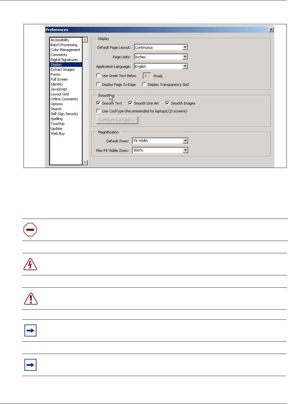
34 Preface
P0993133 03
Figure 1 Acrobat Reader display setup selections
Symbols used in this guide
This guide uses the following symbols to draw your attention to important information:
Caution: Caution Symbol
Alerts you to conditions where you can damage the equipment.
Danger: Electrical Shock Hazard Symbol
Alerts you to conditions where you can get an electrical shock.
Warning: Warning Symbol
Alerts you to conditions where you can cause the system to work improperly or to fail.
Note: Note Symbol
Alerts you to important information.
Tip: Tip Symbol
Alerts you to additional information that can help you perform a task.

Preface 35
Business Communication Manager 3.0 Installation and Maintenance Guide
Text conventions
This guide uses the following text conventions:
Acronyms
This guide uses the following acronyms (alphabetical order):
Warning: Grounding Symbol.
Alerts you to ground yourself with an antistatic grounding strap before performing the
maintenance procedure.
Warning: Disconnect Symbol
Alerts you to remove the Business Communications Manager and Business
Communications Manager expansion cabinet power cords from the AC outlet before
performing any maintenance procedure.
bold Courier text Indicates command names and options and text that you need to enter in
a command-line interface.
Example: Use the dinfo command.
Example: Enter show ip {alerts|routes}.
italic text Indicates file and directory names, new terms, book titles, Web
addresses, and variables in command syntax descriptions.
bold text Indicates command names, screen titles, options and text for a graphical
user interface (GUI).
angle brackets (< >) Indicates a keyboard key press or simultaneous key presses, i.e.
<ENTER> or <CTRL j>
ANSI American National Standards Institute
ASM Analog station media bay module
AWG American wire gauge
BIOS Basic input output system
BPS Bits per second
BRI Basic rate interface media bay module
CAP Central answering position
CIR Committed information rate
CLID Calling line identification
CSMA/CD Carrier sense multiple access/collision detect
CSU Channel service unit
CTM Calling line trunk module
DECT Digital enhanced cordless telecommunications

36 Preface
P0993133 03
DIMM Dual in-line memory module
DLCI Data link connection indentifier
DN Directory number
DNS Domain name server
DPNSS Digital private network signalling system
DRT Delayed ring transfer to prime
DSM Digital station media bay module
DTM Digital Trunk media bay module
DTMF Dual tone multifrequency.
FEM Fiber expansion media bay module
HTTP Hypertext transfer protocol
Hz Hertz
I/C Intercom
IP Internet protocol
ISDN Integrated services digital network
Kbyte Kilobyte
LAN Local area network
MCDN Meridian customer-defined network protocol
MHz Megahertz
MSC Media services card
NIC Network interface card
OPX Off premises extension
PBX Private branch exchange
PCI Peripheral component interconnect
PEC III Processor expansion card, version III
PRI Primary rate interface
PSTN Public switched telephone network
QoS Quality of service
QSIG Q reference point signalling
RAM Random access memory
ROM Read only memory
SAPS Station auxiliary power supply
TAPI Telephony application program interface
TCP/IP Transmission control protocol/internet protocol
UTAM UTAM Inc.
VoIP Voice over IP
WAN Wide area network

Preface 37
Business Communication Manager 3.0 Installation and Maintenance Guide
Related publications
The following documents provide further information about the Business Communications
Manager, related media bay modules, extension equipment, and system applications and software:
•Business Communications Manager 3.0 Programming and Operations Guide (P0993211)
describes core system operational configuration and how to program the Business
Communications Manager equipment.
•Telephone Features Programming Guide (P0993136) provides feature descriptions and
programming for the numerous telephone features available to users through the buttons on
digital telephone sets.
•Business Communications Manager 3.0 BIX Box Wiring Guide (P0993134) provides
illustrations for correctly wiring internal cable connections to telephones.
• All optional Business Communications Manager applications have installation and user guides
specific to that application. For an overview of these application user guides , refer to
“Telephony Features and Options” on page 353.
Guide type Title CPC code
CallPilot applications CallPilot Manager Set Up and Operation Guide P0919415
CallPilot Reference Guide P0919417
CallPilot Fax Set up & Operation Guide P0919426
CallPilot Fax User Guide P0919427
CallPilot Message Networking Setup and Operation Guide P0919429
CallPilot Message Networking User Guide P0919430
CallPilot Programming Record P0941757
CallPilot Unified Messaging Installation and Maintenance Guide P0945074
Call center applications Call Center Set Up and Operation Guide P0919436
Call Center Agent User Guide P0919437
Call Center Supervisor User Guide P0919438
Call Center Reporting Set Up and Operation Guide P0919439
Multimedia Call Center Setup and Operation Guide P0935737
Multimedia Call Center Web Developers Guide P0935740
Applications Personal Call Manager User Guide P0936569
Attendant Console Setup and Operation Guide P0936570
Attendant Console User Guide P0936571
Call Detail Recording System Administration Guide P0993139
Installation & Maintenance LAN CTE Configuration Guide P0993138
IP Telephony Configuration Guide P0993474

38 Preface
P0993133 03
How to Get Help
Your local distributor provides technical support for your Business Communications Manager
system or has access to that information through a Technical Service Center (TSC).
If you require non-technical support, contact 1-800-4NORTEL (1-800-466-7835), choose option
3, Sales or Pre-Sales Support)
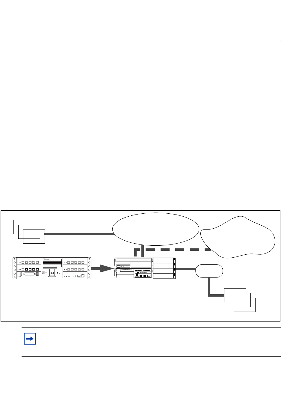
39
Installation and Maintenance Guide
Chapter 1
Introduction to the Business Communications
Manager Platform Hardware
The Nortel Networks Business Communications Manager (BCM) system provides private
network and telephony management capability to small and medium-sized businesses. The
Business Communications Manager integrates voice and data capabilities, VoIP gateway functions
and quality of service (QoS) data-routing features into a single telephony system. Business
Communications Manager is a compact system that allows you to create and provide telephony
applications for use in a business environment.
The Business Communications Manager system includes software and hardware components that
provide data networking, telephony service, voice messaging and service applications.
The Business Communications Manager requires version 3.0 software and is available in the
following three product configurations:
• BCM200
• BCM400 Standard (STD)
• BCM400 Redundant feature option (RFO)
Figure 2 provides an overview of the core Business Communications Manager system.
Figure 2 Business Communications Manager core system components overview
Note: Some of the components described in this document are not available in all areas.
Ask your Business Communications Manager sales agent for information about
availability.
“Installation Process
Overview” on page 93
Business Communications Manager
PSTN
Business Communications
Manager features
Appendix D, “System Options
Internal sets
“Telephones and adapters”
on page 85
External sets
WAN network
“Data networking
components” on page 62

40 Chapter 1 Introduction to the Business Communications Manager Platform Hardware
P0993133 03
Business Communications Manager Field Replaceable Units
Table 2 provides a list of field replaceable units (FRUs) for the BCM200 and BCM400 base
hardware platforms. Use Table 2 to Table 7 as a reference when you need to order, replace or
install component hardware. The tables indicate the component’s product engineering code (PEC),
and references to the description and installation procedures. Note that the codes may change over
time; consult the catalogue for the latest information.
Table 2 Card field replaceable units
Component description BCM200 PEC BCM400 PEC FRU Description Installation
procedure
BCM embedded modem NTAB9854 NTAB9854 Modem card on
page 63 Install the modem
card on page 229
Media services card NT5B15AAAK NT5B15AAAH Media services
card (MSC) on
page 57
Install the media
services card
(MSC) on page
226
Media services PEC III NTBB80AAAB NTBB80AAAB page 60 Install a
processor
expansion card
(PEC) on page
233
WAN interface card with CSU/
V.35 (North America only) NTAB3212 NTAB3212 WAN interface
card on page 62 Install the WAN
card on page 221
WAN interface card with CSU/
V.35/ X.21 (International only) NTAB3213 NTAB3213 WAN interface
card on page 62 Install the WAN
card on page 221
256MB memory module NTAB3421 NTAB3421 Main card on
page 60 Install the dual
in-line memory
module (DIMM)
card on page 237
Table 3 Chassis field replaceable units
Component description BCM200 PEC BCM400 PEC FRU Description Installation
procedure
Base function tray NTAB9858 NTAB9857 Base Function
Tray Component
Hardware on
page 54
Install the base
function tray on
page 151

Chapter 1 Introduction to the Business Communications Manager Platform Hardware 41
Installation and Maintenance Guide
Wall mount kit NTAB3422 NTAB3422 Install the
Platform Base
Chassis on the
Wall on page 102
BCM Field redundancy upgrade
kit Not applicable NTAB3420 BCM400 platform
redundant
feature option
(RFO)
configuration on
page 49
•Upgrade to a
redundant power
supply on page
203
•Hard Disk
Replacement
Procedures on
page 165
•Install or
Replace a
Cooling Fan on
page 179
Table 4 Hard drive field replaceable units
Component description BCM200 PEC BCM400 PEC FRU description Installation
procedure
BCM 3.0 hard drive,
Programmed (20GB) NTAB3392 NTAB3392 Hard Disk on
page 67 Install a New
Hard Disk on
page 171
BCM RAID upgrade kit NTAB9861 NTAB3418 RAID upgrade kit
on page 67 Hard Disk
Replacement
Procedures on
page 165
BCM replacement blank hard
drive NTAB3316 NTAB3316 Hard Disk on
page 67 Hard Disk
Replacement
Procedures on
page 165
Table 3 Chassis field replaceable units
Component description BCM200 PEC BCM400 PEC FRU Description Installation
procedure

42 Chapter 1 Introduction to the Business Communications Manager Platform Hardware
P0993133 03
Table 5 Power supply field replaceable units
Component description BCM200 PEC BCM400 PEC FRU Description Installation
procedure
BCM Universal power supply NTAB3423 NTAB3423 Platform Power
Supply on page
65
Replace a
Standard Power
Supply on page
192
BCM400 redundant power
supply module (single) Not applicable NTAB3419 BCM400
redundant power
supply on page
66
Upgrade to a
redundant power
supply on page
203
Table 6 Cooling fan field replaceable units
Component description BCM200 PEC BCM400 PEC FRU Description Installation
procedure
BCM2.5/BCM400 Cooling fan
(4-wire base unit) Not applicable NTAB3315 Cooling Fan on
page 68 Install a BCM400
cooling fan on
page 182
BCM Expansion Unit Cooling
Fan FRU Not applicable NTAB9650 Cooling Fan on
page 68 Install an
expansion unit
fan on page 190
BCM200 Chassis cooling fan NTAB3424 Not applicable Cooling Fan on
page 68 Install the
BCM200 cooling
fan on page 187
Table 7 Media bay module
Component description BCM200 PEC BCM400 PEC FRU Description Installation
procedure
BCM MBM Bay Filler Blanking
Plate FRU NTAB3279 NTAB3279 BCM MBM Metal
filler Install a Media
Bay Module on
page 109
DTM MBM NT7B04AAAC NT7B04AAAC Digital trunk media
bay module on
page 75
Install a Media
Bay Module on
page 109
CTM4 - CLID Trunk MBM NT5B18AAAD NT5B18AAAD Caller ID trunk
media bay module
on page 76
Install a Media
Bay Module on
page 109
CTM8-CLID MBM NT5B18ABAA NT5B18ABAA Caller ID trunk
media bay module
on page 76
Install a Media
Bay Module on
page 109
BRI S/T MBM NT7B76AAAH NT7B76AAAH Basic rate interface
media bay module
on page 77
Install a Media
Bay Module on
page 109

Chapter 1 Introduction to the Business Communications Manager Platform Hardware 43
Installation and Maintenance Guide
DSM-16+ MBM NT7B08AAAD NT7B08AAAD Digital station
media bay module
(DSM) on page 78
Install a Media
Bay Module on
page 109
DSM-32+ MBM NT7B09AAAC NT7B09AAAC Digital station
media bay module
(DSM) on page 78
Install a Media
Bay Module on
page 109
CMB4X16 MBM NT5B42AAAA NT5B42AAAA 4X16 Media Bay
Module on page
79
Install a Media
Bay Module on
page 109
ASM8 MBM NT7B16AAAE NT7B16AAAE Analog station
media bay module
on page 80
Install a Media
Bay Module on
page 109
FEM6 MBM NT7B07AAAC NT7B07AAAC Fiber expansion
media bay module
(FEM) on page 82
Install a Media
Bay Module on
page 109
DDIM MBM NT5B52AAA NT5B52AAA Digital Drop &
Insert MUX (DDIM)
on page 83
Install a Media
Bay Module on
page 109
Table 7 Media bay module
Component description BCM200 PEC BCM400 PEC FRU Description Installation
procedure
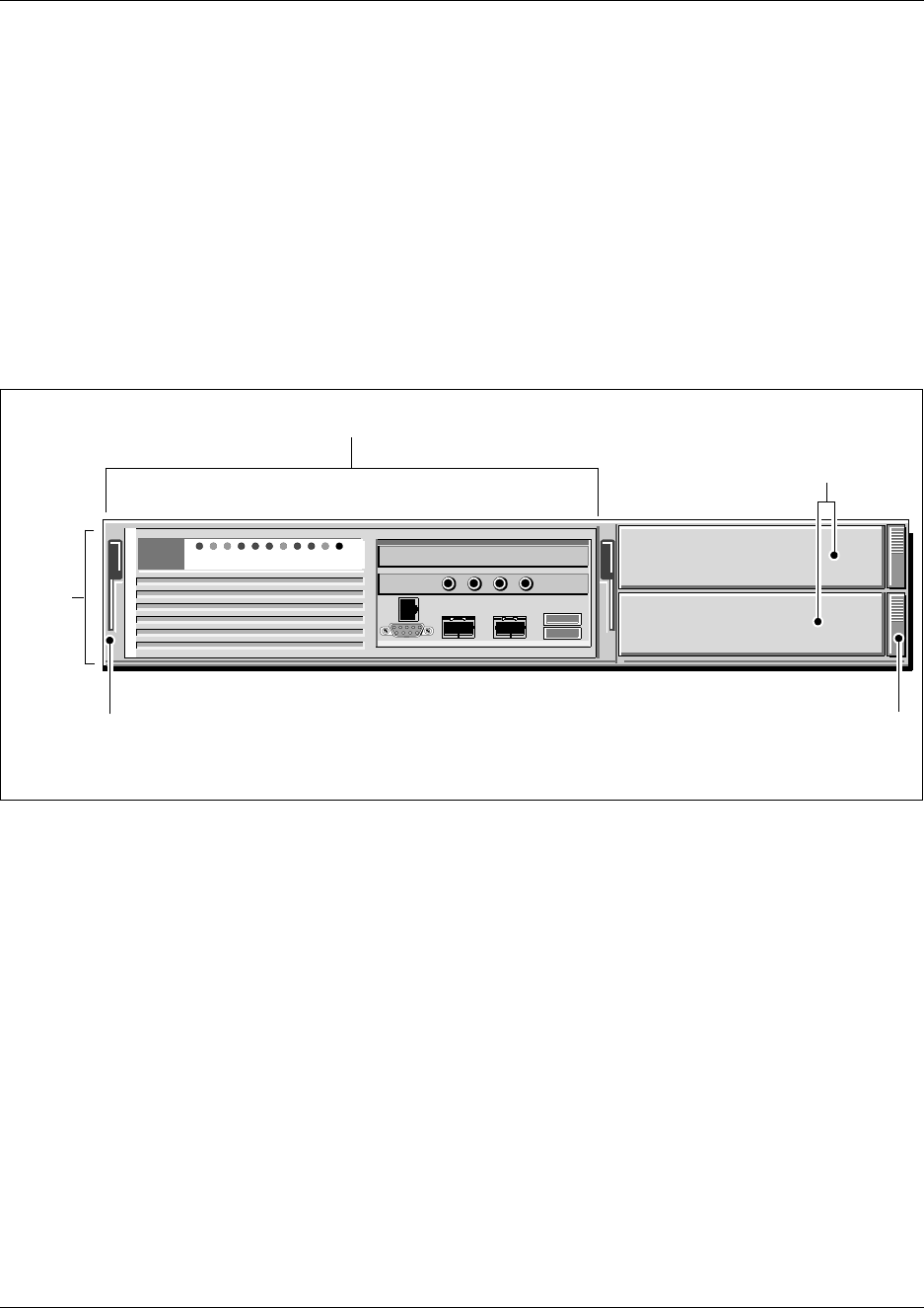
44 Chapter 1 Introduction to the Business Communications Manager Platform Hardware
P0993133 03
BCM200 Platform Base Hardware
The BCM200 platform base hardware has the following primary components:
• 1 x Platform base chassis (see “BCM200 platform base chassis” on page 44)
• 2 x Media bay module bays (MBM) (see “Media bay modules (MBMs)” on page 71)
• 1 x Sliding base function tray (BFT) (see “Base Function Tray Component Hardware” on page
54)
Figure 3 illustrates the BCM200 configuration primary components. The figure shows the base
function tray installed in the BCM200 platform base chassis.
Figure 3 BCM200 platform base chassis and primary components
BCM200 platform base chassis
The BCM200 platform base chassis design provides multiple points of access to the base platform
hardware components. The front of the chassis has three assemblies that house one base function
tray and two media bay modules (MBMs). The rear of the chassis provides mount points for the
fan and power supply. The rear of the chassis also has a removeable panel to provide access to the
hard disk. The top cover has a removable section to allow access to the cables, connectors, power
supply, hard disk and cooling fan.
Rack mount brackets allow you to install the chassis in a server rack. An optional wall mount
bracket is avialable separately. Rubber feet attach under the platform base chassis if you want to
place the Business Communications Manager unit on a flat surface. For further information on
chassis bracket installation, refer to Chapter 3, “Install the Business Communications Manager &
Expansion Unit Platform Base Chassis’.
Base function
tray latch
Platform
base
chassis
MBM
ejector
2 x Media bay module (MBM) bay
s
Base function tray
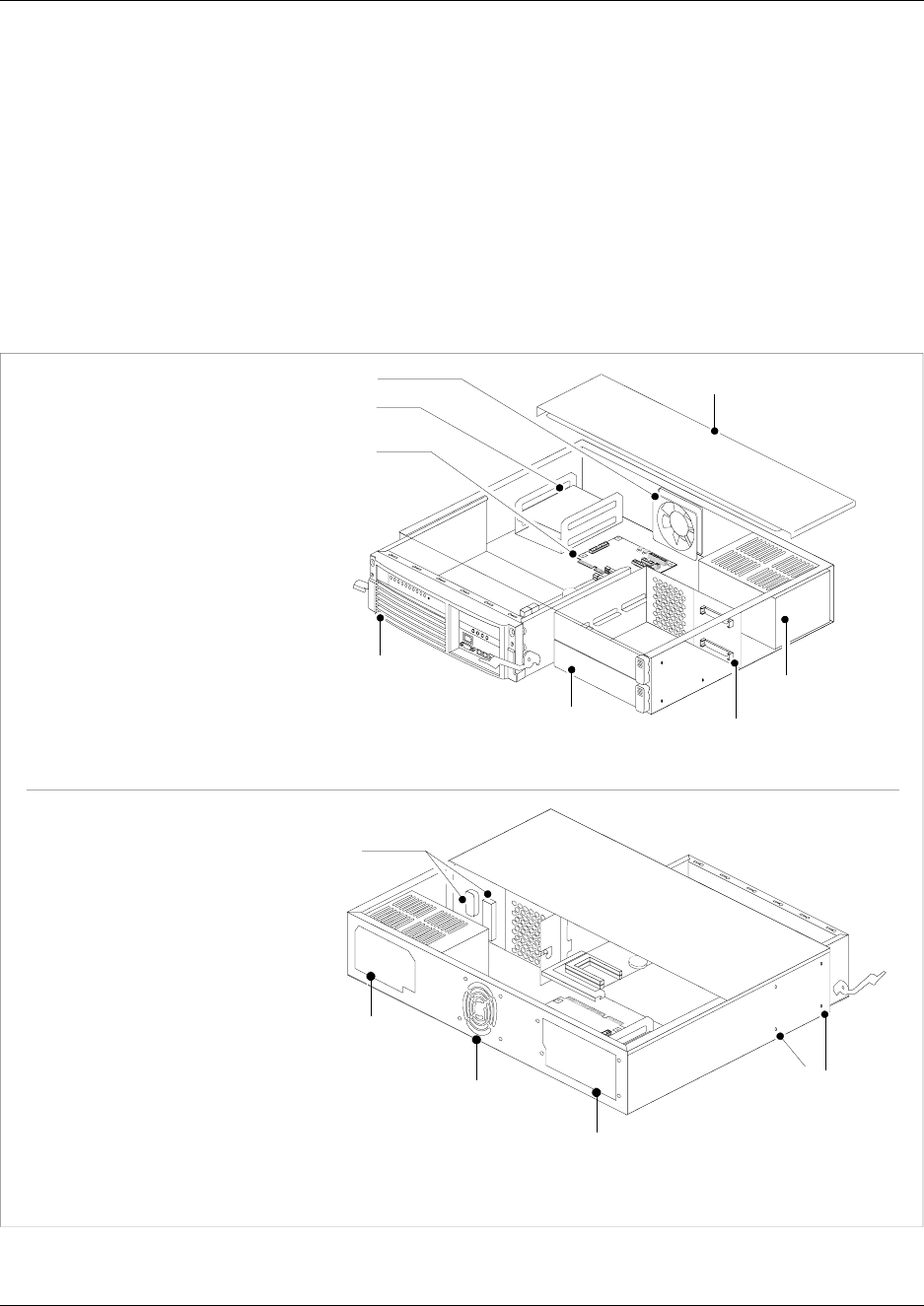
Chapter 1 Introduction to the Business Communications Manager Platform Hardware 45
Installation and Maintenance Guide
The chassis interior contains the following hardware components:
• 1 x Programed hard drive (or field redundancy upgrade provides an additional hard disk and
RAID controller card) - see “Hard Disk” on page 67.
• 1 x Auto-sensing power supply (standard) - see “Platform Power Supply” on page 65.
• 1 x System cooling fan - see “Cooling Fan” on page 68.
Figure 4 shows the location of the hardware components in the BCM200 platform base chassis.
Nortel Networks recommends that you know the location of the different components before
attempting to install or maintain the system.
Figure 4 BCM200 platform base chassis
Rear view
Base function
tray (x1)
Media bay
module bays (x2)
Power supply
bay
Hard disk bay
(removeable
panel)
Removable cover
Power supply
Hard disk
Fan
Media bay module
backplane
I/O card
Front view
Fan
exhaust Rack-mount
adapter anchor
points
Media bay module
backplane connectors
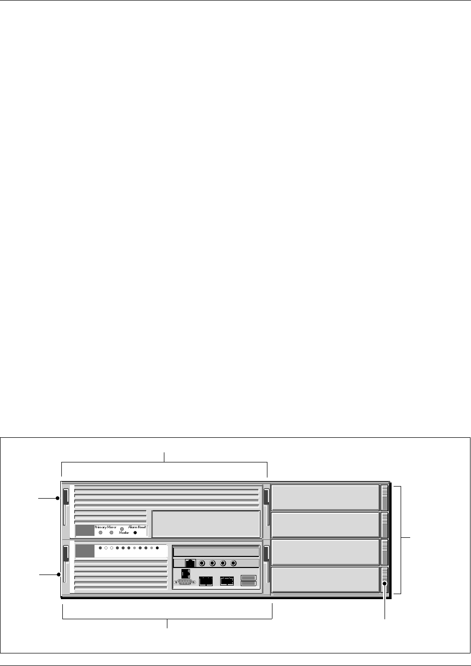
46 Chapter 1 Introduction to the Business Communications Manager Platform Hardware
P0993133 03
BCM400 Platform Base Hardware
The BCM400 platform consists of a platform base chassis equipped with advanced and base
function trays, and four media bay module bays. The advanced function tray contains a hard disk
and a bay for future use. The base function tray provides call processing functions and interface
connections. The media bay modules provide telephony features.
Rack mount brackets allow you to install the chassis in a server rack. Rubber feet attach under the
platform base chassis if you want to mount the Business Communications Manager unit on a flat
surface. An optional wall mount bracket is available.
The BCM400 platform is available either in a Standard (STD) or Redundant Feature Option (RFO)
configuration. The BCM400 STD and RFO platform base hardware share the following common
components:
• 1 x Platform base chassis
• 1 x Sliding advanced function tray (AFT)
• 4 x Sliding media bay module bays (MBM)
• 1 x Sliding base function tray (BFT)
The BCM400 RFO additional components are as follows:
• RAID controller card
• Additional hard disk for RAID controller card
• Redundant chassis cooling fan and fan panel
• Redundant power supply cage and power supply modules
Figure 5 illustrates the BCM400 RFO configuration. The figure shows the base and advanced
function trays installed in the BCM400 platform base chassis.
Figure 5 BCM400 platform base chassis and primary components
4 x Media
bay module
(MBM) bay
s
Base
function
tray
latch
Advanced
function
tray latch
Base function tray
Advanced function tray
MBM ejector

Chapter 1 Introduction to the Business Communications Manager Platform Hardware 47
Installation and Maintenance Guide
BCM400 platform base chassis
The BCM400 platform is available in either a standard (STD) or RFO configuration. Nortel
Networks recommends that you know the location of the different components before attempting
to install or maintain the system.
The BCM400 platform base chassis design provides multiple points of access to the base platform
hardware components. The front of the chassis has two, sliding tray assemblies that house the base
function tray and advanced function tray. Four bays accomodate the media bay modules (MBMs).
For more information on the chassis interior hardware components, see Media bay modules
(MBMs) on page 71.
The rear of the chassis provides mount points for the fan and power supply. The top cover has
fixed and removable sections. Remove the rear portion of the cover to access the cabling, power
supply cage and hard disk components. Chassis adapters allow you to install the chassis in a server
rack. An optional wall mount bracket is available separately.
BCM400 standard (STD) configuration hardware components
The BCM400 standard configuration is equipped as follows:
• 1 x Main card
• 1 x Media services card (MSC) with 2 processor expansion cards (2 additional cards can be
added)
• 1 x Programed hard drive
• 1 x auto-sensing power supply
• 1 x System cooling fan
Figure 6 shows the location of the hardware components (standard configuration) in the BCM400
platform base chassis.
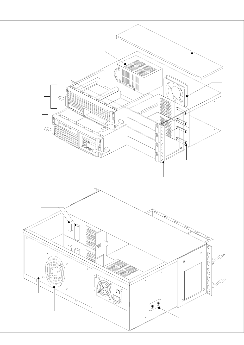
48 Chapter 1 Introduction to the Business Communications Manager Platform Hardware
P0993133 03
Figure 6 BCM400 platform base chassis (standard configuration)
Front view
Advanced
function tray
Base
function tray
Chassis rack-mount
bracket
Power supply
Fan
Media bay module
backplane
Rear view
Fan access
panel
Fan exhaust Power supply
support bracket
mount
Removable cover
Media bay
module
backplane
connectors
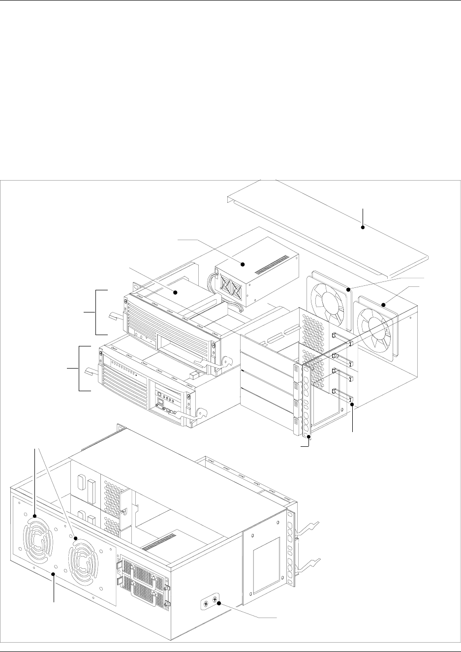
Chapter 1 Introduction to the Business Communications Manager Platform Hardware 49
Installation and Maintenance Guide
BCM400 platform redundant feature option (RFO) configuration
Figure 7 shows the location of the hardware components in the RFO configuration platform base
chassis.
• 1 x Media services card (MSC) with 2 processor expansion cards (2 additional cards can be
added.
• 2 x hard disks and RAID controller card
• 2 x System cooling fans
• 2 x Redundant, hot-swappable power supply modules
Figure 7 BCM400 platform base chassis (RFO configuration)
Front view
Advanced
function tray
Base function
tray
Chassis rack-mount bracket
Power supply
Fans
Media bay module
backplane
Removable cover
Rear view
Fan access
panel
Power supply
support bracket
mount
Fan exhaust
2 x hard disks &
RAID
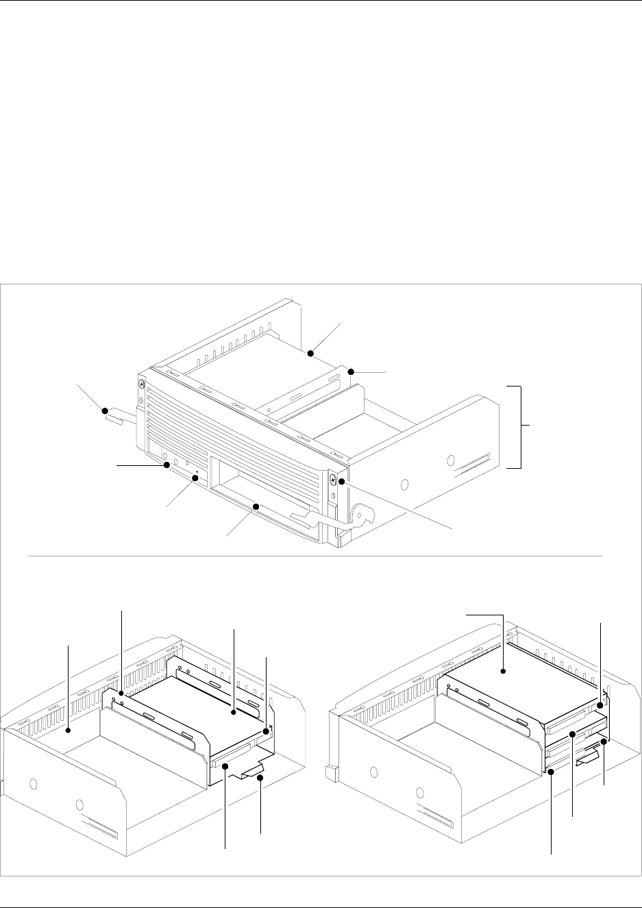
50 Chapter 1 Introduction to the Business Communications Manager Platform Hardware
P0993133 03
BCM400 advanced function tray (AFT)
The advanced function tray (AFT) houses the hard disk and an extra, unpopulated bay. The
standard configuration contains a single hard disk and has no RAID LED display. The AFT, in the
RFO configuration contains two hard disks, a RAID controller card and has an LED display to
monitor RAID status. The extra, unpopulated bay is reserved for future development. The
advanced function tray mounts in the upper BCM400 platform base chassis bay. The advanced
function tray slides out and away from the front of the chassis for hard disk maintenance, RAID
upgrade or exchange purposes.
Figure 8 illustrates the advanced function tray chassis and faceplate interfaces for the BCM400
standard (STD) and redundant feature option (RFO) platform configurations.
Figure 8 Advanced function tray
Reserved bay
IDE connector
Advanced function tray face with single hard disk
Advanced function
tray chassis
Status LEDs
(RAID only)
Reset button
Reserved bay
Advanced function
tray latch
Bezel screw
Hard disk cage
Primary disk
Power supply
connector
Primary disk Power supply
connector
Advanced function tray RFO configuration
Mirror
disk
IDE connector
Hard disk cage
Hard disk
cage lift tab
RAID
card
Hard disk
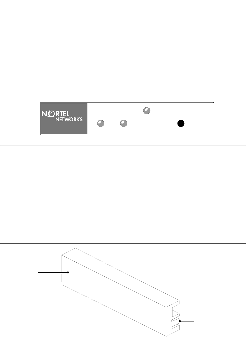
Chapter 1 Introduction to the Business Communications Manager Platform Hardware 51
Installation and Maintenance Guide
BCM400 advanced function tray RAID status LEDs
Three LEDs are located on the bezel face of the advanced function tray. The LEDs show the
current state of RAID hardware components.
The RAID status LEDs indicate monitoring of the following:
• Primary hard disk activity
• Mirror hard disk activity
• Card status activity
Figure 9 Advanced function tray RAID status LEDs
Platform Media Bay Module Bays and Backplane
The number and configuration of the media bay modules depend on the number of bays available
in the platform base chassis and DS30 system resources. The BCM200 platform base chassis
provides two media bay module bays. The BCM400 platform base chassis provides four media
bay module bays.
All media bay module bays must contain either a media bay module or a MBM filler blanking
plate. Populate the bays with media bay modules as required. Fill unpopulated media bay module
bay openings in the platform base chassis with the MBM filler blanking plate (see Figure 10).
Figure 10 Media bay module filler blanking plate
Primary Mirror
Status
Alarm Reset
Filler blanking
plate face
Locking clip
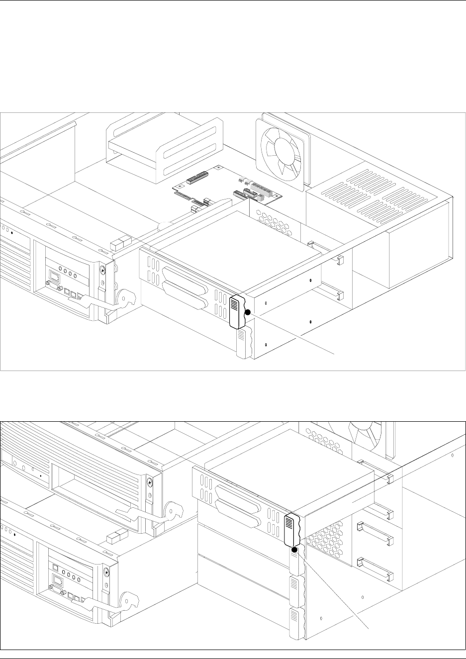
52 Chapter 1 Introduction to the Business Communications Manager Platform Hardware
P0993133 03
The media bay modules slide into the MBM bays and lock into place. Pull on the MBM ejector to
release the MBM or filler blanking plate. The module or filler blanking plate partially ejects from
the bay. Slide the the media bay module out of the bay to remove from the platform base chassis.
Figure 11 shows the BCM200 platform MBM bays and release mechanism.
Figure 11 BCM200 media bay module bays
Figure 12 shows the BCM400 platform MBM bays and release mechanism.
Figure 12 BCM400 Media bay module bays
Ejector
Ejector
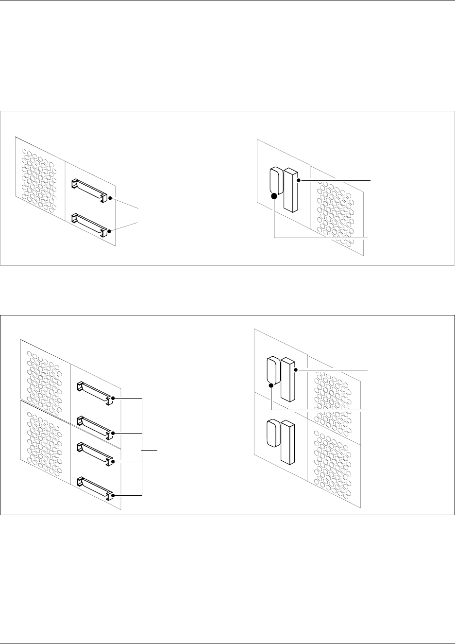
Chapter 1 Introduction to the Business Communications Manager Platform Hardware 53
Installation and Maintenance Guide
The media bay module (MBM) backplane provides the media bay module component interface to
the power supply and main card. The media bay module backplane mounts at the rear of the media
bay module bays and is a non-replaceable chassis component. Figure 13 illustrates the media bay
module backplane and connectors for the BCM200 platform. Figure 14 illustrates the media bay
module backplane and connectors for the BCM400 platform.
Figure 13 BCM200 media bay module backplane
Figure 14 illustrates the BCM400 media bay module backplane and connectors.
Figure 14 BCM400 media bay module backplane
MBM
backplane
connectors
Front view Rear view
MBM backplane
connector to
MSC
MBM backplane
connector to
power supply
Front view
MBM backplane
connector to
MSC
MBM backplane
connector to
power supply
MBM
backplane
connectors
Rear view
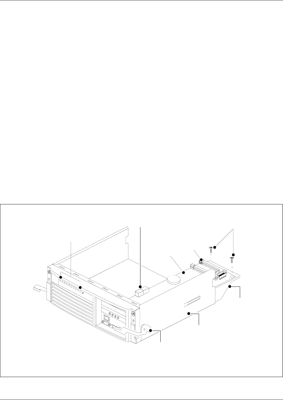
54 Chapter 1 Introduction to the Business Communications Manager Platform Hardware
P0993133 03
Base Function Tray Component Hardware
The base function tray hardware controls all data and telephony tasks, such as call processing,
voice messaging, and data routing. The base function tray contains the following hardware
components:
• 1 x Base function tray chassis
• System status display (LEDs)
• 1 x Media services card
• 1 x Main card
• 1 x Wide area network (WAN) card (available only as a field upgrade)
• Processor expansion cards (PEC III) - (1 for BCM200 or 2 for BCM400)
• 1 x V.90 modem (North America only)
Base function tray chassis
The base function tray installs in the platform base chassis and houses the main card with the
system interfaces.
Figure 15 illustrates the base function tray chassis layout (BCM200 configuration shown).
Figure 15 Base function tray hardware and chassis
Base
function tray
chassis
Base
function tray
latch
Base function
tray chassis
extension
MSC
System status
display LEDs
DS30
Connectors MSC chassis
mounting screws
PEC III
slots
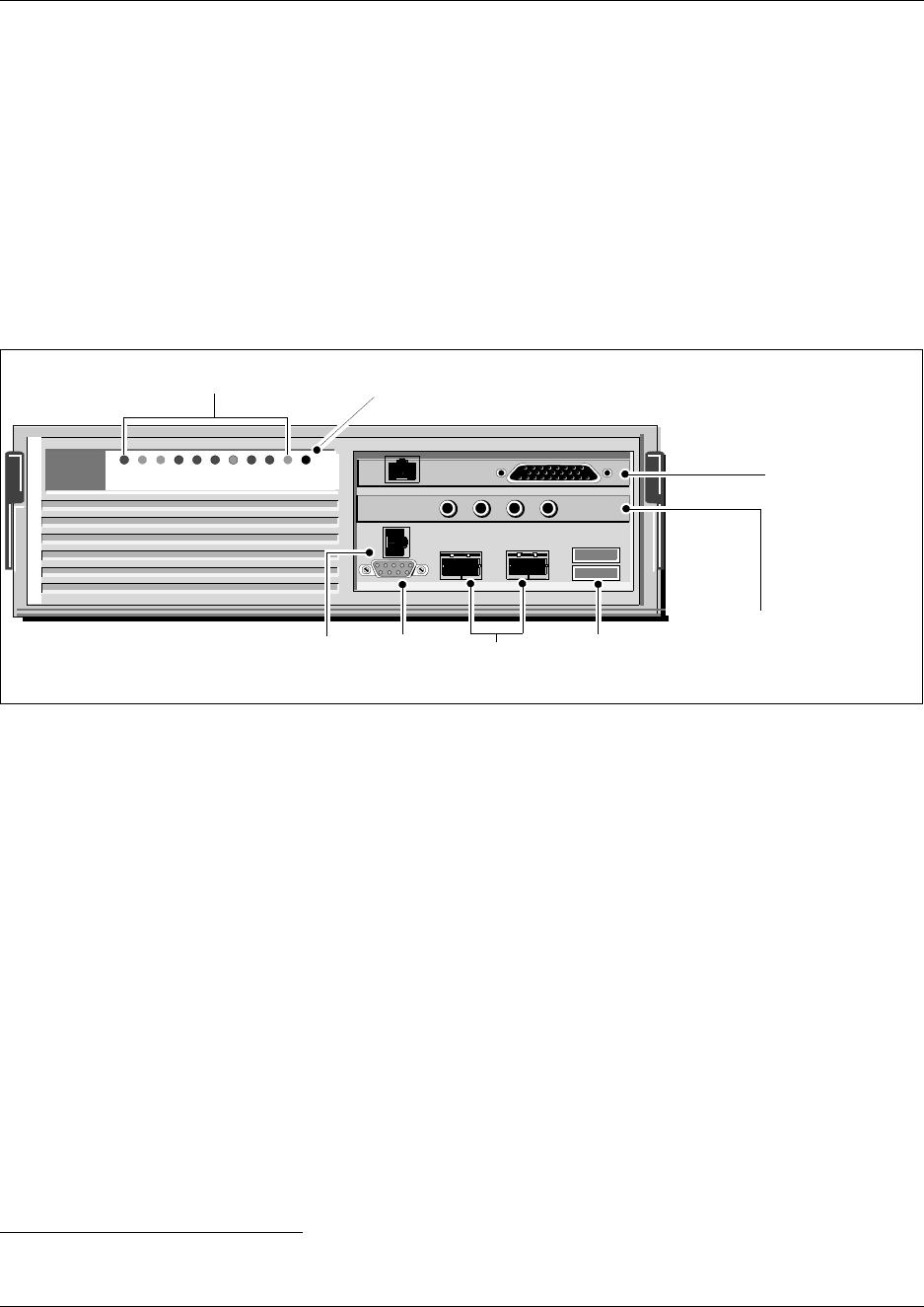
Chapter 1 Introduction to the Business Communications Manager Platform Hardware 55
Installation and Maintenance Guide
Base function tray interfaces
You can connect to the base function tray through the serial port or through a LAN port to perform
the system initialization. The data networking components connect the Business Communications
Manager system to your local area network (LAN) and/or the wide area network (WAN).
For initialization information, refer to “Use of a null modem serial cable” on page 137 and
“Connect the Ethernet crossover cable” on page 141.
Figure 16 illustrates the base function tray ports for the BCM200 platform.
Figure 16 Base function tray faceplate ports
Base function tray system status display LEDs
A line of 10 LEDs display on the face of the base function tray (see Figure 17). The LEDs show
the current state of various hardware components. The Unified Manager contains a monitoring
tool, that allows you to determine the current condition of the LEDs from your computer. Refer to
“Access the System Status Monitor to Monitor LEDs” on page 292.
The system status LEDs indicate monitoring of the following:
• Power status (LED 1): Indicates the status of all power components. Green indicates normal
status. Red indicates an excessive voltage deficiency or a component failure (such as a
redundant power supply fan or module). An LED that monitors a component will also show a
fault in combination with the Power LED.
• Hard disk activity (LED 2): Green indicates hard disk access.
• System status (LED 3): Solid green indicates the system is normal and operational. Green
blink indicates one or more telephony services are not operational.1
1 Six, non-blinking LEDs in the center indicates monitoring software is not active.
Modem port (North
America only)
Media services
card (MSC1b)
USB
ports
Ethernet
ports
COM
port
WAN card (field
upgrade)
System status display LEDs Reset button

56 Chapter 1 Introduction to the Business Communications Manager Platform Hardware
P0993133 03
• PCI device monitoring (LED 4-8): These LEDs monitor the peripheral components (2 x NICs,
1 x WAN, 1 x Modem, 1 x MSC). A steady green LED indicates the device is detected and
operationally normal. A flashing green LED indicates that software detects the hardware, but
there is no device driver. No color indicates the device is defective or missing.
— LED 4: Monitors the MSC
— LED 5: Monitors the WAN (if installed)
— LED 6: Monitors the modem (if installed)
— LED 7: Monitors the NIC 1
— LED 8: Monitors the NIC 2
• Chassis/CPU temperature (LED 9): Green indicates a normal, operational temperature range
for the chassis. Red indicates either a sensor is not operational or the chassis temperature is out
of range.
• Fan activity (LED 10): Green indicates that all fans are operational. Red indicates that one (or
more) fan is not operating correctly.
• Reset button: The reset button when depressed, restarts the system. The reset button is
recessed to prevent an accidental reboot.
Note: The system status LEDs correspond to the devices, not to the PCI slots.
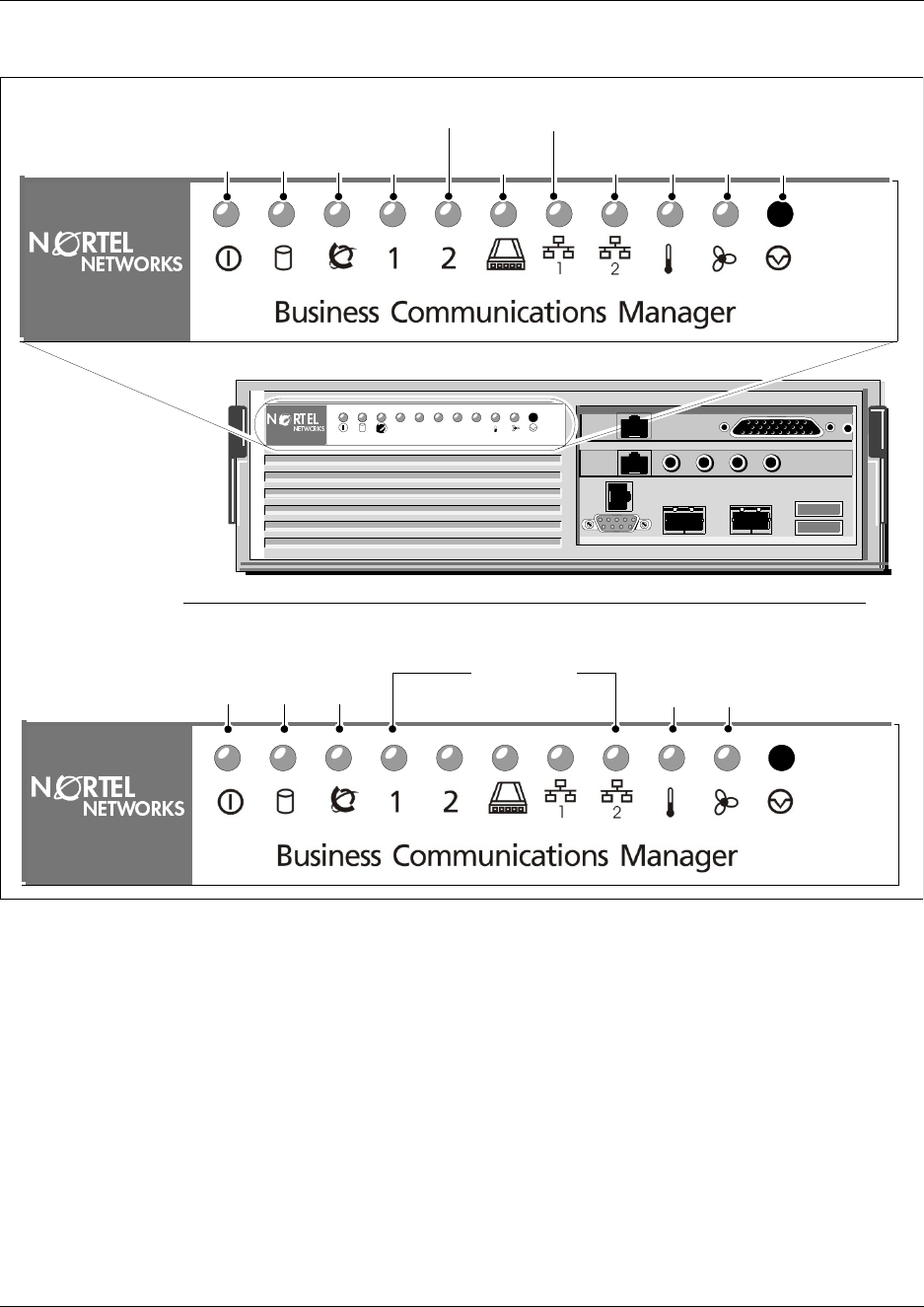
Chapter 1 Introduction to the Business Communications Manager Platform Hardware 57
Installation and Maintenance Guide
Figure 17 Business communication manager base function tray system status display LEDs
Media services card (MSC)
The Media Services Card (MSC), a PCI card, performs call processing and media processing of
the voice channels for the Business Communications Manager system, including the VoIP trunks.
This card also offers connections for auxiliary features, including external, customer-supplied
hardware for paging and music-on-hold.
Figure 18 shows the MSC components for the BCM200 platform. Figure 19 shows the MSC
components for the BCM400 platform.
12345
BCM400
Red or
Green Green
Flash Green
Blink Green Blink Red or
Green Red or
Green
BCM400
Power StatusDisk Temp ResetFanMSC
WAN
Modem
LAN 1
LAN 2
Red or Green
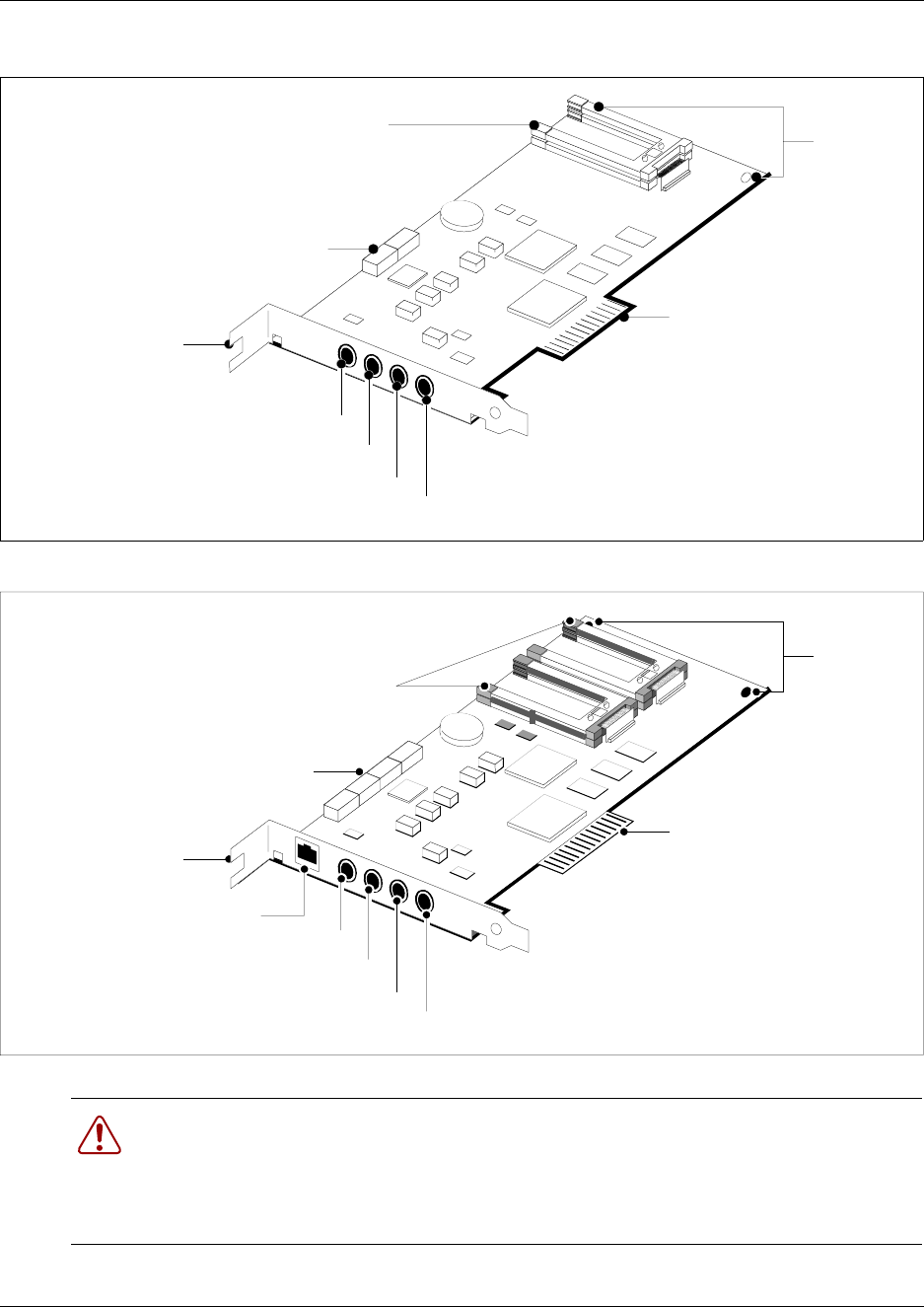
58 Chapter 1 Introduction to the Business Communications Manager Platform Hardware
P0993133 03
Figure 18 BCM200 Media services card
Figure 19 BCM400 Media services card
Warning: External equipment connected to the auxiliary ringer, page relay, page output
and music on hold interfaces must use safety extra low voltage (SELV).
All four interfaces are (SELV) and the external equipment connected to these interfaces
must be SELV. If these interfaces are not SELV, you must use external line isolation units
(LIU).
1 x PEC III
(2 slots)
Bracket
press plate
PCI connector
Auxiliary ringer
Page relay
Page output
Music on hold input
Chassis
mounting
screws
DS30
connectors
Bracket
press plate
PCI connector
Auxiliary ringer
Page relay
Page output
Music on hold input
2 x PEC III
(4 x slots)
Chassis
mounting
screws
DS256 (to expansion unit)
DS30
connectors

Chapter 1 Introduction to the Business Communications Manager Platform Hardware 59
Installation and Maintenance Guide
The MSC faceplate offers the following optional connections.
•DS256 connector (BCM400)— The Business Communications Manager expansion unit
connects to the base function tray through the DS256 jack on the MSC faceplate.
The DS256 cable to make this connection is provided with the purchase of an BCM1000e
expansion chassis.
•Auxiliary ringer jack — The base function tray uses the auxiliary ringer jack to control the
cadence of an auxiliary ringer (customer supplied). You must use this output in a low current,
low voltage application only. Do not use this output for switching the auxiliary ringer directly.
•Page relay jack — When you use the page signal output jack to connect an external paging
amplifier, you also use the page relay jack. The page relay jack connects a floating relay
contact pair. The base function tray uses this jack to control the external paging amplifier.
•Page output jack — The base function tray uses the page output to connect an internally
generated voice paging signal to an external paging amplifier (customer supplied).
•Music on hold jack — The base function tray uses the Music on hold input to connect an
external music source that supplies a signal to held lines (music on hold) or telephone speakers
(background music). The input source can be any available radio or music source approved for
connection to the network.
For directions on setting up these features, refer to “Media Service Card Connections” on page
287.
MSC IP call processing hardware
If your system requires a high volume of IP telephones and/or more IP trunks than the standard
eight trunks, you have the option to switch a DS30 bus setting on the MSC from providing service
for a media bay module, to providing digital processing service for additional IP telephones and/or
trunks. To ensure adequate data flow from the system, you can increase the number of PEC III
cards (BCM200 has a maximum of 2 cards, BCM400 has a maximum of 4).
• DS30 channels are internal communication paths. Each DS30 bus provides a possible 32
signaling channels and 32 media channels.
— two DS30 buses are exclusively dedicated to MSC data resources. Five paths within these
channels have hard-coded applications. The other paths can be assigned to various data
applications such as voice mail, dialup ISDN WAN, VoIP trunks, or IP telephony.
— five DS30 channels are exclusively reserved for the media bay modules
— The sixth DS30 bus can be switched to accommodate media bay modules or more
channels for IP telephones or VoIP trunks. You control the use of the channel by your
choice of using either a 2/6 or 3/5 DS30 bus split. This is set when you run the Quick Start
Wizard at the initial startup of the system.
For more details about deciding which DS30 bus configuration you want for your system,
refer to “Determining module channel requirements” on page 320 and to the chapter on
configuring MSC Resources in the Business Communications Manager 3.0 Programming
Operations Guide.
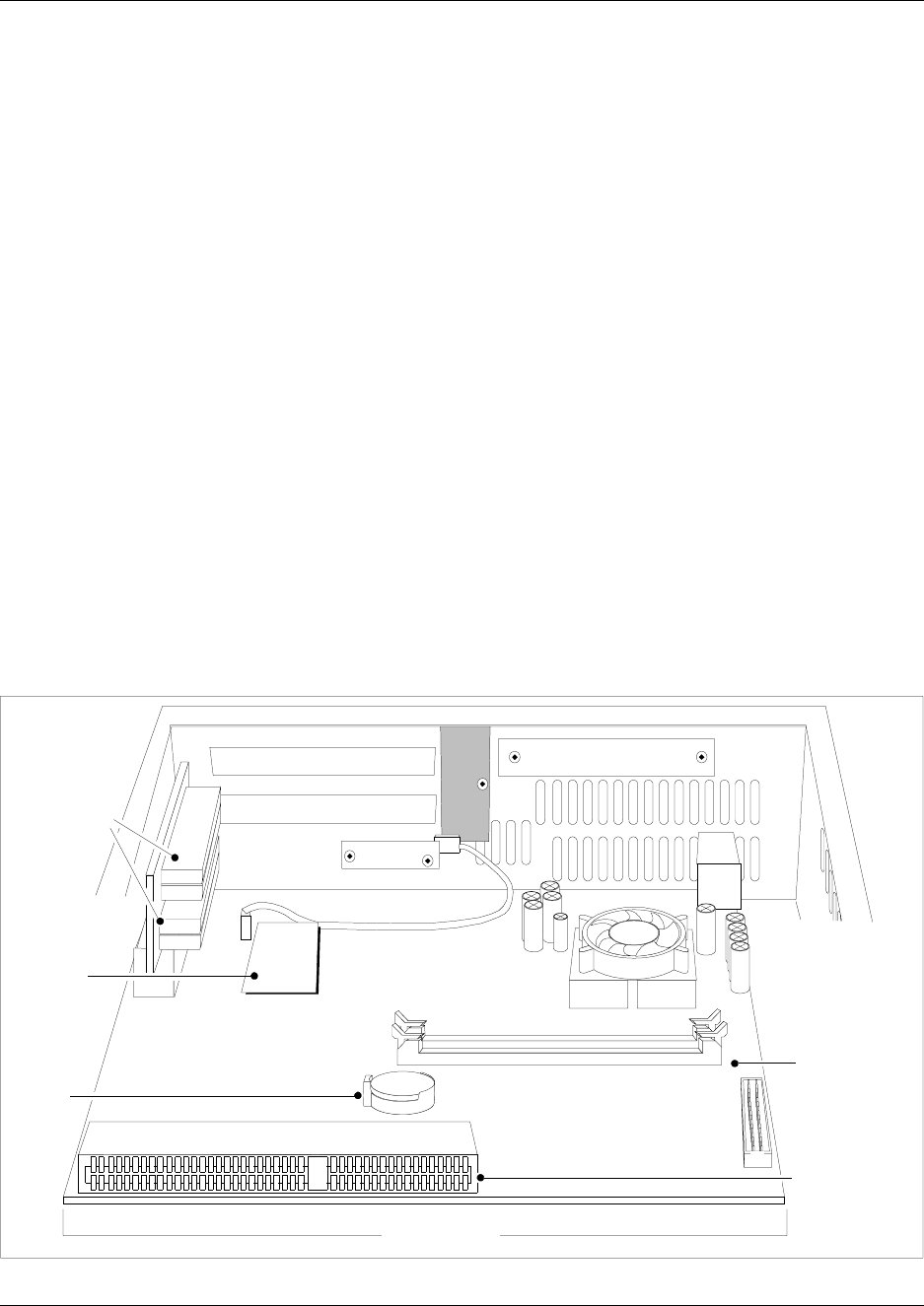
60 Chapter 1 Introduction to the Business Communications Manager Platform Hardware
P0993133 03
• PEC IIIs — The Business Communications Manager 3.0 uses PEC IIIs to deliver increased
capacity for digital signal processing for voice mail, call center, FAX, VoIP trunks, IP
telephony, and dialup ISDN WAN. The BCM200 platform uses one PEC III card (expandable
to 2). The BCM400 platform uses two PEC IIIs (expandable to 4) to accommodate increased
requirements for media processing. Refer to the chapter on configuring MSC Resources in the
Business Communications Manager 3.0 Programming Operations Guide.
Main card
The main card contains several field replaceable units (FRUs) such as the RAM, modem card and
CMOS battery. A riser card, set at right angles to the main card, provides connections for the MSC
and field installed wide area network card. In North America only, an embedded modem provides
connection for a backup analog trunk. Figure 20 shows the layout of the main card as installed in
the base function tray.
The main card contains the following hardware:
•1 x Processor
• 1 x 168-pin 256MB DIMM (maximum of 2 x 256MB DIMMS)
• 1 x modem card (North American system only)
• 1 x lithium coin battery cell (CMOS)
• 1 x 2-slot PCI riser card
Figure 20 Main card connectors
PCI Riser
card
connectors
Modem
card
Main card
DIMM
connectors
I/O card
connector
CMOS
battery
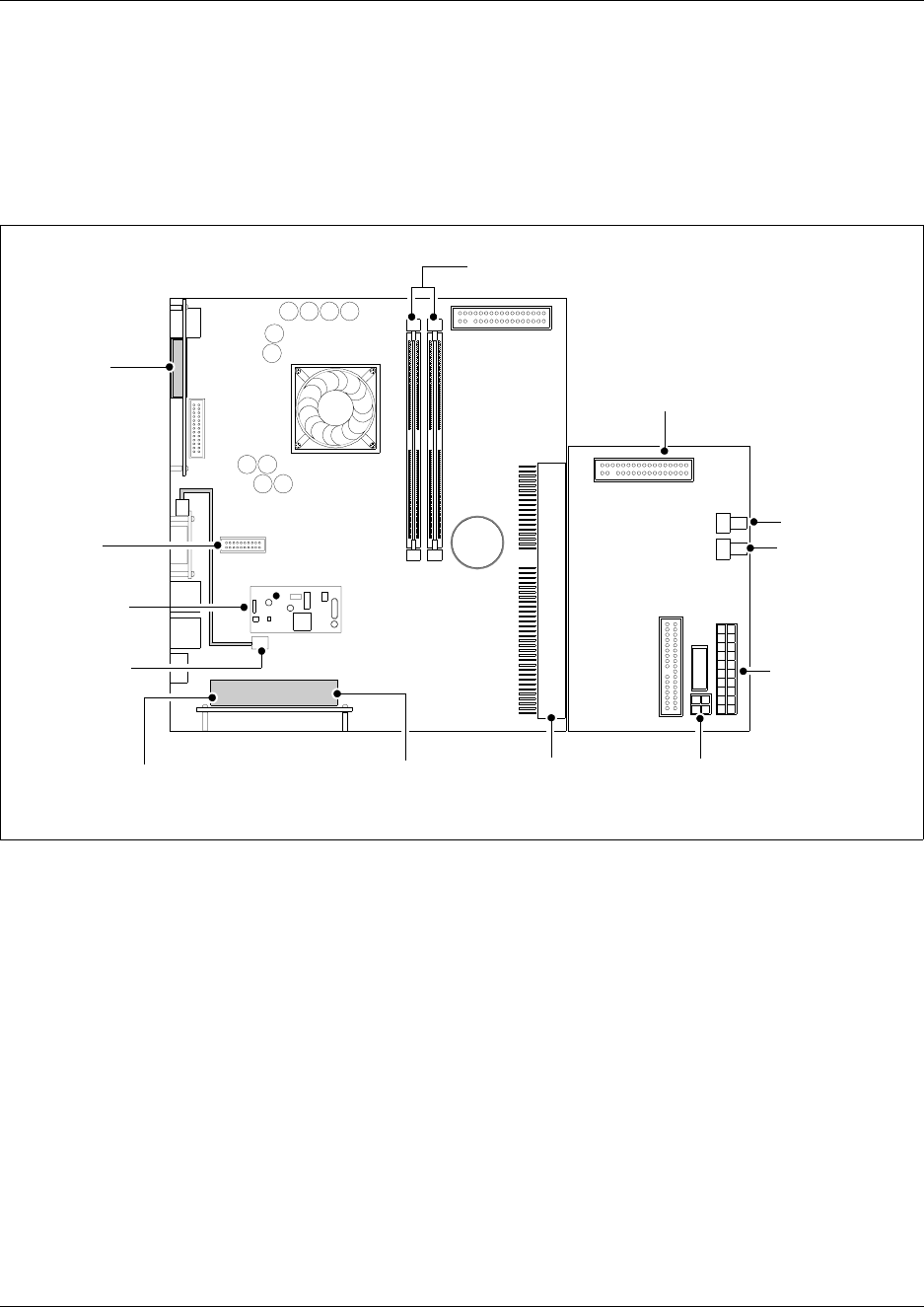
Chapter 1 Introduction to the Business Communications Manager Platform Hardware 61
Installation and Maintenance Guide
Main card connections
The main card provides peripheral and telephony processing control for the Business
Communications Manager system. The main card connects to the I/O card, system status display
(SSD) card, modem interface card. Figure 21 shows the main card and I/O card connectors.
Figure 21 Card connections
PCI riser card
The PCI riser card extends upward, and at a right angle, from the main card. The PCI riser card
provides a peripheral component interface (PCI) for the MSC and field installed WAN cards.
Figure 22 shows the PCI riser card installed in the Base function tray.
Figure 23 shows the PCI connectors without the MSC or WAN cards. Two screws at the top of the
PCI riser card attach the card to the side of the BFT chassis.
Connect to hard disk
I/O Card
Main Card
Connect to
single fan
Connect to
redundant
fan
Connect to
Power supply
(20 pin)
Connect to
Power supply
(PSU AUX)
Upper PCI riser
connection to
WAN card
Lower PCI riser
connection to
MSC
Modem card
connector
SSD board
connector
Main card
and I/O card
connector
SSD
connector
DIMM connectors
Modem card
Chassis
front Chassis
rear
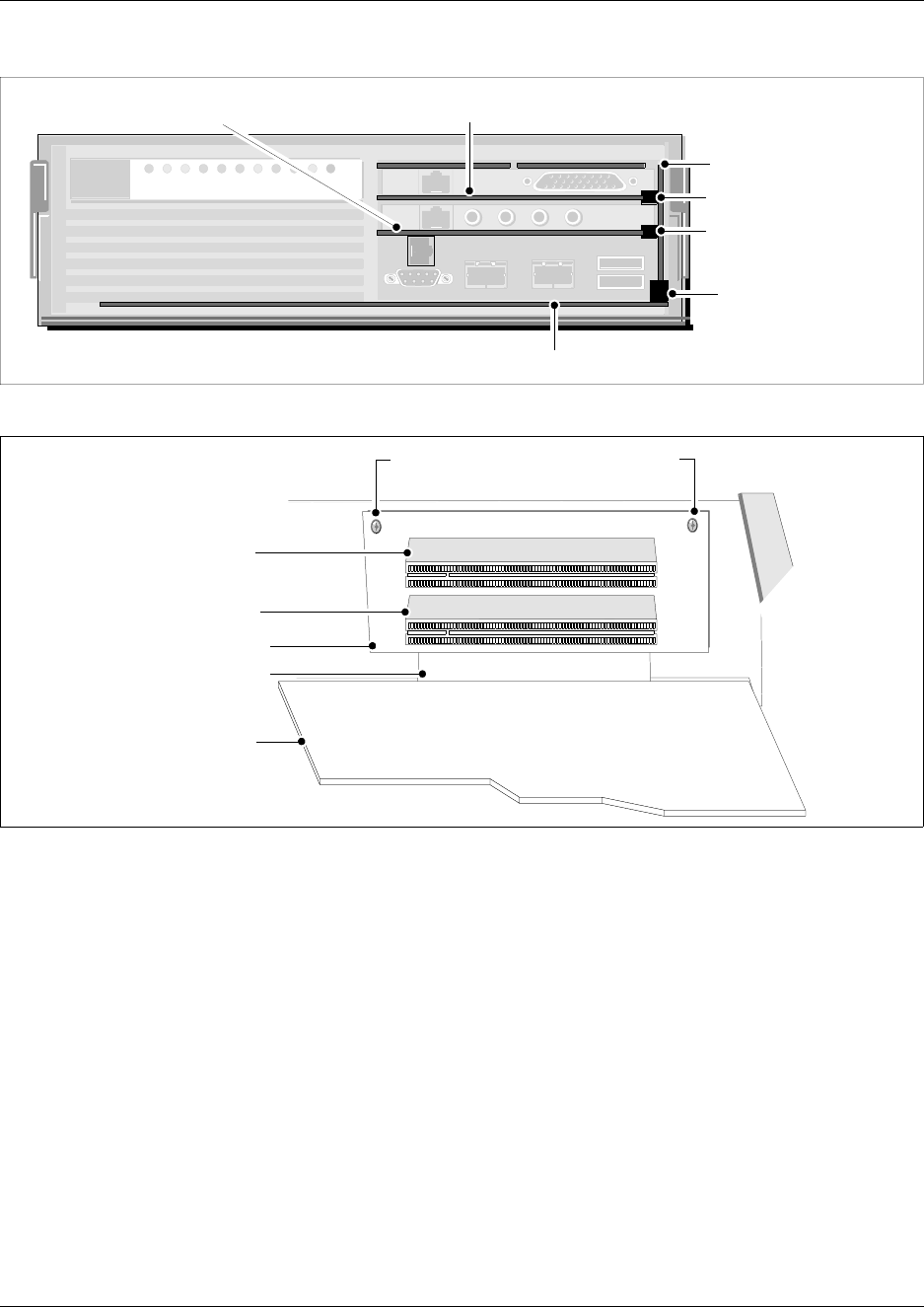
62 Chapter 1 Introduction to the Business Communications Manager Platform Hardware
P0993133 03
Figure 22 PCI Riser card
Figure 23 PCI Riser card connectors
Data networking components
The data networking components connect the Business Communications Manager system to the
wide area network (WAN).
WAN interface card
The network interface card uses a T1 interface and sync port that connects the Business
Communications Manager system to the wide area network (WAN). The WAN card is available as
a field installed unit.
The WAN card connects to a T1 PSTN line with an integrated T1 DSU/CSUs (North American).
The WAN card can also connect to a T1 PSTN line with an X.21 or V.35 interface (Europe, Middle
East, Africa (EMEA)).
PCI riser card
WAN PCI connector
MSC PCI connector
Main card/PCI riser
card connector
Main card
MSC WAN card (field installable)
PCI riser card
WAN PCI connector
MSC PCI connector
PCI Riser/Main card connector
Base
function
tray
chassis
front
PCI Riser card mounting screws
Main card
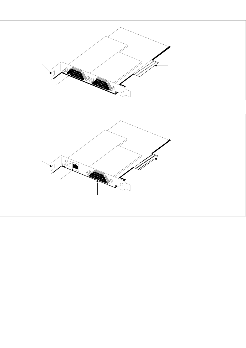
Chapter 1 Introduction to the Business Communications Manager Platform Hardware 63
Installation and Maintenance Guide
Figure 24 WAN interface card (international version)
Figure 25 WAN interface card (North American version)
Modem card
Modem card (Standard on North American systems, optional for APAC/EMEA) — a V.90 modem
that sends and receives data using the public telephone system. The modem kit consists of a
modem card, RJ11 interface and connector cable.
The modem connects the Business Communications Manager system to the public switched
telephone network. Figure 26 shows the modem components.
Use the modem connection to:
• manage the Business Communications Manager system from a different location
• provide dialup backup for a WAN card
PCI clamp
press plate PCI connector
DB25 female
connector
PCI clamp
press plate PCI connector
T1 CSU connector
DB25 female
connector
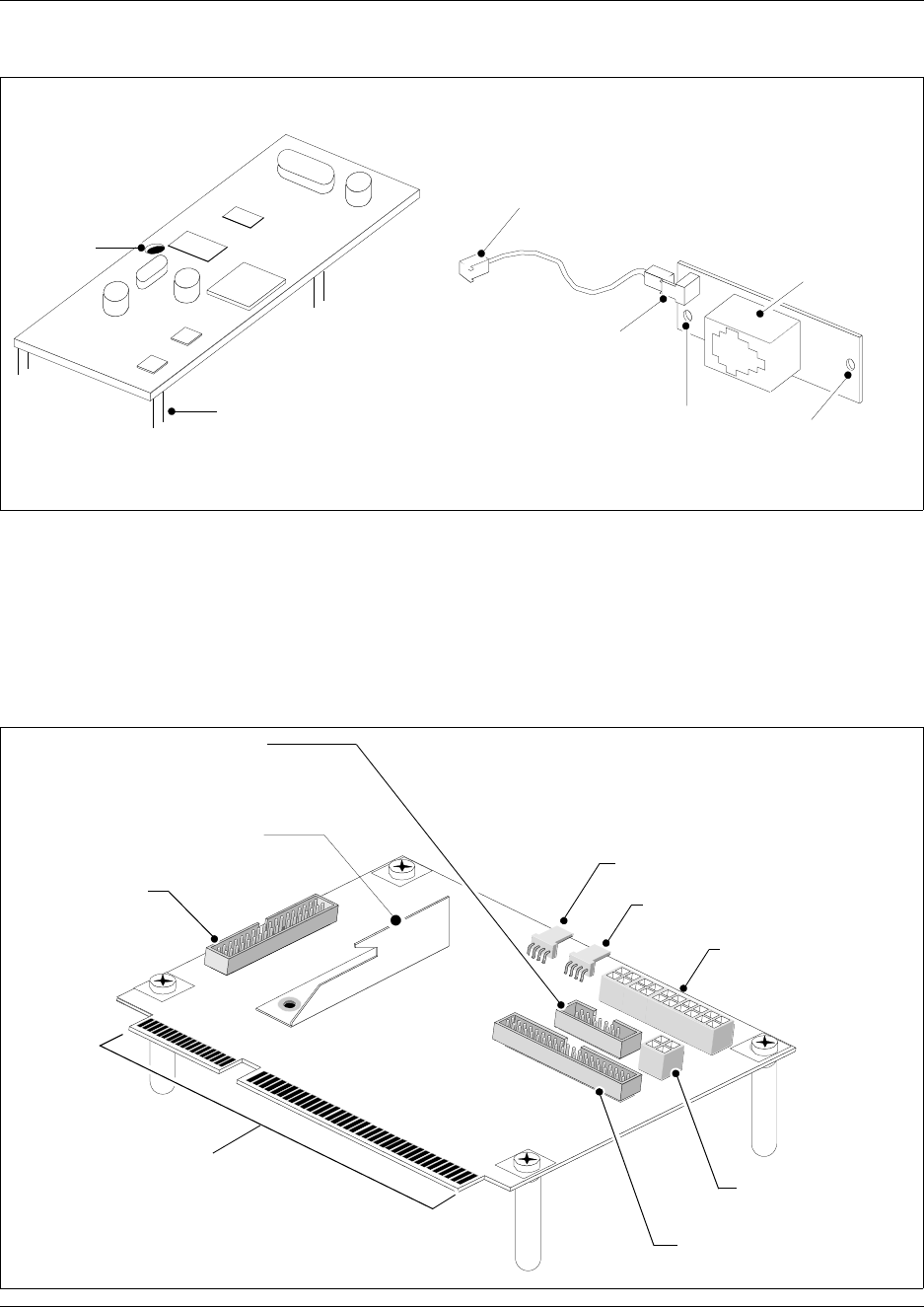
64 Chapter 1 Introduction to the Business Communications Manager Platform Hardware
P0993133 03
Figure 26 Modem card and interface
I/O Interface card
The I/O interface card is a provides signal junction between the Base function tray, hard disk,
power supply and cooling system. Figure 27 shows the I/O interface card and connections.
Figure 27 I/O interface card
Main card connector
RJ11 connector
(exposed on BFT
face)
2-pin connector
To Main card modem
socket connector
BFT mount points
Modem card
pin guide
Modem card RJ11 card interface
20-pin power
supply connector
PSU Status - RPS output
signalling connector
BFT connector
Chassis Fan 1 connector
Chassis Fan 2 connector
I/O Card
Primary IDE
controller (IDE0)
BCM200 MSC guide bracket
PSU AUX connector
Secondary IDE
controller (IDE1)
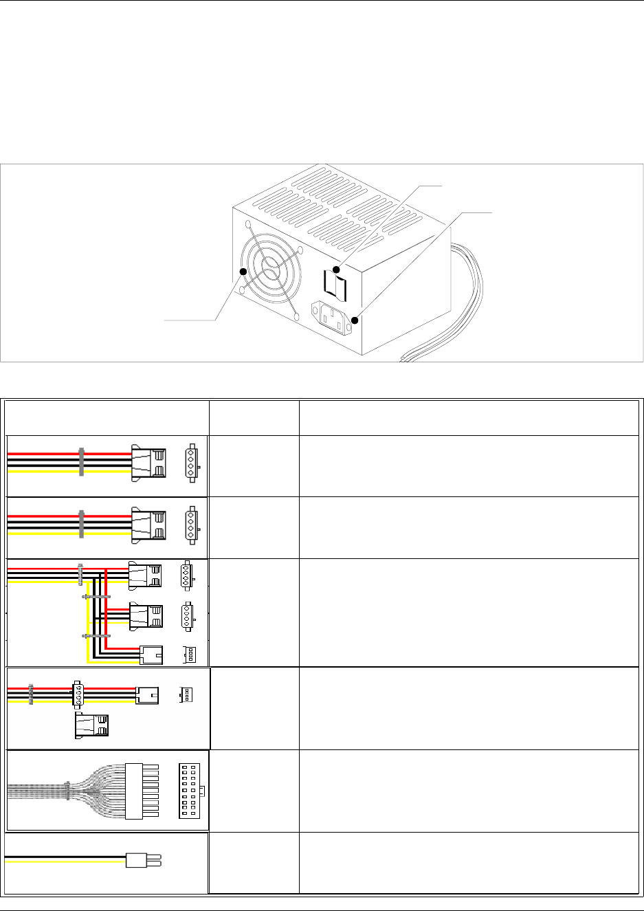
Chapter 1 Introduction to the Business Communications Manager Platform Hardware 65
Installation and Maintenance Guide
Platform Power Supply
The BCM200 and BCM400 (STD) base platforms use a switched power supply. Internal cabling
routes to the I/O card, media bay backplane and hard disk. External cabling extends to the line
power supply outlet. Figure 28 illustrates the standard platform power supply.
Figure 28 BCM200 and BCM400 (STD) platform power supply (rear view)
Figure 29 Standard power supply connectors
Rear view:
Standard power supply
Fan
AC power connector
On/Off switch
Connector Configuration for
Standard Sparkle Power Supply New Lengths Purpose and Notes
500mm to first,
+50mm to next,
+100mm to last
(total 650mm)
tie wrapped
every 5cm
480mm
430mm to first
(right angle) ,
+150mm to
next (total
580mm)
525mm MBM Back plane
MBM Back plane for BCM400, not required for BCM200
Hard disk cage, extra connectors to be tucked under the
hard disk
Reserved for future use
I/O Card
I/O Card
525mm
480mm
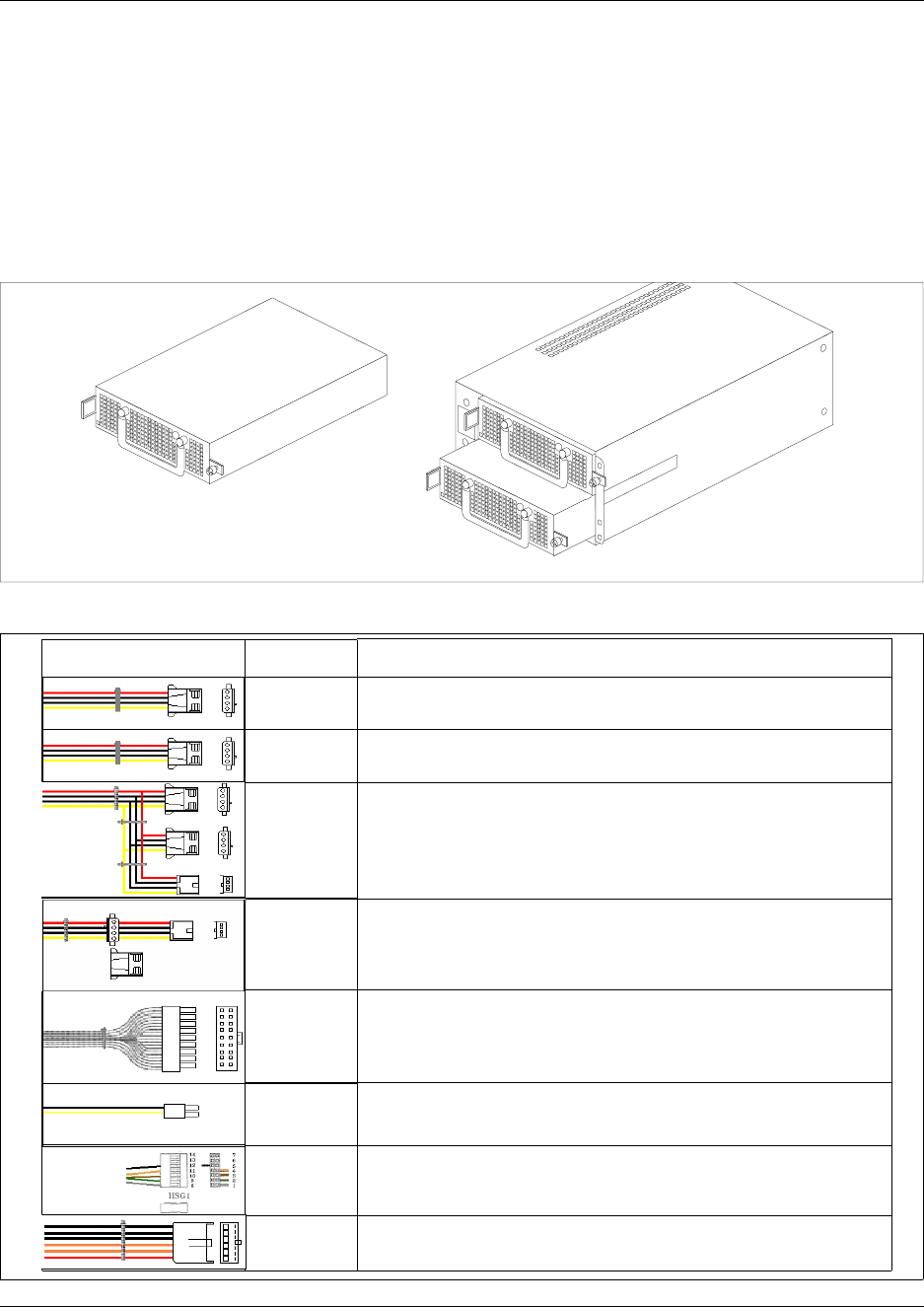
66 Chapter 1 Introduction to the Business Communications Manager Platform Hardware
P0993133 03
BCM400 redundant power supply
The redundant power supply (RPS) is available as a field replaceable unit (FRU). The redundant
power supply consists of two power supply modules and a power supply chassis. The power
supply modules are interchangeable and can be exchanged one at a time during power-on
conditions. Figure 30 illustrates the redundant power supply chassis and modules. Figure 31
provides details on the redundant power supply connectors.
Figure 30 BCM400 platform redundant power supply and modules
Figure 31 BCM400 Redundant power supply connectors
Power supply module
removed from the
redundant power supply
chassis
Power supply module
inserted in the
redundant power
supply chassis
Connector Configuration for
Redundant Sparkle Power Supply
Cable Lengths and
Markings
550mm (P2)
550mm (P3)
325mm to first
(P4), +50mm to
next (P5),
+100mm to last
(P6) (total 475mm)
340mm to first
(P7)(right angle)
,
+150mm to next
(P8) (total 490mm
)
515mm (P1)
515mm (P9)
515mm (PA)
300mm (PB)
Route to Media bay backplane 1: Tie any slack at
the connector (behind MBM)
Route to Media bay backplane 2: Tie any slack at
the connector (behind MBM)
To hard disk: Tie any slack at the power supply. Tuck
any loose connectors under hard disk cage.
Unused. Tie to the center of the hard disk cage.
Route to I/O card.
Route to I/O card.
Route to I/O card.
Unused
Purpose and Notes
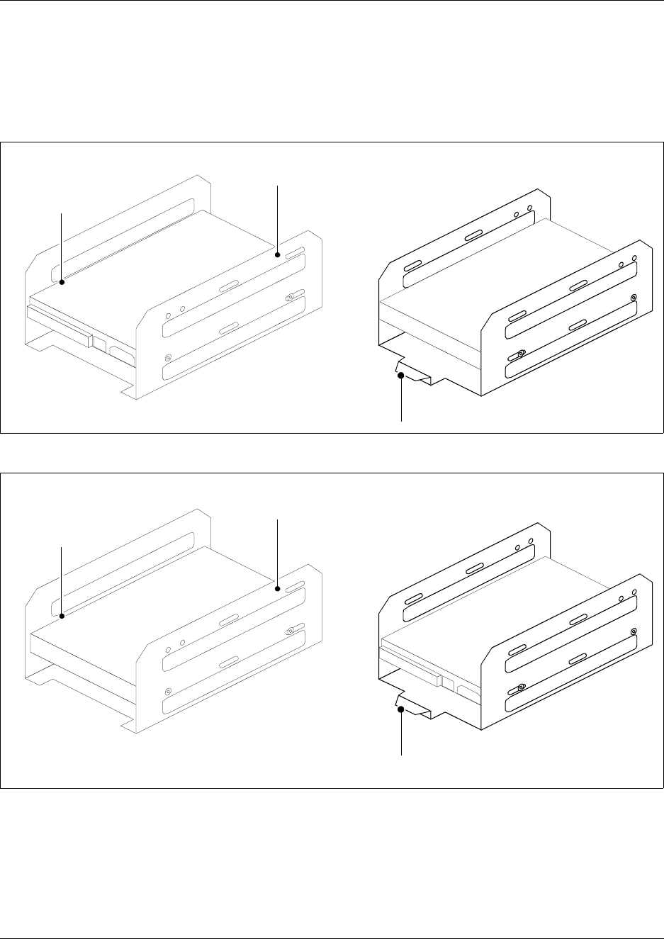
Chapter 1 Introduction to the Business Communications Manager Platform Hardware 67
Installation and Maintenance Guide
Hard Disk
The BCM200 and BCM400 standard configurations use a single hard disk (see Figure 32, Figure
33).
Figure 32 BCM200 standard hard disk and cage
Figure 33 BCM400 standard hard disk and cage
RAID upgrade kit
The BCM200, BCM400 standard configurations can be equipped with a RAID (redundant array of
independant disks) upgrade kit. The BCM200 and BCM400 RAID upgrade kits come with and
additional hard disk and RAID controller card. Your current disk is used as the primary, the other
Hard disk cage
BCM200 hard disk
cage - front view
Hard disk
BCM200 hard disk
cage - rear view
Hard disk cage lift tab
Hard disk cage
BCM400 hard disk
cage - front view
Hard disk
BCM400 hard disk
cage - rear view
Hard disk cage lift tab
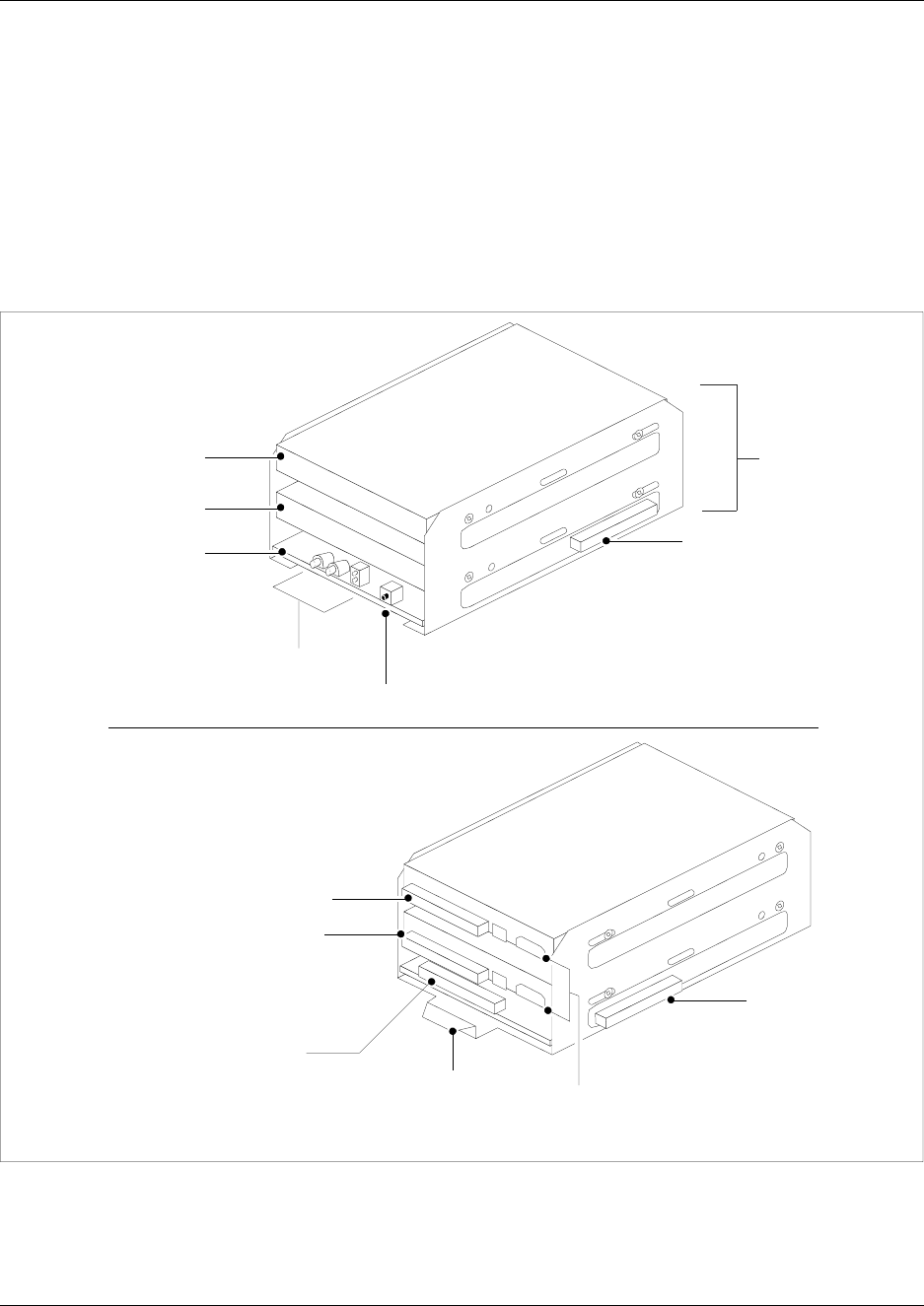
68 Chapter 1 Introduction to the Business Communications Manager Platform Hardware
P0993133 03
disk in the kit is the mirror disk. The information is written to both disks simultaneously. The dual
hard disk configuration provides RAID 1 fault tolerance capability.
The RAID card has three ribbon cable connectors. The hard disk connectors are mounted on the
right and left sides of the RAID controller card.
The third ribbon cable connection, mounted at the rear of the card, connects to the primary IDE
connector on the I/O card. Figure 34 illustrates the RAID components. For installation methods,
refer to Chapter 7, “Hard Disk Replacement Procedures’.
Figure 34 BCM200/400 2xHDD + RAID controller
Cooling Fan
Front view
Rear view
Power supply
connectors
RAID cage
Primary
Hard disk
Mirror Hard
disk
RAID card
status LEDs Reset button
Primary hard disk
ribbon cable
connector (Mirror
Hard disk
connector on
opposite side)
RAID
controller
card
Hard disk
cage lift tab
Mirror hard disk
ribbon cable
connector
IDE
connector
Mirror hard
disk RAID
connector
Primary hard
disk RAID
connector
*Note: BCM200 lift tab is on
opposite end.
*Note: Reverse RAID cage
installation for BCM200
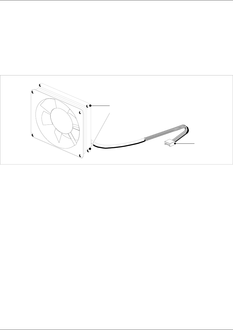
Chapter 1 Introduction to the Business Communications Manager Platform Hardware 69
Installation and Maintenance Guide
The BCM200/400 standard platforms use a single cooling fan. The BCM400 RFO configuration
uses two fans. The BCM200 cooling fan mounts on the rear of the platform base chassis.
The BCM400 cooling fan(s) mount on a removable panel at the rear of the platform base chassis.
For further information on the platform cooling fans, refer to Chapter 9, “Replace or Upgrade a
Power Supply’.
Figure 35 illustrates a cooling fan and connectors.
Figure 35 Cooling fan
Telephony Components
The telephony components perform call processing by connecting the telephones or peripheral
telephony equipment, such as fax machines, to the Public Switched Telephone Network (PSTN)
lines. They also process telephony information that has been received through an IP link.
• MSC — The Media Services Card (MSC) is a PCI card which performs call processing and
media processing of the voice channels. The Business Communications Manager 3.0 MSC
contains two PEC IIIs that provide additional voice channel processing for the MSC. Refer to
“Media services card (MSC)” on page 57.
• Media bay modules: The MBMs connect with external devices to implement various types of
voice trunks and stations. Install the MBMs in the media bay module bays in the BCM200,
BCM400 base platforms and the expansion unit. For further information on the media bay
modules, refer to Appendix , “Telephony Hardware Selection and Settings.
• Telephones and adapters — Business telephones and adapters connect to the media bay
modules installed in the Business Communications Manager system. Business
Communications Manager supports Norstar and Business Series Terminal sets, as well as
IP-based Nortel sets. Refer to Telephones and adapters on page 85 for a description of the
telephones that can be used with the system. The Nortel Networks i2002, i2004 IP telephones
and Nortel Networks i2050 Software Phone have separate installation and operations
documentation. Refer to the main index on your system CD.
I/O card fan
connector
Chassis mount
holes

70 Chapter 1 Introduction to the Business Communications Manager Platform Hardware
P0993133 03
The system also supports four types of cordless telephone systems: Companion, DECT, T7406
Business Series Terminal, and the Symbol NetVision and NetVision Data telephones.
Companion installation information is included in this guide and in the Programming
Operations Guide. Installation documentation for the other three systems is provided in
separate documentation for each system. Refer to “Telephones and adapters” on page 74 for
information about the handsets and the hardware they use to connect to the system.
This section describes the media bay module (MBM) telephony components and various types of
telephone equipment used with the Business Communications Manager system. Figure 36 points
to the sections that describe the modules and telephones that can be installed into the base function
tray.
The Business Communications Manager system is modular. You can increase the capacity of the
system by adding more telephony hardware components (media bay modules - MBMs). Each
Business Communications Manager allocates a maximum of six DS30 channels to the media bay
modules. The number of media bay modules that can be added to your system is determined by the
number of media bays that are open, combined with the number of DS30 channels each
component uses.
If your system requires many IP lines or trunks, you can reduce the number of DS30 channels that
are assigned to modules and increase the number of channels available to IP telephones. This is
known as a 3/5 DS30 channel split. In this case, you only have five DS30 channels available for
use by the media bay modules. Refer to “Understand DS30 numbers” on page 317 for more
information.
Refer to Chapter 4, “Install, remove or replace the Media Bay Modules,” on page 109 for details
about determining how many media bay modules can be installed in a system.
Warning: Changing the DS30 channel split
If you change the channel split from 2/6 (default) to 3/5 after the system is initialized, any
module set to DS30 channel 7 or requiring the use of channel 7 becomes inoperable.
If you change the channel split from a 3/5 split to a 2/6 split after the system is initialized,
all data is lost and all optional applications must be reinstalled and reconfigured.
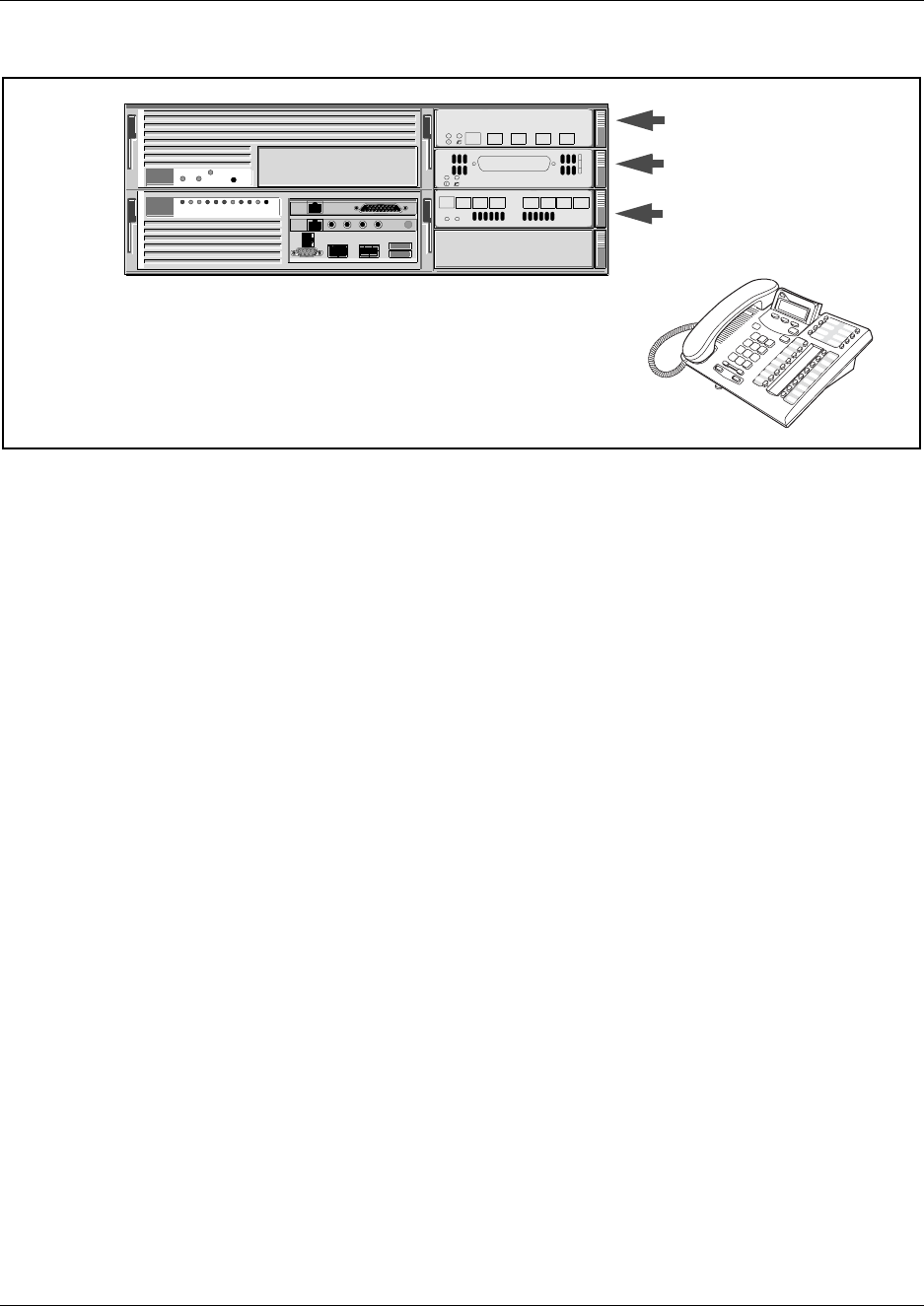
Chapter 1 Introduction to the Business Communications Manager Platform Hardware 71
Installation and Maintenance Guide
Figure 36 Telephony hardware components.
Media bay modules (MBMs)
The MBMs connect with external devices to implement various types of voice trunks and stations.
Install the MBMs in the media bay module bays in the BCM200, BCM400 base platforms and the
expansion unit. There are three types of media bay modules. Twelve media bay modules available
as optional equipment (as shown in Table 8).
“Trunk Media Bay Modules”
on page 74
“Station Media Bay Mod-
ules” on page 78
“Specialized Media Bay
Modules” on page 81
“Telephones and adapters”
on page 85
Refer to “Media Bay Module Availability by Region”
on page 303 and “Trunk Availability by Region” on
page 304 to determine which media bay modules
and which types of trunk lines are available in your
location.
CTM 4
1Aux 2 3 4
DSM 16+
1234 1234
StatusPower

72 Chapter 1 Introduction to the Business Communications Manager Platform Hardware
P0993133 03
Table 8 Media bay module list
Media bay modules are designed within a common casing, that include the following common
features:
• LEDs: All media bay modules have power and status LEDS.
• Power connections: located at the rear of the media bay module
• DIP switches: located at the rear of the media bay module
Module type Media bay module name Faceplate
acronym Reference
Trunk media bay
module Digital trunk interface DTM Digital trunk media bay
module on page 75
Caller ID trunk (CLID) 4 line trunk CTM 4 Caller ID trunk media bay
module on page 76
Caller ID trunk (CLID) 8 line trunk CTM 8 Caller ID trunk media bay
module on page 76
ISDN BRI S/T Interface ISDN BRI Basic rate interface media
bay module on page 77
Station media bay
module 16 digital station interface (DSI) double
density DSM 16+ Digital station media bay
module (DSM) on page 78
32 digital station interface (DSI) double
density DSM 32+ “Digital station media bay
module (DSM)” on page 78
Combination CTM4 x DSM16 4X16 “4X16 Media Bay Module”
on page 79
Analog Station Interface ASM 8 Analog station media bay
module on page 80
Specialized media
bay module DECT Base Station Module DECT8 Digital enhanced cordless
telecommunications
(DECT) media bay module
on page 81
DECT Base Station Module (u-law) DECT8 Digital enhanced cordless
telecommunications
(DECT) media bay module
on page 81
Fibre Expansion Module FEM 6 Fiber expansion media bay
module (FEM) on page 82
Digital Drop & Insert MUX DDI Mux Digital Drop & Insert MUX
(DDIM) on page 83
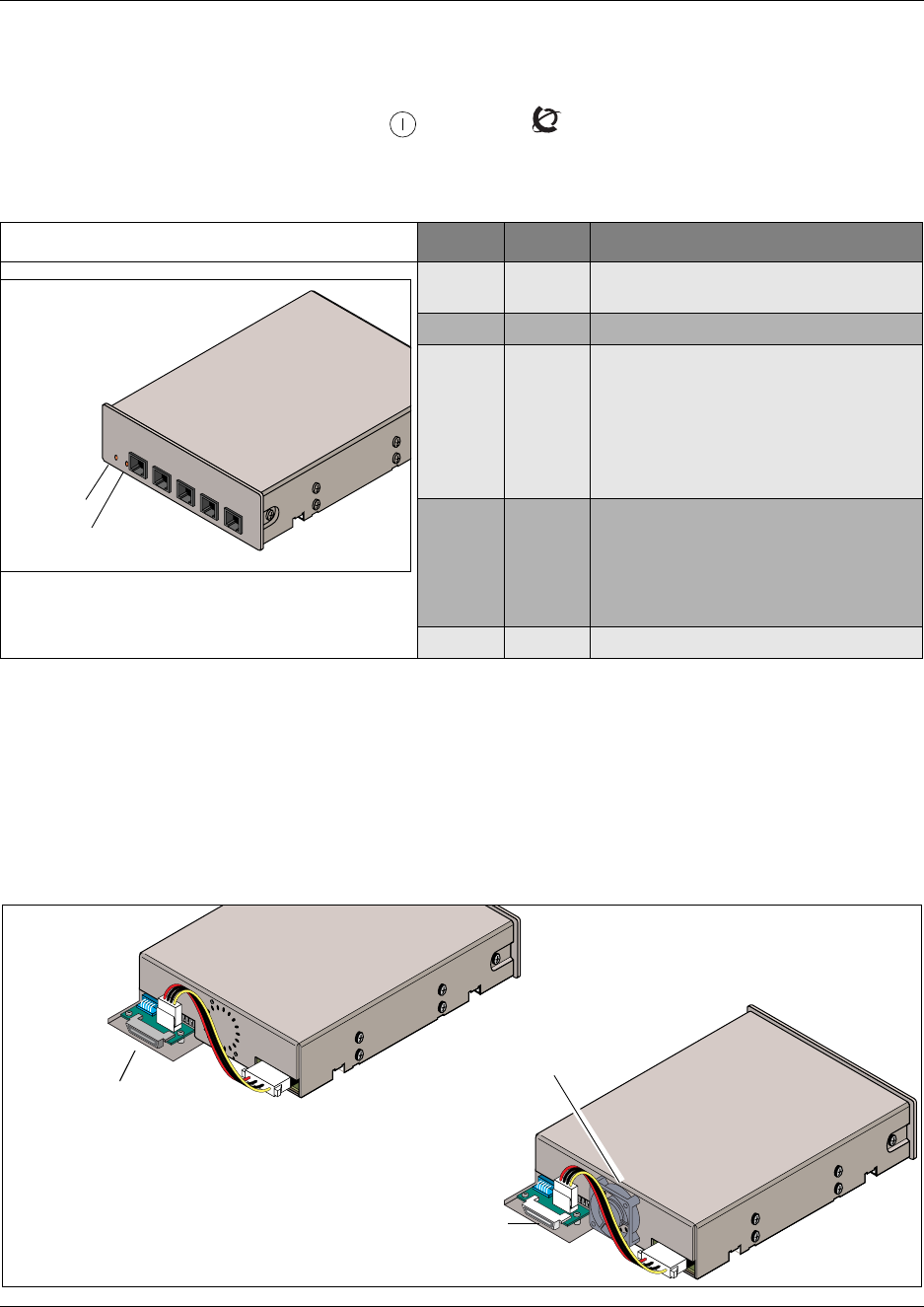
Chapter 1 Introduction to the Business Communications Manager Platform Hardware 73
Installation and Maintenance Guide
Media bay module LED indicators
Figure 37 shows the location of the (Power) and (Status) on a CTM. The power and status
LEDs are located in the same place on all modules. The figure describes the possible LED states.
Figure 37 Module Power and Status LED states
Media bay module power connections
The back of the modules have a single connector that provides a DS256 channel and power to the
module. These connectors plug into the media bay backplane on the base function tray or
expansion unit. Some modules also have a cooling fan that runs off the module power source.
Figure 38 shows the rear views of the two types of modules.
Figure 38 Rear of modules showing DS256 channel and power connectors
Power Status Description
Off Off No power applied to the module, or
failure of module power converter.
On Off FPGA not downloaded.
On Blinking Hardware is working, but there is an
operational problem such as:
• no DS256 link detected
• DS256 frame alignment lost
• bandwidth not allocated
• module is in maintenance state
Blinking Blinking Power is applied to module, but there is a
hardware problem such as:
• partial failure of power converter
• thermal overload
• fan failure
On On The module is read to operate.
CTM
Power LED
Status LED
DS256 and power
connector
DS256 and
power connector
Cooling fan
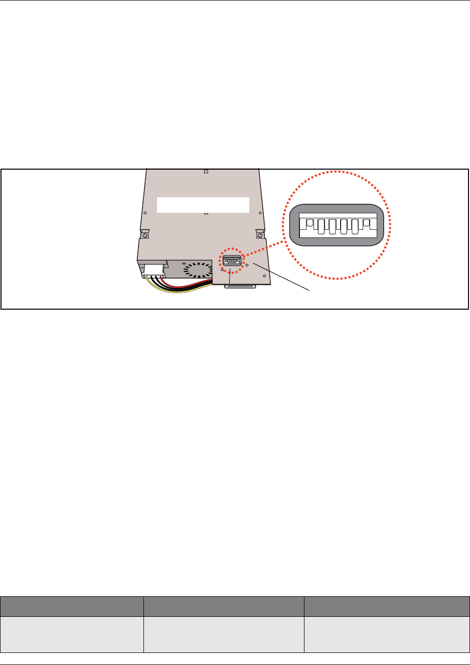
74 Chapter 1 Introduction to the Business Communications Manager Platform Hardware
P0993133 03
Media bay module DIP switches
The underside of most modules has a set of DIP switches that set the DS30 channel numbers and
offsets used by the module. Figure 39 shows the location of the DIP switches on the module. The
exception to this is the DECT module, where the switches are found on the rear of the module.
Refer to “Digital enhanced cordless telecommunications (DECT) media bay module” on page 81.
For more information about setting DIP switches, refer to Appendix , “Telephony Hardware
Selection and Settings.
Figure 39 Underside of module showing DIP switches
Trunk Media Bay Modules
You install the trunk media bay modules in the base function tray or the Business Communications
Manager expansion unit. The BCM200 holds a maximum of two media bay modules. The
BCM400 holds a maximum of four media bay modules. The expansion unit holds a maximum of
six media bay modules.
Trunk media bay modules connect telecommunications lines to the Business Communications
Manager system.
These are determined by:
• which lines are available from your telephone service provider
• what lines you require for the types of telephones you want to use
• budget considerations
Table 9 lists the types of trunk media bay modules that are available for the Business
Communications Manager system:
Table 9 Trunk media bay modules
Module type What it does Special notes
DTM
“Digital trunk media bay module”
Connects digital public switched
telephone lines to the Business
Communications Manager system.
Can connect to four types of lines: TI,
NA PRI, ETSI (in UK only), and Euro
PRI.
Rear of module DIP switches
Underside of module
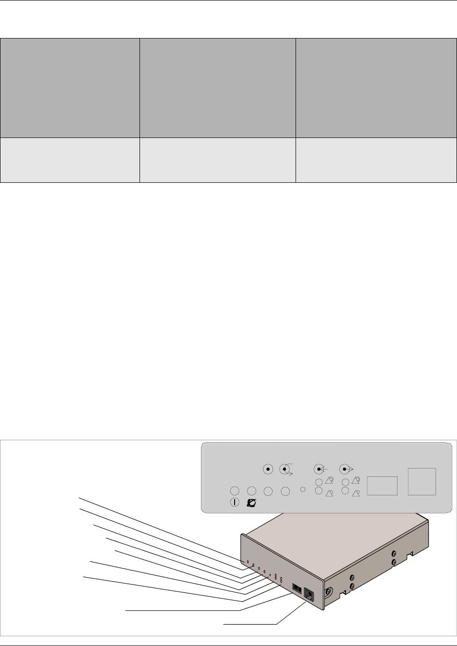
Chapter 1 Introduction to the Business Communications Manager Platform Hardware 75
Installation and Maintenance Guide
Digital trunk media bay module
The Digital Trunk media bay module (DTM) connects to standard digital PSTN T1/fT1, E1/fE1 or
PRI ISDN line using either a digital or PRI line. The DTM also supports DASS2, DPN22, Q.SIG
and MCDN over ISDN.
• On North American Business Communications Manager systems, the DTM connects to a T1
or PRI line. With a T1 line, you can add a maximum of 24 digital telephone lines. With a PRI
line, you can add a maximum of 23 digital telephone lines.
• On International Business Communications Manager systems, the DTM connects to an ETSI
or PRI digital line. With an ETSI or PRI line, you can add a maximum of 30 digital telephone
lines.
The front bezel of the DTM has a RJ48C connector that connects the DTM to the service provider
connection point. The faceplate also has a set of loopback connectors you can use to run loopback
tests. For details on loopback tests, refer to the Business Communications Manager 3.0
Programming Operations Guide. Figure 40 shows the DTM module interfaces.
Figure 40 Digital Trunk Interface Module (DTM) faceplate
CTM
“Caller ID trunk media bay
module”
CTM8
“Caller ID trunk media bay
module”
Connects a maximum of four analog
public switched telephone lines to the
Business Communications Manager
system.
Connects a maximum of eight analog
public switched telephone lines to the
Business Communications Manager
system.
Only available for North American
systems.
BRI
“Basic rate interface media bay
module”
Connects a maximum of four ISDN
BRI S/T interfaces Note: The DECT module contains the
equivalent of a BRI module and does
not require a separate module for trunk
line functions.
Table 9 Trunk media bay modules (Continued)
Power LED
Status LED
In Service LED
Loopback Test LED
Continuity Loopback
Receive LEDs
Transmit LEDs
Loopback
RJ48C digital telephone line connector
Front view DTM
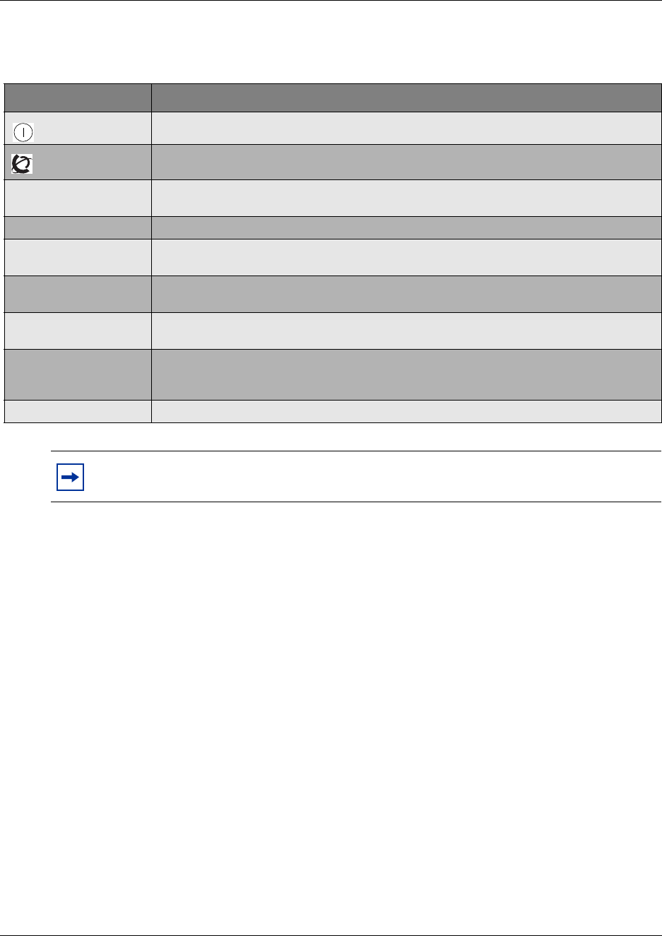
76 Chapter 1 Introduction to the Business Communications Manager Platform Hardware
P0993133 03
Table 10 provides a description of the function for each DTM LEDs.
Caller ID trunk media bay module
(North American systems only)
• The Caller ID Trunk media bay module (CTM) connects a maximum of four analog calling
line ID (CLID) interfaces to the Business Communications Manager system via four RJ11
jacks on the module face. These jacks are labeled: Line 1, Auxiliary, Line 2, Line 3, and Line
4. The auxiliary jack connects to Line 1.
• The CTM8 provides eight analog CLID interfaces to the Business Communications Manager
via eight RJ11 jacks on the module face. Each jacks also supports disconnect supervision.
There are also two auxiliary jacks on this module which connect to Line 1 and Line 5.
The auxiliary ports permit connection of a V.90 modem, FAX machine or single line analog
telephone. When the auxiliary device is active, the Business Communications Manager system
blocks the associated line. Conversely, when the line is active, the auxiliary port line is blocked.
When you connect a single line analog telephone to the auxiliary port, you can use it as an
emergency telephone because this line remains active if a power outage occurs.
Figure 41 shows a view of the front of the CTM and CTM8.
Table 10 DTM LED functions
LED label Function
(Power) On indicates that the DTM is receiving +5 volts.
(Status) On indicates there is data communication between the DTM and the MSC card.
In Service Flashing indicates that the T1, ETSI or PRI trunks are out of service because a loopback
test is running or the DTM is initializing.
Loopback On indicates a continuity loopback test is running.
Receive Alarm On indicates a problem with the received digital transmission. This half-duplex link does
not work.
Receive Error On indicates a small error as a result of degraded digital transmission. Possible causes
are an ohmic connection, water ingress, or too long a loop.
Transmit Alarm On indicates the DTM cannot transmit. The DTM sends an Alarm indication signal (AIS) to
the terminating switch. This half-duplex link does not work.
Transmit Error On indicates the DTM is sending a remote alarm indication (RAI) carrier failure alarm
(CFA) to the terminating switch. If the Transmit Alarm is not on, this error indicates a
far-end or cable problem.
All LEDS flashing All LEDs flashing continuously indicates that the DTM is initializing.
TIP: You can install a maximum of three DTM modules in the Business Communications
Manager system, depending on the available channels.
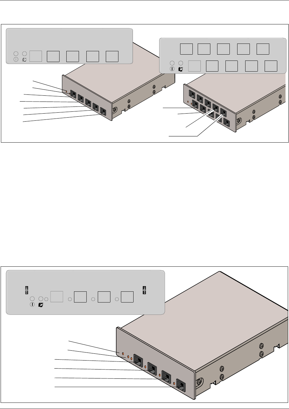
Chapter 1 Introduction to the Business Communications Manager Platform Hardware 77
Installation and Maintenance Guide
Figure 41 CTM and CTM8 LEDS and jacks
Basic rate interface media bay module
The Basic Rate Interface media bay module (ISDN BRI) module connects a maximum of four BRI
ISDN lines to the Business Communications Manager system. European systems use an S
interface. North American-based systems use a T interface with an external NTI line.
Each BRI ISDN line you connect adds two telephone lines to the Business Communications
Manager system. Therefore, each ISDN BRI adds a maximum of eight telephone lines to the
Business Communications Manager system via the four RJ48C jacks on the faceplate. You can
also use this module for dial backup or dial-on-demand services for WAN connections. The LEDs
beside each RJ-48C jack are on when the ISDN line is active. Figure 42 shows the BRI faceplate
LEDs and connections.
Figure 42 ISDN BRI media bay module LEDs and jacks
CTM
Power LED
Status LED
Line 1
Aux
Line 2
Line 3
Line 4 CTM8
Line 1
Auxiliary port
Auxiliary port
Line 5
CTM 4
1Aux 2 3 4
CTM 8
1Aux 2 3 4
87 6Aux5
Front View
Front view
Power LED
Status LED
Line 1
Line 2
Line 3
Line 4
ISDN BRI
1234

78 Chapter 1 Introduction to the Business Communications Manager Platform Hardware
P0993133 03
Station Media Bay Modules
Install the station media bay modules in the base function tray or the Business Communications
Manager expansion unit. Station media bay modules connect telephones and analog
telecommunication devices to the Business Communications Manager system.
Table 11 provides a list of the station modules available by region:
Digital station media bay module (DSM)
Three types of media bay modules support digital telephones on the Business Communications
Manager. This section describes the two DSM modules. Refer to Figure 43 on page 79.
• Digital Station media bay module (DSM 16+) supports 16 digital telephones. Set the full
double density (FDD) switch to enable the module to carry 16 extensions over a half DS30
channel. If required, install a second DSM 16+ and set the FDD switch to occupy the second
half of the DS30 channel (setting the FDD switch) to expand the number of extensions to 32.
• Digital Station media bay module (DSM 32+) supports 32 digital telephones through two
amphenol connectors. Set the full double density (FDD) switch to enable the module to carry
32 extensions over a half DS30 channel. If required, install a second DSM 32+ and set the
FDD switch to occupy the second half of the DS30 channel (setting the FDD switch) to
expand the number of extensions to 64.
• 4X16 supports 16 digital telephones and does not require a separate trunk module.
Refer to “4X16 Media Bay Module” on page 79.
Table 11 Station module regional availability
Module type What it does Availability
DSM 16+
“Digital station media bay module
(DSM)”
DSM 32+
“Digital station media bay module
(DSM)”
Connects a maximum of 16 digital
telephones
Connects a maximum of 32 digital
telephones to the Business
Communications Manager system.
4X16
Combination 4-line CTM and
DSM16 (4x16) Media Bay Module
“4X16 Media Bay Module”
Connects a maximum of four CLID lines
for a maximum of 16 digital telephones Only available for North American
systems. This module can be
combined with CTMs on the same
DS30 channel.
ASM8
“Analog station media bay
module”
Connects a maximum of eight analog
devices to the Business Communications
Manager system.
Only available for North American
systems.
Note: Devices that share a DS30 channel must be identical. Use two DSM 16+
modules in full double density mode on a single DS30 channel. Likewise, use two
DSM 32+ modules in full double density mode on a single DS30 channel.
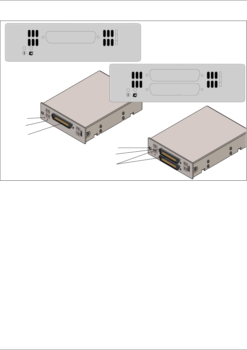
Chapter 1 Introduction to the Business Communications Manager Platform Hardware 79
Installation and Maintenance Guide
Figure 43 Faceplates of DSM 16+ and DSM 32+
4X16 Media Bay Module
(North American systems only)
The 4X16 provides both analog trunk connections and connections to digital telephones. The
module a CTM media bay module, with four analog lines, and a DSM 16-digital telephone media
bay module. Each of the four ports support Caller ID and disconnect supervision. An auxiliary port
beside Line 1 allows you to use an analog telephony device, such as a modem, fax or telephone, to
share the trunk.
Figure 44 shows a diagram of the 4X16. The 4X16 has one amphenol connector and five RJ11
connectors on the faceplate. For details on the 4X16 wiring, refer to Chapter 13, “Install Analog
Terminal Adapters,” on page 277.
DSM 16+
Power
Status
Amphenol
connector
Power
Status LED
Amphenol
connectors
DSM 16+
DSM 32+
DSM 32+
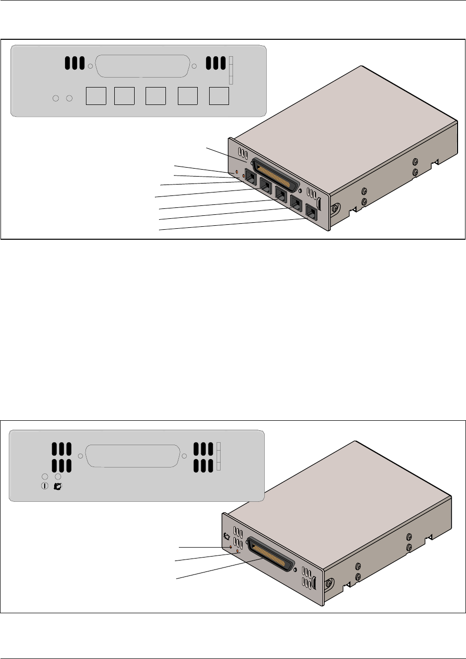
80 Chapter 1 Introduction to the Business Communications Manager Platform Hardware
P0993133 03
Figure 44 Faceplate of 4X16 module LEDS, connectors, and jacks
Analog station media bay module
(North American systems only)
The Analog Station media bay module (ASM 8) connects to eight analog telecommunication
devices. These devices can be standard analog telephones, cordless telephones, FAX machines,
answering machines, or modems. The maximum speed for a modem connection is 28.8 kbit/s.
Figure 45 shows a diagram of the ASM 8. The ASM 8 has one amphenol connector on the
faceplate. For details about wiring the ASM 8, refer to Chapter 13, “Install Analog Terminal
Adapters,” on page 277.
Figure 45 ASM 8 front view
DSM16 amphenol
connector
Power LED
Status LED
Line 1
Aux
Line 2
Line 3
Line 4
4X16
1Aux 2 3 4
StatusPower
Power
Status
Amphenol connector
ASM 8

Chapter 1 Introduction to the Business Communications Manager Platform Hardware 81
Installation and Maintenance Guide
Specialized Media Bay Modules
This section describes the modules that perform a specific job outside of the trunk and station
description. Refer to Table 12.
• The DECT (Digital Enhanced Cordless Telecommunications) module allows you to add
radio-based cordless communication devices to your Business Communications Manager in
areas where the DECT technology is available.
• The Fiber Expansion module (FEM), provides a fast way of upgrading from an existing
Norstar system simply by plugging in Norstar expansion modules to the FEM box.
Digital enhanced cordless telecommunications (DECT) media bay module
(region-specific application)
The Digital Enhanced Cordless Telecommunications (DECT) module allows radio-based cordless
handsets to access systems that are configured to accept the DECT profile. The module connects to
radio base stations, which receive and transmit signals to the handsets. Refer to “Mobility Services
by Region” on page 303 to determine the profiles that can use the DECT protocol.
Figure 46 shows a front view of the module. The DECT media bay module has eight RJ45 jacks
that connect to base stations deployed around the coverage area. Each DECT module supports four
ISDN lines and allows a maximum of eight simultaneous call paths back to the Business
Communications Manager. The DECT module LEDs indicate module power, status, run state and
base station power state. The figure also shows the location of the DIP switches on the DECT
module. Refer to “DECT switch settings” on page 343 for the switch settings required for the
module.
Table 12 Specialized modules
Module type What it does Special notes
DECT
“Digital enhanced
cordless
telecommunications
(DECT) media bay
module”
connects a maximum of eight radio base stations
which receives transmissions from registered
cordless handsets (a maximum of 32).
Refer to “Mobility Services by Region”
on page 303.
FEM
“Fiber expansion
media bay module
(FEM)”
connects a maximum of six Norstar expansion
modules The switches on the FEM are used to
turn fiber ports on and off. The FEM
does not work correctly if you set these
switches using the rules used for other
media bay modules.
DDIM
“Digital Drop & Insert
MUX (DDIM)”
enables a Business Communications Manager
system to share its connection to a Universal T1
network with a LAN
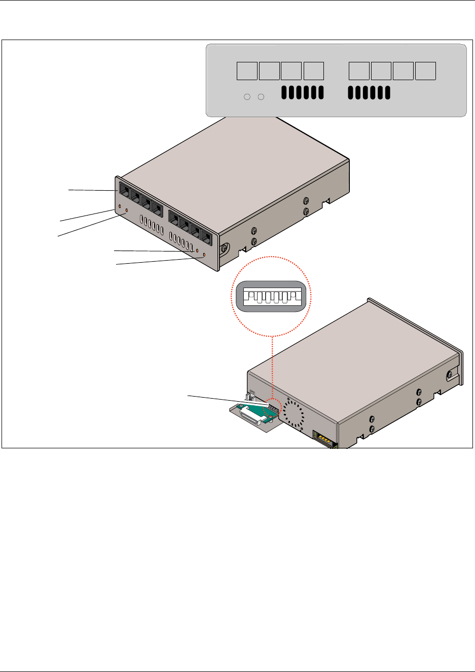
82 Chapter 1 Introduction to the Business Communications Manager Platform Hardware
P0993133 03
Figure 46 DECT faceplate with eight RJ45 connectors
Fiber expansion media bay module (FEM)
The Fiber Expansion media bay module (FEM) connects a maximum of six Norstar expansion
modules to the Business Communications Manager system. These connections provide a quick
way to upgrade a Norstar system to a Business Communications Manager system.
The front bezel of the FEM has six connectors. These connections are made using fiber cables
between the FEM module and the Norstar expansion modules. Beside each connector, an LED
lights when the fiber port is enabled.
Each RJ45 jack
can connect to
one base station
Power
Status
Run LED
Base station power
1234 1234
StatusPower
Rear view
DIP switches
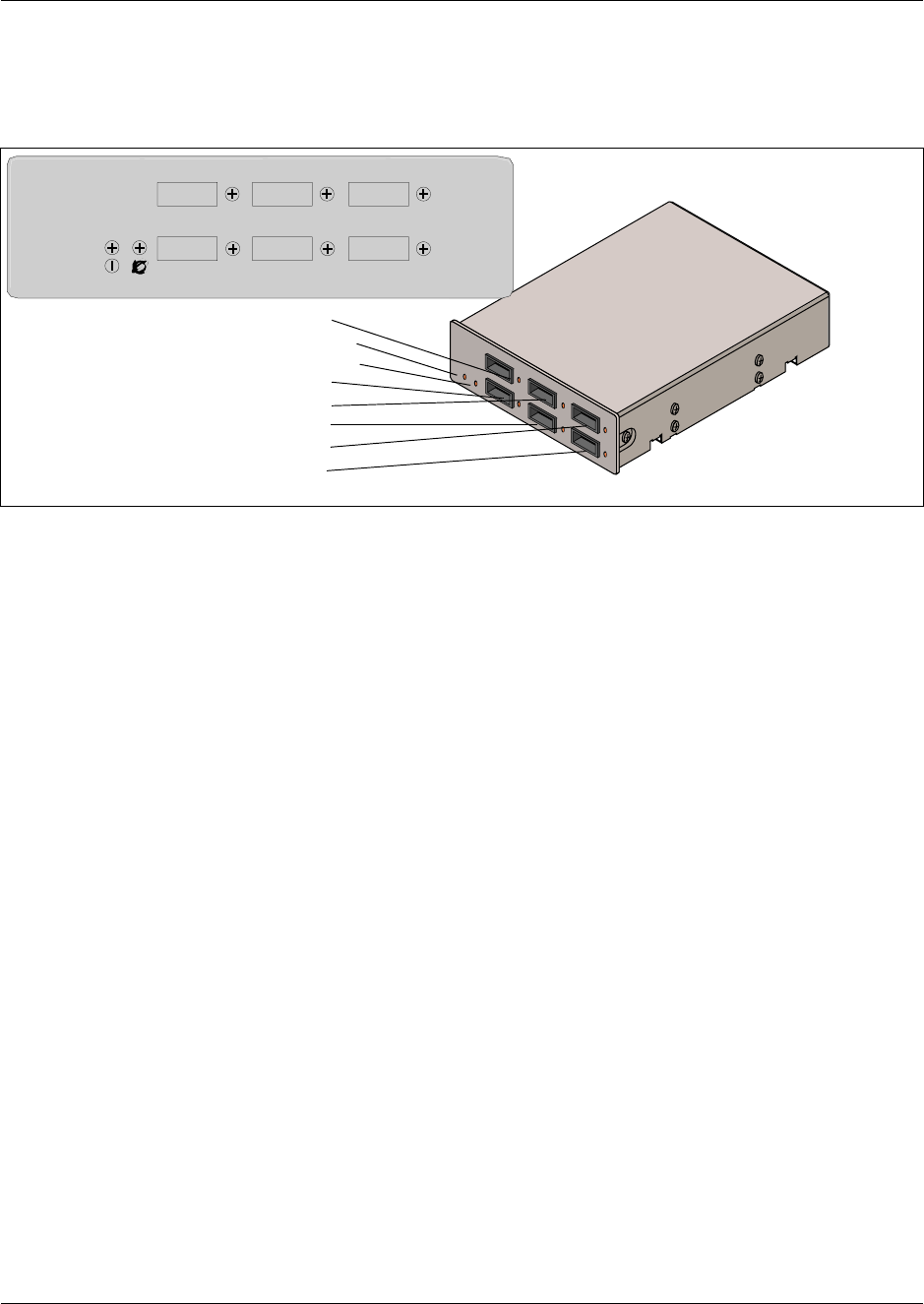
Chapter 1 Introduction to the Business Communications Manager Platform Hardware 83
Installation and Maintenance Guide
The module has port status LEDs beside each port, as well as the usual power and status LEDs.
Figure 47 shows the front of the FEM module. Each enabled port consumes one DS30 channel.
Figure 47 Fiber expansion media bay module (FEM) LEDs
Digital Drop & Insert MUX (DDIM)
The Digital Drop & Insert MUX (DDIM) module supports 1 x MUX T1 trunk with a user-defined
combination of voice and data channels. The DDI MUX enables a Business Communications
Manager system to share its connection to a Universal T1 network with a local area network
(LAN).
The DDI MUX:
• provides the functionality of a DTM media bay module (T1 digital lines only)
• splits the incoming T1 line so that some of the lines are used for voice traffic and some of the
lines are used for data traffic
• provides either the CSU (Channel Service Unit) or DSU (Data Service Unit) functionality to
support connections to data terminal equipment (DTE), such as a router or a bridge
• connects to network devices that support V.35 interfaces
• provides end-to-end transparent bit service
• supports loopbacks between the [Product Name (short)] and the internal Business
Communications Manager components, and between the [Product Name (short)] and digital
terminal equipment
Front view
Port 4
Power LED
Status LED
Port 1
Port 5
Port 2
Port 6
Port 3
456
321
FEM
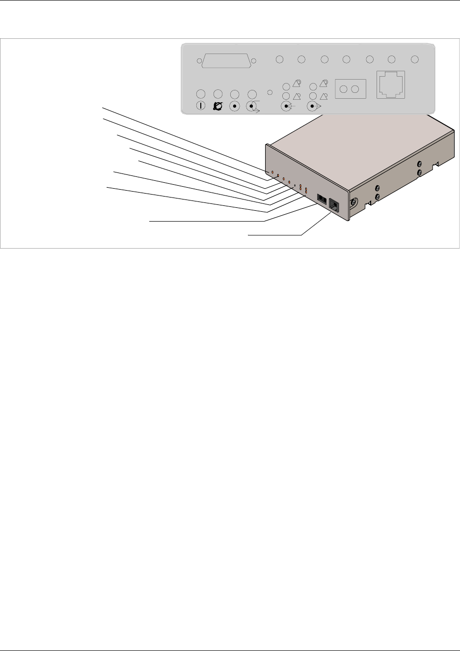
84 Chapter 1 Introduction to the Business Communications Manager Platform Hardware
P0993133 03
Figure 48 Digital Drop & Insert (DDIM) faceplate
Power LED
Status LED
In Service LED
Loopback Test LED
Continuity Loopback
Receive LEDs
Transmit LEDs
Loopback
RJ48C digital telephone line connector
TxD RxD RTS CTS DCD DSR TM

Chapter 1 Introduction to the Business Communications Manager Platform Hardware 85
Installation and Maintenance Guide
Telephones and adapters
The following telephones and devices can be used with the Business Communications Manager
system.
Business Series
Terminal T7100
— one-line display,
one memory button
without indicator.
T7000 (not shown)
(International only)
— four memory
buttons, without
display or
indicators.
Business Series
Terminal T7208 —
one-line display, eight
memory buttons with
indicators
Business Series
Terminal T7316
— two-line
display, three
display buttons,
16 memory
buttons with
indicators, eight
memory buttons
without indicators.
i2004 IP
telephone —
connects through
an internet link to
the Business
Communications
Manager.
Multi-line display,
six memory keys
with indicators. It
can be used to call
through VoIP or PBX lines.
Not shown: i2002 IP telephone and i2050 Software
Phone interface.
Norstar M7324
— two-line
display with
three display
buttons, 24
memory buttons
with indicators.
Options: two
CAP modules.
Norstar
M7324N (UK and Australia only) — same features.
Note: There is no Business Series Terminal
equivalent to this telephone.
•Central answering
position (CAP) (North
American systems
only) — connects to an
M7324 telephone and
provides 48 additional
memory buttons. You
need one Station
Auxiliary Power Supply (SAPS) for every M7324
telephone that has CAP modules.
•Central answering position (CAPN) (UK and
Australia only) — same features, connects to
M7324N telephones
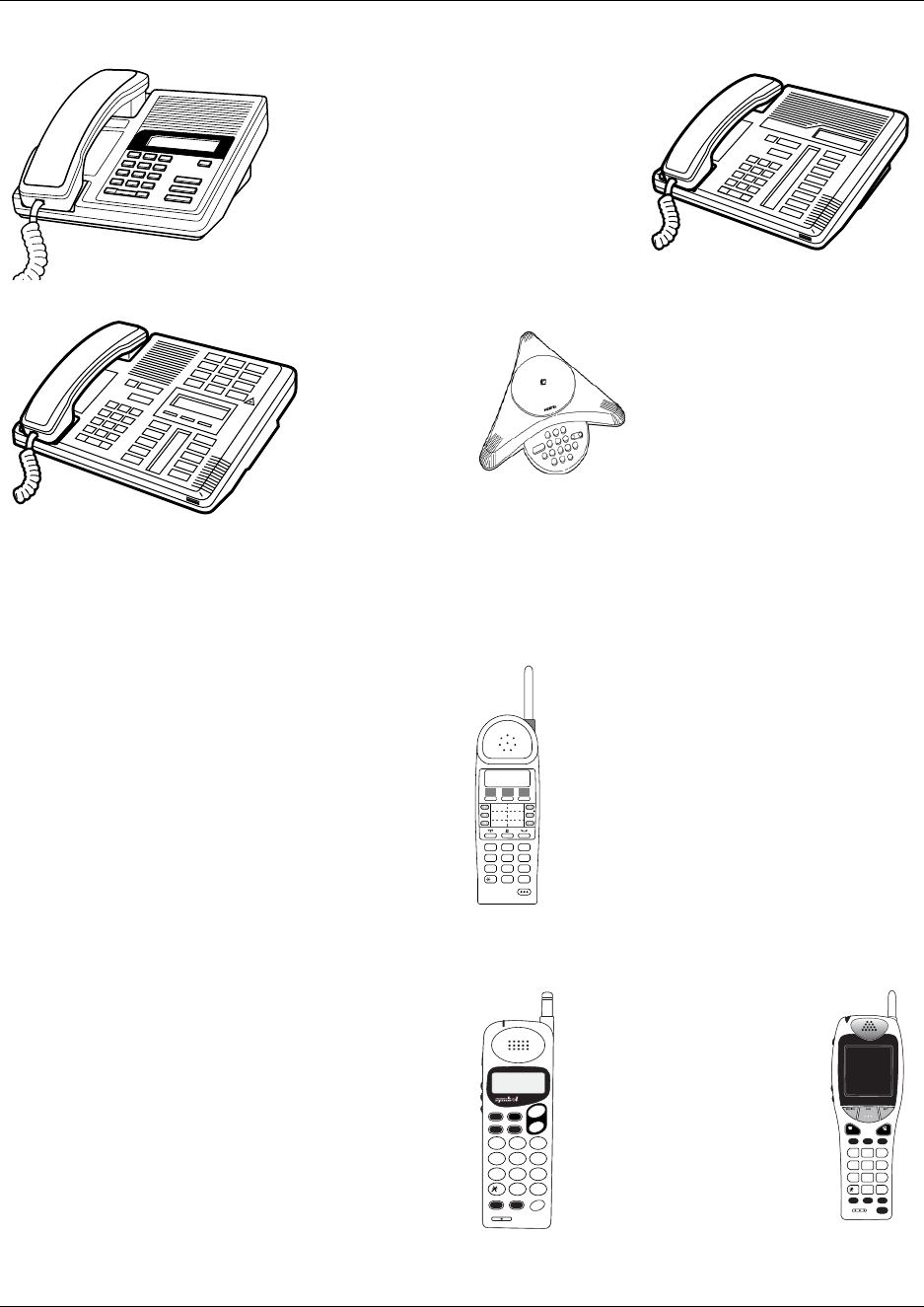
86 Chapter 1 Introduction to the Business Communications Manager Platform Hardware
P0993133 03
Norstar M7100 —
one-line display,
one memory
button, without
indicator.
Norstar M7100N
(UK and Australia
only) — same
features
Norstar M7208
— one-line
display, eight
memory buttons
with indicators.
Norstar M7208N
(UK and Australia
only) same
features
Norstar M7310
— two-line
display with
three display
buttons, 10
memory buttons
with indicators,
12 dual memory
buttons without
indicators.
Norstar M7310N (UK/Australia only) — same
features
Audio Conference Unit
(ACU)— provides large-room
audio conferencing. The
keypad provides many of the
set features of the basic Norstar
M-series telephones without
display or memory buttons.
This set comes with three
microphones. Installation
instructions are provided by the vendor.
Mobility options
Companion (region-specific) — provides twinning
capability between a stationary set and a wireless
mobile set. These handsets communicate through a
stationary base station, which is wired to a digital
station media bay module on the Business
Communications Manager. Depending on your
system configuration, you can have up to 64 sets
assigned to your system. For installation
instructions, refer to “Companion Hardware
Installation” on page 251.
Provides two-line display, but no line, memory or
display buttons. The handset accesses a restricted
set of system features.
T7406 Cordless Telephone system —
provides cordless mobility in a small
office environment. Each base station
supports three telephones. Function is
based on the T7316/M7310 telephone.
The base station connects to a digital
station media bay module on the system.
Provides six memory buttons with
indicators and a two-line display with
three display buttons.
For installation instructions, refer to the
T7406 Cordless Telephone Installation Guide.
DECT (region-specific) — provides cordless
access to the system through a DECT media bay
module. The cordless handsets can be twinned with
a stationary set, or configured to act as an
independent set. You can register up to 32 sets on a
module. Each Business Communications Manager
system, can support one DECT module.
Has display, but no line, display or memory buttons
and has access to a restricted list of system features.
For base station installation and handset registration
instructions, refer to the DECT Installation and
Maintenance Guide.
Symbol® NetVision and
NetVision Data
telephones — H.323+
based IP telephones
provide eMobility access
through a LAN/WAN
connection via a wireless
access point. A display
menu provides access to
user and call feature.
Provides multi-line display
capability, but no line, memory or display buttons.
ABC DEF
GHI JKL MNO
PQRS TUV WXYZ
1 2 3
4 5 6
7 8 9
0
#
FCTMENU
NAMERCL
STOCLR
SND
END
1 2
ABC
3
DEF
5
JKL
4
GHI
6
MNO
8
TUV
7
PQRS
9
WXYZ
0
OPR
<
#
>
HOLD
<>
FCT NAME HOLD
CLR STO RCL
MENU
21
ABC
3
DEF
54
JKLGHI
6
MNO
87
TUVPQRS
9
WXYZ
0
OPR
#
< >
END SND

Chapter 1 Introduction to the Business Communications Manager Platform Hardware 87
Installation and Maintenance Guide
Portable systems
The following sections describe the portable systems that are compatible with the Business
Communications Manager system, and the hardware components that are required.
Companion System Components
The Companion system allows portable access from a fixed line. The system consists of the
following hardware components:
• Companion base station — transmits and receives signals between the Business
Communications Manager system and portable handsets. You install the base stations on walls
or ceilings. Each base station provides radio coverage for a maximum of 32 cells.
•C3050 portable handset — The C3050 CT2 Plus portable handset is available in Canada
only. The Etiquette C3050 portable handset is available in the USA only. You can assign the
C3050 Portable Handset a separate telephone number or the same telephone number as a
desktop telephone. The C3050 supports basic features such as call forward, call transfer,
conferencing and visual message waiting indication.
•Remote power interconnect (RPI) Unit — The RPI provides remote power for base station
support. There are two types of RPIs: RPI-8 that supports a maximum of eight base stations
and RPI-16 that supports a maximum of 16 base stations.
Accessories
•Station auxiliary power supply (SAPS) —
provides power for the Business
Communications Manager central answering
position (CAP) module. Can also be used to
extend the loop length between a telephone or
terminal and the Business Communications
Manager system from 1,000 to 2,600 feet. You
must use a dedicated cable to connect the two
locations.
•Analog Terminal Adapter 2 (ATA 2) —
converts digital signals to analog signals to allow
communication with analog devices such as
FAX machines, modems and answering
machines. The ATA 2 supports a maximum
transmission rate of 28.8 kbit/s. With a single
line telephone, the ATA 2 supports a long loop
configuration. For more information, refer to
Chapter 13, “Install Analog Terminal Adapters,”
on page 277.
Note: Companion systems installed in the United States require a keycode to
activate the base stations. Refer to “The Companion Wireless System” on page
249.

88 Chapter 1 Introduction to the Business Communications Manager Platform Hardware
P0993133 03
DECT System Components
The DECT system allows the user to access calls and call features while away from their stationary
telephone. The following components combine with the DECT media bay module to provide this
service:
•Radio base station — provides the radio link between the Business Communications
Manager, through the DECT module, to the portable handsets.
•Portable handsets — communicate through radio base stations connected to the DECT
module.
DECT system installation and configuration information is contained in the Business
Communications Manager 3.0 DECT Installation and Maintenance Guide.
T7406 system components
The T7406 wireless system allows the user to access calls and call features while away from their
desk. The following components provide this service:
•Radio base station — provides the radio link between the Business Communications
Manager, through a station media bay module, to the portable handsets (three handsets per
base station).
•Portable handsets — based on T7316/M7310 functionality, including six line buttons and a
two-line display.
NetVision system components
The NetVision and NetVision Data telephones provide an internet telephone connection to the
Business Communications Manager. These eMobility wireless telephones are based on an
enhanced implementation of H.323, referred to as H.323+, and IEEE 802.11 protocol for wireless
LANs.
The NetVision system consists of the following components:
•Access point — provides the radio link between the NetVision telephones and an internet
connection. This hardware is ordered separately, and comes with complete installation
instructions. This component is not specific to Business Communications Manager.
Note:
The DECT cordless handset can be configured to act as a separate set, either providing a
point for target line calls, or with full call and receive capability, although some of the
features are not available.
The handset can also be twinned with desk sets to provide mobile coverage of one or more
stationary sets.

Chapter 1 Introduction to the Business Communications Manager Platform Hardware 89
Installation and Maintenance Guide
•Portable handset — communicates through the internet to the Business Communications
Manager. This handset is wireless. However, the access point through which it
communications connects to the internet, therefore, the handset appears as an IP telephone to
the Business Communications Manager.
•Handset administration — A Business Communications Manager running version 2.5,
Feature Pack 1 or newer software, provides a link to the NetVision Phone Administrator
(NVPA). This application, which is specific to the Business Communications Manager, resides
on your computer. It provides a set of handset options where you specify the features and
settings for each handset. This file is then uploaded by the handset through a serial cable from
your computer.
The Business Communications IP Telephony Configuration Guide describes how to integrate this
telephone into the Business Communications Manager system. Symbol provides a user manual
that describes the handset-based features and how they work. The NetVision Telephone Feature
Card, provided on your Business Communications Manager CD, describes how to use the
Business Communications Manager features that can be accessed by the handset.
Note:
The NetVision handsets can be configured to act as a stand-alone telephone, either
providing a point for target line calls, or with full call and receive capability, although
some of the features are not available. It can also be twinned with stationary telephones to
provide mobile coverage of one or more stationary telephones.
This handset has no memory buttons. Instead, a pre-programmed display menu provides
access to Business Communications Manager features.
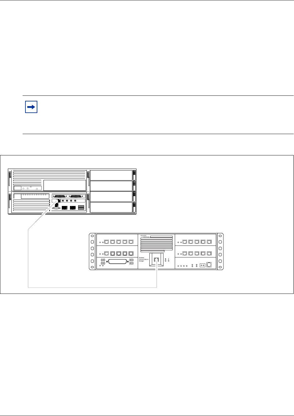
90 Chapter 1 Introduction to the Business Communications Manager Platform Hardware
P0993133 03
Business Communications Manager Expansion Unit
The Business Communications Manager expansion unit contains six additional bays for media bay
modules. The Business Communications Manager expansion unit is available for use only with the
BCM400.
The supplied DS256 cable is 5 m (16 ft.) long. Use of any other cable is not supported. The cable
connects into a DS256 port on the MSC of the base function tray, and into a DS256 port on the
center panel of the expansion unit. Refer to Figure 49.
Figure 49 Business communication manager DS256 connectors and expansion unit
Note: The number of modules that actually can be installed is determined by the number
of DS30 channels required by the modules and the number of channels available.
Refer to Chapter 3, “Install the Business Communications Manager & Expansion Unit
Platform Base Chassis,” on page 99.
Business Communications Manager expansion unit
NEEd
DS256 port
Business Communications Manager (BCM400)
DS256 port

91
Installation and Maintenance Guide
Chapter 2
Auxilliary Requirements and Installation Process
Overview
This chapter provides a description of the prerequisite computing platform and network
specifications to operate the Business Communications Manager Unified Manager software. This
chapter also provides summary of the installation process for the Business Communications
Manager, telephony components and Business Communications Manager expansion unit.
You require a personal computer to run the Business Communications Manager Unified Manager
application. Use the Unified Manager application to configure and manage the Business
Communications Manager system.
For administration purposes, you also require an network connection with the correct browser
setup.
Computer Specifications
These are the minimum computer specifications you need to run the Business Communications
Manager Unified Manager:
• 133 MHz Pentium CPU (or compatible)
• 64 MB RAM
• 10 MB disk space available
• screen resolution of 1024 x 768
• monitor large enough to support the screen resolution (suggested size: 17 inches)
• operating system: minimum — Windows 95/98, or NT, 2000 or the Millennium version
Browser Requirements
To use Business Communications Manager Unified Manager, you must have:
• Java Virtual Machine (JVM) 5.0 (build 5.0.0.3188 or greater)
one of the following web browsers:
— Netscape Communicator 4.5 or greater
— Microsoft Internet Explorer 4.0 or greater
Note: The ideal display setting for a monitor using Unified Manager is 1280 x 1024.
Unified Manager is a web-based application that runs off the Business Communications
Manager computer. Therefore, you take up minimal space on your computer and you can
run multiple applications on your computer. We recommend that you use Windows NT or
2000 to ensure optimal performance with the Unified Manager.

92 Chapter 2 Auxilliary Requirements and Installation Process Overview
P0993133 03
If you are using Netscape Communicator, set the following parameters:
• Enable Java: On
• Cached document comparison: Every time
If you are using Microsoft Internet Explorer, set the following parameters:
• Check for newer versions: Every visit to the page
• Java JIT compiler enabled: On
Preloading Java class Files On Your Workstation
To preload Java class files on your workstation:
1Open Unified Manager from your desktop.
The first window displays a number of functional buttons.
2Click the Install Client button.
3From the list, choose the link to the Java Class for the browser you are using (Internet Explorer
or Netscape Navigator).
Two more Java Class links appear.
4Click on the Java Class link that applies to your browser.
A download wizard appears.
5Follow the prompts on the wizard to download the Java Class files.
Optimizing Unified Manager Speed
The following are a number of suggestions about how to ensure you have the optimal connection
to your Unified Manager while you program or maintain your Business Communications System.
• Use the LAN, WAN, or serial port to connect to your computer and use the Unified Manager
to perform configuration.
• If you run multiple operations on your computer, we recommend that you use Windows NT or
2000 to ensure optimal performance with the Unified Manager.
• If your computer is using Windows 95/98, the interaction can be slower if you attempt to run
more than one application.

Chapter 2 Auxilliary Requirements and Installation Process Overview 93
Installation and Maintenance Guide
Installation Process Overview
Figure 50 provides an overview of the installation process. Use the overview information as a
quick reference to prepare the Business Communications Manager for installation. The overview
information provides the correct installation sequence.
Figure 50 Installation and initialization overview
Select the
media bay
modules you
require.
Install
the BCM and
(optional)
expansion
unit
The number of telephone lines and extensions you have determines the number and
type of media bay modules you need. For instructions about how to select the media
bay modules, refer to Chapter B, “Telephony Hardware Selection and Settings,” on
page 313.
The Business Communications Manager base function tray performs the main
computing tasks. It contains the telephony and data networking components.
If your system requires more than four media bay modules, you must install a
Business Communications Manager expansion unit.
For instructions about how to install the expansion unit, refer to Chapter B,
“Telephony Hardware Selection and Settings,” on page 313.
Set the
media bay
module
switches.
Before you install the media bay modules, you must set the switches on the back of
the modules to select the DS30 bus the modules will use to access lines and
extensions (DNs). For instructions about how to set the switches, refer to “Set Media
Bay Module Dip Switches” on page 322.
Continued on next page...
Install the
media bay
modules
After you have set the switches, install the media bay modules into the Business
Communications Manager or the expansion unit. For instructions about how to install
the media bay modules, refer to Chapter 4, “Install, remove or replace the Media Bay
Modules,” on page 109.
Power up
the base and
expansion
units
When you have the main hardware connected, start the system to ensure the first
level of hardware and software is working. For instructions about how to correctly
start the units, refer to Chapter 5, “Business Communications Manager System
Startup,” on page 127.
94 Chapter 2 Auxilliary Requirements and Installation Process Overview
P0993133 03
Connect the
telephony
components
The telephony components of the Business Communications Manager system
provide call processing and connection to the public telephone system. For
instructions about how to install telephones and components, refer to Chapter 13,
“Install Analog Terminal Adapters,” on page 277 and Chapter 14, “Install Optional
Telephony Equipment,” on page 287.
The Companion system provides wireless service between mobile sets and
stationary sets within the Business Communications Manager system.
The DECT module provides system connection for cordless handsets that can act
as mobile sets or as standalone sets.
These applications are region-based. Refer to “Mobility Services by Region” on
page 303.
For instructions about installing a Companion system, refer to Chapter 12, “Install
Companion or DECT Systems,” on page 249. The DECT module has a separate
installation and maintenance guide.
Connect
data
networking
equipment
The data networking components of the Business Communications Manager
system provide network connection to your local area network (LAN) and/or your
wide area network (WAN). For instructions about how to install the data
networking components, refer to “Connect the Data Networking Hardware” on
page 131.
Installation overview, continued...
Initialize
the system
Systems are shipped with a default IP and subnet mask. You must change these
settings to suit your system. Refer to “Initialize the System” on page 136, which
also describes how to set up your computer to access the Quick Start Wizard,
which you use to perform system configuration. Refer to the Business
Communications Manager 3.0 Programming Operations Guide for details about
the Quick Start Wizard.
Set up
system and set
configurations
Refer to the Business Communications Manager 3.0 Programming Operations
Guide to set up basic telephony and data configurations.
Refer to the separate application guides to set up optional applications such as call
management or voice over IP functions.
Install
optional
mobile
equipment
Chapter 2 Auxilliary Requirements and Installation Process Overview 95
Installation and Maintenance Guide
Installation Preparation Checklist
Before you install the base BCM platform base or expansion unit hardware, complete the
following actions.
• Determine the location for the Business Communications Manager (or expansion unit),
telephones, and other equipment based on spacing and electrical requirements. For more
information about spacing and electrical requirements, refer to the “Environment Checklist”
on page 95 and the “Electrical Requirements” on page 95.
• Order the required trunks from the central office.
• Check that all of the media bay modules are installed in the Business Communications
Manager or expansion unit.
• Ensure that you have all the equipment and supplies you require to install the system.
Environment Checklist
The installation area must be:
• minimum of 4 m (13 ft) from equipment such as photocopiers, electrical motors and other
equipment that produces electromagnetic, radio frequency and electrostatic interference
• within 1.5 m (5 ft.) of a three-wire grounded electrical outlet
• clean, free of traffic and excess dust, dry and well ventilated
• within the temperature ranges of 10°C and 40°C (50°F and 95°F)
• between 20% and 80% non-condensing relative humidity
• enough space and strength to support the Business Communications Manager
• minimum of 46 cm (18 in.) from the floor
Electrical Requirements
The following electrical requirements must be met:
• Power must be supplied from non-switched, unobstructed outlet within 1.5 m (5 ft.) of the
Business Communications Manager or expansion unit.
• The supplied power must be a dedicated 110 V - 120 V ac nominal (or 220 V - 230 V ac
nominal), 50/60 Hz, 15 A minimum service with a third wire safety ground. The third wire
safety ground provides shock protection and avoids electromagnetic interference.
Note: The installation area must be of sufficient height from the floor to prevent water
damage.
Danger: Risk of electric shock.
The safety of this product requires connection to an outlet with a third wire ground. Use
only with a three wire power cord and outlet.

96 Chapter 2 Auxilliary Requirements and Installation Process Overview
P0993133 03
The Business Communications Manager (or expansion unit) power cord is 1.5 m (5 ft) long. You
can connect the power cord to a power bar with a maximum length of 2 m (6.5 ft), including power
bar. You must use a power bar approved by an appropriate National Test Body, with a third wire
ground. Do not use an extension cord between the platform base chassis and the power bar, or
between the power bar and the electrical outlet.
The cable between the Business Communications Manager expansion unit and the Business
Communications Manager is supplied with the expansion unit. Do not use any other cables or
connectors.
Internal Wiring Requirements
This section describes the requirements for a digital loop and an analog loop within the system.
Digital Loop
The following parameters must be met for a digital loop:
• one, two, or three twisted-pair cable(s) per telephone
• dc loop resistance of less than 64 :
• cable length (0.5 mm or 24 AWG) less than 300 m (975 ft.)
• use of a station auxiliary power supply (SAPS) for loops 300 m (975 ft.) to 1200 m (3900 ft.).
In North America, the SAPS must be a CSA or UL approved Class 2 power source.
In Europe, the SAPS must be a Class II power source and CE marked.
• no bridge taps
Analog Loop
The following parameters must be met for an analog loop.
• maximum dc loop resistance of 208 :
• maximum cable length (0.5 mm or 24 AWG) of 1220 m (4000 ft.)
Caution: Check ground connections.
Ensure that the electrical ground connections of the power utility, telephone lines and
internal metal water pipe system, if present, are connected together. If these ground
connections are not connected together, contact the appropriate electrical inspection
authority. Do not try to make the connections yourself.

Chapter 2 Auxilliary Requirements and Installation Process Overview 97
Installation and Maintenance Guide
System Equipment and Supplies
Use the checklists in this section to ensure you have all the required equipment.
Basic hardware
The Business Communications Manager system consists of some combination of the following
hardware:
• Business Communications Manager system
• Business Communications Manager expansion unit
• media bay modules
• telephones
• cabling for connections between hardware units
You can place a maximum of two media bay modules in the BCM200 and four media bay modules
in the BCM400 platform base chassis. Install and use an expansion unit (only with a BCM400
system) if you require more than four media bay modules.
Optional equipment
The following equipment can be added to the system to support specific requirements beyond the
BCM platform base hardware:
• Station auxiliary power supply (SAPS)
• Central answering position (CAP or CAPN) module to as many as five M7324 telephones in
the system
• Business Communications Manager Analog Terminal Adapter 2
(ATA 2) if connecting analog equipment to a digital media bay station module
• Uninterruptable power supply (UPS) as a standalone device
• Analog emergency telephone
• WAN card field replaceable unit (FRU) if the Business Communications Manager base system
requires connection to a WAN. There are two WAN card types available. The North America
version has a T1 and v.35 interface. The international version has a x.21 and v.35 interface.
• Countries outside of North America must order separately, a power cord that conforms to their
specific requirements or standards. All North American base and expansion systems are
equipped with a North American power cord.

98 Chapter 2 Auxilliary Requirements and Installation Process Overview
P0993133 03
Companion equipment
If you are installing a Companion system, check that you have the following hardware.
Optional Companion equipment
• clip holster
• leather glove
• rugged protector
• headset – earbud (battery not included)
• headset – over the head (battery not included)
Other cordless systems
The DECT cordless system, T7406 cordless handset, and Symbol NetVision wireless IP handsets
all have installation documentation specific to the installation of base stations and registration of
the handsets to the Business Communications Manager.
DECT Equipment
If you are installing a DECT system, check that you have the following hardware.
• DECT module
• base station kit
• handsets and rechargers
Equipment for installing the platform base chassis
For the installation, you need the following equipment:
• rack mounting bracket
• four rubber feet
• Phillips screwdriver #2
• flat blade screwdriver
• pliers
• antistatic grounding strap
• connecting tool
• surge protector (recommended)
• cables, 25-pair cable with amphenol connectors
C3050 CT2 Plus (Canada)
• base station kit
• handsets (C3050)
• battery packs (NiCad 600
mAh)
• high-capacity battery charger
C3050 Etiquette (USA)
• base station kit
• handsets (C3050)
• battery packs (NiCad 600 mAh)
• high-capacity battery charger
• UTAM software keycode for base station activation
99
Business Communication Manager 3.0 Installation and Maintenance Guide
Chapter 3
Install the Business Communications Manager &
Expansion Unit Platform Base Chassis
This chapter describes how to install the Business Communications Manager platform base chassis
and expansion unit in your physical environment.
Install the Platform Base Chassis in a Rack
The Business Communications Manager platform base chassis fits into a standard 19-inch
equipment rack. You can install the platform base chassis in the same rack as your other
networking and telecommunications equipment.
Attach the rack mounting brackets
1Place the Business Communications Manager platform base chassis on a flat, clean surface.
2Align the screw holes between the Business Communications Manager platform base chassis
and the right rack mounting bracket.
3Fasten the bracket to the Business Communications Manager platform base chassis using four
screws.
4Align the screw holes between the Business Communications Manager platform base chassis
and the left rack mounting bracket.
5Fasten the bracket to the platform base chassis using four screws. Refer to Figure 52.
Caution: When installing the Business Communications Manager platform base chassis
in a rack, do not stack units directly on top of one another in the rack.
Fasten each unit to the rack with the appropriate mounting brackets. Mounting brackets
cannot support multiple units.
Refer to “Environment Checklist” on page 95 for acceptable environmental conditions
before selecting a location for the Business Communications Manager platform base
chassis.
Caution: For desk mount installations, do not place anything directly on top of the
Business Communications Manager base platform chassis.
Caution: Only use the screws supplied with the rack mounting bracket. Do not replace
screws. Other screws can damage the Business Communications Manager platform base
chassis.
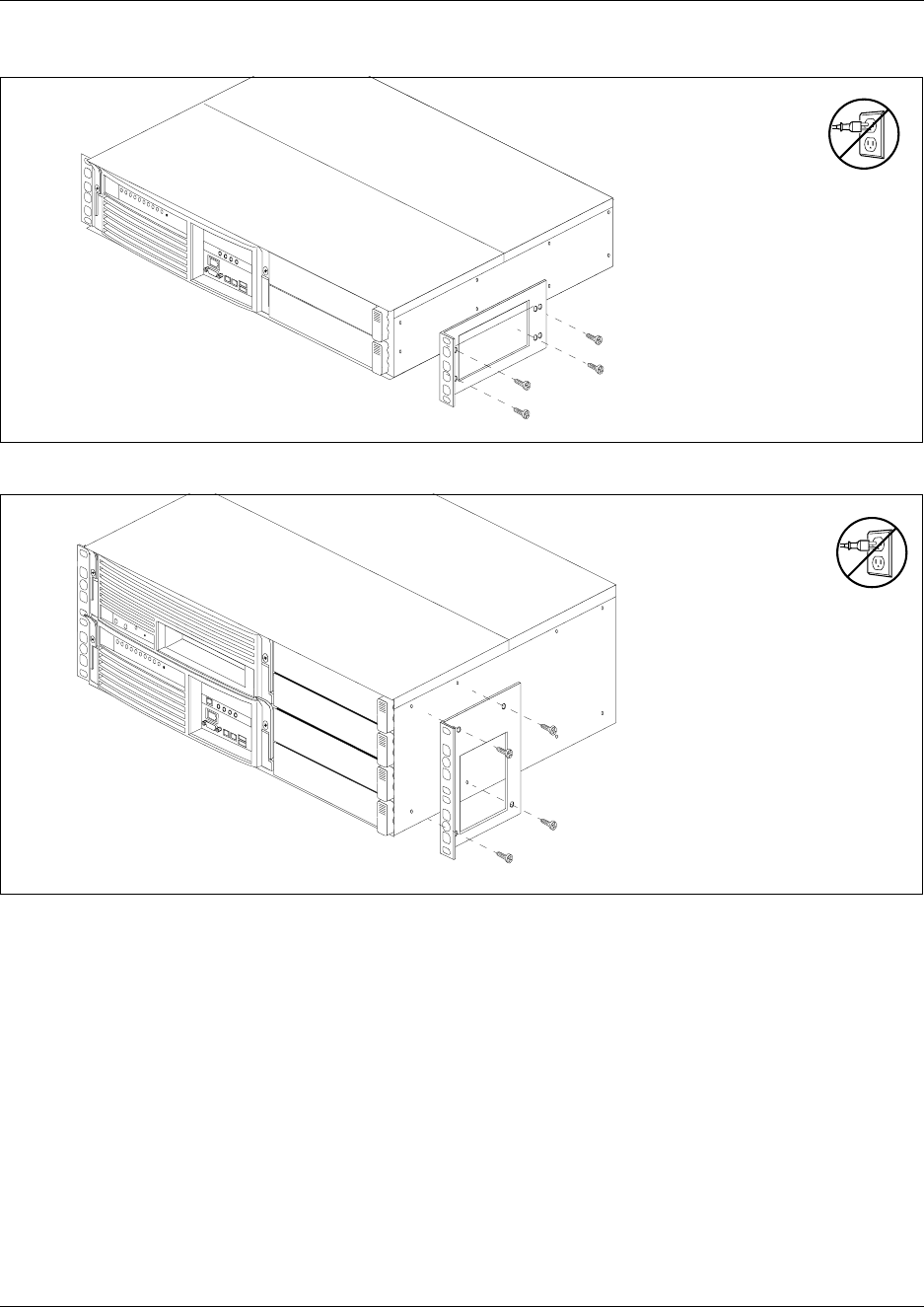
100 Chapter 3 Install the Business Communications Manager & Expansion Unit Platform Base Chassis
P0993133 03
Figure 51 Attach the rack mount bracket to the BCM200 chassis
Figure 52 Attach the rack mount bracket to the BCM400 chassis
Mount the platform base chassis into an equipment rack
Use the procedure in this section to install the Business Communications Manager platform base
chassis in an equipment rack.
1Determine the location in the rack where you want to install the platform base chassis.
2Position the unit in the rack. Have an assistant hold the platform base chassis.
3Align the holes in the rack mounting bracket with the holes in the equipment rack rails.
4Fasten the rack mounting brackets to the rack using four screws (supplied).
Refer to Figure 53.
Install rack mount
bracket screws
Install rack mount
bracket screws
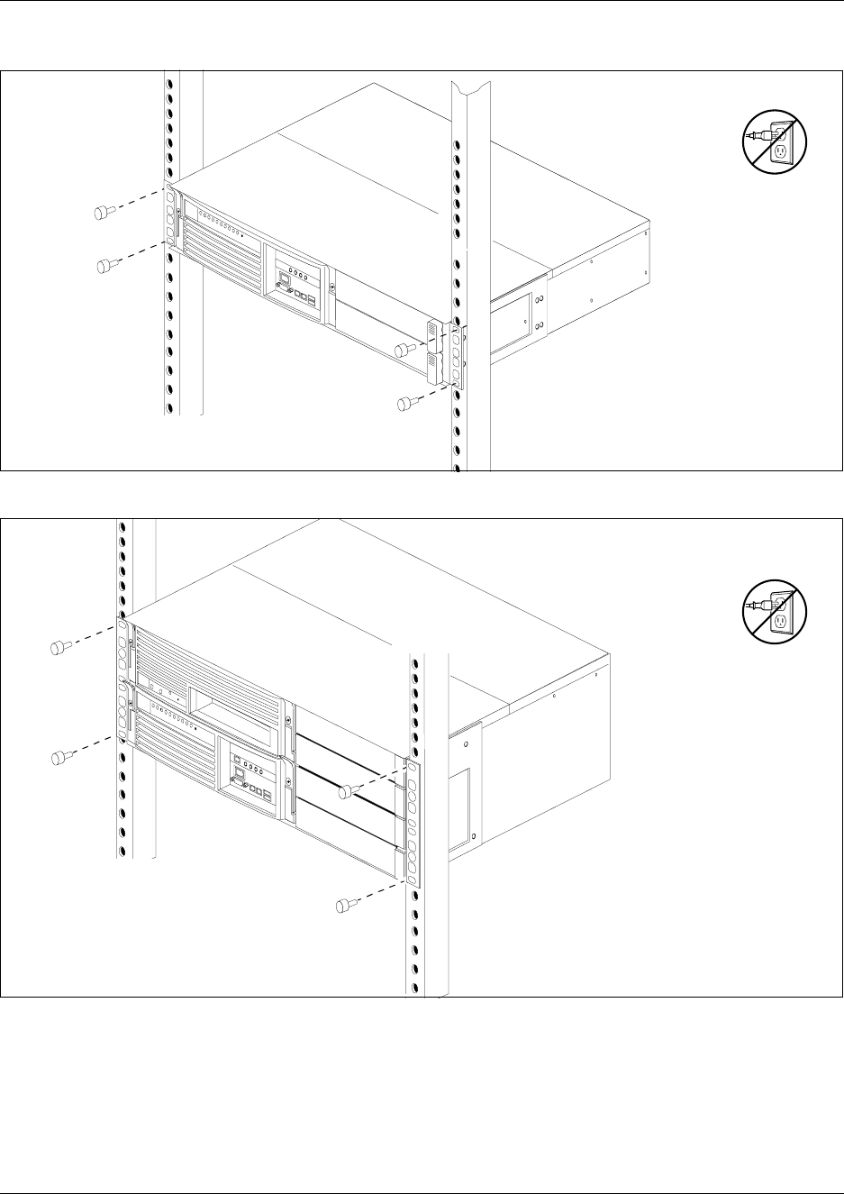
Chapter 3 Install the Business Communications Manager & Expansion Unit Platform Base Chassis 101
Business Communication Manager 3.0 Installation and Maintenance Guide
Figure 53 Fasten the BCM200 platform base chassis to an equipment rack
Figure 54 Fasten the BCM400 platform base chassis to an equipment rack
5This procedure is complete.

102 Chapter 3 Install the Business Communications Manager & Expansion Unit Platform Base Chassis
P0993133 03
Install the Platform Base Chassis on the Wall
This procedure describes how to mount the BCM200 or BCM400 platform base chassis to a wall.
To mount the Business Communications Manager platform base chassis on the wall, you need:
• a wall-mount bracket kit NTAB3422
• four #10 x 2.5 cm (#10 x 1 in.) round head wood screws
• a plywood backboard 2 cm (3/4 in.) thick
1Mark the location of the plywood backboard on the wall using a pencil. Use a ruler and
bubble-level to check that the plywood backboard is level with respect to the wall.
2Mount the plywood backboard securely to the wall.
3Mark the location of the wall mount bracket holes on the plywood backboard.
aUse the wall mount bracket as a template.
bUse a bubble-level to check that the wall mount bracket is level with respect to the
plywood backboard.
4Install four #10 x 2.5 cm (#10 x 1 in.) round-head wood screws in the backboard (supplied).
aDo not tighten the screws heads against the backboard. Leave approximately 0.5 cm (0.25
in.) of the screw exposed from the backboard.
bPerform a trial-installation of the wall mount bracket on the plywood backboard. Ensure
the wood screw heads seat in the wall mount bracket slots. If the wood screws are too
tight, loosen until the screw heads fit fully in the slots.
cEnsure that the wall mount bracket is level with respect to the plywood backboard.
dRemove the wall mount bracket.
5Align the screw holes on one side of the Business Communications Manager platform base
chassis with the wall mounting bracket.
Caution: Refer to “Environment Checklist” on page 95 for acceptable
environmental conditions before selecting a location for the Business
Communications Manager platform base chassis.
Note: Nortel Networks does not recommended use of the rack-mount brackets for wall
mount applications.
Note: The bracket suspends the Business Communications Manager platform base
chassis on the wall. Consider the direction you want the media bay modules to face, left or
right, when you choose the side to install the bracket.
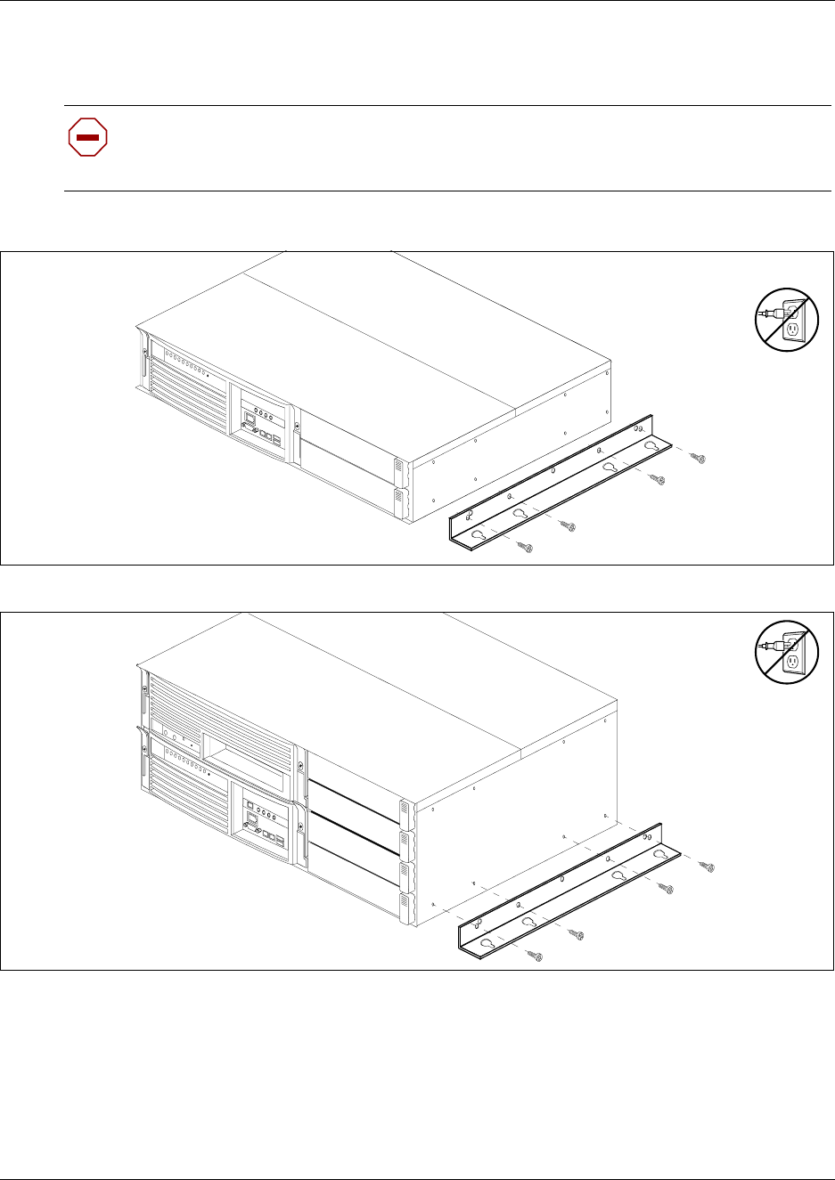
Chapter 3 Install the Business Communications Manager & Expansion Unit Platform Base Chassis 103
Business Communication Manager 3.0 Installation and Maintenance Guide
6Fasten the wall mount brackets securely to the Business Communications Manager platform
base chassis using the screws provided. Refer to Figure 56.
Figure 55 Attach the wall-mount brackets to the BCM200 platform base chassis
Figure 56 Attach the wall-mount brackets to the BCM400 platform base chassis
7Hang the Business Communications Manager platform base chassis on the backboard screws.
Make sure the platform base chassis is level. Ensure the wood screwheads seat fully into the
wall mount bracket slots.
8Tighten the wood screws against the wall mount bracket.
9This procedure is complete.
Caution: Use only the screws supplied with the wall mounting bracket. Do not replace
screws. Other screws can damage the Business Communications Manager platform base
chassis.
Install wall mount
bracket screws
Install wall mount
bracket screws
104 Chapter 3 Install the Business Communications Manager & Expansion Unit Platform Base Chassis
P0993133 03
Install the Platform Base Chassis on a Flat Surface
Use this procedure to install the Business Communications Manager platform base chassis on any
flat surface that can safely support the weight of the unit.
To install the Business Communications Manager platform base chassis on a table or shelf:
1Attach four rubber feet to the corners on the bottom of the platform base chassis.
2Position the platform base chassis on the table or shelf. Make sure you leave enough space
around the unit for ventilation and access to the cables and media bay modules.
3This procedure is complete.
Install the Expansion Unit into a Rack
This section describes how to install the Business Communications Manager expansion unit.
The Business Communications Manager expansion unit must be installed close enough to the
Business Communications Manager that the 5 m (16 ft) cable between the two units can be
connected to the Business Communications Manager without stress on the cable. The expansion
unit has the same environmental and electrical requirements as the Business Communications
Manager. For more information about these requirements, refer to “Installation Preparation
Checklist” on page 95.
The Business Communications Manager expansion unit fits into a standard 19-inch equipment
rack. Install the expansion unit in the same rack as the Business Communications Manager
platform base chassis.
Attach the mounting brackets to the Expansion Unit
You must install two rack brackets on the expansion unit to allow you to install the unit into the
equipment rack. These brackets are supplied with the expansion unit.
1Place the Business Communications Manager expansion unit on a table.
Caution: Refer to “Environment Checklist” on page 95 for acceptable environmental
conditions before selecting a location for the Business Communications Manager platform
base chassis.
Caution: Possible damage to the platform base chassis. Do not place anything directly on
top of the Business Communications Manager base platform chassis.
Caution: When installing the Business Communications Manager expansion unit in a
rack, do not stack units directly on top of one another. Fasten each unit to the rack with the
separate mounting brackets.
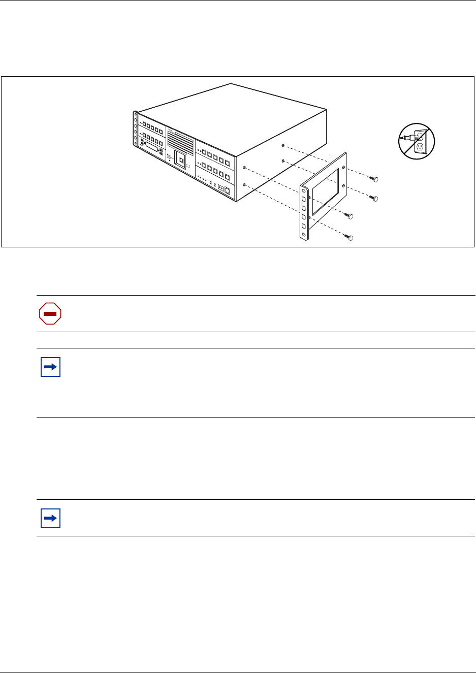
Chapter 3 Install the Business Communications Manager & Expansion Unit Platform Base Chassis 105
Business Communication Manager 3.0 Installation and Maintenance Guide
2Align the screw holes between the expansion unit and the right rack mounting bracket. Refer
to Figure 57.
Figure 57 Attach the rack mounting bracket to the expansion unit
3Fasten the bracket to the expansion unit using four screws.
4Repeat steps 2 and 3 on the other side, with second bracket.
Mount the Expansion Unit to the rack
The mounting brackets you attached to the expansion unit correspond with mounting holes located
on the equipment rack.
1Determine the location in the rack you want to install the Business Communications Manager
expansion unit.
2Position the expansion unit in the rack. Refer to Figure 58.
3Align the holes in the rack mounting bracket with the holes in the rails.
4Fasten the rack mounting brackets to the equipment rack using four screws.
Caution: Use only the screws that came with the bracket. Using other screws can damage
the equipment.
Note: Rack mount bracket
The expansion unit rack mount bracket has an additional set of holes that allows you to
install the brackets so that the expansion unit sits flush with the Business Communications
Manager chassis in an equipment rack.
Note: You must supply your own screws to attach the expansion unit to the rack.
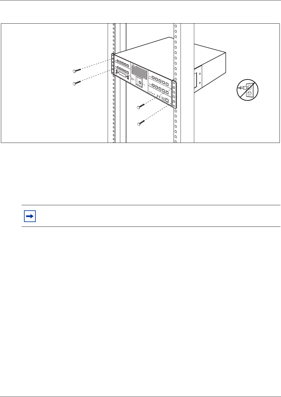
106 Chapter 3 Install the Business Communications Manager & Expansion Unit Platform Base Chassis
P0993133 03
Figure 58 Fasten the expansion unit to the equipment rack
Install the Expansion Unit on a Flat Surface
You can install the Business Communications Manager expansion unit on any flat surface that can
support the weight of the unit, and which is within 5 m (16 ft.) of the Business Communications
Manager platform base chassis.
1Attach the supplied rubber feet to the corners of the bottom of the expansion unit.
2Position the expansion unit on the table or shelf.
3Ensure that you leave enough space around the unit for ventilation and access to the cables and
media bay modules.
Connect the Expansion Unit to the Business Communications
Manager
After the expansion unit has been installed in the desired location, use the supplied DS256 cable to
connect it to the Business Communications Manager platform base chassis.
1Plug one end of the cable into the DS256 connector on the Business Communications
Manager expansion unit. Refer to Figure 59.
Note: Do not place anything on top of the expansion unit chassis.
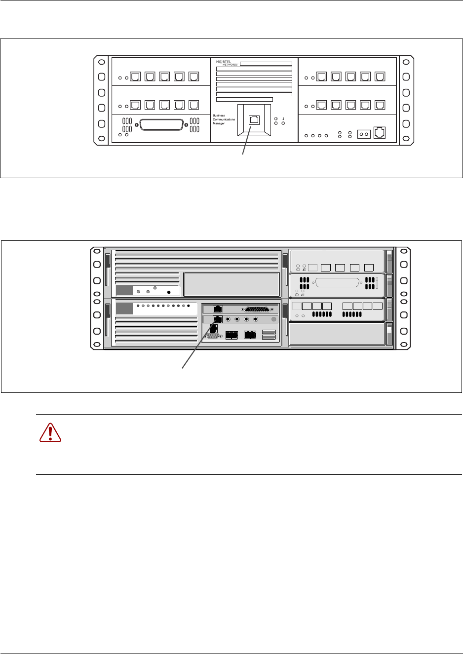
Chapter 3 Install the Business Communications Manager & Expansion Unit Platform Base Chassis 107
Business Communication Manager 3.0 Installation and Maintenance Guide
Figure 59 DS256 connector on the expansion unit
2Plug the other end of the cable into the DS256 connector on the faceplate of the MSC in the
Business Communications Manager platform base chassis. Refer to Figure 60.
Figure 60 Business Communications Manager platform base chassis DS258 connector
Warning: The timing in the Business Communications Manager base unit system is
critical, you must use the correct length cable as supplied with the expansion chassis. The
system may not work properly if you connect the Business Communications Manager
expansion unit using a cable that varies in length.
DS256 connector
DS256 connector
CTM 4
1Aux 2 3 4
DSM 16+
1234 1234
StatusPower

108 Chapter 3 Install the Business Communications Manager & Expansion Unit Platform Base Chassis
P0993133 03
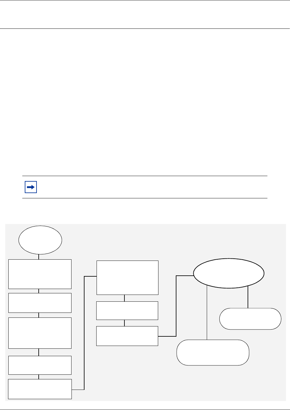
109
Installation and Maintenance Guide
Chapter 4
Install, remove or replace the Media Bay Modules
Use the procedure in this chapter to install, remove or replace the media bay modules in the
Business Communications Manager platform base chassis and the expansion unit.
Install a Media Bay Module
After you set the switches on the media bay modules, you can install them in the Business
Communications Manager or the expansion unit.
The BCM200 platform accommodates a maximum of two media bay modules. The BCM400
platform accomodates a maximum of four media bay modules. If your BCM400 system requires
more than four media bay modules, you need to connect a Business Communications Manager
expansion unit to the Business Communications Manager.
Figure 61 provides an overview of the process for installing media bay modules.
Figure 61 Overview of installing a media bay module
Note: The number of media bay modules you can add varies, depending on the
DS30 resources that are available. Refer to Figure 195 on page 320.
no yes
Set module
DIP
switches
Disconnect cables
from the front of the
server and expansion
unit
Disconnect power from
both units
Remove front bezel
from the expansion
unit to eject blank
filler or MBM
Replace bezel
Restore power to
Business
Communications
Manager and
expansion unit
Reconnect all cables
Use the Unified Manager
to identify the module to
the system
Monitor LEDs for
power and status.
Install new module
Continue with system
initialization
Is this installation
part of a new
system installation?
110 Chapter 4 Install, remove or replace the Media Bay Modules
P0993133 03
Shut down the system
Before you perform any maintenance procedures, read the following warnings to ensure you and
your system are properly protected.
This section describes the recommended procedure for shutting down the Business
Communications Manager prior to installing new media bay modules.
1If you are adding or replacing a module in an active system, follow these steps first:
aAccess the Unified Manager
bChoose System.
cClick the Logoff menu and then click Shutdown.
dClick the Yes button.
eWait until the Status changes to Complete! It is safe to turn off the system.
fClick the Done button.
gExit the Unified Manager.
2Attach one end of the grounding strap to your wrist and the other end to a grounded metal
surface.
3Ensure the cables connected to the front of the Business Communications Manager and the
expansion unit are clearly marked as to how they are connected.
4Remove the cables from all the media bay modules and the MSC on the Business
Communications Manager base function tray and the expansion unit (if attached).
5Disconnect the Business Communications Manager and expansion unit power cords from the
ac outlet.
Warning: If you are installing a new system, or new Business Communications
Manager or expansion unit, refer to Chapter 11, “Install Telephones and Peripherals,”
on page 243 for instructions about installing a new system before you connect the
system to the ac power outlet.
Warning: Failure to follow procedures to properly disconnect the Business
Communications Manager and expansion unit, can result in module or system damage.
Warning: Ensure you are properly grounded before handling modules or any
components that are part of the Business Communications Manager hardware.

Chapter 4 Install, remove or replace the Media Bay Modules 111
Installation and Maintenance Guide
Install a media bay module in the Business Communications
Manager platform base chassis
Use this procedure to install a media bay module in the Business Communications Manager
platform base chassis. Only install the media bay modules when the system is powered down.
1Ensure that the switches on the media bay module are set correctly. For information about how
to set the switches, refer to “Set Media Bay Module Dip Switches” on page 322.
In the case of FEM modules, the switches activate the front ports. Ensure that the switches
accurately reflect the ports you require. Refer to “FEM switch settings” on page 344.
2Select an open media bay.
3With the face of the media bay module facing toward you, insert the media bay module into
the open bay.
4Push the media bay module completely into the unit. You will hear a click when the module is
firmly seated in the media bay.
5Repeat steps 2 to 4 for each media bay module you want to install.
Install a media bay module in the expansion unit
Use this procedure to install a media bay module in the Business Communications Manager
expansion unit chassis. Install the media bay modules when the system is powered down.
1Ensure that the switches on the media bay module are set correctly. For information about how
to set the switches, refer to “Set Media Bay Module Dip Switches” on page 322.
In the case of FEM modules, the switches activate the front ports. Ensure that the switches
accurately reflect the ports you require. Refer to “FEM switch settings” on page 344.
2Select an open media bay.
3With the face of the media bay module facing toward you, insert the media bay module into
the open bay. Ensure that any cables at the rear of the module are clear of the platform base
chassis.
4Push the media bay module into the unit. You will hear a click when the module is firmly
seated in the media bay.
5Repeat steps 2 to 4 for each media bay module you want to install.
6Install the front bezel on the expansion unit
7This procedure is complete.
112 Chapter 4 Install, remove or replace the Media Bay Modules
P0993133 03
Reconnect the equipment
After you install the module correctly into the bay, you must return the equipment to operation in
an orderly manner.
Follow these steps carefully to ensure that you return your system to operation without
endangering the equipment or yourself.
1Plug the power cords for the Business Communications Manager and the expansion unit, if
there is one, back into the ac outlets.
2Connect the cables to the proper outlets on the media bay modules and the MSC on the server.
3Check that the LEDs on the modules are on and indicating the correct state. Refer to “Check
system power and status” on page 129 for a detailed description of the LED states.
4Test existing functions to confirm their operation.
5Configure the module. Refer to the Business Communications Manager Programming
Operations Guide for details.
6This procedure is complete.
Remove a media bay module
Use the procedures is this section to remove one or more media bay modules from a Business
Communications Manager platform base chassis or expansion unit.
Figure 62 provides an overview of the process for removing media bay modules
Note: The Business Communications Manager system starts up when you connect the ac
power cord. System startup takes several minutes to complete.
Caution: DECT modules
Plug the base station RJ45 cables into the DECT module one at a time. Ensure each base
station begins the startup sequence before plugging in the next module.
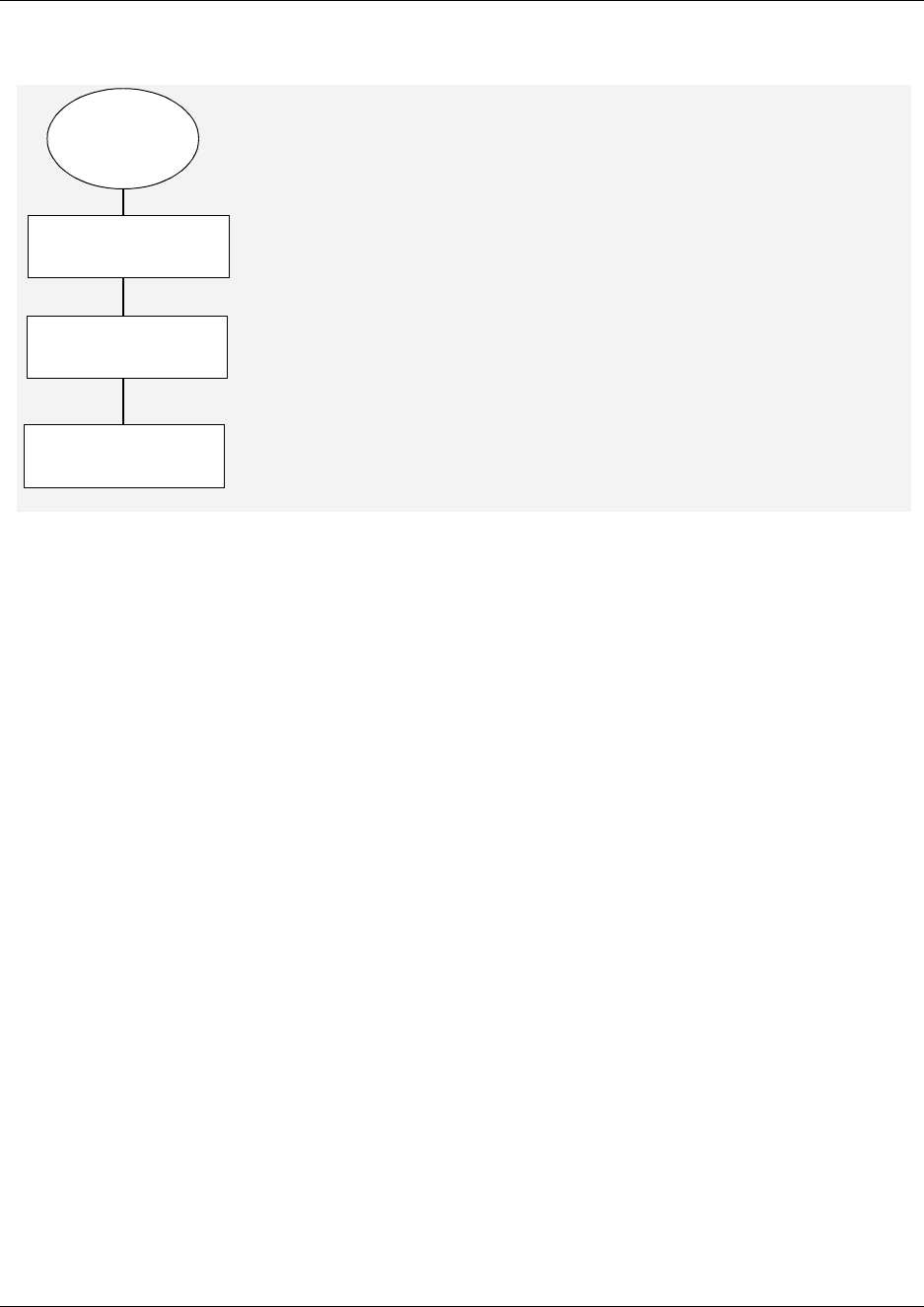
Chapter 4 Install, remove or replace the Media Bay Modules 113
Installation and Maintenance Guide
Figure 62 Overview of removing a media bay module
Remove a media bay module from the Business Communications
Manager platform base chassis
Use this procedure to remove a media bay module from the Business Communications Manager
platform base chassis. Remove the media bay modules after the system is powered down.
1Power down the Business Communications Manager system (see Shut down the system on
page 110).
2Remove any cabling from the media bay module faceplate.
3Grasp the right edge of the MBM ejector lever with your thumb, index and middle fingers.
Pull outward to partially eject the media bay module bay. Pull further on the lever to eject the
media bay module from the bay. Refer to Figure 63 or Figure 64.
4Grasp the top and bottom edges of the media bay module. Remove the media bay module from
the Business Communications Manager platform base chassis MBM bay (see Figure 63,
Figure 64). Place the media bay module in a clean, safe and static free area.
Shutdown
BCM &
expansion
unit
Disconnect power from
both units
Remove module
Remove module
cables
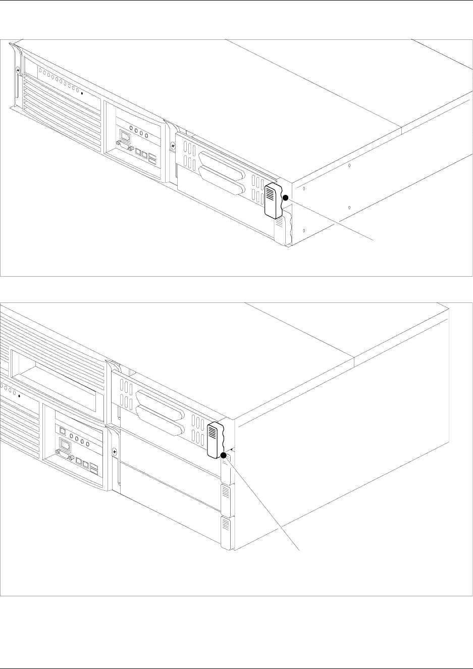
114 Chapter 4 Install, remove or replace the Media Bay Modules
P0993133 03
Figure 63 Remove a BCM200 media bay module
Figure 64 Remove a BCM400 media bay module
5This procedure is complete.
Grasp the edge of the MBM
ejector lever and pull outward
Grasp the edge of the MBM
ejector lever and pull outward
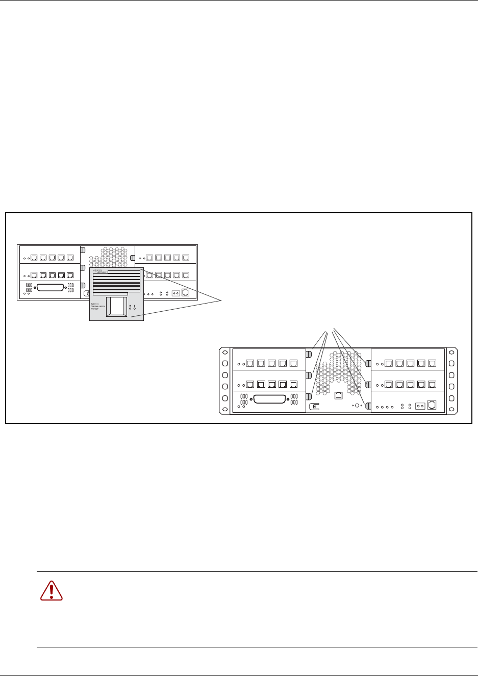
Chapter 4 Install, remove or replace the Media Bay Modules 115
Installation and Maintenance Guide
Remove a media bay module from the expansion unit
Use this procedure to remove a media bay module from the Business Communications Manager
expansion unit. Remove the media bay modules after the system is powered down.
1Remove any cabling from the media bay module faceplate.
2Power down the Business Communications Manager expansion unit system (see Shut down
the system on page 110).
3Remove the expansion unit front bezel.
4Grasp the right edge of the MBM ejector lever. Pull outward to eject the media bay module.
Refer to Figure 65.
Figure 65 Remove the expansion unit front bezel
5Grasp the top and bottom edges of the media bay module. Remove the media bay module from
the Business Communications Manager expansion unit. Place the media bay module in a
clean, safe and static free area.
6This procedure is complete.
Replace a Media Bay Module
When media bay modules require replacement, follow the steps in this section.
Warning: This section describes replacing a module with the same type of module. If you
want to replace a module with a different type of module, you must treat it as a new
installation. Refer to Chapter B, “Telephony Hardware Selection and Settings and review
Figure 200 on page 330 to ensure the new module does not overrun any lines already
assigned to other modules.
Business Communications Manager expansion unit
1. Push against the bottom
2. Pull out from the top
media bay module latches
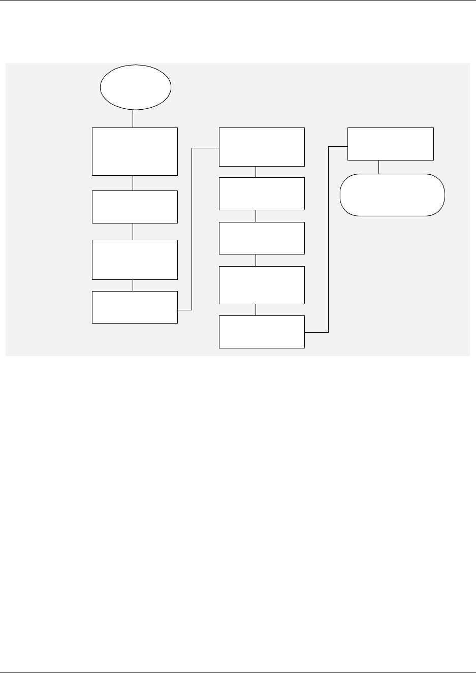
116 Chapter 4 Install, remove or replace the Media Bay Modules
P0993133 03
Figure 66 provides an overview of the process for replacing media bay modules.
Figure 66 Overview of module replacement process
If a media bay module fails, follow this procedure to properly replace the module.
1Follow the steps in “Shut down the system” on page 110 to ensure the system shuts down
correctly.
2Remove all cables and disconnect the Business Communications Manager from the AC power
outlet.
3Remove the front bezel from the unit where the module resides.
4Pull the latch beside the module to be replaced to release the module. Refer to Figure 63 on
page 114.
5Slide the module out of the bay where it is installed.
6Record the switch settings from the old module.
7Set the DIP switches on the new module to match the settings you recorded in the previous
step.
8Refer to “Install a Media Bay Module” on page 109 to install the module into the media bay.
9Refer to “Reconnect the equipment” on page 112 to restore the system to operation.
10 This procedure is complete.
Module
failure
Disconnect cables
from the front of
the server and
expansion unit
Remove power
from both units
Remove front bezel
from expansion unit
Remove failed
module
Set DIP switches
on new module to
match old module
Install new module
in media bay
Replace bezel
Restore power to
BCM and
expansion unit
Reconnect all
cables
Monitor LEDs for
power and status
Check the module
settings in the Unified
Manager
Chapter 4 Install, remove or replace the Media Bay Modules 117
Installation and Maintenance Guide
Wire the Media Bay Modules
This section describes how to wire the cables that connect to the station and trunk modules.
• Station modules require 25-pair wired cables to connect the modules to the equipment in the
telephone room where your telco demarcation point is located. Use a qualified technical
professional to ensure the cable wiring and your interior telephone wiring are correct.
• Trunk modules and DECT base stations are connected using RJ-type jacks. These cables can
be supplied by qualified technical personnel to ensure the correct pin-out.
Figure 67 on page 118 provides an overview of the process for connecting trunk and station wiring
to the Business Communications Manager media bay modules.
Warning: Use only qualified persons to service the system.
The installation and service of this unit must be performed by service personnel with the
appropriate training and experience. Service personnel must be aware of the hazards of
working with telephony equipment and wiring. They must have experience in techniques
that minimize any danger of shock or equipment damage.
Warning: Leakage currents
Service personnel must be alert to the possibility of high leakage currents becoming
available on metal system surfaces during power line fault events on network lines. These
leakage currents normally safely flow to Protective Earth ground via the power cord.
However, if the ac power is unplugged prior to disconnecting the cables from the front of
the base function tray, this hazard can occur.
System shutdown: You must disconnect the media bay module cables from the system
before disconnecting the power cord from a grounded outlet.
System startup: You must reconnect the power cords to an grounded outlet before
reconnecting the cables to the media bay modules.
Danger: Electrical shock hazards
Electrical shock hazards from the telecommunications network and ac mains are possible
with this equipment. To minimize risk to service personnel and users, the Business
Communications Manager system must be connected to an outlet with a third wire ground.
In addition, all unused slots must have blank faceplates installed. The covers on all units
must be in place at the completion of any servicing.
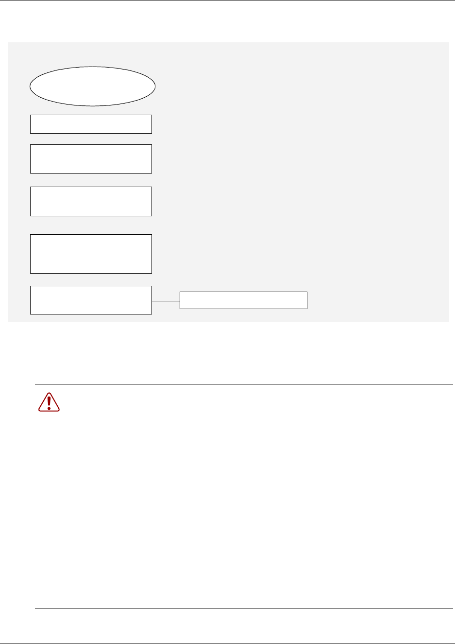
118 Chapter 4 Install, remove or replace the Media Bay Modules
P0993133 03
Figure 67 Trunk and station wiring overview
Module Wiring Warnings
Warning: Electrical shock warning.
The Business Communications Manager media bay modules have been Safety approved
for installation into Business Communications Manager base units and expansion units. It
is the responsibility of the installer and user to ensure that installation of the Business
Communications Manager hardware does not compromise existing Safety approvals.
BEFORE YOU OPEN the Business Communications Manager or Business
Communications Manager expansion unit ensure that the network telecom cables are
unplugged and the unit is then disconnected from the ac power source.
Station modules: The ports on these modules are meant to be connected only to approved
digital telephones and peripherals with the proper cables on a protected internal wiring
system.
Do not connect any telephones to wiring that runs outside of the building.
Read and follow the installation instructions carefully.
Media bay modules installed.
Read warnings
Wire cables to telco
demarcation block
Connect cables to
appropriate trunk modules.
Wire internal 25-pair cables
to station set distribution BIX
block for your building
Connect amphenol cable to
appropriate station modules Continue with setup procedures
Trunk and station modules
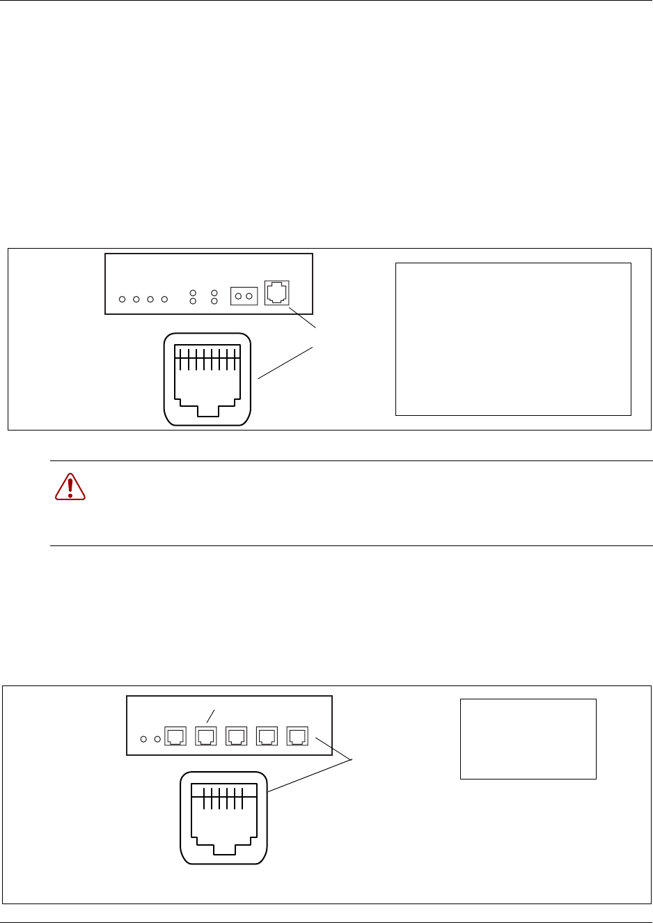
Chapter 4 Install, remove or replace the Media Bay Modules 119
Installation and Maintenance Guide
Connect the Media Bay Modules to Service Providers
To connect DTM, CTM, CTM8, 4X16 CTM, or BRIM S/T media bay modules to the network,
follow these steps:
1On the front of the module, locate the RJ48C jack (DTM), RJ45 jack (BRI), or the
RJ11 jacks (CTM and 4X16 modules).
2Wire one end of the cable to the telco demarcation blocks of the building.
•Figure 68 shows the wiring pin outs for a DTM to connect to a service provider.
Figure 68 DTM RJ48C wiring array
•Figure 69 shows the wiring pin-out for a CTM, a CTM8, or the CTM jacks on a 4X16
module, to connect to the service provider.
All the modules have an auxiliary jack (the CTM8 has two). Do not attempt to plug digital
equipment into this jack.
Figure 69 CTM RJ11 wiring array
Warning: If you are using a service provider channel service unit (CSU), you must
disable the Business Communications Manager system internal CSU using Business
Communications Manager Unified Manager. For more information, refer to the Business
Communications Manager 3.0, Programming Operations Guide.
1 2 3 4 5 6 7 8
DTM connector To network To plug
Receive from
network 1- Rring
2 - Rtip
3 - Rshield
Transmit to network 4-Tring
5-Ttip
6-Tshield
RJ48C jack
6 5 4 3 2 1
CTM
connector
RJ11 jacks
Auxiliary jack Pin #/connection
3- Ring
4 - Tip
The CTM 8 has ten RJ11 jacks, including two
auxiliary jacks.
The 4X16 and CTM media bay modules have
four RJ11 jacks.
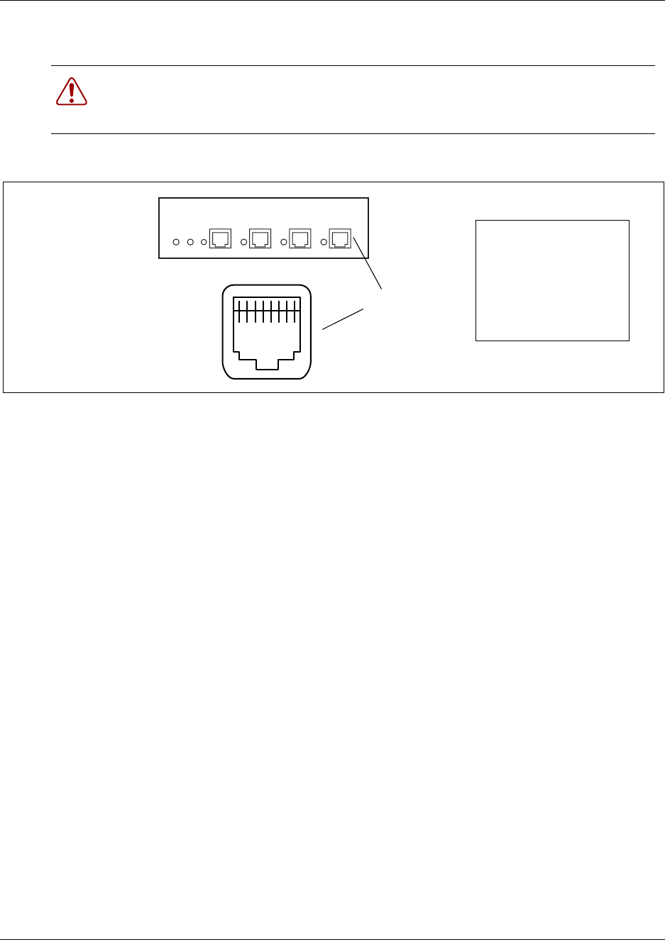
120 Chapter 4 Install, remove or replace the Media Bay Modules
P0993133 03
•Figure 70 shows the wiring pin-out for an BRIM S/T to the service provider.
Figure 70 BRIM S/T RJ45 wiring array
3Insert the connector into the jack on the module.
Refer to the Business Communications Manager 3.0 Programming Operations Guide for steps
about changing the default settings for each line/loop.
4You can now use the Unified Manager to configure the lines or sets associated with the
module. Refer to the Business Communications Manager 3.0 Programming Operations Guide.
Warning: The BRIM S/T must only be connected to an NT1 provided by the service
provider. The NT1 must provide a Telecommunication Network Voltage (TNV) to Safety
Extra Low Voltage (SELV) barrier.
8 7 6 5 4 3 2 1
BRIM S/T connector
RJ45 jacks
Pin #/connection
3- TX-
4 - RX-
4-RX-
5-RX+
Chapter 4 Install, remove or replace the Media Bay Modules 121
Installation and Maintenance Guide
Wire Media Bay Modules to Internal Connections
After you have the trunk modules wired, you can install the wiring to the station modules. These
are the modules which connect to the internal telephone sets.
All station module wiring uses 25-pair cable with a female amphenol connector at the module end.
Follow these steps to connect the wiring for the DSM 16, DSM 32, ASM 8, or 4X16 modules:
1Wire 16 wire pairs from the amphenol connector to the local connecting blocks (BIX) so they
connect to the 16 station sets you want connected to this module.
Use Table 13 and Figure 71 on page 122.
For an overview of BIX wiring conventions, refer to the Business Communications Manager
3.0 BIX Box Wiring Guide.
Note: DSM 32 modules require two 25-pair cables.
Note: Use 16 wire pairs from each connector for the DSM 32.
Note: If you are connecting an DSM 16, 4X16, or DSM 32, use Table 13 on page 122.
If you are connecting an ASM 8, use the Table 14 on page 123.
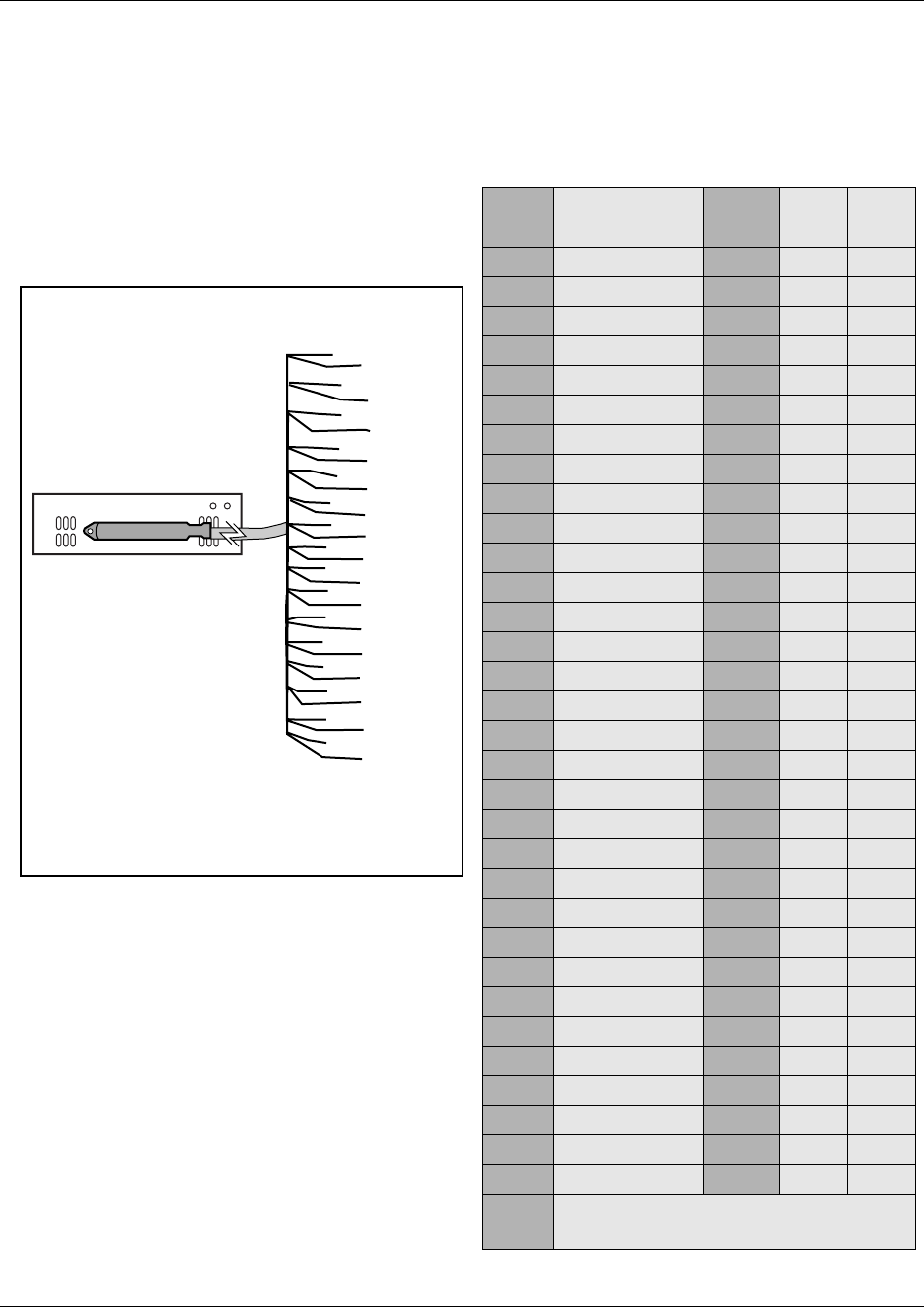
122 Chapter 4 Install, remove or replace the Media Bay Modules
P0993133 03
Table 13 and Figure 71 provide the wiring scheme for the DSM 16, 4X16 and DSM 32 modules.
The Sets heading indicates the position of the set on the BIX block. Set DNs are allocated by the
Business Communications Manager based on the DS30 channel setting on the station module.
Table 13 DSM wiring chart
Pin Wire color Port Sets
1st Sets
2nd
Figure 71 Wiring for DSM 16, 4X16, and DSM 32 26 White-Blue X01 117
1Blue-White X01 117
27 White-Orange X02 218
2Orange-White X02 218
28 White-Green X03 319
3Green-White X03 319
29 White-Brown X04 420
4Brown-White X04 420
30 White-Slate X05 521
5Slate-White X05 521
31 Red-Blue X06 622
6Blue-Red X06 622
32 Red-Orange X07 723
7Orange-Red X07 723
33 Red-Green X08 824
8Green-Red X08 824
34 Red-Brown X09 925
9Brown-Red X09 925
35 Red-Slate X10 10 26
10 Slate-Red X10 10 26
36 Black-Blue X11 11 27
11 Blue-Black X11 11 27
37 Black-Orange X12 12 28
12 Orange-Black X12 12 28
38 Black-Green X13 13 29
13 Green-Black X13 13 29
39 Black-Brown X14 14 30
14 Brown-Black X14 14 30
40 Black-Slate X15 15 31
15 Slate-Black X15 15 31
41 Yellow-Blue X16 16 32
16 Blue-Yellow X16 16 32
42-40
17-25
no connections
T=Tip
R=Ring
8R
7R
6R
5R
4R
3R
2R
1 R
9R
10R
11R
12R
13R
14R
15R
16R
33T
32T
31T
30T
29T
28T
27T
26 T
34T
35T
36T
37T
38T
39T
40T
41T
DSM 16, 4X16
25-pair connector
DSM 32
The second 25-pair connector is
wired in the same sequence as the
first one
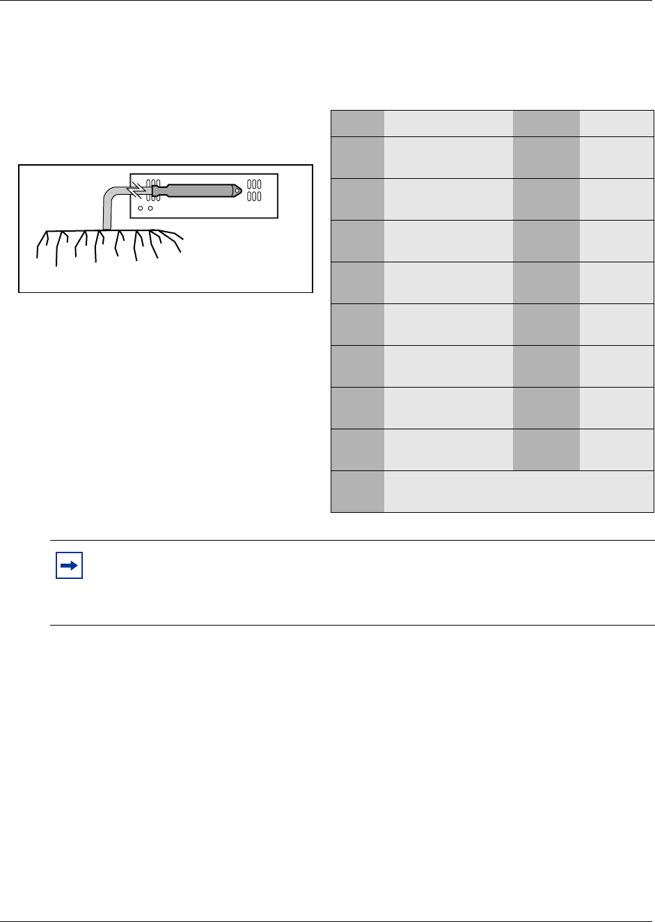
Chapter 4 Install, remove or replace the Media Bay Modules 123
Installation and Maintenance Guide
Table 14 and Figure 72 provide the wiring scheme for the eight pairs that connect to the ASM.
2Install the telephones and peripheral equipment (if a new system):
aAttach the cables for the telephones to the connecting blocks (BIX).
bInstall the telephones. Refer to Chapter 14, “Install Optional Telephony Equipment,” on
page 287.
3Plug the female amphenol connector into the interface on the front of the module.
4Set up any mobile system you are using.
• Ensure the base stations are correctly installed and connected to the appropriate modules
on the Business Communications Manager. In the case of the NetVision wireless system,
ensure that the access point is correctly set up to connect to the Business Communications
Manager LAN or WAN.
Table 14 ASM wiring chart
Pin Wire color Port Set
Figure 72 Wiring for an ASM 8 26 White-Blue X01 1
1Blue-White X01 1
27 White-Orange X02 2
2Orange-White X02 2
28 White-Green X03 3
3Green-White X03 3
29 White-Brown X04 4
4Brown-White X04 4
30 White-Slate X05 5
5Slate-White X05 5
31 Red-Blue X06 6
6Blue-Red X06 6
32 Red-Orange X07 7
7Orange-Red X07 7
33 Red-Green X08 8
8Green-Red X08 8
34-50 no connection
9-25
Note: Refer to “Line and extension numbers for specific modules” on page 332 to see the
relationship between the DS30 channel number and the DNs. Configuration information is
included in the chapters on setting up modules and DNs in the Business Communications
Manager 3.0 Programming Operations Guide.
8R
3
3T32T
7R
31T
6R
30T
5R29T
4R
28T
3R 27T
2R 26T
1R 25-pair female
amphenol
connector
124 Chapter 4 Install, remove or replace the Media Bay Modules
P0993133 03
• Configure and register the handsets according to the instructions provided for each type of
system.
— Companion: Programming Operations Guide
—DECT: DECT Installation and Maintenance Guide
— T7406: T7406 Cordless Handset Installation Guide
— NetVision and NetVision data: IP Telephony Configuration Guide
5This procedure is complete.
FEM Wiring
A Fiber Expansion module (FEM) allows you to upgrade from a Norstar system to a Business
Communications Manager system by reusing the Norstar expansion modules. The expansion
modules connect to the FEM module using the same fiber cable that connected them to the Norstar
fiber expansion card.
Warning: Handling optical fiber cables:
If the cable is too long, ensure that it is coiled correctly using the fiber spool.
Coil excess fiber cable carefully around the spool provided. Do not bend the cable around
any tight corners. Bends in the fiber cable must not be less than 100 mm in diameter. Place
the fiber cable spool into a slot at the back of the cable trough in the Norstar module.
Note: If you enable all six jacks of the FEM module, the FEM module is the only module
you can install on your Business Communications Manager system, because each port
requires one DS30 channel. Refer to “FEM switch settings” on page 344.
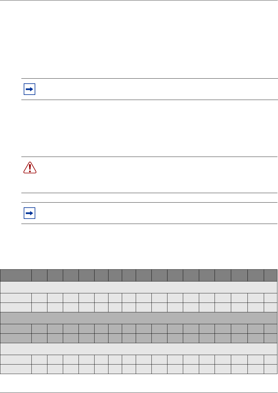
Chapter 4 Install, remove or replace the Media Bay Modules 125
Installation and Maintenance Guide
Connect the fiber cables
Follow these steps to connect your Norstar expansion modules to a FEM module installed into a
Business Communications Manager.
1Ensure the Business Communications Manager is powered-up and functional.
2Connect the fiber cables from the Norstar expansion modules to the jacks on the FEM module.
aConnect the Norstar Line Modules to the FEM beginning at fiber port 1.
bConnect Norstar Extension Modules to the FEM beginning at fiber port 6.
3Change the DN records in the Unified Manager or change the set wiring, as required, to match
your system.
Table 15 compares the designated extension numbers on the Norstar and on the Business
Communications Manager.
Note: The DIP switch settings you chose determines which FEM ports are available.
There are only six ports available. Refer to “FEM switch settings” on page 344.
Warning: When you connect a Norstar station module to an FEM, the extension numbers
of the telephones connected to the station module may change. To keep the same
extension numbers, you will have to change the DNs of the telephones or change the
telephone wiring to correspond with the required DNs.
Note: If you connect a Norstar station module amphenol cable directly to a DSM, you do
not have to modify the wiring connections. Ensure you select the correct DS30 number.
Table 15 Extension comparison chart
Ports 1 2 3 4 5 6 7 8 9 10 11 12 13 14 15 16
DS30 channel 2, FEM port 1
Norstar 221 222 223 224 225 226 227 228 229 230 231 232 233 234 235 236
BCM 225 226 227 228 221 222 223 224 233 234 235 236 229 230 231 232
DS30 channel 3, FEM port 2
Norstar 237 238 239 240 241 242 243 244 245 246 247 248 249 250 251 252
BCM 241 242 243 244 237 238 239 240 249 250 251 252 245 246 247 248
DS30 channel 4, FEM port 3
Norstar 253 254 255 256 257 258 259 260 261 262 263 264 265 266 267 268
BCM 257 258 259 260 253 254 255 256 265 266 267 268 261 262 263 264

126 Chapter 4 Install, remove or replace the Media Bay Modules
P0993133 03
Installation/Replacement Troubleshooting
The Business Communications Manager media bay modules are working when both the Power
and Status LEDs on the modules are on, and are not blinking.
• If the Power LED does not light, refer to “Shut down the system” on page 110. After the
Business Communications Manager is correctly shut down, remove the module and check the
connectors at the back of the module for dirt or loose connections.
After you reinstall the module, if the LED still does not light, install a different module into
that bay to check for a possible fault in the backplane. If the second module works, assume
that the first module is defective and replace it with a new module.
• If the Power LED lights, but the Status light does not light, or continues to blink, wait 10
minutes to allow for information download. If the light continues to blink, power down the
system and check the DIP switch settings on the module. Ensure the connector is clean and
free from debris.
• If the LEDs are on solid, but the module cannot communicate or be communicated with, check
the Unified Manager settings for the module.
For information about the LEDs on the Business Communications Manager and expansion unit,
refer to See Table 16 on page 129.
DS30 channel 5, FEM port 4
Norstar 269 270 271 272 273 274 275 276 277 278 279 280 281 282 283 284
BCM 273 274 275 276 269 270 271 272 281 282 283 284 277 278 279 280
DS30 channel 6, FEM port 5
Norstar 285 286 287 288 289 290 291 292 293 294 295 296 297 298 299 300
BCM 289 290 291 292 285 286 287 288 297 298 299 300 293 294 295 296
DS30 channel 7, FEM port 6
Norstar 301 302 303 304 305 306 307 308 309 310 311 312 313 314 315 316
BCM 305 306 307 308 301 302 303 304 313 314 315 316 309 310 311 312
Table 15 Extension comparison chart
Ports 1 2 3 4 5 6 7 8 9 10 11 12 13 14 15 16
127
Installation and Maintenance Guide
Chapter 5
Business Communications Manager System Startup
This chapter describes initial system startup procedures for the Business Communications
Manager.
The Business Communications Manager and expansion unit are each powered through an AC
outlet. The voltage required depends on the geographical location of the units.
All systems are initially set at the factory, based on the intended destination. You must check that
the voltage and wiring are correct for you system before you connect any of the units to the power
source. Incorrect power settings result in equipment damage
Read the following warnings. You must protect yourself and the Business Communications
Manager units from possible electrical shocks.
Warning: Use only qualified persons to service the system
The installation and service of this unit must be performed by service personnel with the
appropriate training and experience. Service personnel must be aware of the hazards of
working with telephony equipment and wiring. They must have experience in techniques
that minimize any danger of shock or equipment damage.
Danger: Electrical shock hazards
Electrical shock hazards from the telecommunications network and ac mains are possible
with this equipment. To minimize risk to service personnel and users, the Business
Communications Manager system must be connected to an outlet with a third wire ground.
In addition, all unused slots must have blank faceplates installed. The covers on all units
must be in place at the completion of any servicing.
Warning: Leakage currents
Service personnel must be alert to the possibility of high leakage currents becoming
available on metal system surfaces during power line fault events near network lines. These
leakage currents normally safely flow to Protective Earth ground via the power cord.
System shutdown: You must disconnect the media bay module cables from the system
before disconnecting the power cord from a grounded outlet.
System startup: You must reconnect the power cords to a grounded outlet before
reconnecting the cables to the media bay modules.
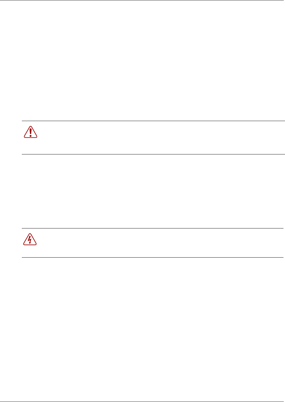
128 Chapter 5 Business Communications Manager System Startup
P0993133 03
Check Power and Wiring
The Business Communications Manager system is available as North American and International
versions. Ensure that the power supply is correct for your location.
• 2.0 hardware has a standard power supply which requires manual adjustment for the voltage
by setting a switch located on the face of the power supply.
• 2.5 and 3.0 systems have standard power supplies and redundant power supplies which adjust
automatically to the required voltage.
Follow this procedure to check the voltage and wiring, and power up the system:
1Check all wiring before connecting power to the Business Communications Manager units.
2Connect the Business Communications Manager power cord to an electrical outlet that is a
non-switchable, third wire ground ac outlet.
If you use a power bar, plug the power cords into the power bar and connect the power bar to
the ac outlet.
3Connect the Business Communications Manager expansion unit power cord to an electrical
outlet that is a non-switchable, third wire ground ac outlet.
4This procedure is complete.
Warning: Connecting power
Always connect power to the Business Communications Manager platform system and
expansion units before you reconnect the cabling to the front of the units.
Danger: Do not fasten power supply cords.
Do not fasten the Business Communications Manager or Business Communications
Manager expansion unit power supply cords to any building surface.
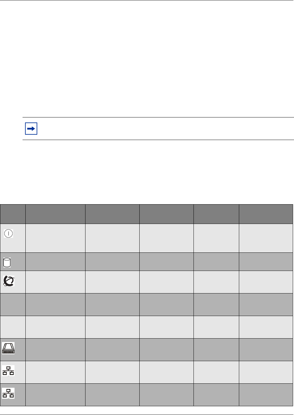
Chapter 5 Business Communications Manager System Startup 129
Installation and Maintenance Guide
Check system power and status
After you connect power to the Business Communications Manager system, the Power LED on the
front of the base function tray and expansion unit lights. Once the system services have
reactivated, the Status LED turns solid green.
The Power LED can indicate RED if the system is in standby mode whereby power is
available, but shutdown by the operating system (when UPS) or Overtemp.
LEDs in position 3-8 will flash when the SSM is not communicating (during startup,
shutdown or operating system hang).
Table 16 describes the possible operating states of the LEDs on the front of the Business
Communications Manager base function tray. The Business Communications Manager expansion
unit has both a power and a status LED, which provide the same indicators as for the base function
tray.
Note: During system initialization, the system performs diagnostics on the hardware
configuration size and installation. If the power fails, system data remains in memory.
Table 16 Business Communications Manager LED states
LED
Label Description Green LED On Green LED Flash Red LED On
(Only) Green LED Off
Indicates state of all
powered components. OK N/A voltage
irregularity or
component
failure
N/A
Indicates access to
the system disk drive indicates disk drive
activity N/A N/A N/A
Indicates condition of
system status all monitored
services are
functioning
Failure in one or
more telephony
service
N/A not all services are
working
1PCI Device/
WAN Port #1 Device is present
and the driver is
active
driver is not running N/A Device is not
present.
2PCI Device/
WAN Port #2 Device is present
and the driver is
active
driver is not running N/A Device is not
present.
Modem Device is present
and the driver is
active
driver is not running N/A Device is not
present.
LAN 1 Device is present
and the driver is
active
driver is not running N/A Device is not
present.
LAN 2 Device is present
and the driver is
active
driver is not running N/A Device is not
present.
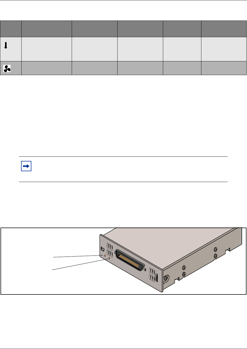
130 Chapter 5 Business Communications Manager System Startup
P0993133 03
1If the base function tray Power LED does not light:
aDisconnect the power cords.
bCheck all cables and power connections. Ensure that the ac outlet has power.
cReconnect the power cords.
2If the Power LED is red and there is no power, use a paper-clip to select the reset button.
Alternatively power cycle the system to restart.
3You are now ready to connect the system to the network and initialize it.
When the system power is on, and the system has successfully booted, the power and status LEDs
on the faceplates of the media bay modules are lit and remain constant. Figure 73 shows an
example of a media bay module and the LEDs on the module faceplate.
Figure 73 Module power and status LEDs
Temperature Temperature is
below threshold. N/A Sensor is
non-operational
or Temperature
is out of range.
N/A
Fans All installed fans are
working N/A Fan failure. N/A
Note: You can monitor the state of the Business Communications Manager LEDs
from your computer. Refer to “Access the System Status Monitor to Monitor
LEDs” on page 292.
Table 16 Business Communications Manager LED states (Continued)
LED
Label Description Green LED On Green LED Flash Red LED On
(Only) Green LED Off
All modules have a
power
and
status
LEDs DSM16
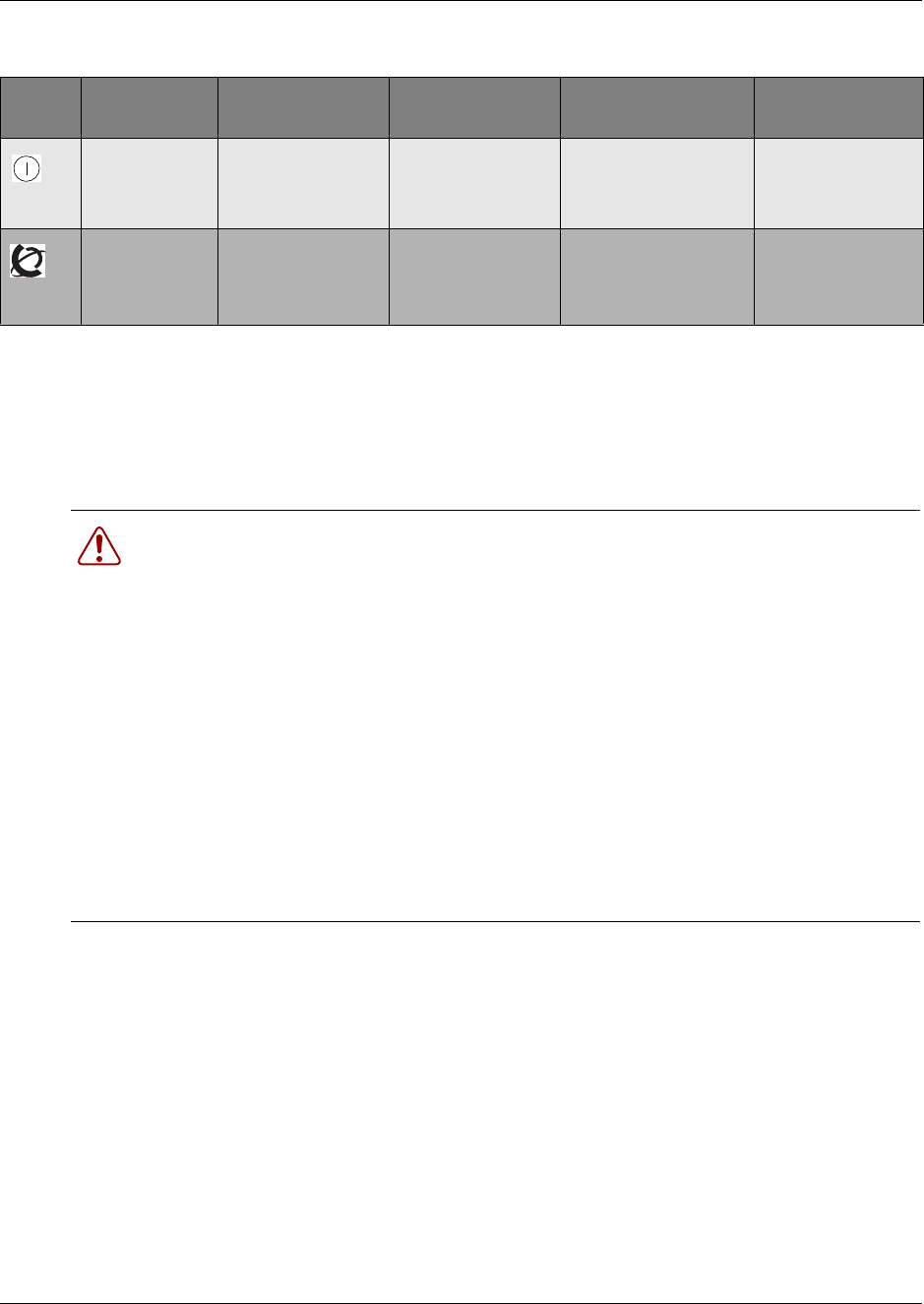
Chapter 5 Business Communications Manager System Startup 131
Installation and Maintenance Guide
Connect the Data Networking Hardware
This section describes how to connect network cards to the Business Communications Manager
system.
Table 17 Module power and status LED states
LED
Label Description Green LED On Green LED Flash Red LED On (Only) Green LED Off
Indicates state
of system
power.
OK Check for hardware
problem with fan,
power or heat inside
housing
a minimum of 1 PS
needs attention no power to the
module
Indicates
condition of
system status
all monitored
services are
functioning
in startup/shutdown
mode
check for problem
with MSC wiring
N/A not all services are
working, MSC may
not have started
correctly
Warning: Check with your network administrator before you connect the Business
Communications Manager to the network to ensure there are no IP address conflicts.
The default address for the Business Communications Manager system:
• IP: 10.10.10.1
• Subnet: 255.255.255.0
Warning: If the default IP address would create a network conflict, you must change the
IP address of the Business Communications Manager before you connect any network
connections.
To change the IP address outside of a network, you can use one of the following:
• a terminal and a null modem cable
• a computer and an ethernet crossover cable
Refer to “Use of a null modem serial cable” on page 137 or “Ethernet crossover cable
usage” on page 140 for detailed instructions about connecting to the Business
Communications Manager.
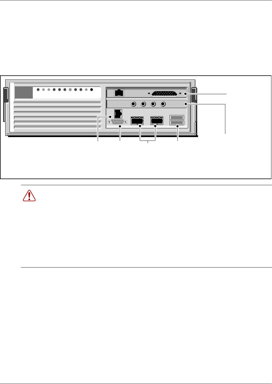
132 Chapter 5 Business Communications Manager System Startup
P0993133 03
Connect the cards
The data networking hardware (MSC) is installed in the Business Communications Manager at the
factory. All systems have dual embedded ethernet interfaces. Some models come with an
embedded V.90 modem. WAN cards and modems are ordered separately. Figure 74 shows a
BCM200 configuration with a field-installed WAN card.
Figure 74 Base function tray data cards
Warning: Do not plug the WAN or modem cables into the system unless it is running.
For maintenance shutdowns, ALWAYS follow this process:
aShut down the software through the Unified Manager, if possible.
bRemove all cable connects from the front of the base function tray and expansion
unit.
cRemove power from the Business Communications Manager and the expansion
unit.
dDO NOT RECONNECT the cables to the front of the units until the power
connection has been restored.
Note: Your system may not have all the cards indicated.
Modem port (North
America only)
Media services card
(BCM200 version)
USB
ports
Etherne
t ports
COM
port
WAN card (fiel
d
upgrade) North
America
version shown
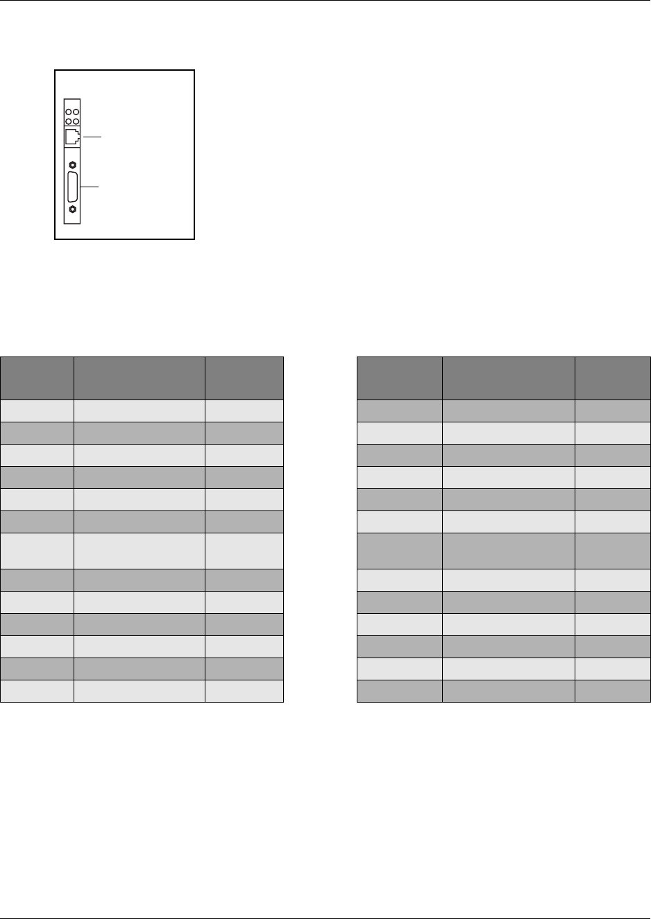
Chapter 5 Business Communications Manager System Startup 133
Installation and Maintenance Guide
Connect wiring to the WAN card
Table 18 shows the wire connections for a DB25 adapter cable.
Ensure the system is powered up before connecting this cable.
To connect the WAN card using the RJ48C connector, insert the wide
area network (WAN) cable into the RJ48C jack on the WAN card.
For information about the location of the WAN card, refer to Figure 74
on page 132.
To connect the WAN card using the DB26 connector, use an adapter
cable to connect the wide area network (WAN) cable to the DB26
connector on the WAN card. These adapter cables are available from
your Business Communications Manager supplier.
Note: Not all systems are equipped with a WAN card.
Table 18 DB25 adapter cable
DB26 on
WAN card Signal DB25 cable DB26 on
WAN card Signal DB25 cable
1Chassis Ground 114 14
2Transmit Data 215 Transmit Clock 15
3Receive Data 316 16
4Request to Send 417 Receive Clock 17
5Clear to Send 518 18
6Data Set Ready 619 19
7Signal Ground/
Common Return 720 Data Terminal Ready 20
8Data Carrier Detect 821 21
9 9 22 22
10 10 23 23
11 11 24 External Clock 24
12 12 25 25
13 13 26
RJ48c jack
WAN card face
DB26 connec-
tor (female)

134 Chapter 5 Business Communications Manager System Startup
P0993133 03
Connect wiring to the modem
Table 19 shows the wire connections for a RS-422/EIA 530 cable
Ensure the system is powered up before connecting this cable.
To connect the modem, insert a PSTN line into the Line jack on the
base function tray modem interface. For information about the
location of the modem interface, refer to Figure 74 on page 132.
Note: Not all systems are equipped with a modem.
Table 19 RS-422/EIA 530 adapter cable
DB26 on
WAN card Signal RS-422/EIA
530 cable DB26 on
WAN card Signal RS-422/EIA
530 cable
1Protective Ground 114 Transmit Data B 14
2Transmit Data A 215 Transmit Clock A 15
3Receive Data A 316 Receive Data B 16
4Request to Send A 417 Receive Clock A 17
5Clear to Send A 518 18
6Data Set Ready A 619 Request To Send B 19
7Signal Ground 720 Data Terminal Ready A 20
8Data Carrier Detect A 821 21
9Receive Clock B 922 Data Set Ready B 22
10 Data Carrier Detect B 10 23 Data Terminal Ready B 23
11 External Clock B 11 24 External Clock A 24
12 Transmit Clock B 12 25 25
13 Clear To Send B 13 26

Chapter 5 Business Communications Manager System Startup 135
Installation and Maintenance Guide
Table 20 shows the wire connections for a V.35 adapter cable.
Table 21 shows the wire connections for a DB15 X.21 adapter cable.
Table 20 V.35 Adapter Cable
DB26 on
WAN card Signal V.35 cable DB26 on
WAN card Signal V.35 cable
1Protective Ground A14 Transmit Data B S
2Transmit Data A P15 Transmit Clock A Y
3Receive Data A R16 Receive Data B T
4Request to Send C17 Receive Clock A V
5Clear to Send D18
6Data Set Ready E19
7Signal Ground B20 Data Terminal Ready H
8Data Carrier Detect F21
9Receive Clock B X22
10 23
11 External Clock B W24 External Clock A U
12 Transmit Clock B AA 25
13 26
Table 21 DB15 X.21 adapter cable
DB26 on
WAN card Signal DB15
X.21 cable DB26 on
WAN card Signal DB15
X.21 cable
1Chassis Ground 114 Transmit Data B 9
2Transmit Data A 215
3Receive Data A 416 Receive Data B 11
4Request to Send A 317 Receive Clock A 6
5Clear to Send A 518
619 Request To Send B 10
7Signal Ground 820
821
9Receive Clock B 13 22
10 23
11 External Clock B 14 24 External Clock A 7
12 25
13 Clear To Send B 12 26

136 Chapter 5 Business Communications Manager System Startup
P0993133 03
Install the cards
Refer to Chapter 10, “Replace Data Cards and Processing Hardware,” on page 217 for the removal
and installation process for these cards.
Initialize the System
After starting the Business Communications Manager system, you are ready to set the initial
configuration parameters.
The initial configuration defines your Business Communications Manager to the network. It also
gives the system a unique identity and initial parameters. From that point, you can continue with
the specific configurations for your system, which are described in Business Communications
Manager 3.0 Programming Operations Guide, and the other user guides for each optional
application you choose to add to your system.
Data parameter requirements
Obtain the following parameter values from an Internet Service Provider (ISP) or corporate
network administrator.
• initial IP address and netmask for each network interface
• primary (and optional secondary) DNS servers
• default next-hop router
• fractional T1 channel numbers (if you are using fractional TI)
• system name
• WAN link protocol
• frame relay DLCI / CIR (if applicable)
• V.90 modem settings (North America only)
Default IP settings
All Business Communications Manager systems are shipped with this default address:
• IP: 10.10.10.1
• Subnet: 255.255.255.0
Warning: Before using this address on your network, check with your system
administrator. If this address conflicts with the LAN settings, you can cause network
damage if you connect the network without changing the IP address.

Chapter 5 Business Communications Manager System Startup 137
Installation and Maintenance Guide
If you can use the default IP address, you can connect the Business Communications Manager
server to the LAN. This allows you to configure to the Business Communications Manager system
from your PC through the Unified Manager.
Connecting when there is an IP address conflict
If you cannot use the default IP address, you must change the IP address of the Business
Communications Manager system through one of these connections:
• a terminal and a null modem cable. Refer to “Use of a null modem serial cable” on page 137.
• a computer and an Ethernet crossover cable. Refer to “Ethernet crossover cable usage” on
page 140.
After you set the initial parameters, you can connect to the Unified Manager through the network
to complete the system setup using the Quick Start Wizard.
If you do not have a network connection, you can also access a Quick Start Wizard through a serial
link.
For detailed information about configuring the Business Communications Manager system, refer
to the Business Communications Manager 3.0, Programming Operations Guide
Use of a null modem serial cable
You must use a null modem cable connection to the Business Communications Manager base
function tray if the default IP address is not compatible with your LAN or WAN network.
Required equipment:
• null modem cable
• VT100-compatible terminal or a computer that has a terminal program such as Hyperterminal
Warning: Your terminal must be VT100-compatible and must support the VT100
National Character set. If the terminal does not support the National Character set, the text
displays incorrectly.
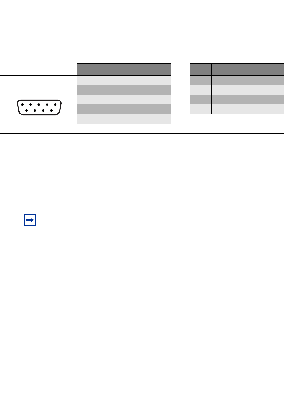
138 Chapter 5 Business Communications Manager System Startup
P0993133 03
Null modem cable setup
Table 22 shows the correct wiring for the Business Communications Manager serial port of the
null modem cable.
Transmission parameters:
• 9600 bits per second
• 8 data bits
• no parity
•1 stop bit
• hardware flow control
Table 22 Serial port pinout
Figure 75 Serial pinout Pin Signal Pin Signal
1Data Carrier Detect (DCD) 6Data Set Ready (DSR)
2* Serial data in (RX) 7Request to Send (RTS)
3* Serial data out (TX) 8Clear to Send (CTS)
4Data Terminal Ready (DTR) 9Ring Indicator (RI)
5* Ground
* required connections
Note: For instructions about how to set the transmission parameters, refer to the terminal
or terminal emulation program documentation. The Business Communications Manager
system supports carriage return.
12345
6789
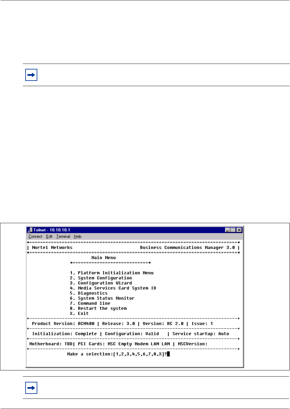
Chapter 5 Business Communications Manager System Startup 139
Installation and Maintenance Guide
Display the configuration menus
To perform this procedure, the Business Communications Manager must be correctly powered up,
as described in “Check system power and status” on page 129.
1Attach the null modem cable to the serial port on the Business Communications Manager.
2Attach the other end of the null modem cable to the serial port on the terminal or computer.
3Ensure that the Business Communications Manager and your terminal or computer are turned
on.
4If you are using a computer, start your VT100 terminal program.
5Press <ENTER>.
6When prompted for a User ID, type:
ee_admin <ENTER>.
7When prompted for a Domain, press <ENTER>.
8When prompted for a Password, type: eedge <ENTER>
The Main Menu screen appears. Refer to Figure 76.
Figure 76 Main Menu
Note: The location of the transmit (TX) and receive (RX) pins on your terminal can vary.
Refer to your terminal or computer documentation to confirm pin locations.
Note: If the Initialization Menu screen appears instead of the Main Menu shown above,
your Business Communications Manager system is not initialized correctly.

140 Chapter 5 Business Communications Manager System Startup
P0993133 03
9If you want to change the IP addressing, enter 2 (System Configuration) and follow the
prompts.
10 If you want to configure the system through the serial port, enter 3 (Configuration Wizard).
This wizard also allows you to change the IP addressing information.
This Wizard has the same information as the Quick Start Wizard that you access through the
Unified Manager, but in a slightly different format. Refer to the Business Communications
Manager 3.0 Programming Operations Guide for a detailed description of the fields that occur
in the Configuration Wizard.
Ethernet crossover cable usage
You use an ethernet crossover cable connected to a computer with a network card to connect your
computer to the LAN card in the Business Communications Manager. With this connection, you
can run Business Communications Manager Unified Manager to configure the Business
Communications Manager system when you are unable to immediately connect your system to the
live LAN card or your system does not have a network connection.
You use this type of connection in these situations:
• the computer you are using does not have access to the Business Communications Manager
system through the network
• the Business Communications Manager is not connected to a LAN or WAN
• you have to change the IP address and netmask for the Business Communications Manager
system before you connect it to the network
Set the crossover connections
To connect to the Business Communications Manager using an Ethernet crossover cable, you need
a computer equipped with a 10/100 Base T network interface card and TCP/IP protocol. Figure 77
shows the connections required.
Note: When you change IP address, Region, Template and/or Start DN, the system
prompts you for a restart after you accept the changes.
After the system restarts, you can continue with your system configuration.
Warning: Changing this information on an existing system completely erases the
telephony programming and disables the telephony system. It also reboots the Business
Communications Manager and expansion unit.
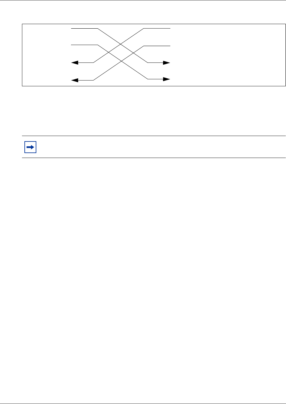
Chapter 5 Business Communications Manager System Startup 141
Installation and Maintenance Guide
Figure 77 Ethernet crossover cable
Configure your computer
You must configure your computer before you use it to connect to the Business Communications
Manager system.
1Click Start, Settings, Control Panel.
2Double click the Network icon.
3Select your TCP/IP adapter, and then click the Properties button.
4Click the IP Address tab.
5Click the Specify an IP address option.
6In the IP Address field, enter 10.10.10.2.
7In the Subnet Mask field, enter 255.255.255.0.
8Click OK.
9Click OK.
10 Click Yes to restart the PC.
Connect the Ethernet crossover cable
After you configure the computer, connect the computer to the Business Communications
Manager base function tray in the following manner:
1Shut down the computer.
2Attach one end of the Ethernet crossover cable to the LAN card on the Business
Communications Manager.
3Connect the other end of the cable to the network interface card on your computer.
4Start the computer.
5Log on to the Unified Manager using the default IP address.
Note: Your interface can differ, depending on what version of system software you are
using. The task in this section is to specify IP and subnet addresses for the computer.
3TD+
6TD-
1RD+
2RD-
3TD+
6TD-
1RD+
2RD-

142 Chapter 5 Business Communications Manager System Startup
P0993133 03
6Use the Quick Start Wizard to create the system configuration.
Refer to the Business Communications Manager 3.0 Programming Operations Guide for
details about using the wizard. The Programming Operations Guide provides a detailed record
about the information that you require to configure basic system programming.
Enter the software keycodes
If you have purchased any of the optional Business Communications Manager applications that
require keycode activation, refer to Business Communications Manager 3.0 Software Keycode
Installation Guide. The guide provides information about how to obtain the keycodes from the
Nortel Networks Keycode Retrieval System (KRS) and how to enter them into the Unified
Manager. These codes can be entered after basic system configuration is complete.
Regenerating keycodes after system replacement
If you replace your media services card (MSC), you need to regenerate all your keycodes to reflect
the new system identification. Enter the keycodes after you perform your system data restore.
Access the Nortel Networks Keycode Retrieval System (KRS) website for information on how to
regenerate keycodes.
Warning: If you change this information on an existing system the telephony
programming is erased and the telephony system is disabled for a period of time. The
Business Communications Manager also performs a cold start.
143
Installation and Maintenance Guide
Chapter 6
Prepare Hardware for Maintenance or Upgrades
This chapter describes how to prepare the Business Communications Manager system for
maintenance activities. The following topics are covered in this chapter:
•Precautions
• Tools
• System shutdown and startup
• Platform base chassis maintenance procedures (remove & install the Base function tray,
Advanced function tray, chassis cover)
Precautions
Before you replace or update any hardware on the Business Communications Manager system,
disconnect the system from the trunk lines.
Remove the top cover to access the standard power supply, I/O card or backplane components. For
fan, hard disk or power supply maintenance, remove the appropriate chassis panels. Remove the
base function tray to replace any PCI cards. Remove the advanced function tray from the BCM400
platform base chassis to replace or upgrade the hard disk. If applicable, remove the platform base
chassis from a server rack.
Observe the following precautions when working inside the Business Communications Manager
system. Maintain a clean and static-safe site..
Danger: Electrical shock warning.
Disconnect the power cord, telephone cables and network cables before opening the
Business Communications Manager platform base chassis. Read and follow installation
instructions carefully.
Danger: Electrical shock warning.
Partially remove the power supply module from the power supply cage. Do not completely
remove the power supply module. IMPORTANT: Wait several seconds before removing
the power supply module completely from the power supply cage to ensure complete
electrical discharge.
Caution: Use only a Nortel Networks approved replacement. Contact your account
representative for the current list of approved replacement parts.
144 Chapter 6 Prepare Hardware for Maintenance or Upgrades
P0993133 03
Figure 78 provides an overview of the process for preparing the Business Communications
Manager hardware for maintenance or upgrade procedures.
Figure 78 Prepare for maintenance overview
Warning: Maintain a current backup of your system.
When you replace the hard disk, you must restore the Business Communications Manager
system programming from the backup.
Caution: Do not use an electric or magnetized screwdriver near the hard disk. You can
lose the information stored on the disk. Shock can damage the hard disk. Do not drop or
hit the hard disk drive.
Warning: You must remove all of the connections to the Business Communications
Manager base function tray before you power the system down.
Failure to disconnect lines before power down can cause damage to the system.
Warning: Protect the hardware components against damage from electro-static
discharge. Always wear a ground wriststrap before you handle components. Always place
the components in static-free container.
Use Unified
Manager to
shut down
software
Disconnect cables
from the front of
the server and
expansion unit
Remove AC power
plugs from both
units
Remove from rack
or wall.
Place on
static-free surface
Remove the top
from the unit
Perform
maintenance/
upgrade
procedure
Restore power
to the units
Reconnect
cables to the
front of the units
Test system
functions

Chapter 6 Prepare Hardware for Maintenance or Upgrades 145
Installation and Maintenance Guide
Special Tools
Before you replace the components, ensure you have the following equipment:
• Phillips screwdriver #2, with a blade 3.5 in. long
• 3/16 inch slot screwdriver
• antistatic wrist grounding strap
Controlled System Shutdown
Use the procedures described in this section to perform a controlled software and hardware system
shutdown.
The Business Communications Manager system requires a controlled shutdown to guarantee the
integrity of the file system. The procedures in this section assume you have access to the Unified
Manager.
If a controlled shutdown is not possible, disconnect the power cord from the AC power outlet
power-down the Business Communications Manager.
Shut down the system software
Use this procedure to ensure a safe shutdown of the Business Communications Manager software
system.
1Start a web browser on a computer with a LAN connection to the Business Communications
Manager system.
2Enter the IP address of the Business Communications Manager system and the port number
for Business Communications Manager Unified Manager (:6800). For example: http://
10.10.10.1:6800.
3Click the Configure button.
4Type your user name in the Login box. The default user name is supervisor.
5Type your password in the Password box. The default password is visor.
6Choose System.
7Click the Logoff menu and then click Shutdown.
8Click the Yes button.
9Wait until the Status changes to Complete! It is safe to turn off the system.
Caution: You must wear an antistatic grounding strap at all times when handling
electronic components. Failure to do so can result in damage to the equipment.
146 Chapter 6 Prepare Hardware for Maintenance or Upgrades
P0993133 03
10 Click the Done button.
11 Quit the web browser.
12 This procedure is complete.
Shut down the system hardware
Perform the procedure: “Shut down the system software” on page 145 before attempting this
procedure.
Use this procedure to ensure a safe shutdown of the Business Communications Manager hardware
system.
1Remove the DS256 cables from the front of the Business Communications Manager and
expansion unit, if there is one. This includes the data connections on the MSC.
Mark the cables to ensure correct reconnection.
2Disconnect the Business Communications Manager and expansion unit power cords from the
AC outlet.
3Ensure you have room to access the part you are working on. Remove the Business
Communications Manager platform base chassis from the rack, if necessary.
4This procedure is complete.
Warning: Remove all of the connections to the Business Communications Manager
before you power the system down.
Failure to disconnect lines before power down can cause damage to the system.
Warning: You must disconnect power from the base platform after you have performed a
Unified Manager shutdown. The platform base chassis, cannot start operating again until
after power has been disconnected and then reconnected.

Chapter 6 Prepare Hardware for Maintenance or Upgrades 147
Installation and Maintenance Guide
Restart the System after Maintenance
When you finish your power-off maintenance procedure, restart the Business Communications
Manager system in the order described in this section.
Restore the System to Operation
To restore the system to operation after maintenance activities, follow these steps:
1Ensure that all cables inside the housing are connected snuggly to the correct boards and
excess cable bundled neatly, out of the way.
2Replace the bezel on the Business Communications Manager platform base chassis, if you
removed it.
3Replace the platform base chassis top cover and replace the screws.
4If you removed the Business Communications Manager from the rack or wall, replace it.
5Plug the expansion unit, if there is one, into the AC power source.
6Plug the Business Communications Manager into the AC power source.
The Business Communications Manager automatically starts booting.
7Replace all the connectors to the front of the units. The reboot can take several minutes to
complete.
8This procedure is complete.
Software Restart
Use this procedure to perform a software reboot. If you did not shut the system power down,
restart the software.
1Refer to “Shut down the system software” until you get to step 7.
2At this point, select Reboot on the Logoff menu.
3Continue with the intructions shown on the display terminal.
4This procedure is complete.
Warning: When you restart the system, all IP clients/voice mail and VoIP ports are not
available until the system services restart.
148 Chapter 6 Prepare Hardware for Maintenance or Upgrades
P0993133 03
Base Function Tray Maintenance Procedures
The base function tray contains the core processing components. To prepare for base function tray
removal, perform a software and hardware shutdown. Use the Unified manager interface to
properly deactivate and isolate the Business Communications Manager from the network. Set up
the server for maintenance, as described in “Shut down the system hardware” on page 146.
Use this procedure only under the following conditions:
• to replace the MSC, modem, memory DIMMs, battery, PEC III, or WAN (if applicable)
• to replace the base function tray. Remove the components from the old base function tray and
install in the replacement base function tray.
Use the flow chart shown in Figure 79 as a summary guide to replace the base function tray.
Danger: Electrical shock warning. Disconnect the power cord, telephone cables and
network cables before opening the computer. Read and follow installation instructions
carefully.
Caution: Use only a Nortel Networks approved replacement. Contact your account
representative for the current list of approved replacement parts.
Warning: Protect the hardware components against damage from electro-static
discharge. Always wear a ground wriststrap before you handle components. Always place
the components in static-free container.
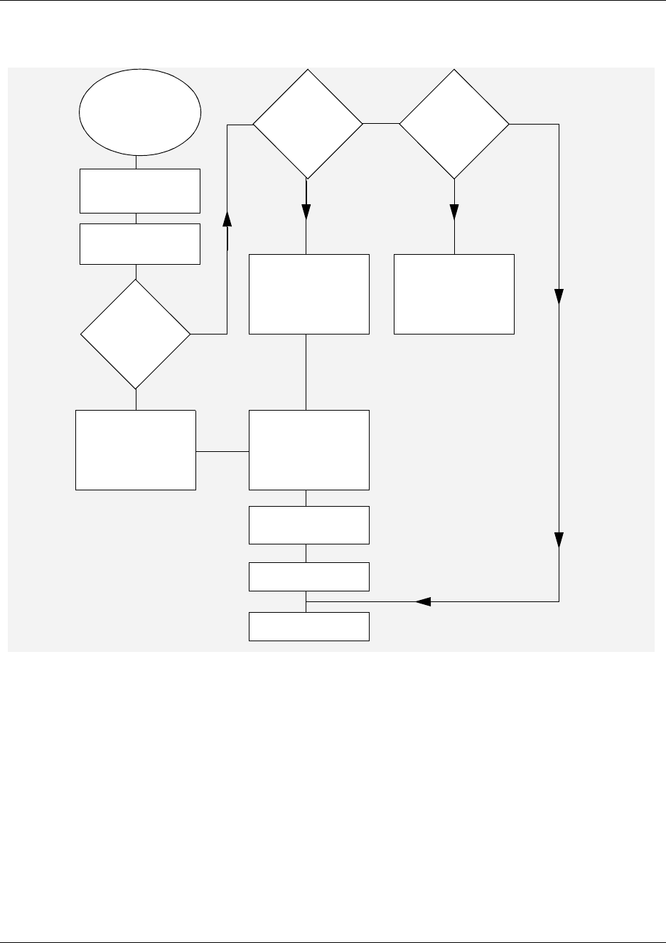
Chapter 6 Prepare Hardware for Maintenance or Upgrades 149
Installation and Maintenance Guide
Figure 79 Base function tray replacement overview
If possible,
do a software
shutdown
Perform BCM
maintenance
setup
No
Yes
Yes
No
Yes
Remove the base
function tray
Replace a
BFT card?
Replace
the BFT?
Remove the
old card.
Install the new
card in the
same BFT slot
See correct
replacement
procedure
No
Remove all cards.
Re-install all cards
in replacement
BFT
Insert the Base
function tray in the
BFT chassis cage
Restore unit to
operation
Check LEDs
Replace
different
component?
END
150 Chapter 6 Prepare Hardware for Maintenance or Upgrades
P0993133 03
Remove the base function tray
This procedure describes how to remove the base function tray to perform maintenance or
replacement activities.
Use the following steps to remove the base function tray from the platform base chassis:
1If you still have access to the Unified Manager, shut down the system using the Shutdown
command. For details refer to “Shut down the system software” on page 145. Otherwise, skip
to step 2.
2Set up the server for maintenance, as described in “Shut down the system hardware” on page
146.
3Disconnect the Business Communications Manager from the AC power outlet.
4Disconnect any connectors from the front of the base function tray.
5Attach one end of the grounding strap to your wrist and the other end to a grounded metal
surface.
6Remove the platform base chassis top cover. Refer to “Remove the platform base chassis top
cover” on page 161.
7Remove the base function tray latch screws and place in a safe location.
8Move the base function tray latches to the unlocked position. See Figure 80.
9Grasp the base function tray latches and partially remove the base function tray from the
platform base chassis. Do not exert force on the DS30 cables or connectors.
10 Disconnect DS30 cable connectors from the media services card. If necessary, remove the
WAN card to access the DS30 cables, see “Remove the WAN card” on page 219.
Warning: Protect the hardware components against damage from electro-static
discharge. Always wear a ground wriststrap before you handle components. Always place
the components in static-free container.
Warning: Use care when removing or inserting the Base function tray. Do not forcefully
remove or insert the base function tray. You could damage or stretch the cables.
Warning: Protect the hardware components against damage from electro-static
discharge. Always wear a ground wriststrap before you handle components. Always place
the components in static-free container.
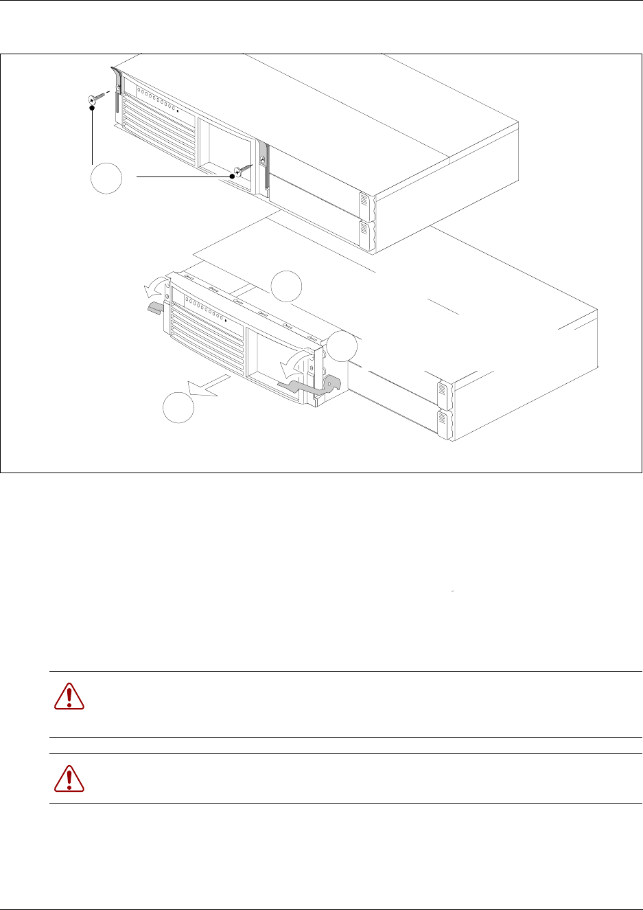
Chapter 6 Prepare Hardware for Maintenance or Upgrades 151
Installation and Maintenance Guide
Figure 80 Remove the base function tray
11 Remove the base function tray completely from the platform base chassis. Remove the base
function tray carefully to prevent damage to the cables and connectors.
12 Place the base function tray on a flat, clean and static-free surface.
13 This procedure is complete.
Install the base function tray
Use this procedure to insert the base function tray in the platform base chassis.
1Disconnect the Business Communications Manager from the AC power outlet.
2Attach one end of the grounding strap to your wrist and the other end to a grounded metal
surface.
Warning: Protect the hardware components against damage from electro-static
discharge. Always wear a ground wriststrap before you handle components. Always place
the components in static-free container or work area.
Warning: Use care when removing or inserting the Base function tray. Do not forcefully
remove or insert the base function tray. You could damage or stretch the cables.
Slide base function tray
partially away from the
platform base chassis
3
2Move base function tray latches to
the unlocked position
Disconnect DS30
cables from the MSC
Unfasten base function
tray latch screws
1
4
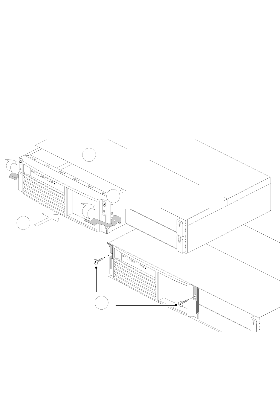
152 Chapter 6 Prepare Hardware for Maintenance or Upgrades
P0993133 03
3Move the base function tray latches to the unlocked position.
4Position the base function tray in the correct platform base chassis bay.
5Partially insert the base function tray into the platform base chassis (see Figure 81).
6Connect the DS30 connectors to the MSC. If necessary, install the WAN card (see “Install the
WAN card” on page 221 - return to this step when complete).
7If required, install the base function tray bezel (see “Install the base function tray bezel” on
page 154). Return to this step when complete.
8Push the base function tray completely into the chassis. Be careful not to crimp the DS30
cables.
9Move the base function tray latches to the locked position.
10 Install the base function tray latch screws.
Figure 81 Install the base function tray
11 Insert all connectors in the correct locations on the base function tray face.
12 Restore the Business Communications Manager system to operation. See: “Restart the System
after Maintenance” on page 147.
13 Observe the system status monitor LEDs to ensure the base function tray initializes correctly.
14 This procedure is complete.
Fasten base function
tray latch screws
4
Slide base function tray
partially into the platform
base chassis
1
3
2Connect DS30 cables
to the MSC
Insert base function tray completely.
Move base function tray latches to
the locked position

Chapter 6 Prepare Hardware for Maintenance or Upgrades 153
Installation and Maintenance Guide
Remove the base function tray bezel
Use this procedure to remove the base function tray bezel. Remove the base function tray bezel to
remove or install the PCI cover plate (during processor card removal or installation).
1If you still have access to the Unified Manager, shut down the system using the Shutdown
command. For details refer to “Shut down the system software” on page 145. Otherwise, skip
to step 2.
2Set up the server for maintenance, as described in “Shut down the system hardware” on page
146.
3Disconnect the Business Communications Manager from the AC power outlet.
4Disconnect any connectors from the front of the base function tray.
5Attach one end of the grounding strap to your wrist and the other end to a grounded metal
surface.
6Remove the base function tray latch screws and place in a safe location.
7Move the base function tray latches to the unlocked position. See Figure 80.
8Grasp the base function tray latches and partially remove the base function tray from the
platform base chassis. Do not exert force on the DS30 cables or connectors.
9Unfasten the bezel screws from the base function tray face. Place the screws in a safe location.
10 Pull and tip the bezel away from the base function tray until the bezel clips are clear of the
base function tray chassis. Move the bezel in a downward direction between the base function
tray latches. Place the bezel in a safe location. See Figure 82.
Warning: Protect the hardware components against damage from electro-static
discharge. Always wear a ground wriststrap before you handle components. Always place
the components in static-free container.
Warning: Use care when removing or inserting the Base function tray. Do not forcefully
remove or insert the base function tray. You could damage or stretch the cables.
Warning: Protect the hardware components against damage from electro-static
discharge. Always wear a ground wriststrap before you handle components. Always place
the components in static-free container.
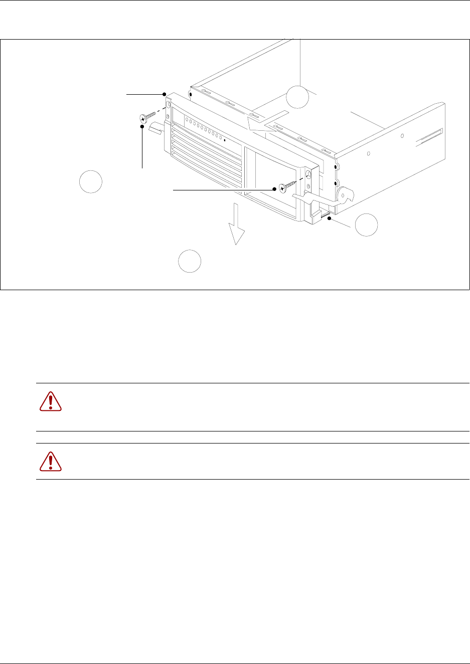
154 Chapter 6 Prepare Hardware for Maintenance or Upgrades
P0993133 03
Figure 82 Remove the base function tray bezel
11 This procedure is complete.
Install the base function tray bezel
Use this procedure to install the base function tray bezel.
1Disconnect the Business Communications Manager from the AC power outlet.
2Attach one end of the grounding strap to your wrist and the other end to a grounded metal
surface.
3Remove the base function tray latch screws (if applicable). Place the screws in a safe location.
4Move the base function tray latches to the unlocked position.
5Position the bezel below and between the base function tray latches. Lift the bezel until the
bezel clips line-up with the corresponding base function tray bezel holes.
6Tilt the bezel forward, then push the bottom of the bezel into the base function tray chassis to
engage the bezel clips.
Warning: Protect the hardware components against damage from electro-static
discharge. Always wear a ground wriststrap before you handle components. Always place
the components in static-free container or work area.
Warning: Use care when removing or inserting the Base function tray. Do not forcefully
remove or insert the base function tray. You could damage or stretch the cables.
Unfasten
Bezel screws
4
1
Move bezel downward
and between latches
Tip bezel away
from base
function tray
2
Bezel
Unhook bezel clips
from base function
tray chassis
3
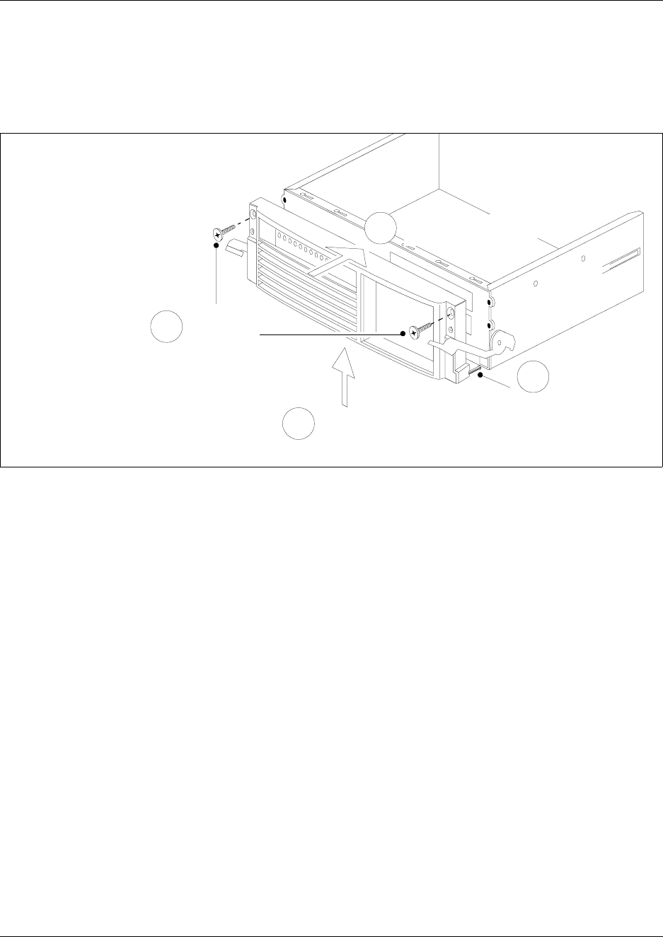
Chapter 6 Prepare Hardware for Maintenance or Upgrades 155
Installation and Maintenance Guide
7Push on the face of the bezel so that it rests flush with the face of the base function tray
chassis.
8Install the base function tray bezel screws. See Figure 83.
Figure 83 Install the base function tray bezel
9If required, install the base function tray in the platform base chassis. Refer to “Install the base
function tray” on page 151. Continue to the next step of this procedure when complete.
10 This procedure is complete.
Install Bezel
screws
4
Position bezel
between latches and
move upward
1
Insert bezel clips
into base function
tray chassis
3Push bezel against
base function tray
2
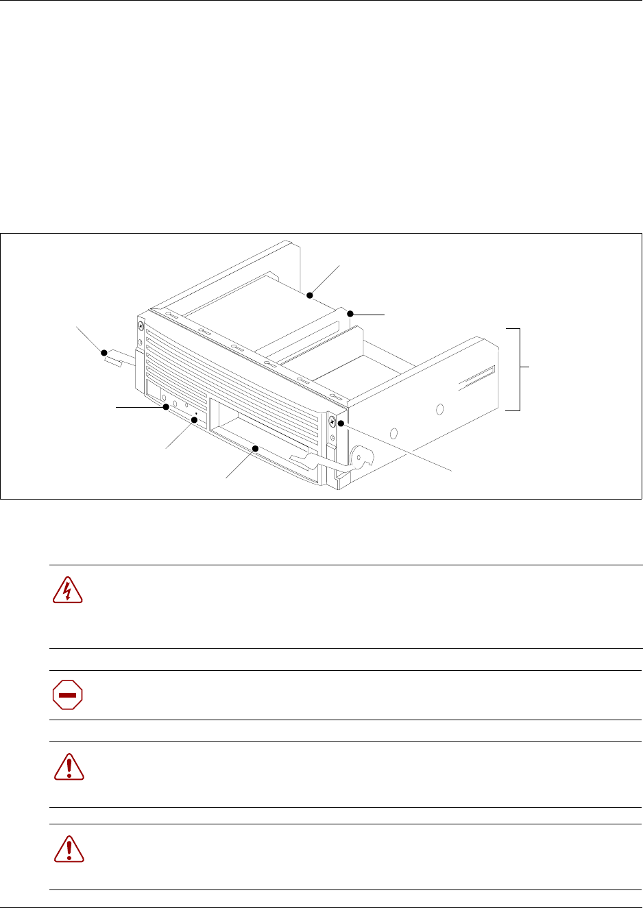
156 Chapter 6 Prepare Hardware for Maintenance or Upgrades
P0993133 03
Advanced Function Tray Maintenance Procedures
This procedure applies only to the BCM400 platform. This procedure describes how to remove
and install the advanced function tray in the platform base chassis. Use this procedure for
maintenance purposes.
The advanced function tray (AFT) houses the hard disk or RAID components for the BCM400
platform (see Figure 84). For further information see also “BCM400 advanced function tray
(AFT)” on page 50.
Figure 84 Advanced function tray
For information on how to replace the hard disk, refer to “Remove a hard disk cage from a
BCM400 platform base chassis” on page 168.
Danger: Electrical shock warning.
Disconnect the power cord, telephone cables and network cables before opening the
Business Communications Manager platform base chassis.
Read and follow installation instructions carefully.
Caution: Use only a Nortel Networks approved replacement. Contact your account
representative for the current list of approved replacement parts.
Warning: Use care when removing or inserting the advanced function tray. Do not
forcefully remove or insert the advanced function tray. You could damage or stretch the
cables.
Warning: Protect the hardware components against damage from electro-static
discharge. Always wear a ground wriststrap before you handle components. Always place
the components in static-free container or work area.
Advanced function
tray chassis
Status LEDs
(RAID only)
Reset button
Reserved bay
Advanced function
tray latch
Hard disk
Bezel screw
Hard disk cage
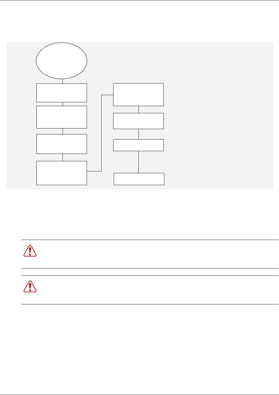
Chapter 6 Prepare Hardware for Maintenance or Upgrades 157
Installation and Maintenance Guide
Use the flow chart shown in Figure 85 as a summary guide to maintain the advanced function tray.
Figure 85 Advanced function tray replacement overview
Remove the advanced function tray
Use this procedure to remove the advanced function tray from the BCM400 platform base chassis.
1If you still have access to the Unified Manager, shut down the system using the Shutdown
command. For details refer to “Shut down the system software” on page 145. Otherwise, skip
to step 2.
2Set up the server for maintenance, as described in “Shut down the system hardware” on page
146.
3Disconnect the Business Communications Manager from the AC power outlet.
4Remove the platform base chassis top cover (see “Remove the platform base chassis top
cover” on page 161). Return to this step when complete.
Warning: Use care when removing or inserting the advanced function tray. Do not
forcefully remove or insert the advanced function tray. You could damage or stretch the
cables.
Warning: Protect the hardware components against damage from electro-static
discharge. Always wear a ground wriststrap before you handle components. Always place
the components in static-free container or work area.
If possible,
do a software
shutdown
Perform BCM
maintenance
setup
Remove the
advanced function
tray
Remove hard
disk.
Install new hard
disk in
replacement AFT
Insert the
advanced function
tray
Restore unit to
operation
Check LEDs
END
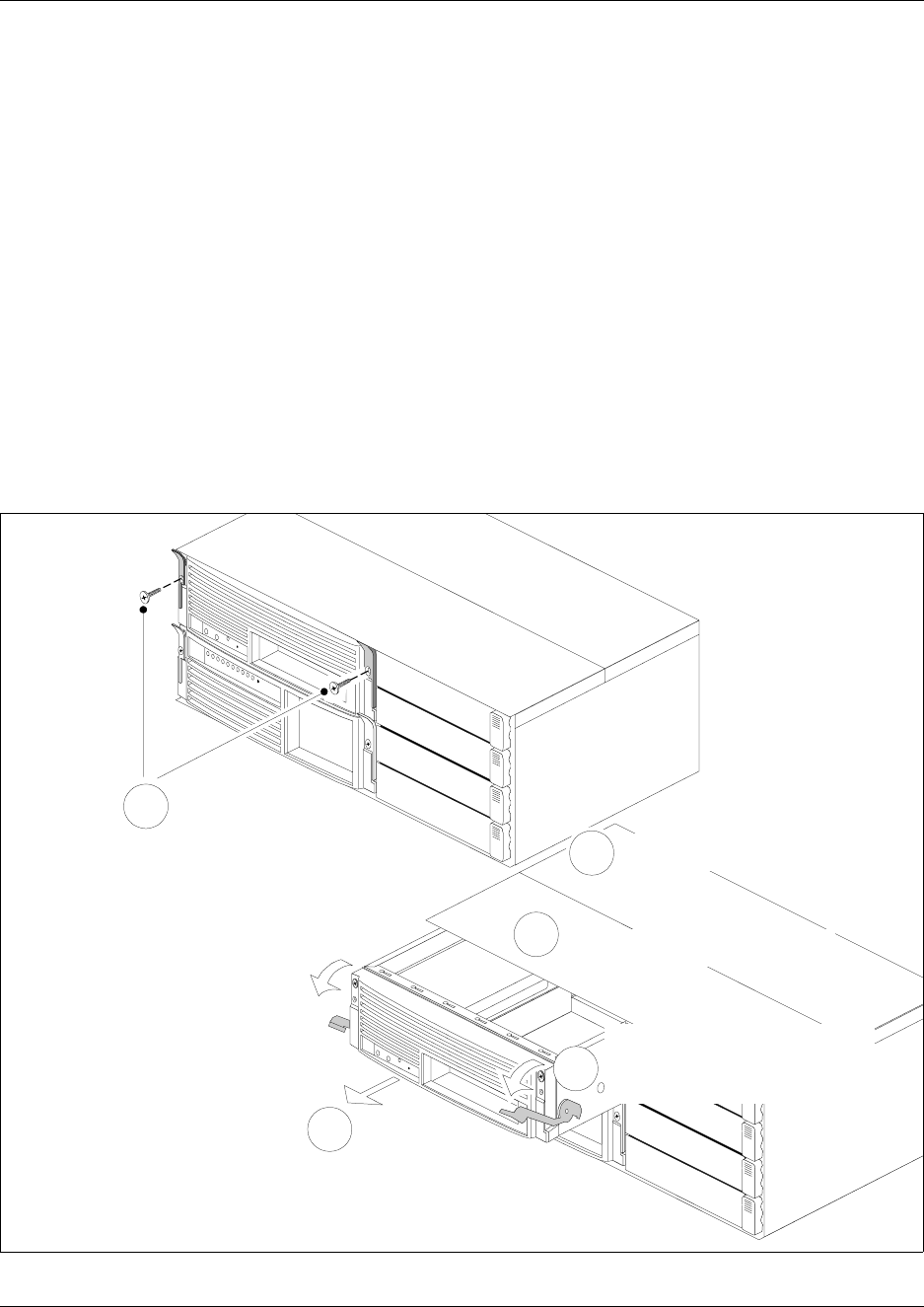
158 Chapter 6 Prepare Hardware for Maintenance or Upgrades
P0993133 03
5Attach one end of the grounding strap to your wrist and the other end to a grounded metal
surface.
6Remove the advanced function tray latch screws (see Figure 86). Place the screws in a safe
location.
7Move the advanced function tray latches to the unlock position.
8Grasp the advanced function tray latches and partially remove the unit from the platform base
chassis. Do not exert force on the hard disk power cables and connectors.
9Disconnect hard disk power cable connectors.
10 Disconnect the IDE connector.
11 Remove the advanced function tray completely from the platform base chassis.
12 Place the advanced function tray on a flat, clean and static-free surface. If you need to remove
the hard disk component, refer to See “Remove a hard disk cage from a BCM400 platform
base chassis” on page 168
Figure 86 Remove the advanced function tray
13 This procedure is complete.
Unfasten advanced
function tray latch screws
1
Slide advanced function tray partially
away from the platform base chassis
3
2
4
Disconnect IDE cable
from I/O card
5
Disconnect power cables from
the hard disk or RAID card
Move advanced function tray
latches to the unlocked position

Chapter 6 Prepare Hardware for Maintenance or Upgrades 159
Installation and Maintenance Guide
Install the advanced function tray
Use this procedure to install the advanced function tray in the platform base chassis.
1Disconnect the Business Communications Manager from the AC power outlet.
2Attach one end of the grounding strap to your wrist and the other end to a grounded metal
surface.
3Remove the platform base chassis top cover - see “Remove the platform base chassis top
cover” on page 161.
4Remove the advanced function tray latch screws. Place the screws in a safe location. If the
screws are already removed, skip to the next step.
5Move the advanced function tray latches to the unlocked position.
6Position the advanced function tray in the correct platform base chassis slot.
7Partially insert the advanced function tray into the platform base chassis (see Figure 87).
8Connect the hard disk power cable connectors. Use the first connector. Tuck any excess cable
under the hard disk.
9Connect the IDE connector.
10 Push the advanced function tray completely into the chassis. Be careful not to crimp the cables
(see Figure 87).
11 Move the advanced function tray latches to the locked position.
12 Install the advanced function tray latch screws.
13 Install the platform base chassis top cover. Refer to “Install the Platform Base Chassis Top
Cover” on page 163.
14 Restore the Business Communications Manager to operation. See: “Restart the System after
Maintenance” on page 147.
15 Observe the system status display LEDs to ensure the advanced function tray initializes
correctly.
Warning: Use care when removing or inserting the advanced function tray. Do not
forcefully remove or insert the advanced function tray. You could damage or stretch the
cables.
Warning: Protect the hardware components against damage from electro-static
discharge. Always wear a ground wriststrap before you handle components. Always place
the components in static-free container or work area.
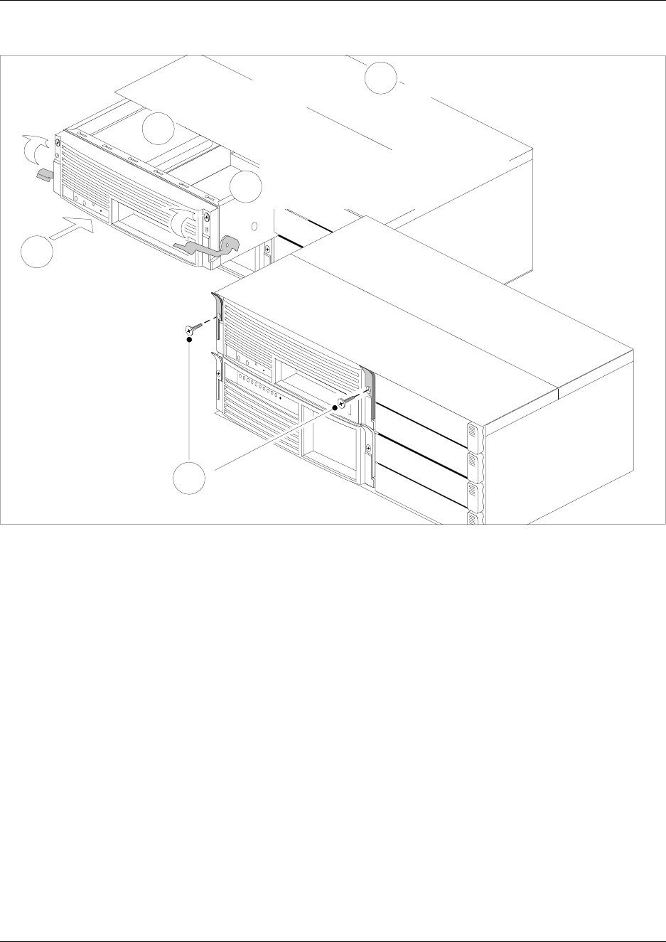
160 Chapter 6 Prepare Hardware for Maintenance or Upgrades
P0993133 03
Figure 87 Install the advanced function tray
16 This procedure is complete.
Install advanced
function tray latch
screws
5
Insert advanced
function tray
partially into the
platform base
chassis
1
2
Connect IDE cable to I/O card
3
4
Insert base function tray completely.
Move advanced function tray latches
to the locked position
Connect power cables to the
hard disk or RAID card
Chapter 6 Prepare Hardware for Maintenance or Upgrades 161
Installation and Maintenance Guide
Remove and Install the Platform Base Chassis Top Cover
Use the procedures in this section to either remove or install the top cover of the platform base
chassis. You must remove the top cover to access the cabling or hardware components such as
standard power supply, I/O card or backplanes.
Remove the platform base chassis top cover
Use this procedure to remove the top cover of the BCM200 or BCM400 platform base chassis.
This procedure assumes that you intend to perform maintenance activities. Do not operate the
Business Communications Manager with the top cover removed. Do not leave the top cover
removed for extended periods of time.
1If you still have access to the Unified Manager, shut down the system using the Shutdown
command. For details refer to “Shut down the system software” on page 145. Otherwise, skip
to step 2.
2Set up the server for maintenance, as described in “Shut down the system hardware” on page
146.
3Disconnect the Business Communications Manager from the AC power outlet.
4If required, remove the platform base chassis from the server rack.
5Attach one end of the grounding strap to your wrist and the other end to a grounded metal
surface.
6Remove the two top cover screws located at the rear of the platform base chassis. Place the
screws in a safe location.
7Lift the back of the cover and slide rear-ward until it disengages from the platform base
chassis. Refer to Figure 89 or Figure 89.
8Lift the top cover up and away from the platform base chassis. Place the cover in a safe
location.
Warning: Protect the hardware components against damage from electro-static
discharge. Always wear a ground wriststrap before you handle components. Always place
the components in static-free container or work area.
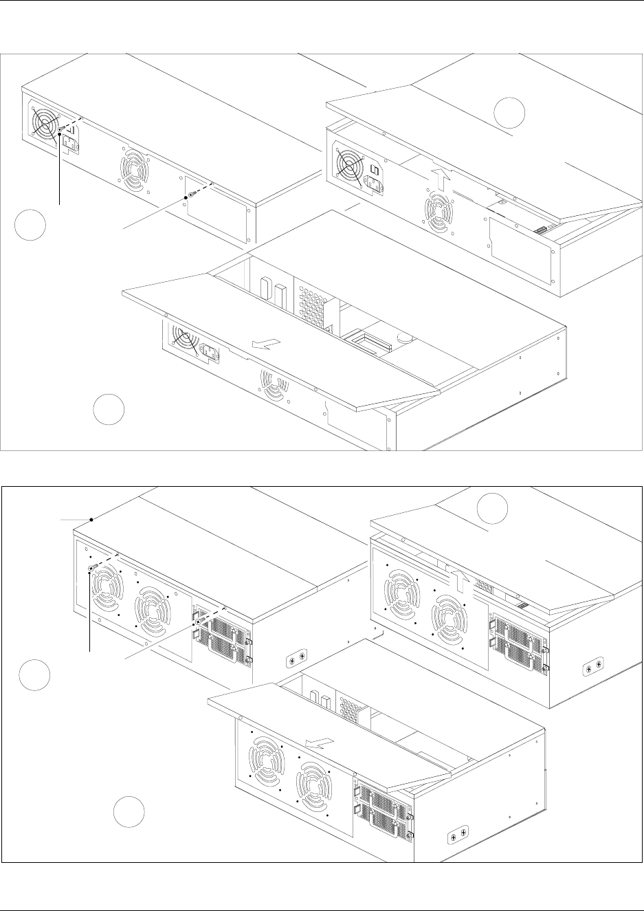
162 Chapter 6 Prepare Hardware for Maintenance or Upgrades
P0993133 03
Figure 88 Remove the BCM200 top cover
Figure 89 Remove the BCM400 top cover
9This procedure is complete.
Remove the
top cover
screws
3
1
Slide cover away
from chassis
Lift cover at rear
of chassis
2
Remove the
top cover
screws
Platform
chassis
top cover
Slide cover away
from chassis
1
3
Lift cover at rear
of chassis
2
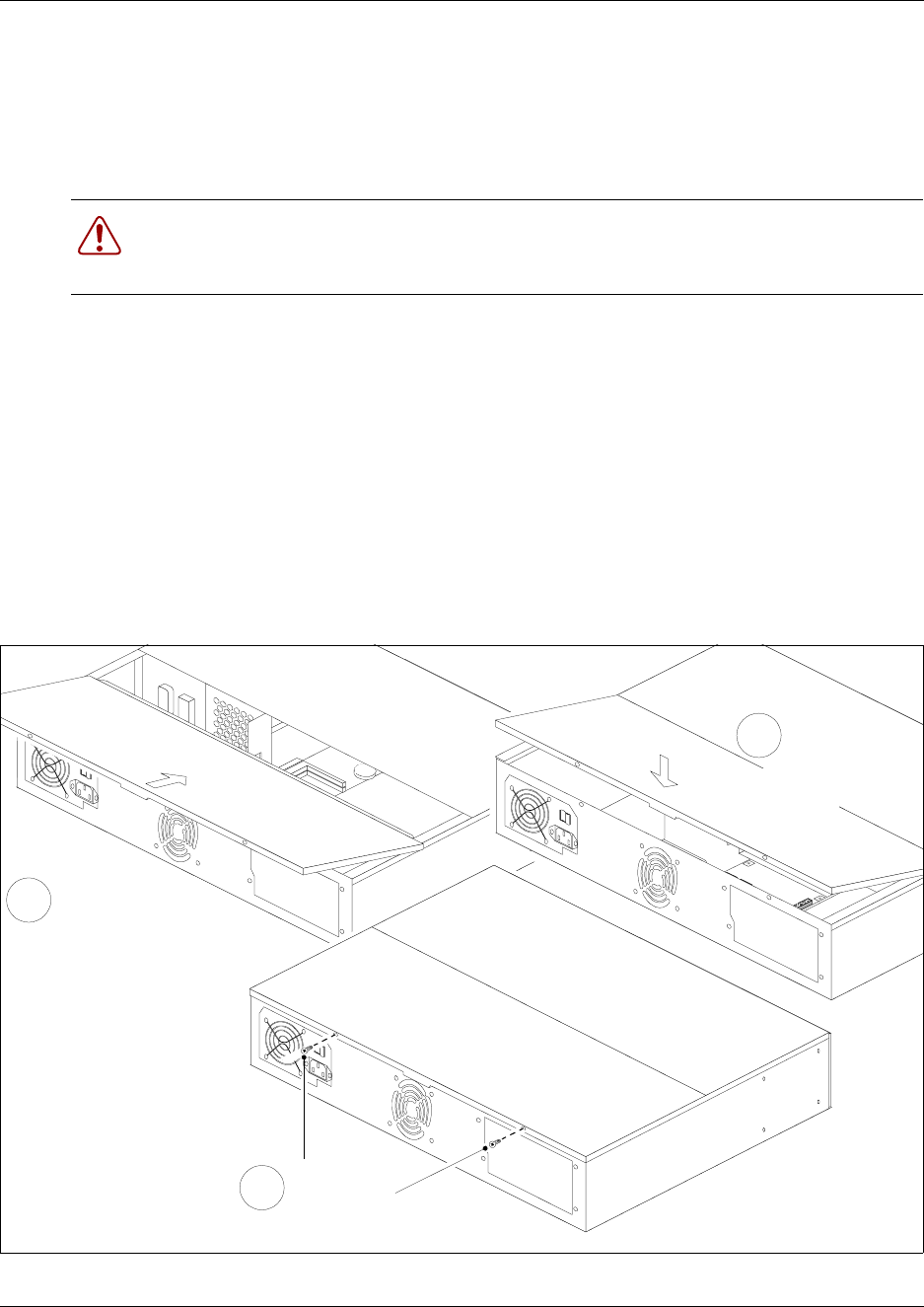
Chapter 6 Prepare Hardware for Maintenance or Upgrades 163
Installation and Maintenance Guide
Install the platform base chassis top cover
Use this procedure to install the top of the platform base chassis cover. This procedure assumes
that maintenance or installation activities are complete and that you are ready to start the Business
Communications Manager.
1Disconnect the Business Communications Manager from the AC power outlet.
2If required, remove the platform base chassis from the server rack.
3Attach one end of the grounding strap to your wrist and the other end to a grounded metal
surface.
4Set the top cover on the platform base chassis.
5Slide the top cover forward until the cover engages with the platform base chassis.
6Press the top cover down until it rests on the chassis. Refer to Figure 90 or Figure 91.
7Install the two top cover screws at the rear of the platform base chassis.
Figure 90 Install the BCM200 top cover
Warning: Protect the hardware components against damage from electro-static
discharge. Always wear a ground wriststrap before you handle components. Always place
the components in static-free container or work area.
Slide cover into
chassis
1
Press cover
down
2
Install the
top cover
screws
3
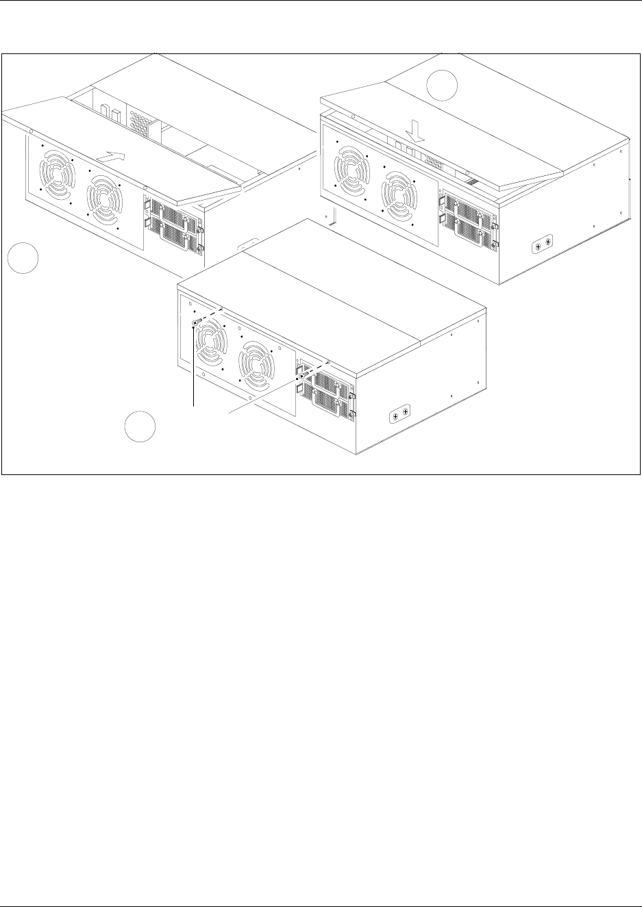
164 Chapter 6 Prepare Hardware for Maintenance or Upgrades
P0993133 03
Figure 91 Install the BCM400 top cover
8This procedure is complete.
Slide cover
into chassis
1
Press cover
down
2
Install the top
cover screws
3
165
Installation and Maintenance Guide
Chapter 7
Hard Disk Replacement Procedures
The hard disk is a core software and data storage component. For BCM200 platform base
configurations, the hard disk assembly installs at the rear of the platform base chassis. For
BCM400 platform base configurations, the hard disk assembly installs in the advanced function
tray (AFT) chassis.
The standard Business Communications Manager configuration includes one factory-installed
hard disk. The RFO Configuration includes 2 hard disks and RAID controller card. The field
upgrade includes a mirror hard disk and RAID controller card.
Use this procedure under the following conditions:
• if you need to replace an existing hard disk
• if you need to upgrade to RAID
Remember to take suitable precautions when working inside the Business Communications
Manager system. Maintain a clean and static-safe site.
Danger: Electrical shock warning.
Disconnect the power cord, telephone cables and network cables before opening the
Business Communications Manager platform base chassis. Read and follow installation
instructions carefully.
Caution: Use only a Nortel Networks approved replacement. Contact your account
representative for the current list of approved replacement parts.
Warning: Maintain a current backup of your system.
When you replace the hard disk, you must restore the Business Communications
Manager system programming from the backup.
Caution: Do not use an electric screwdriver near the hard disk. You can lose the
information stored on the disk. Shock can damage the hard disk. Do not drop or
hit the hard disk drive.
Warning: You must remove all of the connections to the Business Communications
Manager base function tray before you power the system down.
Failure to disconnect lines before power down can cause damage to the system.
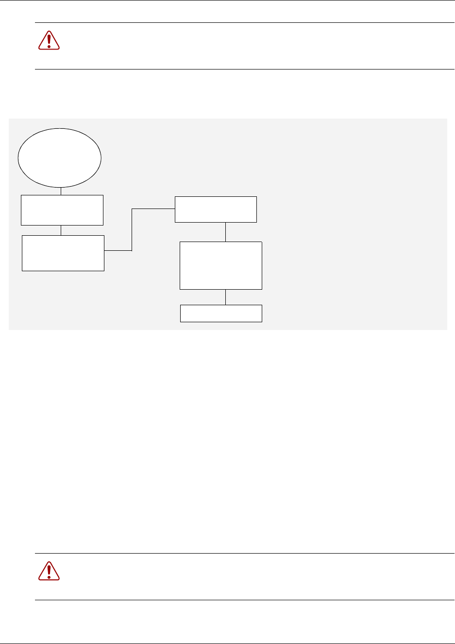
166 Chapter 7 Hard Disk Replacement Procedures
P0993133 03
Figure 92 provides an overview of the hard disk replacement process.
Figure 92 Hard disk replacement overview
Remove a Hard Disk
When a hard disk is causing problems or fails, you must remove the unit from the BCM200 base
platform chassis or the BCM400 advanced function tray. This section describes two processes to
remove a hard disk:
• Remove a hard disk cage (containing the hard disk)
• Remove a hard disk (from the hard disk cage)
Remove a hard disk cage from a BCM200 platform base chassis
Use this procedure to remove the hard disk cage from the BCM200 base platform chassis. Use this
procedure to remove a BCM200 RAID upgrade kit.
1If you still have access to the Unified Manager, shut down the system by following the
instructions in “Shut down the system software” on page 145. Otherwise, skip to step 2.
Warning: Protect the hardware components against damage from electro-static
discharge. Always wear a ground wriststrap before you handle components. Always place
the components in static-free container.
Warning: Protect the hardware components against damage from electro-static
discharge. Always wear a ground wriststrap before you handle components. Always place
the components in static-free container.
If possible,
do a software
shutdown
Set up unit for
maintenance
Remove the hard
disk and replace
with new disk
Restore unit to
operation
Test all functions
Perform system
initialization and a
BRU data restore
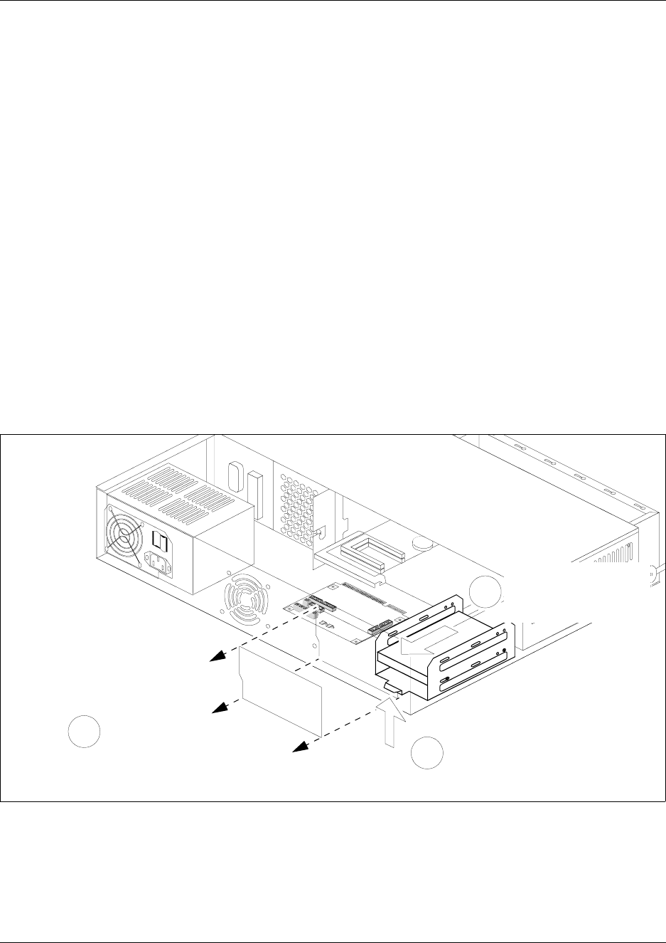
Chapter 7 Hard Disk Replacement Procedures 167
Installation and Maintenance Guide
2Set up the server for maintenance, as described in “Shut down the system hardware” on page
146. Continue to the next step of this procedure when complete.
3Disconnect the Business Communications Manager from the wall power outlet.
4Attach one end of the grounding strap to your wrist and the other end to a grounded metal
surface.
5Access the hard disk from a panel at the rear of the platform base chassis. Remove the four
hard disk access panel screws (see Figure 4 on page 45). Place the panel and screws in a safe
location.
6Remove the BCM200 platform base chassis top cover (see “Remove the platform base chassis
top cover” on page 161). Continue to the next step of this procedure when complete.
7Place your fingers under the tab located at the bottom rear of the hard disk cage. Lift firmly on
the tab. At the same time, slide the hard disk cage in the direction shown in Figure 93 until the
unit detaches from the mounting points on the chassis.
8Disconnect the hard disk from the system:
aDisconnect the power supply connector from the hard disk.
bDisconnect the hard disk connector at the I/O card.
Figure 93 Detach the hard disk cage from the BCM200 platform base chassis
9Remove the hard disk cage from the BCM200 platform base chassis. Place the hard disk cage
on a flat, clean and static-free surface.
10 This procedure is complete.
Lift hard disk cage tab
2
Slide the hard disk
cage toward the rear
of the chassis
3
Remove access panel
1

168 Chapter 7 Hard Disk Replacement Procedures
P0993133 03
Remove a hard disk cage from a BCM400 platform base chassis
Use this procedure to remove the hard disk cage from the BCM400 advanced function tray. Use
this procedure to remove a BCM400 RAID upgrade kit.
1If you still have access to the Unified Manager, shut down the system by following the
instructions in “Shut down the system software” on page 145. Otherwise, skip to step 2.
2Set up the server for maintenance, as described in “Shut down the system hardware” on page
146. Continue to the next step of this procedure when complete.
3Disconnect the Business Communications Manager from the AC power outlet.
4Attach one end of the grounding strap to your wrist and the other end to a grounded metal
surface.
5Partially remove the BCM400 advanced function tray (see “Remove the advanced function
tray” on page 157). Do not to pinch or stretch any cables when sliding the advanced function
tray partially out of the platform base chassis.
6Locate the hard disk in the advanced function tray.
7Disconnect the hard disk cables from the system:
aDisconnect the power supply connector from the hard disk.
bDisconnect the hard disk connector at the I/O card.
8Carefully remove the advanced function tray. Do not pinch or stretch any cables when sliding
the advanced function tray completely out of the platform base chassis.
9Remove the transportation HDD cage restraint screw and keep in a safe place.
10 Place your fingers under the tab located at the bottom rear of the hard disk cage. Lift firmly on
the tab. At the same time, slide the hard disk cage in the direction shown in Figure 94 until the
unit detaches from the mounting points on the chassis.
Warning: Protect the hardware components against damage from electro-static
discharge. Always wear a ground wriststrap before you handle components. Always place
the components in static-free container.
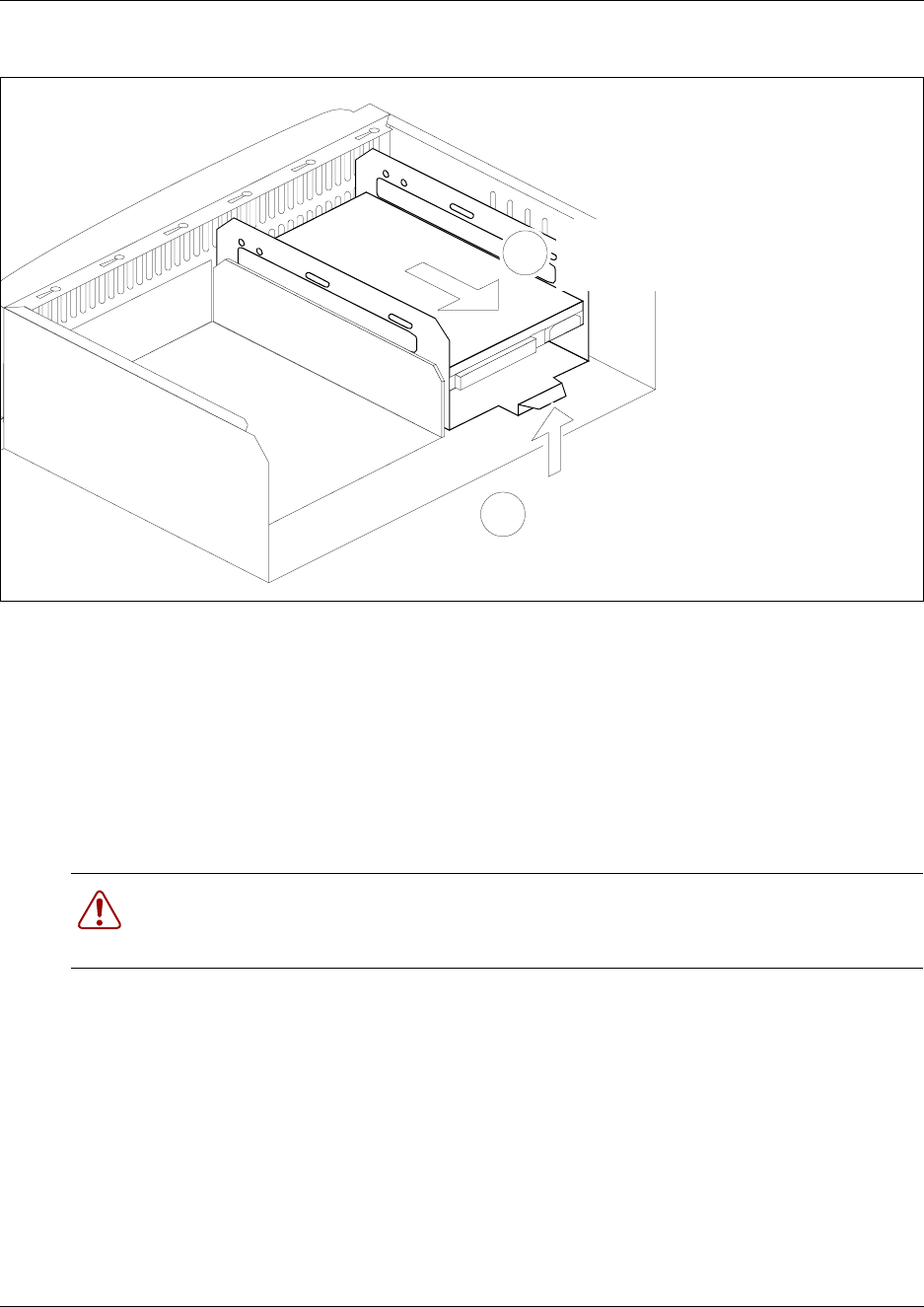
Chapter 7 Hard Disk Replacement Procedures 169
Installation and Maintenance Guide
Figure 94 Detach the hard disk cage from the BCM400 advanced function tray chassis
11 Remove the hard disk cage from the BCM400 advanced function tray chassis. Place the hard
disk cage on a flat, clean and static-free surface.
12 This procedure is complete.
Remove a hard disk from the hard disk cage
Use this procedure to remove the hard disk from the hard disk cage. Use this procedure also to
remove hard disks from a BCM200 or BCM400 RAID upgrade unit.
1Remove the hard disk cage from the chassis (see “Remove a Hard Disk” on page 166).
Continue to the next step in this procedure when complete.
2Unscrew the hard disk retainer screws from both sides of the hard disk cage. Place the retainer
screws in a safe location (see Figure 95).
3Remove the hard disk from the hard disk cage. Place the hard disk on a flat, clean and
static-free surface.
Warning: Protect the hardware components against damage from electro-static
discharge. Always wear a ground wriststrap before you handle components. Always place
the components in static-free container.
Lift hard disk cage tab
1
2Slide the hard disk cage toward
the rear of the advanced function
tray chassis
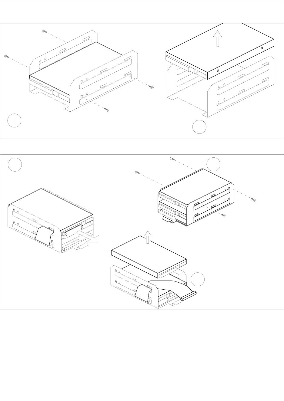
170 Chapter 7 Hard Disk Replacement Procedures
P0993133 03
Figure 95 Remove the hard disk from the hard disk cage
Figure 96 Remove the primary hard disk from the RAID hard disk cage
4This procedure is complete.
Remove the hard
disk retainer screws Remove the hard disk
from the hard disk cage
12
Remove the hard
disk retainer screws
Remove the hard disk
from the hard disk cage
2
3
Rear view
Disconnect the primary hard
disk ribbon cable from the
primary hard disk
1
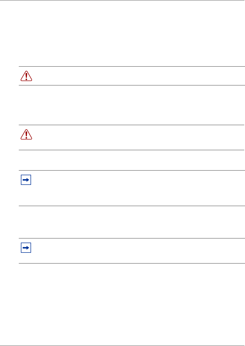
Chapter 7 Hard Disk Replacement Procedures 171
Installation and Maintenance Guide
Install a New Hard Disk
This section describes the procedures to install a new hard disk into the Business Communications
Manager. This section describes two processes to install a hard disk:
• Install a hard disk (into the hard disk cage)
• Install a hard disk cage (containing the hard disk) into the platform base chassis
Install a hard disk into a hard disk cage
Use this procedure to install a hard disk into a hard disk cage for a BCM200 or BCM400 platform.
1Position the hard disk into the hard disk cage.
2Align the hard disk and hard disk cage retaining screw holes. Fasten the hard disk cage retainer
screws into both sides of the hard disk cage (see Figure 97 or Figure 98).
Warning: You must initialize the Business Communications Manager system when you
install a new hard disk on a single-disk system.
Warning: Protect the hardware components against damage from electro-static
discharge. Always wear a ground wriststrap before you handle components. Always place
the components in static-free container.
Note: For a BCM200 platform, orient the hard disk such that the power and IDE
connectors are on the bottom and opposite to the hard disk cage lift tab (see Figure 97).
For a BCM400 platform, orient the hard disk such that the power and IDE connectors are
on the bottom and on the same side as the hard disk cage lift tab (see Figure 98).
Note: For a RAID upgrade kit, the mirror disk and primary disk ribbon cables are
pre-installed. If applicable, install the programmed hard disk from your single disk system
into the RAID hard disk cage (see Figure 98).
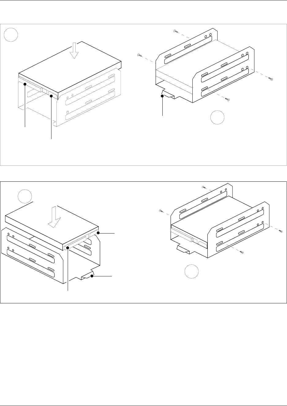
172 Chapter 7 Hard Disk Replacement Procedures
P0993133 03
Figure 97 Install a BCM200 hard disk in the hard disk cage
Figure 98 Install a BCM400 hard disk in the hard disk cage
Align and install the
hard disk retainer
screws
Insert the hard disk into
the hard disk cage
1
2
Front view
Rear view
Hard disk
cage lift
tab
IDE
connector
Power
supply
connector
IDE connector
Hard disk
cage lift
tab
Insert the hard disk into
the hard disk cage
1
Power
supply
connector
2Align and install the hard
disk retainer screws
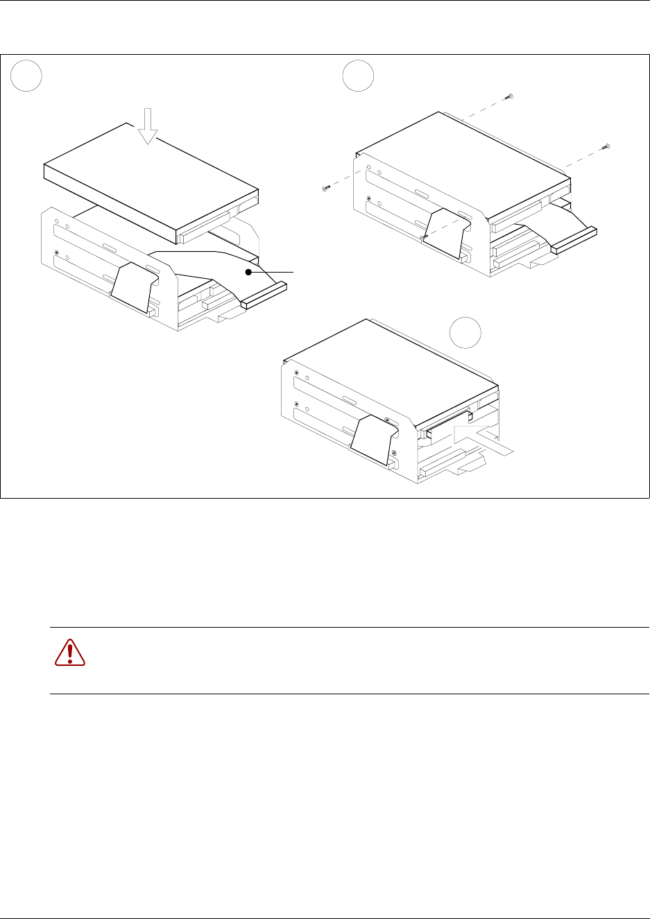
Chapter 7 Hard Disk Replacement Procedures 173
Installation and Maintenance Guide
Figure 99 Install the programmed hard disk into the RAID hard disk cage
3This procedure is complete.
Install a hard disk cage in a BCM200 platform base chassis
Use this procedure to install the hard disk cage into the BCM200 platform base chassis.
1Disconnect the Business Communications Manager from the AC power outlet.
2Attach one end of the grounding strap to your wrist and the other end to a grounded metal
surface.
3Remove the platform base chassis top cover (see “Remove the platform base chassis top
cover” on page 161).
4You can access the hard disk location from a panel at the rear of the platform base chassis.
Remove the four hard disk access panel screws (see Figure 93). Place the panel and screws in
a safe location.
5Install the hard disk in the hard disk cage.
Warning: Protect the hardware components against damage from electro-static
discharge. Always wear a ground wriststrap before you handle components. Always place
the components in static-free container.
Install the programmed (primary) hard
disk into the hard disk cage
1
Connect the primary
hard disk ribbon cable
to the primary hard disk
3
Rear view
Rear view
Install the hard disk retaining screws
2
Primary
hard disk
ribbon
cable
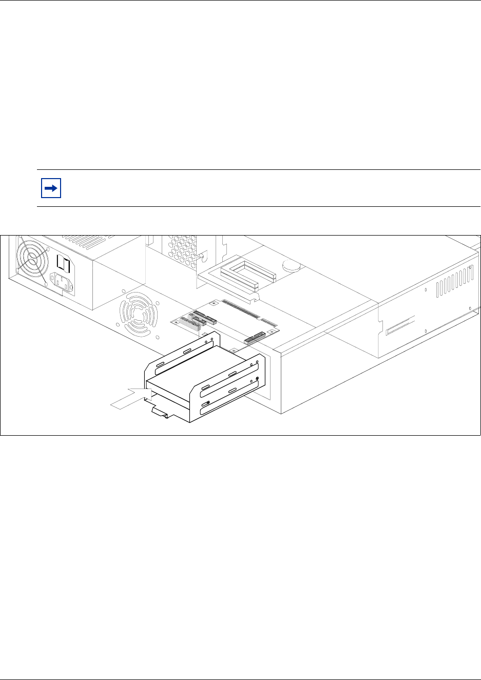
174 Chapter 7 Hard Disk Replacement Procedures
P0993133 03
aInsert the hard disk cage through the hard disk access panel in the back of the BCM200.
bPosition the hard disk cage in front of the cage chassis mounting points. The hard disk
cage lift tab is at the rear of the hard disk cage.
cSlide the hard disk cage in the direction shown in Figure 100 until the unit attaches to the
chassis. You will hear and feel a snap as the locking tab slips into position.
6Reconnect power and IDE cables to the hard disk. Connect the hard disk to the system:
aConnect the hard disk I/O card connector to the I/O card IDE interface.
bConnect the power supply to the hard disk.
Figure 100 Insert the hard disk cage into the BCM200 platform base chassis
7Replace the cover and access panel (if required).
8Restore the Business Communications Manager to operation. Refer to “Restart the System
after Maintenance” on page 147.
9Set up the disk:
aInitialize the hard disk. Refer to “Initialize the Hard Disk” on page 176.
bAfter the disk is initialized, restore your data from your backups. If you did not backup
your keycodes, re-enter them (see “Enter the software keycodes” on page 142).
10 This procedure is complete.
Note: All connectors have a notch that allows you to align the connectors correctly.
If you cannot push a connector in easily, do not force it.
Slide the hard disk
cage toward the front
of the chassis
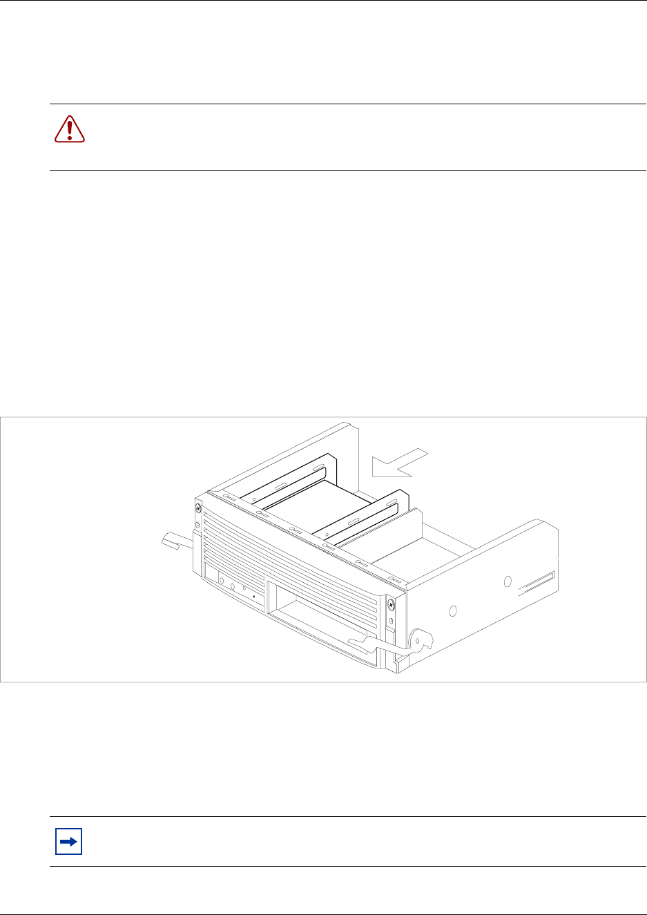
Chapter 7 Hard Disk Replacement Procedures 175
Installation and Maintenance Guide
Install a hard disk cage in a BCM400 platform base chassis
Use this procedure to install the hard disk cage into the BCM400 platform advanced function tray.
1Disconnect the Business Communications Manager from the AC power source.
2Attach one end of the grounding strap to your wrist and the other end to a grounded metal
surface.
3Install the hard disk in the hard disk cage (see “Install a hard disk into a hard disk cage” on
page 171).
4Position the hard disk cage in front of the cage chassis mounting points in the advanced
function tray. The hard disk cage lift tab is at the rear of the hard disk cage.
5Slide the hard disk cage in the direction shown in Figure 101 until the unit engages with the
chassis mounting points in the advanced function tray.
Figure 101 Insert the hard disk cage to the BCM400 advanced function tray chassis
6Partially insert the advanced function tray into the BCM400 platform base chassis. Ensure you
do not pinch any cables against the chassis or internal components.
7Connect the hard disk to the system:
aConnect the hard disk to the IDE interface ribbon cable.
bConnect the power supply to the hard disk.
Warning: Protect the hardware components against damage from electro-static
discharge. Always wear a ground wriststrap before you handle components. Always place
the components in static-free container.
Note: All connectors have a notch that allows you to align the connectors correctly.
If you cannot push a connector in easily, do not force it.
Lift and slide the hard disk cage
toward the front of the AFT chassis
Insert hard disk cage

176 Chapter 7 Hard Disk Replacement Procedures
P0993133 03
8Slide the advanced function tray completely into the BCM400 platform base chassis (see
“Install the advanced function tray” on page 159).
9Restore the Business Communications Manager to operation. Refer to “Restart the System
after Maintenance” on page 147.
10 Set up the hard disk:
aInitialize the hard disk. Refer to “Initialize the Hard Disk” on page 176.
bAfter the disk is initialized, restore your data from your backups. If you did not backup
your keycodes, re-enter them.
11 This procedure is complete.
Initialize the Hard Disk
The Business Communications Manager system is normally initialized prior to shipment.
However, if you have to replace the hard drive in a Business Communications Manager, you must
re-initialize the Business Communications Manager.
After you replace the hard disk and the system has booted up, perform the initialization as follows:
1Make sure the Status LED on the Business Communications Manager is lit. This LED that all
services have started and the Business Communications Manager is operating correctly.
2Attach the base function tray and a computer through the serial port, as described in “Null
modem cable setup” on page 138.
3Enter the terminal emulation program, as described in “Display the configuration menus” on
page 139,
•If the hard disk does not require initialization, the main menu appears. Refer to Figure 102.
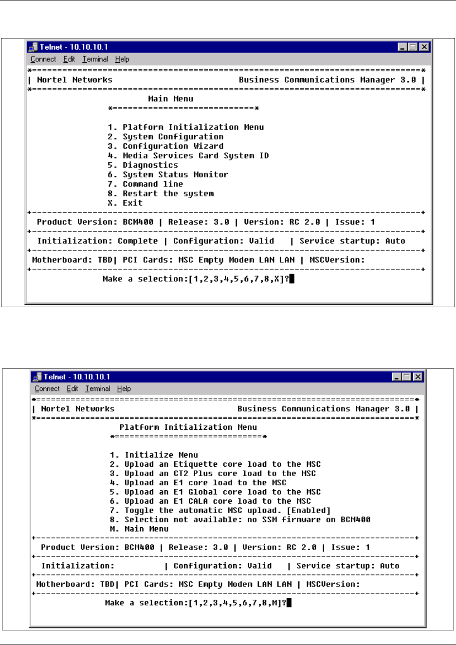

178 Chapter 7 Hard Disk Replacement Procedures
P0993133 03
4Enter the number beside the upload for the software you want to install. If you do not know
which software to upload, refer to “Core Software and Regions” on page 299.
5Ensure the correct MSC configuration has been entered.
Enter 1 (Select the hardware profile for this unit).
6The current MSC configuration is indicated on screen.
If you want to change this, make a different selection from the Platform Initialization
menu. The system checks to see if a core upload is required. This takes about 10 minutes.
If you do not want to change the MSC load, enter the number of the selection with the
asterisks.
7The system automatically reboots a number of times as part of the initialization process. When
the first reboot occurs, the telnet session disconnects.
8Do one of the following:
•Run the Quick Start Wizard to create the system parameters and defaults. Then restore your
system data from your data backup.
•Restore system and data information from your backup data.
9This procedure is complete.
Note: The detailed processes for performing steps 6 and 7 are contained in the Business
Communications Manager 3.0 Programming Operations Guide.
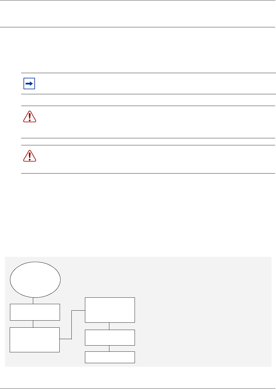
179
Installation and Maintenance Guide
Chapter 8
Install or Replace a Cooling Fan
This chapter describes how to replace a cooling fan in the BCM200 and BCM400 platform base
chassis. This chapter also describes how to add a second fan the BCM400 platform base chassis
(available through the field redundancy upgrade kit).
Cooling Fan Replacement Process
Cooling fans circulate air through the chassis of the Business Communications Manager platform
base chassis and expansion unit to prevent the components from overheating.
Figure 104 provides an overview of the fan replacement process.
Figure 104 Chassis cooling fan replacement overview
Note: For the BCM400 RFO factory configuration, a redundant cooling fan and power
supply is included.
Warning: You must remove all of the connections to the Business Communications
Manager platform base chassis before you power the system down.
Failure to disconnect lines before power down can cause damage to the system.
Warning: Protect the hardware components against damage from electro-static
discharge. Always wear a ground wriststrap before you handle components. Always place
the components in static-free container.
Set up unit for
maintenance
Install new fan.
Connect fan
cables to power
Restore unit to
operation
Check fan LED
FAN LED and/
or temp. LED
indicate
problem
Disconnect and
remove failed
fan
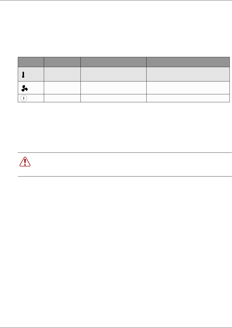
180 Chapter 8 Install or Replace a Cooling Fan
P0993133 03
Troubleshooting Fans
There are three LEDs on the front of the Business Communications Manager base function tray
and one on the front of the expansion unit used to assess fan function. Table 23 describes the
possible states of the fan and temperature LEDs.
Remove a BCM400 cooling fan
Use this procedure to remove the cooling fan(s) in a BCM400 standard or redundant feature option
(RFO) platform configuration. The standard Business Communications Manager platform base
chassis has one fan. The BCM400 RFO version has two fans.
Before you shut down the system, determine if a fan (in the redundant version) has failed. Refer to
Table 23.
1If you still have access to the Unified Manager, shut down the system using the Shutdown
command. For details refer to “Shut down the system software” on page 145. Otherwise, skip
to the next step.
2Set up the Business Communications Manager for maintenance, as described in “Shut down
the system hardware” on page 146.
3Disconnect the Business Communications Manager system from the AC power outlet.
4Attach one end of the grounding strap to your wrist and the other end to a grounded metal
surface.
5Remove the fan access panel at the rear of the platform base chassis (see Figure 105):
aRemove the fan access panel screws at the top and bottom of the panel. Place the screws in
a safe location.
bTip the top of the fan access panel toward you.
cGrasp the fan access panel with both hands and lift the away from the platform base
chassis. Do not stretch the fan cable(s).
Table 23 Fan and temperature LEDs on the base function tray
LED Label Description Green LED On Red LED On (Only)
Temperature Temperature is below threshold. Temperature is in alarm status.
Possible fan(s) failure.
Fans All installed fans are working There is a problem with a minimum of
one fan.
Power All components are working Component failure
Warning: Protect the hardware components against damage from electro-static
discharge. Always wear a ground wriststrap before you handle components. Always place
the components in static-free container.
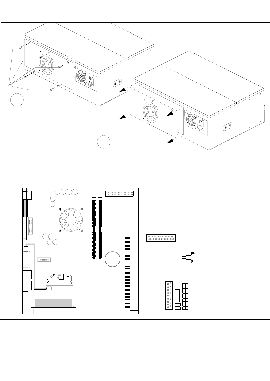
Chapter 8 Install or Replace a Cooling Fan 181
Installation and Maintenance Guide
Figure 105 Remove the BCM400 fan access panel
6Disconnect the I/O card fan cable(s) - see Figure 106. For the BCM400 RFO configuration,
disconnect both fan cables from the I/O card.
Figure 106 Disconnect the fan cable from the I/O card
7Remove the snap rivets that hold the fan to the fan access panel. The snap rivet has two parts;
a center pin and a collar. Gently separate the plastic rivet pin with your fingernails from the
center of the rivet collar. Remove the rivet pin and collar from the fan access panel. Place the
rivet pin and collar in a safe location.
Remove fan access
panel screws
1
Remove fan access
panel
2
I/O Card
Main Card
Disconnect from
single fan (fan #1)
Disconnect from
redundant fan (fan #2)
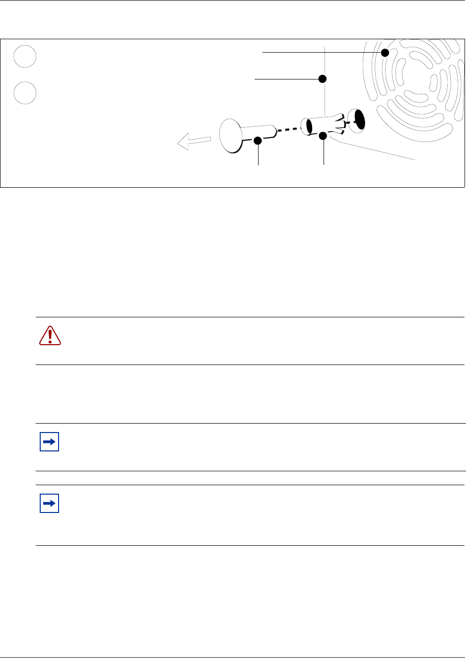
182 Chapter 8 Install or Replace a Cooling Fan
P0993133 03
Figure 107 Remove the snap rivets from the BCM400 fan access panel
8Lift the fan away from the fan access panel and place it in a safe location.
9Repeat Steps 7 and 8 to remove the redundant fan on the BCM400 RFO configuration.
10 This procedure is complete.
Install a BCM400 cooling fan
Use this procedure to install a single or redundant cooling fan in a BCM400 platform base chassis.
1Place the new fan in the fan access panel in the position from which you removed the old fan.
Ensure the I/O card connector cable is oriented to the bottom of the fan and that the fan label is
closest to the grill on the panel.
2Attach the fan to the fan access panel using the four plastic rivets.
aAlign the fan chassis mounting holes with the holes in the fan access panel (see Figure
108).
Warning: Protect the hardware components against damage from electro-static
discharge. Always wear a ground wriststrap before you handle components. Always place
the components in static-free container.
Note: Ensure the label of the new fan faces the back wall of the Business
Communications Manager platform base chassis. Airflow is out of the chassis as indicated
by the arrows imprinted on the fan.
Note: Redundant feature option (dual fans)
If you are installing a second fan, you must use the new fan access panel (included with
the redundant feature option kit) on the back of the Business Communications Manager
platform base chassis. The redundant fan access panel has two fan exhausts.
fan access panel
Rivet pin Rivet collar
Fan exhaust
Remove the rivet collar
from the fan access panel
Remove the rivet pin from
the rivet collar.
2
1
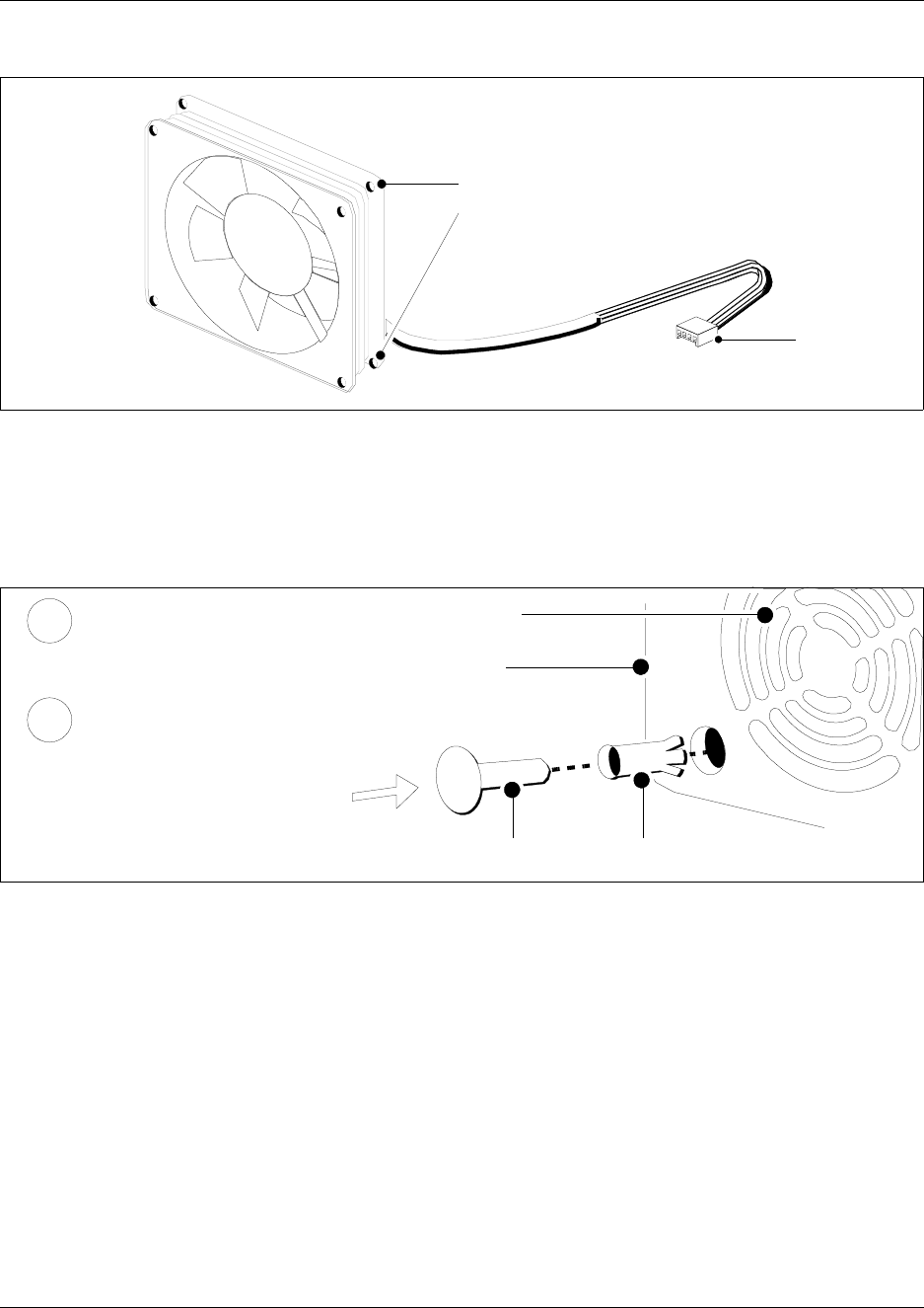
Chapter 8 Install or Replace a Cooling Fan 183
Installation and Maintenance Guide
Figure 108 Fan chassis mounting holes
bHold the fan in place against the fan access panel. Push the rivet collar through the fan
access panel and fan chassis mounting holes.
cInsert the rivet pin into the rivet collar. Repeat this step for the second fan in the BCM400
RFO configuration (see Figure 109).
Figure 109 Insert the snap rivets into the BCM400 fan access panel
3Connect the power supply cables for each fan to the I/O card (see Figure 110):
aConnect Fan #1 (fan farthest from the power supply) to connector #1 on the I/O card.
bConnect Fan #2 (fan closest to the power supply) to connector #2 on the I/O card.
Chassis mounting
holes
I/O card fan
connector
fan access panel
Rivet pin Rivet collar
Insert the rivet collar into
the fan access panel hole.
Insert the rivet pin into the
rivet collar.
Fan exhaust
1
2
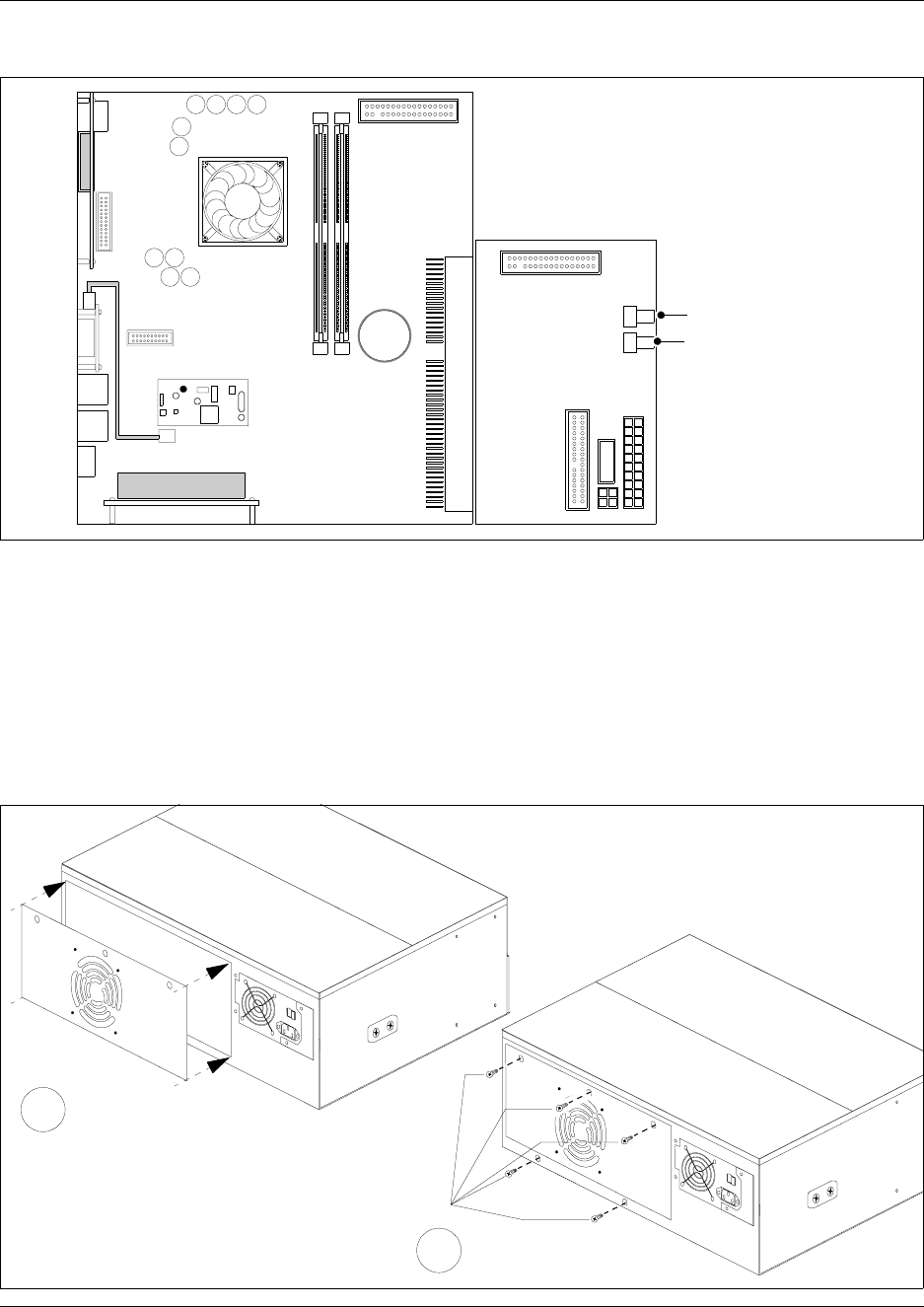
184 Chapter 8 Install or Replace a Cooling Fan
P0993133 03
Figure 110 Connect the fan cable(s) to the I/O card
4Mount the fan access panel to the platform base chassis (see Figure 111):
aTip the top of the fan access panel toward you.
bInsert the bottom lip of the fan access panel in the platform base chassis.
cAlign the screw holes in the fan access panel with the screw holes on the platform base
chassis.
dInstall and tighten the fan access panel screws.
Figure 111 Install the fan access panel to the platform base chassis
I/O Card
Main Card
Connect to single
fan (fan #1)
Connect to redundant
fan (fan #2)
Install fan access
panel screws
Install fan access panel
2
1
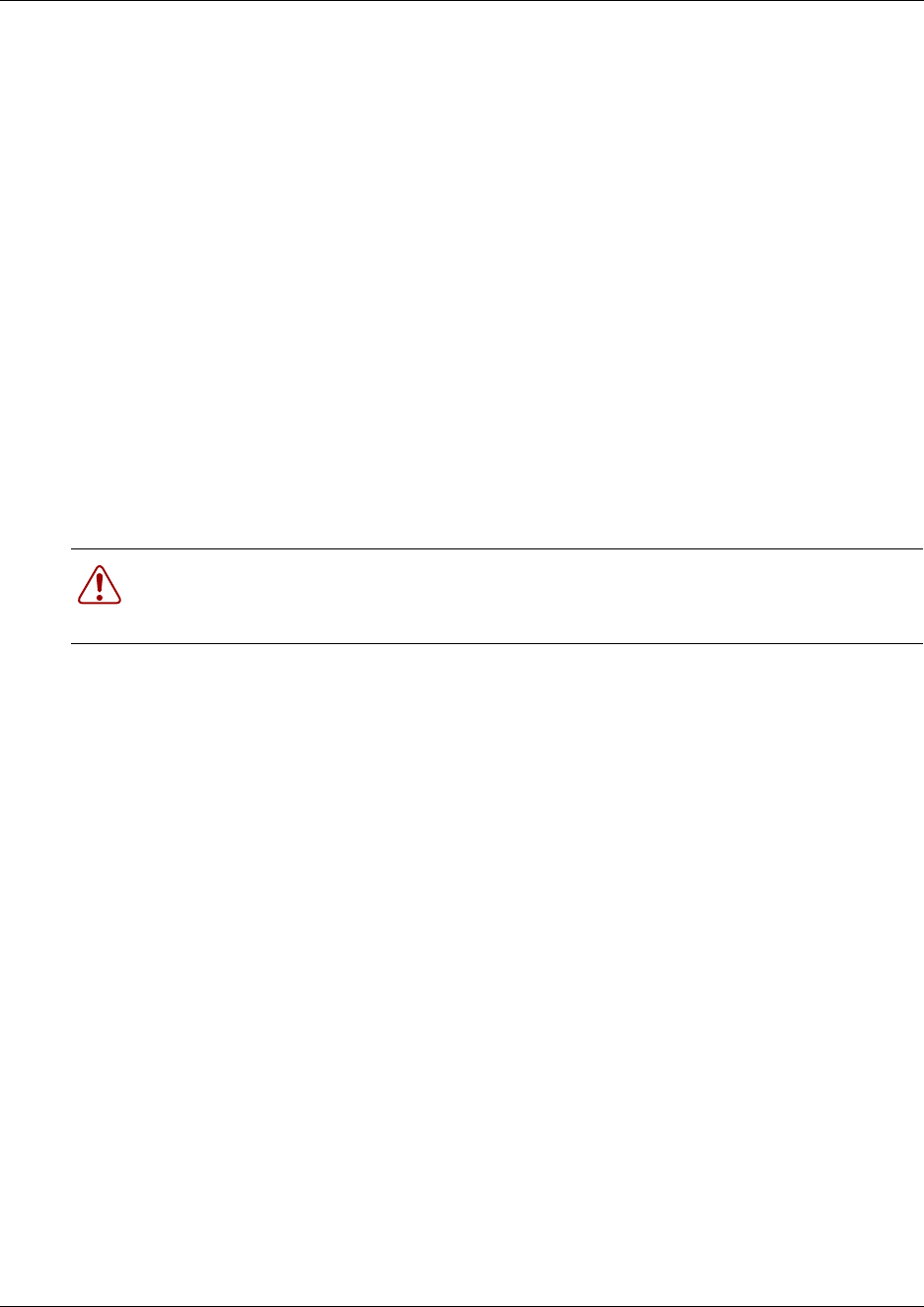
Chapter 8 Install or Replace a Cooling Fan 185
Installation and Maintenance Guide
5Restore the Business Communications Manager system to operation. For details, refer to
“Restart the System after Maintenance” on page 147.
The Business Communications Manager system starts up when you connect the AC power
cord. The start-up process takes several minutes to complete.
6Test the direction of the fan exhaust air flow to determine if the fan is correctly installed.
aHold a piece of paper or your hand close to the fan exhaust. A correctly installed fan blows
air away from the platform base chassis. If you are testing two fans, cover one fan at a time
with your hand.
bIf the fan exhaust air flow is incorrect, remove the cooling fan (See “Remove a BCM400
cooling fan” on page 180) and re-install the fan in the correct position (this procedure).
7This procedure is complete.
Remove a BCM200 cooling fan
Use this procedure to remove the cooling fan in a BCM200 platform configuration.
1If you still have access to the Unified Manager, shut down the system using the Shutdown
command. For details refer to “Shut down the system software” on page 145. Otherwise, skip
to step 2.
2Set up the server for maintenance, as described in “Shut down the system hardware” on page
146.
3Disconnect the Business Communications Manager system from the AC power outlet.
4Attach one end of the grounding strap to your wrist and the other end to a grounded metal
surface.
5Remove the top cover from the platform base chassis (see “Remove the platform base chassis
top cover” on page 161).
6Disconnect the I/O card fan cable connection (see Figure 112).
Warning: Protect the hardware components against damage from electro-static
discharge. Always wear a ground wriststrap before you handle components. Always place
the components in static-free container.
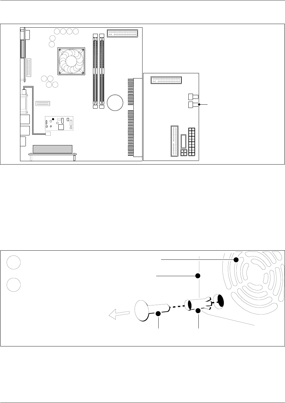
186 Chapter 8 Install or Replace a Cooling Fan
P0993133 03
Figure 112 Disconnect the BCM200 fan cable from the I/O card
7Remove the fan at the rear of the platform base chassis:
aRemove the snap rivets that hold the fan to the platform base chassis. The snap rivet has
two parts; a center pin and a collar. Gently separate the plastic rivet pin with your
fingernails from the center of the rivet collar. Remove the rivet pin and the collar from the
chassis. Place the rivet pin and collar in a safe location.
bPull the fan away from the platform base chassis (from the interior).
cPlace the fan in a safe location.
Figure 113 Remove the snap rivets from the BCM200 platform base chassis
8This procedure is complete.
I/O Card
Main Card
Disconnect from
single fan (fan #1)
Platform base chassis
Rivet pin Rivet collar
Fan exhaust
Remove the rivet collar
from the fan access panel
Remove the rivet pin from
the rivet collar.
2
1
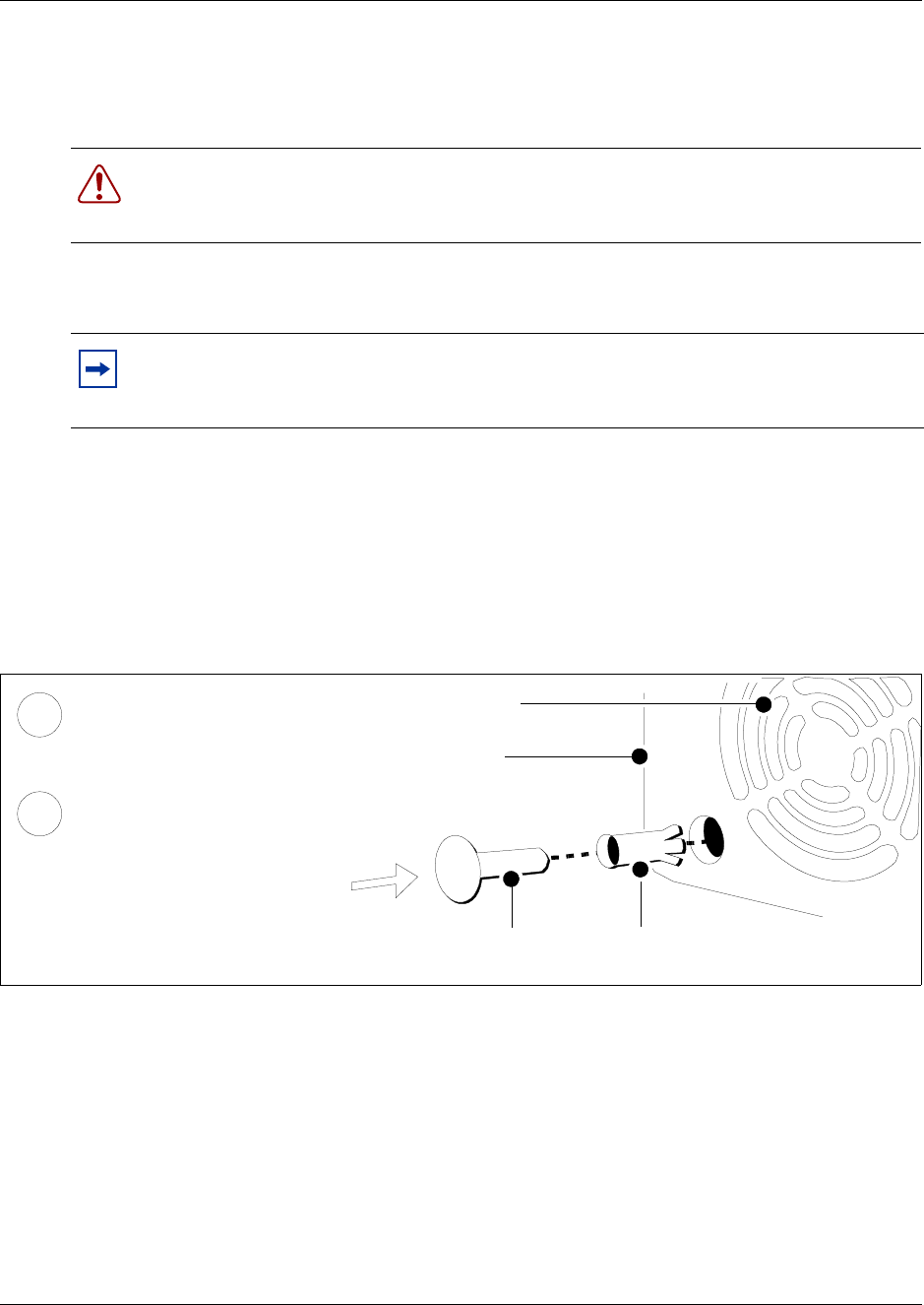
Chapter 8 Install or Replace a Cooling Fan 187
Installation and Maintenance Guide
Install the BCM200 cooling fan
Use this procedure to install a cooling fan in a BCM200 platform base chassis.
1Place the new fan in proper location in the platform base chassis. Ensure the I/O card
connector cable is on the bottom.
2Align the fan chassis mounting holes with the holes on the platform base chassis.
3Attach the fan to the platform base chassis using four snap rivets:
aHold the fan in place and push the rivet collar through the fan access panel and fan chassis
mounting holes.
bInsert the rivet pin into the rivet collar (see Figure 109).
Figure 114 Insert the snap rivets into the BCM200 platform base chassis
4Connect the power supply cable to the I/O card. Connect the Fan to connector #1 on the I/O
card.
5Replace the platform base chassis top cover. See “Install the platform base chassis top cover”
on page 163.
6Restore the Business Communications Manager system to operation. For details, refer to
“Restart the System after Maintenance” on page 147.
The Business Communications Manager system starts up when you connect the AC power
cord. The start-up process takes several minutes to complete.
7Test the direction of the fan exhaust air flow to determine if the fan is correctly installed.
Warning: Protect the hardware components against damage from electro-static
discharge. Always wear a ground wriststrap before you handle components. Always place
the components in static-free container.
Note: Ensure the label of the new fan faces the back wall of the Business
Communications Manager platform base chassis. Airflow is out of the chassis as indicated
by the arrows imprinted on the fan..
Platform base chassis
Rivet pin Rivet collar
Fan exhaust
Insert the rivet collar into
the fan access panel hole.
Insert the rivet pin into the
rivet collar.
1
2
188 Chapter 8 Install or Replace a Cooling Fan
P0993133 03
aHold a piece of paper or your hand close to the fan exhaust. A correctly installed fan blows
air away from the platform base chassis.
bIf the fan exhaust air flow is incorrect, remove the cooling fan (See “Remove a BCM200
cooling fan” on page 185) and re-install the fan in the correct orientation (this procedure).
8This procedure is complete.
Remove an expansion unit fan
Use this procedure to remove a malfunctioning fan from the expansion unit:
The Business Communications Manager expansion unit comes either with one fan or a redundant
fan set. The single-fan unit is not upgradeable.
1Shut down the system following the directions in “Shut down the system software” on page
145.
2Disconnect the fan power cable from the hub card.
3Locate the screws that fasten the fan casing to the expansion unit back wall and remove them.
Refer to Figure 115.
4Remove the four screws (or snap rivets) that hold the fan to the expansion unit.
5Lift the failed fan out of the expansion unit.
Warning: Protect the hardware components against damage from electro-static
discharge. Always wear a ground wriststrap before you handle components. Always place
the components in static-free container.
Note: If the unit has redundant fans, each fan has a connector on the hub board.
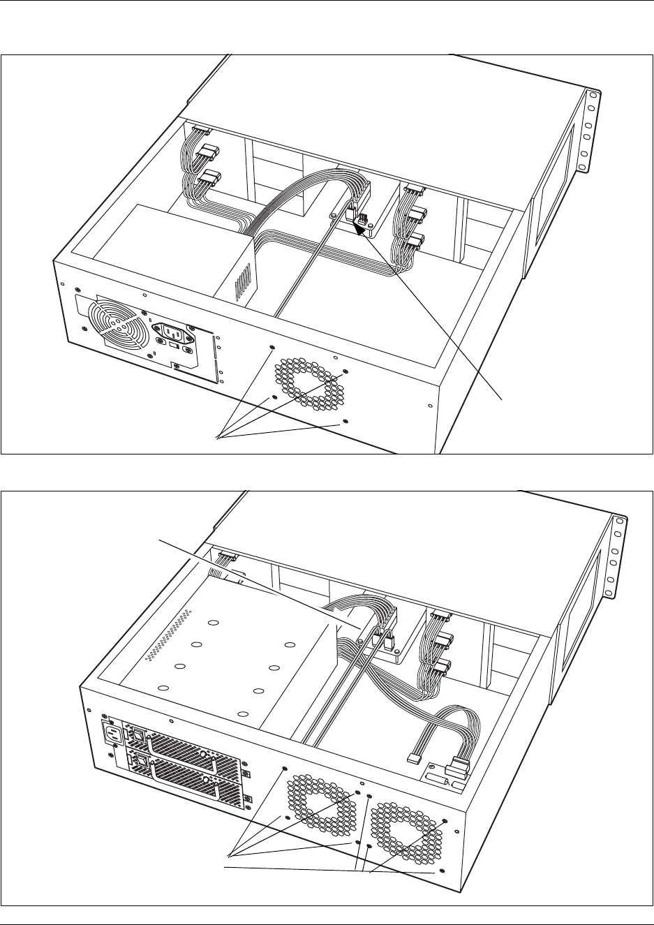
Chapter 8 Install or Replace a Cooling Fan 189
Installation and Maintenance Guide
Figure 115 Fan screws location in expansion unit, 2.0 models.
Figure 116 Fan screws location in expansion unit, 2.5 redundancy models.
FAN
Power supply Fan connector
on hub board
Screws attached to fan
Load resistor
module
Screws attached to fan
Fan connectors
on hub board

190 Chapter 8 Install or Replace a Cooling Fan
P0993133 03
Install an expansion unit fan
Use this procedure to install the fan in the Business Communications Manager expansion unit.
1Place the fan in the expansion unit so that the label faces the back wall of the unit.
2Align the screw holes in the fan with the screw holes in the expansion unit and attach the fan.
3Connect the fan power supply cable to the hub board.
4Replace the cover.
5Restore the Business Communications Manager system to operation. For details, refer to
“Restart the System after Maintenance” on page 147.
The Business Communications Manager system starts up when you connect the AC power
cord. The start-up process takes several minutes to complete.
6Test the direction of the fan exhaust air flow to determine if the fan is correctly installed.
aHold a piece of paper or your hand close to the fan exhaust. A correctly installed fan blows
air away from the platform base chassis.
bIf the fan exhaust air flow is incorrect, remove the cooling fan (See “Remove a BCM200
cooling fan” on page 185) and re-install the fan in the correct orientation (this procedure).
7This procedure is complete.
Warning: Protect the hardware components against damage from electro-static
discharge. Always wear a ground wriststrap before you handle components. Always place
the components in static-free container.
Note: Ensure the label of the new fan faces the back wall of the Business
Communications Manager expansion unit chassis. Airflow is out of the chassis as
indicated by the arrows imprinted on the fan.
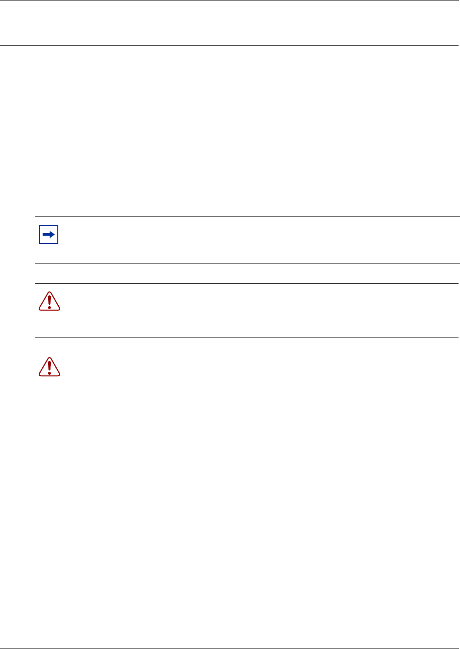
191
Installation and Maintenance Guide
Chapter 9
Replace or Upgrade a Power Supply
The BCM200 uses a standard power supply. The BCM400 and expansion units use either a
standard or redundant power supply.
This chapter describes the following power supply installation and replacement techniques:
• replace a standard power supply
• upgrade from a standard power supply to a redundant power supply (BCM400 only)
• install or replace the power supply modules in a redundant power supply system
• cable routing and mangement
• how to maintain the power supply
Note: For the BCM400 RFO configuration only, a redundant power supply is included.
Use a redundant fan with the redundant power supply (see “Install a BCM400 cooling fan”
on page 182).
Warning: You must remove all of the connections to the Business Communications
Manager before you power the system down.
Failure to disconnect lines before power down can cause damage to the system.
Warning: Protect the hardware components against damage from electrostatic discharge.
Always wear a ground wrist strap before you handle components. Always place the
components in static-free container.
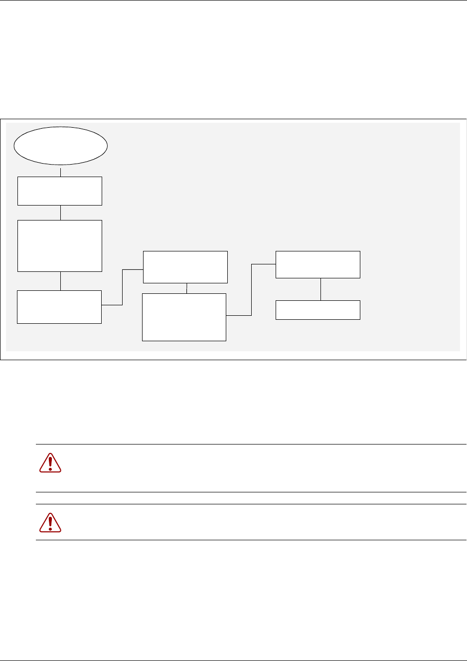
192 Chapter 9 Replace or Upgrade a Power Supply
P0993133 03
Replace a Standard Power Supply
If the platform base chassis or expansion unit has a standard power supply that fails, then all
activity on the system ceases. This procedure describes how to replace a failed standard power
supply unit. Figure 117 provides an overview of the process to replace a standard power supply.
Figure 117 Standard power supply replacement overview
Remove a BCM200 standard power supply
If the standard power supply fails, the system is down. Use this procedure to remove the standard
power supply from a BCM200 platform base chassis.
1Set up the Business Communications Manager for maintenance (see “Shut down the system
hardware” on page 146).
2Disconnect all cables from the front of the base function tray. Disconnect the platform base
chassis and the expansion unit (if applicable), from the AC power connection.
3Remove the top cover from the platform base chassis (see “Remove the platform base chassis
top cover” on page 161).
Warning: Protect the hardware components against damage from electrostatic discharge.
Always wear a ground wrist strap before you handle components. Always place the
components in static-free container.
Warning: Power supply cable management is critical. Cable damage can result due to
loose or incorrectly positioned cables.
System down
Set up unit for
maintenance
Remove failed
power supply
Restore unit to
operation
Check power LED
Reconnect power
supply cables
Check
connections
Install new power
supply
Disconnect
power supply
cables. Note
cable routing
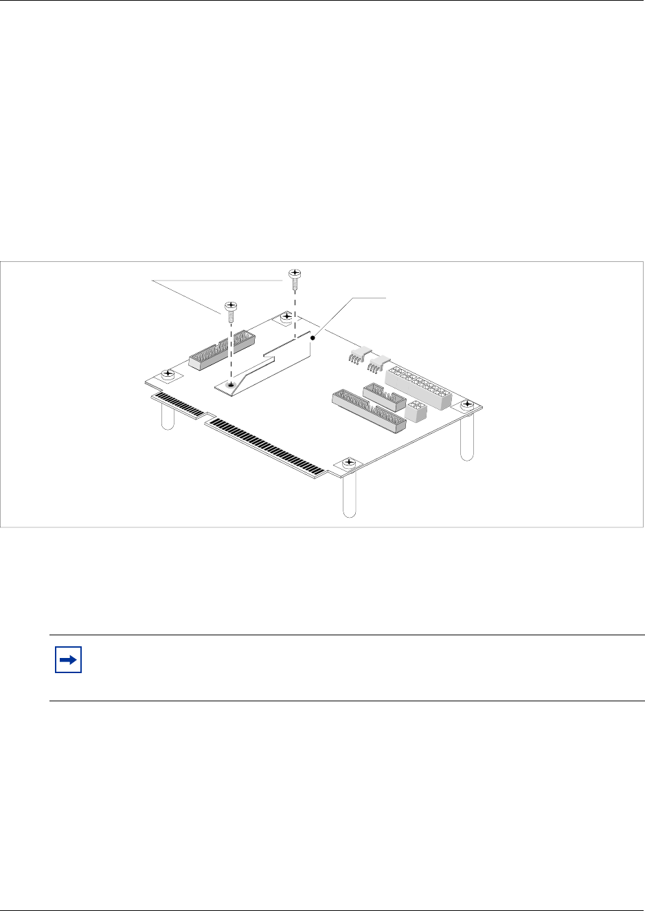
Chapter 9 Replace or Upgrade a Power Supply 193
Installation and Maintenance Guide
4Attach one end of the grounding strap to your wrist and the other end to a grounded metal
surface.
5Locate and disconnect the power supply cables from the I/O card, media bay backplane, and
hard disk.
6Disconnect all cables from the I/O card.
7Partially remove the base function tray (see “Remove the base function tray” on page 150).
Continue to the next step in this procedure when complete.
8Remove the screws that secure the MSC guide bracket to the I/O card. Place the MSC guide
bracket and screws in a safe location (see Figure 118).
Figure 118 Remove the BCM200 MSC guide bracket
9Remove the screws that secure the I/O card to the platform base chassis (see Figure 119).
Place the screws in a safe location.
10 Remove the I/O card from the platform base chassis. Place the I/O card in a safe, clean and
static-free location.
Note: Power supply and hard disk cables run underneath the I/O card. Remember the
location and position of the power supply and hard disk cables. You will need to route the
cables in the same manner when you re-install the power supply.
Unfasten BCM200
MSC guide bracket
mounting screws BCM200 MSC guide bracket
I/O Card
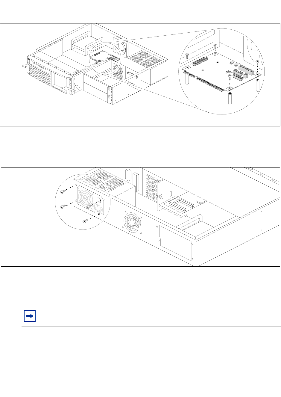
194 Chapter 9 Replace or Upgrade a Power Supply
P0993133 03
Figure 119 Remove the I/O card from the BCM200 platform base chassis
11 Remove the four power supply chassis screws from the back of the platform base chassis (see
Figure 120). Place the screws in a safe location.
Figure 120 Remove the BCM200 power supply chassis screws
12 Separate the power supply cable from the hard disk cable. Cut the tie-wrap that secures the
power supply cable to the hard disk cable (see Figure 122).
13 Remove the power supply from the interior of the platform base chassis.
14 This procedure is complete.
Note: Remove the power supply carefully. Ensure the power supply cables are not
entangled or connected to any internal components.
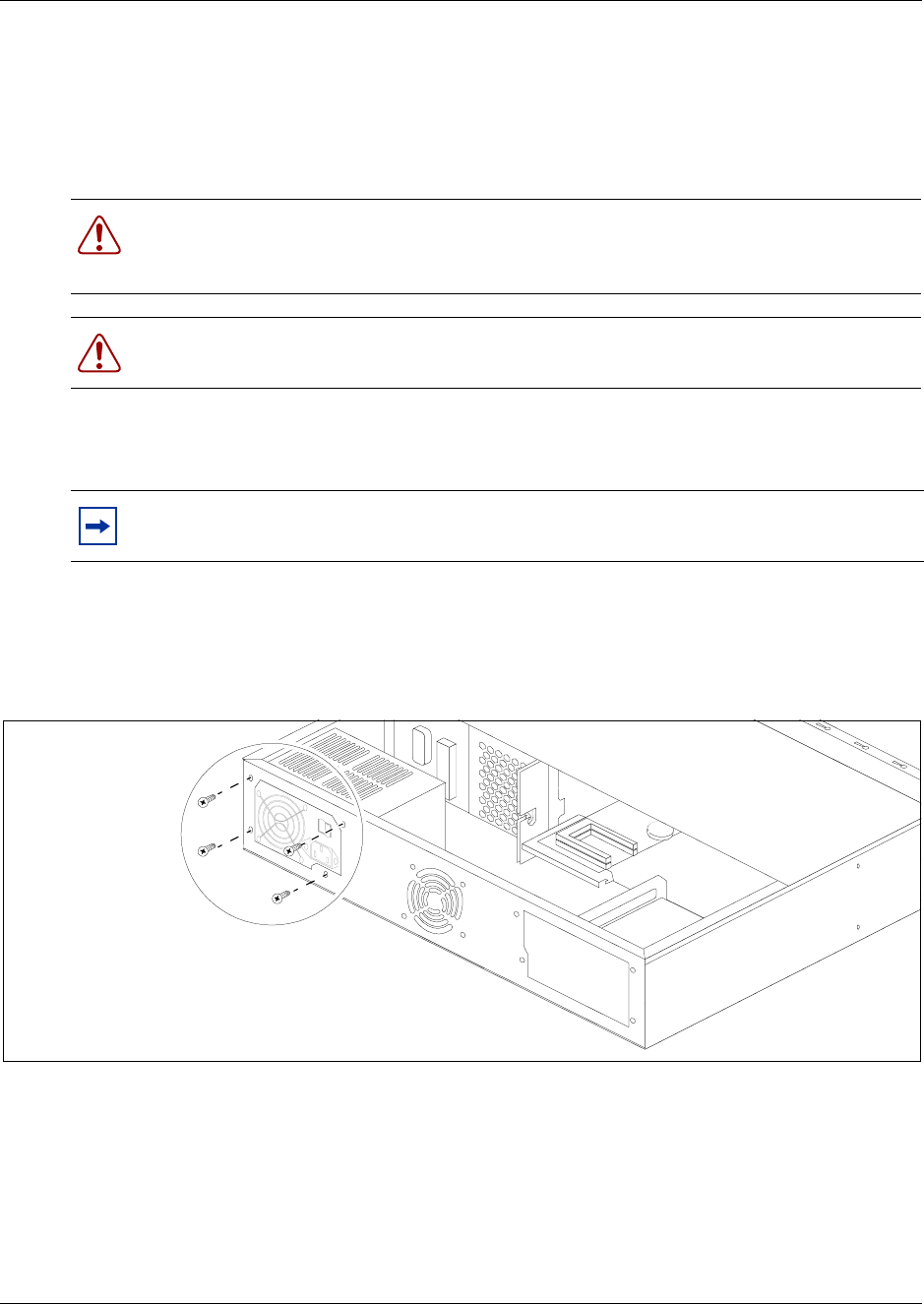
Chapter 9 Replace or Upgrade a Power Supply 195
Installation and Maintenance Guide
Install a BCM200 standard power supply
Use this procedure to install a functional standard power supply in a BCM200 platform base
chassis. The I/O card must be removed from the platform base chassis before you perform this
procedure. The base function tray must be partially removed.
1Obtain and use only the power supply recommended by Nortel Networks.
2Place the new power supply into the platform base chassis.
3Secure the power supply to the platform base chassis. Align the power supply mounting holes
with the chassis holes. Install the chassis screws at the rear of the platform base chassis. See
Figure 121. Do not over-tighten the power supply chassis mounting screws.
Figure 121 Install the BCM200 power supply chassis screws
4Run the P4, P5, P6 power supply cable and the IDE cable to the hard disk. The I/O card is not
installed in the platform base chassis for this step.
Perform the following:
aRoute the power cable between the I/O card chassis standoffs in the area shown (see
Figure 122). Run the IDE cable in the same manner.
bTie-wrap the power cable to the hard disk cable. Position the tie-wrap 1/2 inch from the
hard disk cable sheathing.
Warning: Protect the hardware components against damage from electrostatic discharge.
Always wear a ground wrist strap before you handle components. Always place the
components in static-free container.
Warning: Power supply cable management is critical. Cable damage can result due to
loose or incorrectly positioned cables.
Note: Install the power supply carefully. Ensure the power supply cables are not
entangled or crushed against any internal components.
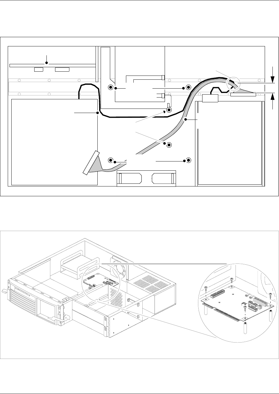
196 Chapter 9 Replace or Upgrade a Power Supply
P0993133 03
cEnsure the remainder of the power cable does not interfere with internal components.
Figure 122 Power and hard disk cable routing
5Install the I/O card. See Figure 123. The I/O card installs on top of the power supply and IDE
cables. Ensure the cables maintain their position as shown in the previous step.
Figure 123 Install the I/O card in the BCM200 platform base chassis
6Install the BCM200 MSC bracket (see Figure 124).
Hard disk
Fan
Power supply
Tie-wrap location P4, P5, P6
+ hard disk cable 1/2” from
hard disk cable sheathing
1/2
”
MSC
IDE (hard
disk) cable
P4, P5, P6 power
cable
Media bay module backplane
I/O card
standoffs
MSC
bracket
standoffs
I/O card
standoffs
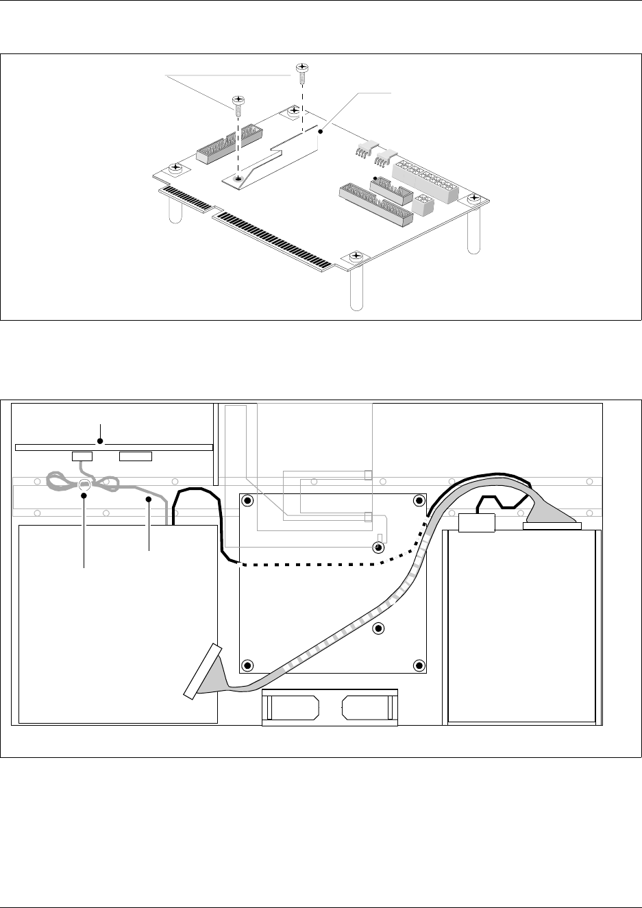
Chapter 9 Replace or Upgrade a Power Supply 197
Installation and Maintenance Guide
Figure 124 Install the BCM200 MSC guide bracket
7Install a P1 power cable to the media bay backplane connector. Tie-wrap the excess cable as
shown in Figure 125.
Figure 125 Tie-wrap excess P1 power cable length
8Connect the hard disk cable to the secondary IDE I/O card connection. Connect the hard disk
cable to the hard disk connector. Connect the power connector to the hard disk (see Figure
125). Insert extra connectors under the hard disk
9Connect the 20 Pin motherboard power cable (P1) and the +12v power Cable (P9) to the I/O
card.
Fasten BCM200
MSC guide bracket
mounting screws BCM200 MSC guide bracket
I/O Card
Hard disk
Fan
MSC
Media bay module backplane
I/O card
Power supply
P1 cable
P1 cable
tie-wrap
198 Chapter 9 Replace or Upgrade a Power Supply
P0993133 03
10 Loop the cables together and tie wrap to the side of the power supply to remove P1, P9, P3,
P7/8 excess cable length. Fold the cables to the rear of the platform base chassis and secure
with a tie-wrap. Ensure the cables are tied far enough back so they do not interfere with the
insertion of the base function tray.
11 Attach the fan plug to the I/O card “Fan #1” connection. Loop excess fan cable length under
the I/O card.
12 Insert the base function tray fully into the platform base chassis. Ensure the base function tray
does not interfer with any cabling.
13 Replace the platform base chassis top cover. See “Install the platform base chassis top cover”
on page 163.
14 Press the power supply switch to the ON position (if applicable). Plug the Business
Communications Manager power cord into an AC power outlet.
15 Restore the Business Communications Manager to operation. For details, refer to “Restart the
System after Maintenance” on page 147. The Business Communications Manager system
starts when you connect the AC power cord. Wait for the start-up process to finish.
16 Monitor the power LED on the base function tray. Refer to Table 24.
aIf the Business Communications Manager does not power-up, press the reset button on the
base function tray front panel.
bIf the Power LED is red, and does not respond to a manual reset, this indicates a faulty
power condition. Contact your Nortel Networks representative.
cIf the Power LED indicates green, the system is operating normally. Continue to the next
step in this procedure.
17 This procedure is complete.
Note: Verify the power supply cables are connected correctly and do not interfere with
any internal components.
Table 24 Power supply LED
LED
Label Description Green
LED On Green
LED Flash Red LED On (Only) Green
LED Off
Indicates state of system power. OK N/A a minimum of 1 PS needs
attention* N/A

Chapter 9 Replace or Upgrade a Power Supply 199
Installation and Maintenance Guide
Remove a BCM400 standard power supply
Use this procedure to remove the standard power supply from a BCM400 platform base chassis.
1Set up the Business Communications Manager for maintenance (see “Shut down the system
hardware” on page 146).
2Disconnect all cables from the front of the base function tray.
3Disconnect the platform base chassis and the expansion unit (if applicable), from the AC
power connection.
4Remove the top cover from the platform base chassis (see “Remove the platform base chassis
top cover” on page 161).
5Attach one end of the grounding strap to your wrist and the other end to a grounded metal
surface.
6Disconnect all cables from the I/O card.
7Locate and disconnect the power supply cables from the media bay backplane and hard disk.
8Partially remove the base function tray (see “Remove the base function tray” on page 150).
Continue to the next step of this procedure when complete.
9Unfasten the power supply cable clamp located on the underside of the platform base chassis
top cover (see Figure 126). Gather the power supply cables away from the interior and toward
the rear of the platform base chassis.
10 Remove the four power supply chassis screws from the back of the platform base chassis (see
Figure 126). Place the screws in a safe location.
Warning: Protect the hardware components against damage from electrostatic discharge.
Always wear a ground wrist strap before you handle components. Always place the
components in static-free container.
Warning: Power supply cable management is critical. Cable damage can result due to
loose or incorrectly positioned cables.
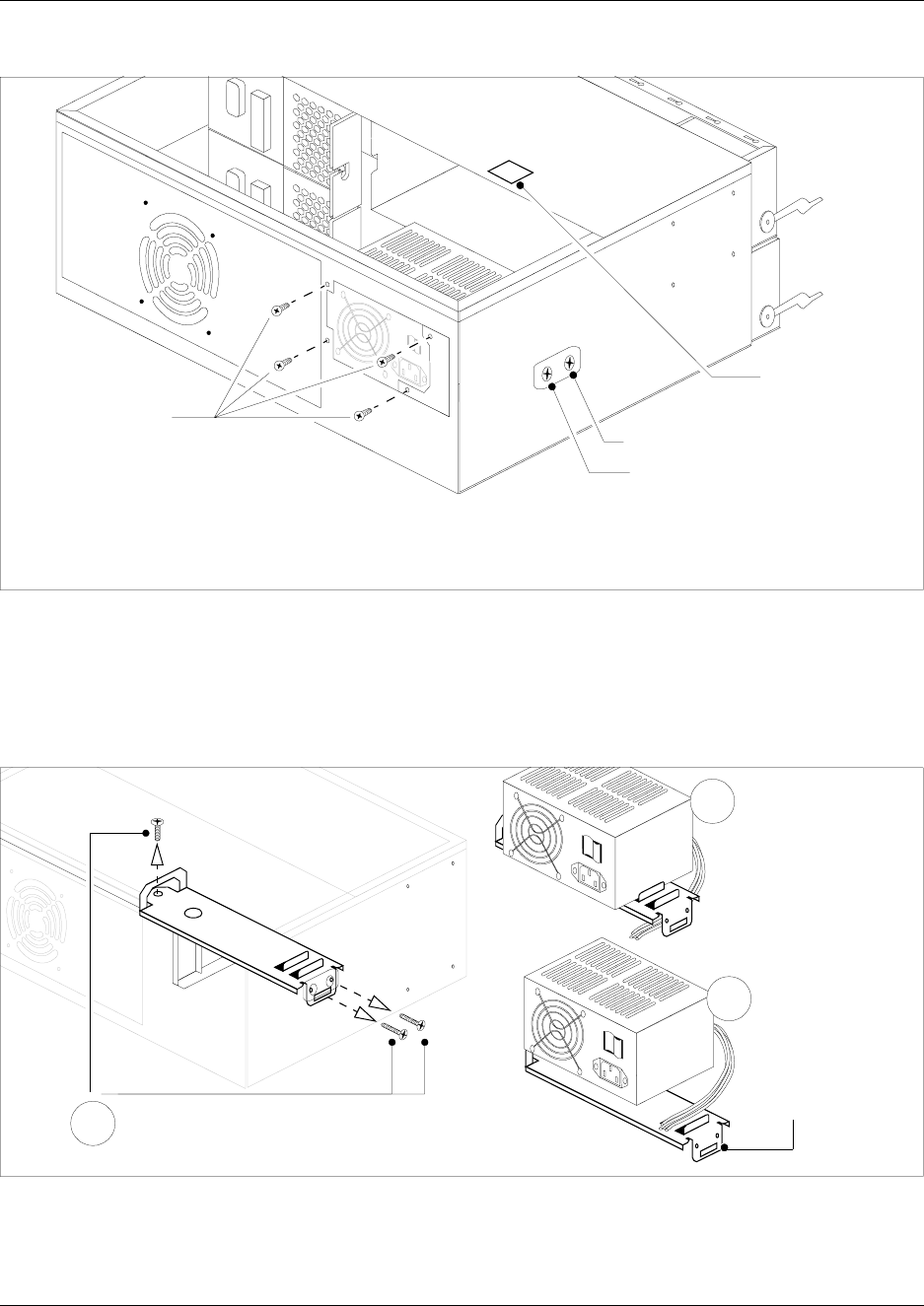
200 Chapter 9 Replace or Upgrade a Power Supply
P0993133 03
Figure 126 Remove the BCM400 power supply chassis screws
11 Unfasten the exterior and interior power supply support bracket mounting screws (see Figure
127). Place the screws in a safe location.
12 Remove the power supply and support bracket out and away from the BCM400 platform base
chassis.
Figure 127 Remove the power supply and support bracket
13 Remove the tie-wrap from the power supply support bracket. Place the power supply in a safe,
static free location.
14 This procedure is complete.
Unfasten cable
clamp - located
on underside of
chassis cover
Unfasten exterior
power suppy support
bracket mounting
screws
Unfasten power
supply chassis
mounting screws
Cut the cable
tie-wrap away from
the power supply
support bracket.
Remove power
supply
Remove the power
supply & support
bracket from platform
base chassis
1
2
3
Remove exterior & interior power suppy support
bracket mounting screws (power supply not shown) -
Remove power supply support bracket
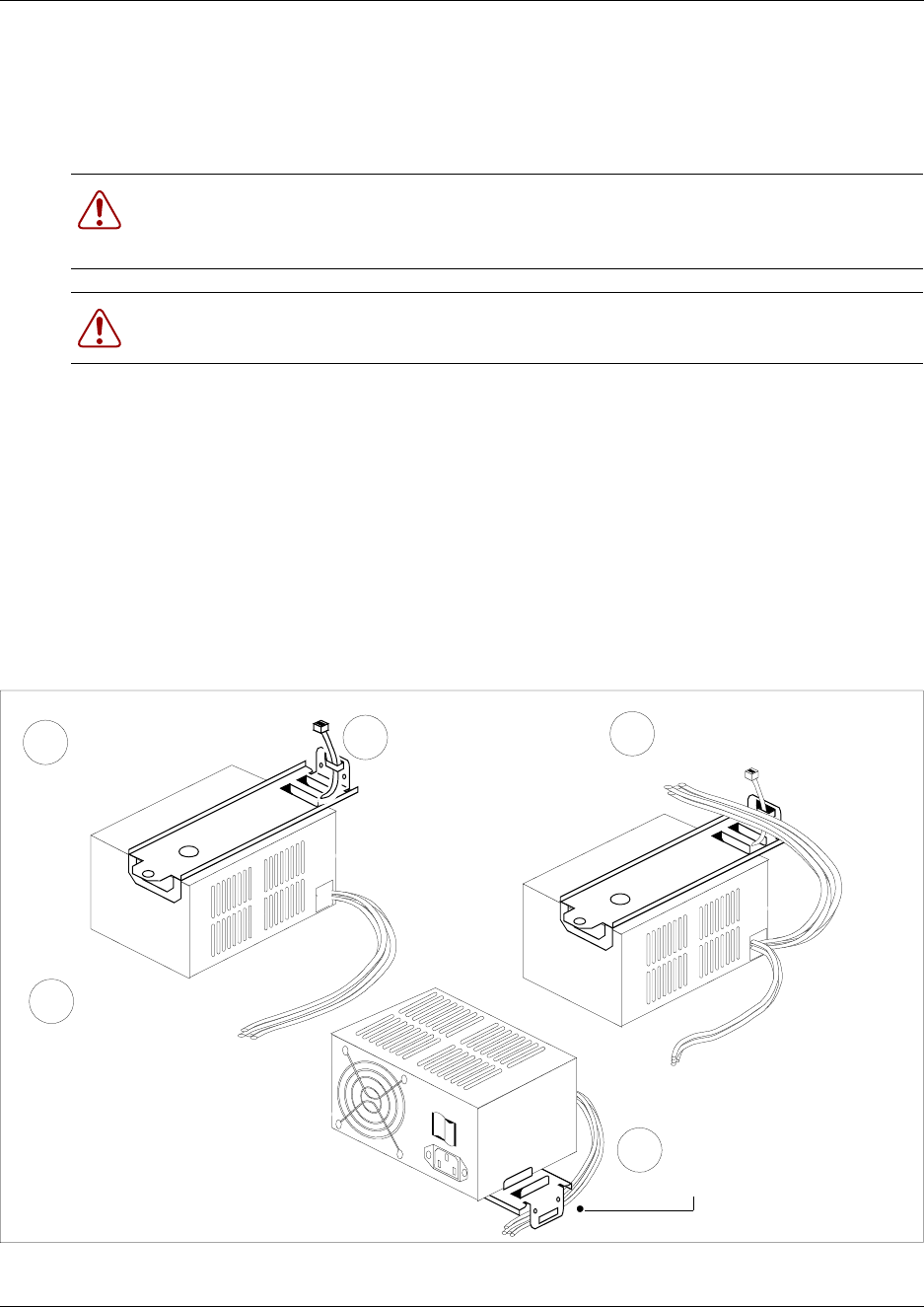
Chapter 9 Replace or Upgrade a Power Supply 201
Installation and Maintenance Guide
Install a BCM400 standard power supply
Use this procedure to install a functional standard power supply in a BCM400 platform base
chassis. The base function and advanced function trays must be partially removed.
1Ensure the new power supply is an auto-adjust power supply.
2Insert a tie-wrap in the power supply support bracket lanclet.
3Place the standard power supply (top down) on a flat surface. Place the power supply support
bracket on the bottom surface of the power supply.
4Gather together and route the main card 20 Pin power cable (P1) and the +12v power cable
(P9) at the tie-wrap.
5Secure the the power cables to the power supply support bracket with the tie-wrap (from step
2) - see Figure 128.
Figure 128 Fasten the power supply support bracket cables
Warning: Protect the hardware components against damage from electrostatic discharge.
Always wear a ground wrist strap before you handle components. Always place the
components in static-free container.
Warning: Power supply cable management is critical. Cable damage can result due to
loose or incorrectly positioned cables.
Insert a tie-wrap
in the power
supply support
bracket lanclet
3Gather and route the power
cables at the tie-wrap
5Secure the power cables to
the power supply bracket with
the tie-wrap
4
Place power supply upside
down on flat surface
1
2Place the support
bracket on the power
supply
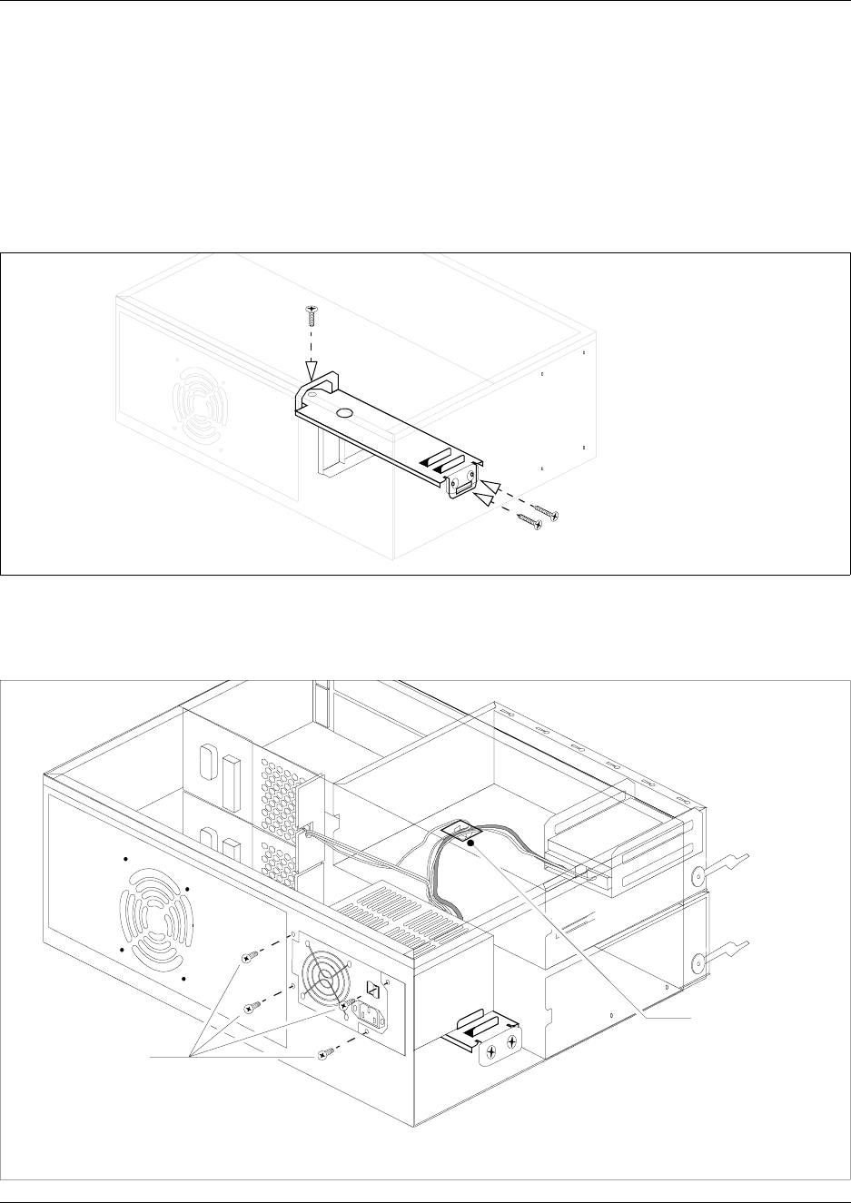
202 Chapter 9 Replace or Upgrade a Power Supply
P0993133 03
6Insert the standard power supply and support bracket in the platform base chassis. The power
supply support bracket rests on the MSC guide bracket on one side, and the chassis wall on the
other.
7Ensure the mounting holes in the power supply support bracket align with the holes in the
platform base chassis.
8Fasten the power supply suppport bracket mounting screws (see Figure 129).
Figure 129 Fasten the power supply support bracket to the platform base chassis
9Align the mounting holes in the power supply with the chassis holes at the rear of the platform
base chassis. Fasten the power supply mounting screws to the platform base chassis.
Figure 130 Fasten the standard power supply to the platform base chassis
fasten the power supply support
bracket (power supply not shown)
Fasten power,
auxilliary, IDE
cables using
cable clamp -
located on
underside of
chassis cover
Fasten power
supply chassis
mounting screws
Chapter 9 Replace or Upgrade a Power Supply 203
Installation and Maintenance Guide
10 Attach the 20 pin motherboard connector and the +12V power connector into the I/O card.
11 Route the power cable, auxilliary and IDE cable to the hard disk cage. Bundle the cables
together and fasten to the roof of the platform base chassis using the cable clamp (see Figure
130).
12 Connect the power cable and IDE cable to the hard disk.
13 Run the auxilliary cable to the chassis cable slot (see next step).
14 Connect cable runs P2 and P3 to the media bay backplane as follows.
aConnect cable P2 into the bottom media bay module backplane power connector
bConnect cable P3 into the top media bay module backplane connector.
cBundle power cables P2 and P3 along with auxiliary cable (P7/8) together with a grommet
(see Figure 138).
dInsert the P2, P3 and auxiliary cables into the cable slot on the chassis (secured with the
grommet).
15 This procedure is complete.
Upgrade to a redundant power supply
Use the procedures in this section to upgrade a BCM400 platform base chassis, currently equipped
with a standard power supply, with a redundant power supply. Figure 131 provides an overview of
the steps required to upgrade your Business Communications Manager (BCM400) system from a
standard power supply to a redundant power supply.
Note: A Business Communications Manager expansion unit with a standard power
supply cannot be upgraded. You must replace the expansion unit chassis.
Note: When you install a redundant power supply, you must also install a redundant
cooling fan included with the redundancy upgrade kit.
Note: When you install a redundant power supply, you must also remove the jumper
installed in the PSU Status connector (RPS output signaling connector) on the I/O card.
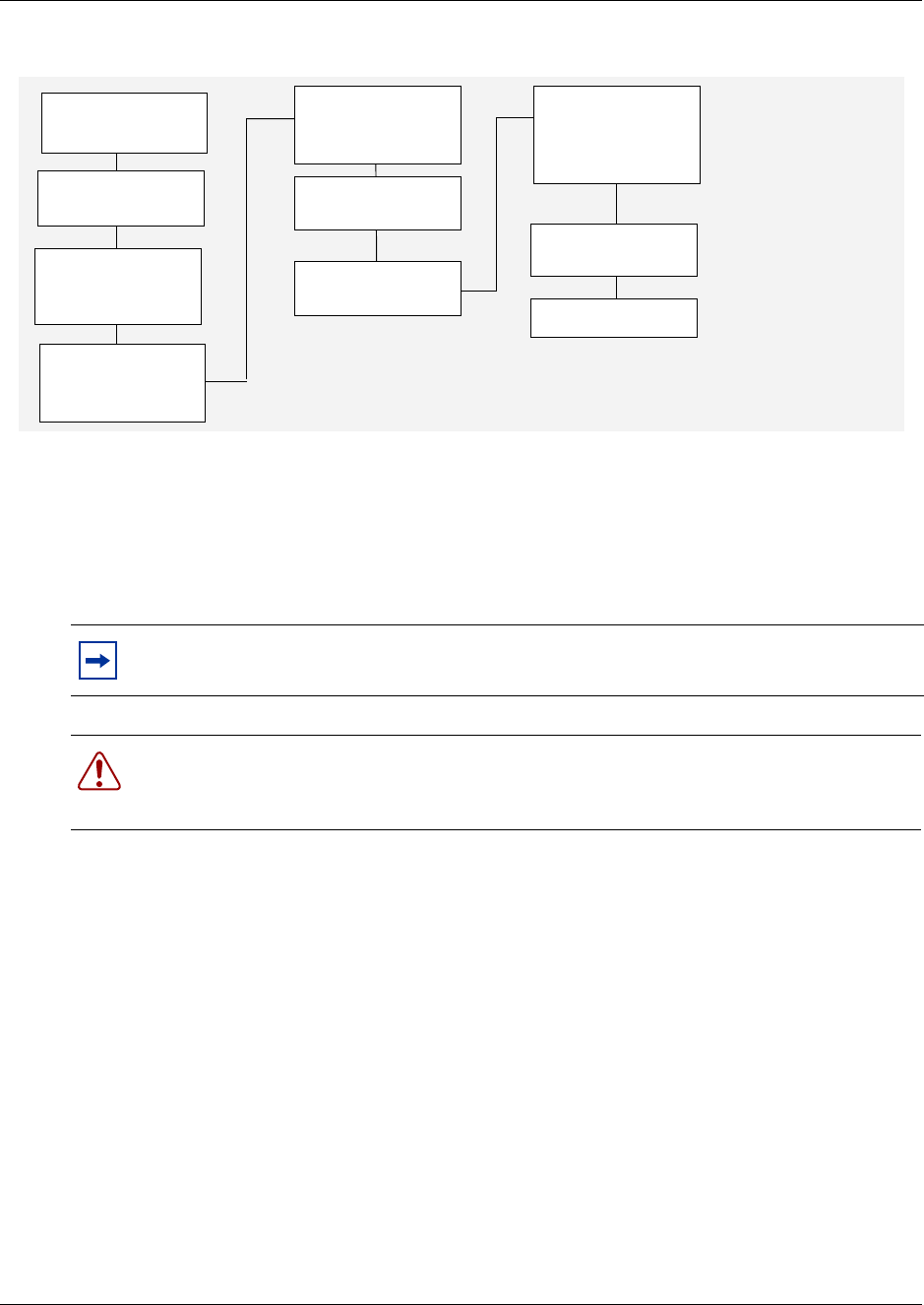
204 Chapter 9 Replace or Upgrade a Power Supply
P0993133 03
Figure 131 Redundant power supply upgrade overview
Remove the PSU status connector jumper
Use this procedure if you are installing a redundant power supply for the first time. Use this
procedure only with the BCM400 platform base chassis.
1If you still have access to the Unified Manager, shut down the system using the Shutdown
command. For details, refer to “Shut down the system software” on page 145. Otherwise, skip
to step 2.
2Set up the Business Communications Manager for maintenance, as described in “Shut down
the system hardware” on page 146.
3Disconnect the BCM400 system from the AC power outlet.
4Remove the platform base chassis top cover. Refer to “Remove the platform base chassis top
cover” on page 161. Continue to the next step in this procedure when complete.
5Locate the PSU Status connector on the I/O card (see Figure 132).
6Remove the RPS output signaling connector jumper. Use needle-nose pliers to pull the jumper
out and away from the connector. Place the jumper in a safe location.
7Connect the PA cable to the PSU status connector (see Figure 31).
Note: When you upgrade to a redundant power supply, you should also install a redundant
fan. Refer to “Install a BCM400 cooling fan” on page 182.
Warning: Protect the hardware components against damage from electrostatic discharge.
Always wear a ground wrist strap before you handle components. Always place the
components in static-free container.
Shut the system
down
Install redundant
power supply
cage
Remove PSU
jumper
Insert both
modules into
power supply
cage
Restore unit to
operation
Check power LED
Note cable
routing. Remove
cables
Remove the
standard power
supply
Make internal
connections
Set up unit for
maintenance
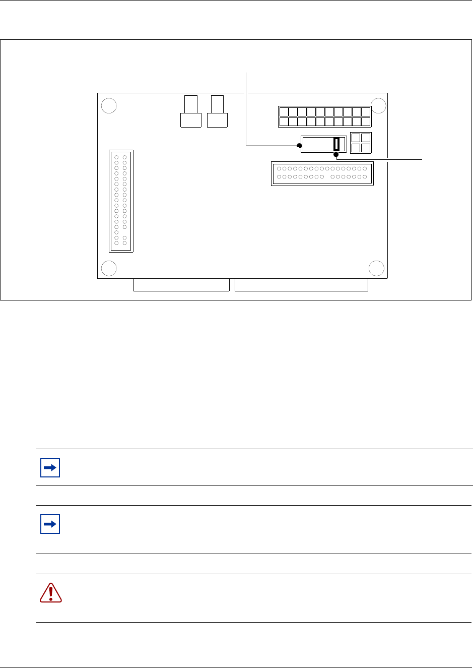
Chapter 9 Replace or Upgrade a Power Supply 205
Installation and Maintenance Guide
Figure 132 Remove the PSU status connector jumper
8This procedure is complete.
Install a redundant power supply cage
This procedure describes how to install a redundant power supply cage in the BCM400 platform
base chassis. After you install the redundant power supply cage in the platform base chassis, install
the two power supply modules (see “Install a power supply module” on page 212).
Use this procedure only with the BCM400 platform base chassis.
Note: When you upgrade to a redundant power supply, you should also install a redundant
fan. Refer to “Install a BCM400 cooling fan” on page 182.
Note: When you install a redundant power supply, you must also remove the jumper
installed in the PSU Status connector (RPS output signaling connector) on the I/O card.
See Remove the PSU status connector jumper on page 204.
Warning: Protect the hardware components against damage from electrostatic discharge.
Always wear a ground wrist strap before you handle components. Always place the
components in static-free container.
I/O Card
PSU Status
connector
Jumper
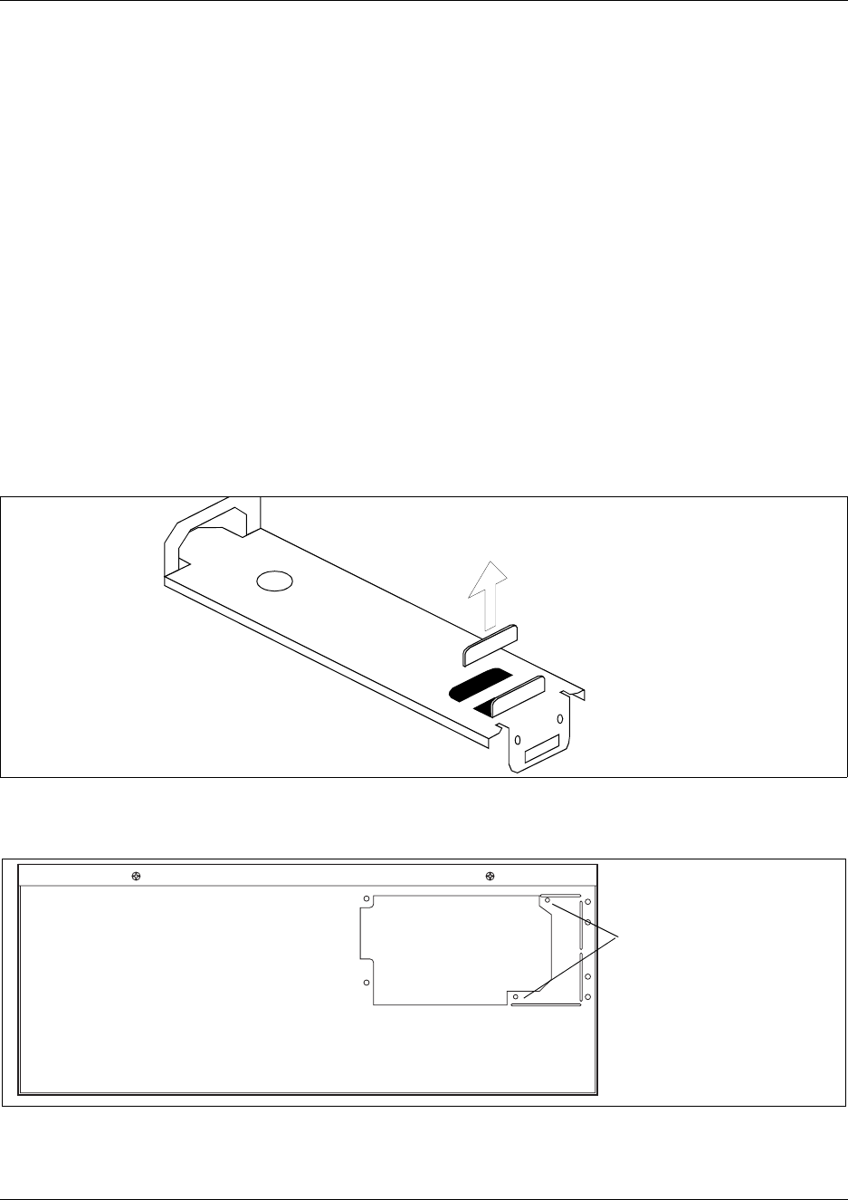
206 Chapter 9 Replace or Upgrade a Power Supply
P0993133 03
1If you still have access to the Unified Manager, shut down the system using the Shutdown
command. For details, refer to “Shut down the system software” on page 145. Otherwise, skip
to step 2.
2Set up the Business Communications Manager for maintenance, as described in “Shut down
the system hardware” on page 146.
3Disconnect the BCM400 system from the AC power outlet.
4Remove the standard power supply from the platform base chassis (see Remove a BCM400
standard power supply on page 199). Continue to the next step in this procedure when
complete.
5Remove the power supply support bracket from the platform base chassis (see Remove a
BCM400 standard power supply on page 199). Continue to the next step in this procedure
when complete.
6Remove the power supply adapter tab from the support bracket (see Figure 133). Use pliers to
bend and snap the tab away from the support bracket. Make sure you remove only the inner
adapter tab.
Figure 133 Remove the BCM400 power supply adapter tab from the support bracket
7Remove the knockout plate from the rear of the platform base chassis (see Figure 134).
Figure 134 Remove the power supply knockout bracket
Remove the
inner adapter tab
Remove this bracket to
accommodate redundant
power supply
Rear view
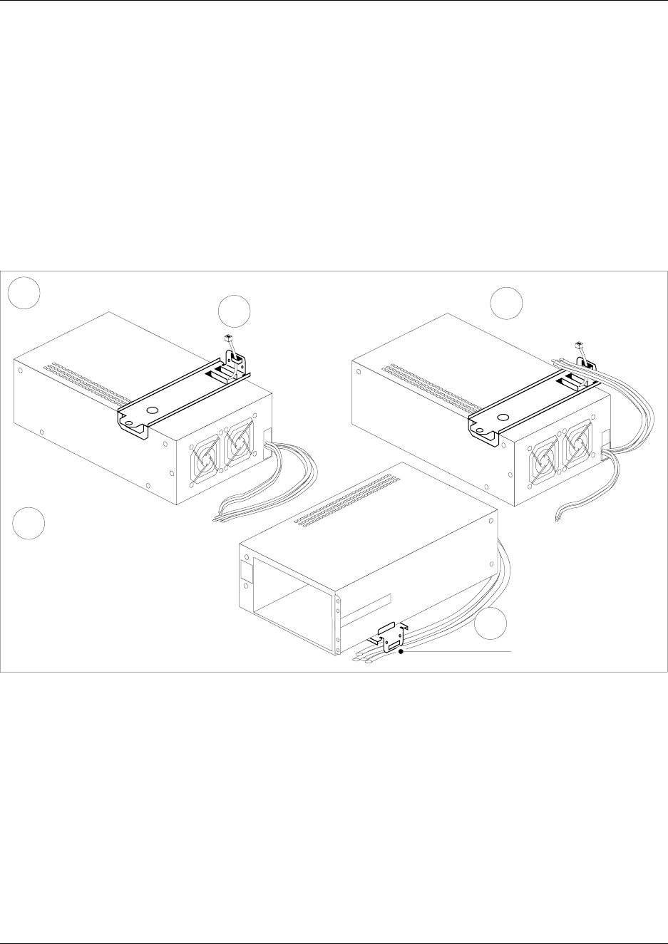
Chapter 9 Replace or Upgrade a Power Supply 207
Installation and Maintenance Guide
8Remove both power supply modules from the redundant power supply cage before you install
the power supply in the platform base chassis (see Remove a power supply module on page
214). Continue to the next step of this procedure when complete.
9Place the redundant power supply (top down) on a flat surface. Place the power supply support
bracket on the bottom surface of the power supply.
10 Insert a tie-wrap in the power supply support bracket lanclet.
11 Gather together and route the Motherboard 20 Pin power cable (P1) the +12v power cable
(P9), the 3.3v load cable (PB), and the PS monitor Cable (PA) to the tie-wrap.
12 Secure the the cables to the power supply support bracket with a tie-wrap (see Figure 128).
Figure 135 Fasten the power supply support bracket cables
13 Install the power supply support bracket in the BCM400 platform base chassis (see Figure
129).
14 Position the redundant power supply cage in the base platform chassis. Make sure the power
supply module tray opening faces the rear of the platform base chassis.
15 Align the mounting holes in the redundant power supply cage with the screw holes in the
platform base chassis.
16 Attach the redundant power supply cage to the platform base chassis using the four chassis
mounting screws. Refer to Figure 136.
5Secure the cables to the
power supply bracket
with the tie-wrap
Insert a tie-wrap in
the power supply
support bracket
lanclet
3
Gather and route the
cables to the
tie-wrap
4
Place power supply top side
down on flat surface
1
2Place the support
bracket on the power
supply
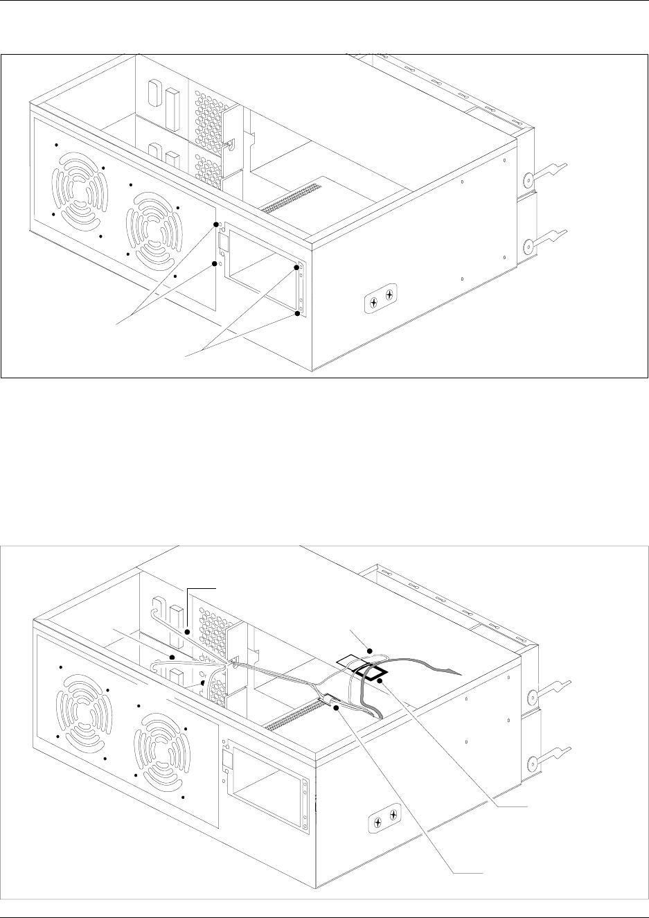
208 Chapter 9 Replace or Upgrade a Power Supply
P0993133 03
Figure 136 Attach the redundant power supply cage
17 If you have not already done so, install a redundant fan into the unit. Refer to “Install a
BCM400 cooling fan” on page 182. Continue to the next step of this procedure when
complete.
18 Install a new cable clamp on the underside of the top cover. Place the new cable clamp beside
the existing cable clamp. Use the cable clamp to secure the power, IDE and auxilliary cables to
the roof of the platform base chassis.
Figure 137 Install a new cable clamp
Fasten power supply
chassis mounting
screws
Mount new cable
clamp - located
on underside of
chassis cover
P2
P3
Auxilliary
Auxilliary
Cable clamp - located
on top of power supply
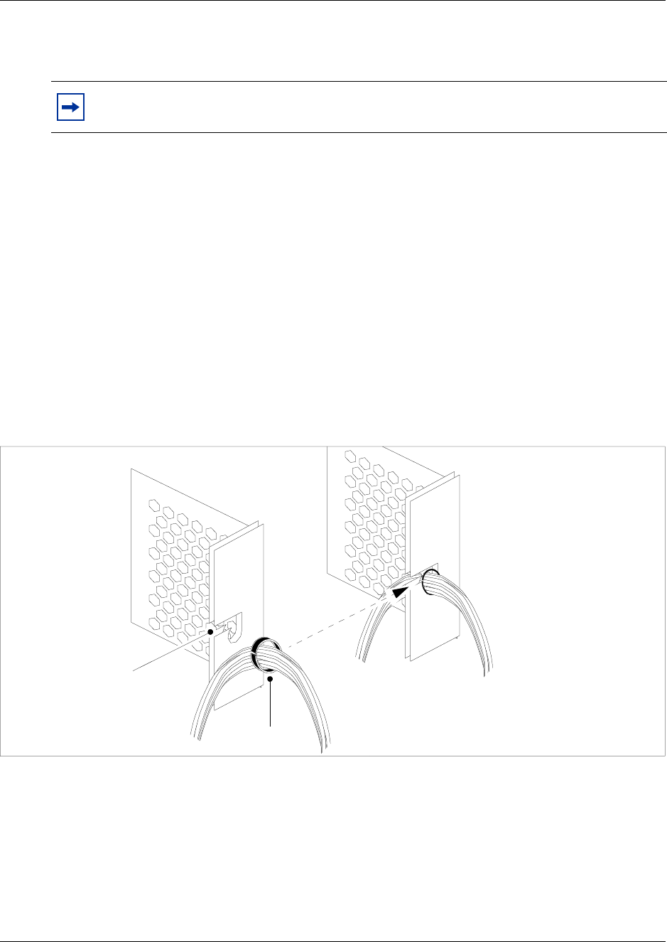
Chapter 9 Replace or Upgrade a Power Supply 209
Installation and Maintenance Guide
19 Run the power supply, auxilliary and IDE cables to the hard disk. Secure these cables in the
new cable clamp.
20 Connect cable runs P2 and P3 to the media bay backplane (see Figure 137) as follows:
aBundle the cables together. Run the cables on the top of the power supply chassis and
secure with the cable clamp.
bConnect cable P2 into the bottom media bay module backplane power connector
cConnect cable P3 into the top media bay module backplane connector.
dBundle power cables P2 and P3 along with auxiliary cable (P7/8) together with a grommet
(see Figure 138).
eInsert the P2, P3 and auxiliary cables into the cable slot on the chassis (secured with the
grommet).
fEnsure that one power run connects to one MBM backplane connector. Do not connect a
single power run to both MBM backplane connectors.
Figure 138 Install a cable grommet
21 Install the platform base chassis top cover. See “Install the platform base chassis top cover” on
page 163.
22 This procedure is complete.
Note: Verify the power supply cables are connected correctly, completely and are routed
so they do not interfere with any internal components when moved.
Cable grommet
Insert the P2, P3
and auxiliary
cables into the
cable slot
Cable slot

210 Chapter 9 Replace or Upgrade a Power Supply
P0993133 03
Remove a BCM400 redundant power supply cage
Use this procedure to remove an existing redundant power supply cage from the BCM400
platform base chassis.
1Set up the server for maintenance (see “Shut down the system hardware” on page 146).
Disconnect all cables from the front of the base function tray.
2Disconnect the platform base chassis and the expansion unit (if applicable), from the AC
power connection.
3Remove the top cover from the BCM400 platform base chassis (see “Remove the platform
base chassis top cover” on page 161).
4Attach one end of the grounding strap to your wrist and the other end to a grounded metal
surface.
5Remove the power supply modules (see Remove a power supply module on page 214).
Continue to the next step in this procedure when complete.
Note: Partially remove the power supply module from the power supply cage. Do not
completely remove the power supply module. IMPORTANT: When the power is on, wait
several seconds before removing the power supply module completely from the power supply
cage to ensure complete electrical discharge.
6Disconnect the power supply cables from the I/O card, media bay backplane, and hard disk.
7Unfasten the cable clamp that holds the power and IDE cables in place. The cable clamp is
located under the top cover of the platform base chassis.
8Run all cables to the rear, exterior of the platform base chassis.
9Remove the four power supply chassis screws from the rear of the platform base chassis (see
Figure 139). Place the screws in a safe location.
Warning: Protect the hardware components against damage from electrostatic discharge.
Always wear a ground wrist strap before you handle components. Always place the
components in static-free container.
Warning: Risk of shock.
Hazardous voltage levels are maintained for several seconds on removable modules. Do
not completely remove the module from the power supply cage for several seconds after
disengaging the module from the cage.
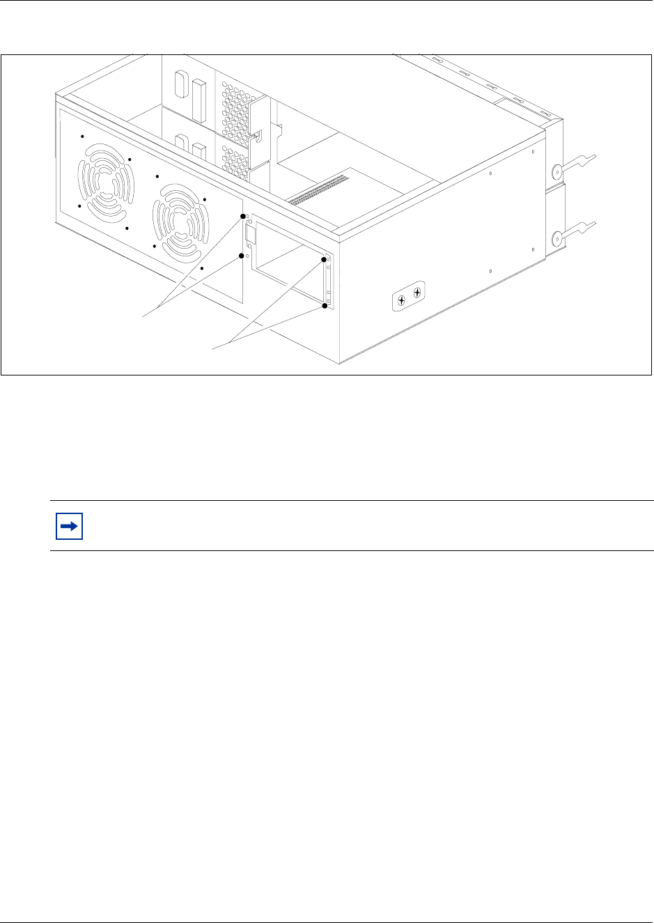
Chapter 9 Replace or Upgrade a Power Supply 211
Installation and Maintenance Guide
Figure 139 Remove the BCM400 redundant power supply chassis screws
10 Unfasten the exterior and interior power supply support bracket mounting screws (see Figure
127). Place the screws in a safe location.
11 Remove the redundant power supply cage and support bracket out and away from the
BCM400 platform base chassis (see Figure 140). Place the power supply in a safe, clean and
static-free location.
12 Cut the cable ties that hold the power cables to the power supply support bracket. Be careful
not to cut or damage the cable insulation.
Note: Remove the power supply carefully. Ensure the power supply cables are not
entangled or connected to any internal components.
Remove power supply
chassis mounting
screws
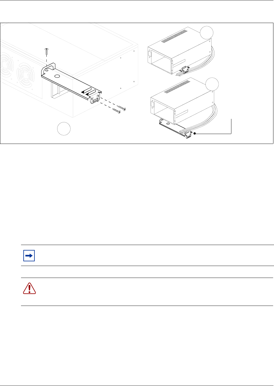
212 Chapter 9 Replace or Upgrade a Power Supply
P0993133 03
Figure 140 Remove the redundant power supply cage and support bracket
13 This procedure is complete.
Install a power supply module
This procedure describes how to install power supply modules in the power supply cage. After you
install the redundant power supply cage in the platform base chassis, insert the two power supply
modules.
Use this procedure also to replace faulty power supply modules. Redundant power supply modules
can be exchanged while the system is running, as long as one of the modules remains active. This
section is relevant only with the BCM400 platform base chassis..
1Ensure you have the correct redundant power supply cage installed in the BCM400 platform
base chassis (see Install a redundant power supply cage on page 205).
2Ensure that you position the power supply modules correctly before inserting them into the
power supply cage. The green LEDs are located at the top right of the power supply modules.
3Insert the power supply modules into the redundant power supply cage at the rear of the
platform base chassis.
Note: When you upgrade to a redundant power supply, you should also install a redundant
fan. Refer to “Install a BCM400 cooling fan” on page 182.
Warning: Protect the hardware components against damage from electrostatic discharge.
Always wear a ground wrist strap before you handle components. Always place the
components in static-free container.
Cut the cable tie-wrap
away from the power
supply support
bracket. Remove
power supply
Unfasten the power
supply support bracket
(power supply not shown)
Remove the power
supply & support
bracket from platform
base chassis
1
2
3
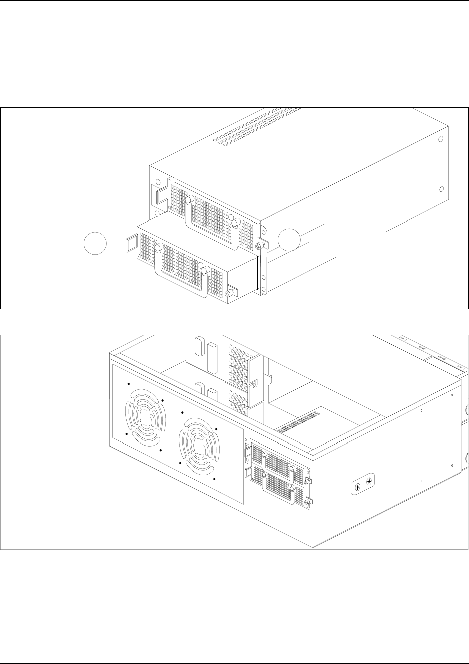
Chapter 9 Replace or Upgrade a Power Supply 213
Installation and Maintenance Guide
aPush on the power supply module until the face of the module is flush with the casing. You
hear a click when the power supply module is properly seated.
bSecure each module with the power supply locking nut (located on the right side of the
module). Refer to Figure 141.
Figure 141 Install the power supply modules into the power supply cage
Figure 142 BCM400 platform redundant power supply (rear view)
4If you are installing the redundant power supply for the first time, restore the Business
Communications Manager to operation as described in “Restart the System after
Maintenance” on page 147.
The Business Communications Manager system starts up when you connect the AC power
cord. If the system does not start and the Red Power LED is on, you may need to press the
reset button on the base function tray panel to start the system.
Power supply modules slide
into the power supply cage.
Push the power supply
module into the power
supply cage.
1Fasten the power supply
module locking nut.
2
Rear view
Power supply
mounted in the
BCM400 redundant
feature option platform
base chassis
214 Chapter 9 Replace or Upgrade a Power Supply
P0993133 03
If you are replacing a faulty power supply module, the Business Communications Manager is
already in operation. The power supply module powers-up when fully and correctly inserted in
the redundant power supply cage.
5Verify the LEDs on the power supply module are lit. Verify all LEDs on the base function tray
indicate the system functions correctly.
6This procedure is complete.
Remove a power supply module
Use this procedure for any of the following conditions:
• Remove a single failed power supply module. A power supply module indicates a failure when
the green LED (located on the module) is not lit.
• Remove power supply modules before you install a new power supply cage in the BCM400
platform base chassis (see “Upgrade to a redundant power supply” on page 203).
1Unfasten the power supply module locking nut. When the nut is fully unfastened, the nut
should move freely in the screw cage.
2Swing the power supply module handle to a 90 degree angle to the power supply module.
3Grasp the power supply module handle. With your thumb, compress the locking tab toward the
handle.
4Pull the power supply module out of the power supply cage (see notes in this step).
Note: If you are replacing a faulty power supply module, power-down the power supply
module. Partially remove the power supply module from the power supply cage. Do not
completely remove the power supply module. IMPORTANT: When the power is on, wait
several seconds before removing the power supply module completely from the power supply
cage to ensure complete electrical discharge.
Note: It is not necessary to remove power from the BCM400 platform base or expansion
unit to replace a single power supply module.
Warning: Protect the hardware components against damage from electrostatic discharge.
Always wear a ground wrist strap before you handle components. Always place the
components in static-free container.
Warning: Risk of shock.
Hazardous voltage levels are maintained for several seconds on removable modules. Do
not completely remove the module from the power supply cage for several seconds after
disengaging the module from the power supply cage.
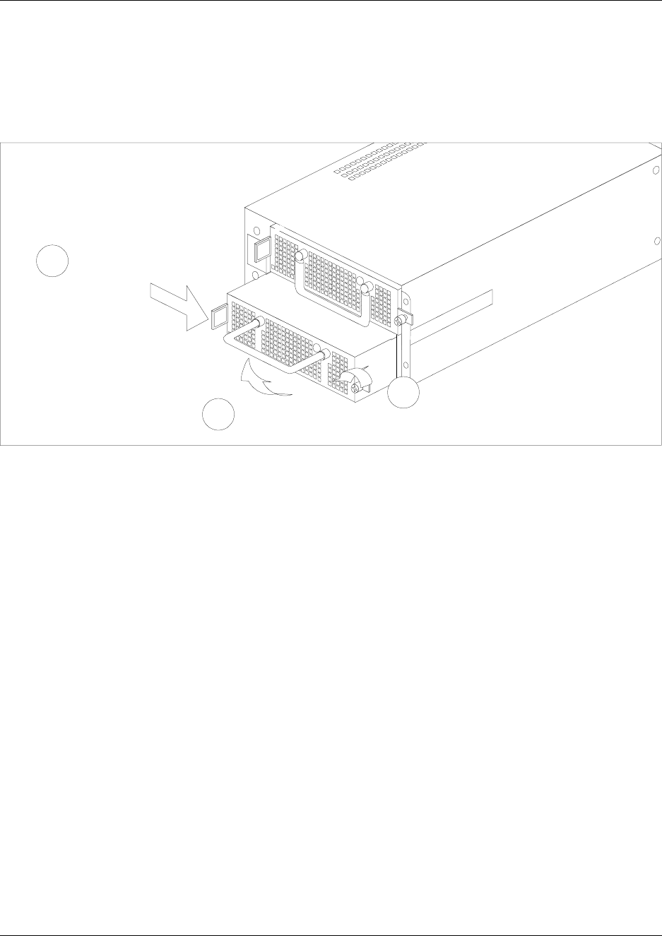
Chapter 9 Replace or Upgrade a Power Supply 215
Installation and Maintenance Guide
Note: If you are installing the redundant power supply for the first time, remove both power
supply modules from the redundant power supply cage. Remove the power supply modules
before you install the power supply in the platform base chassis (see Figure 143). Continue to
Step 5 of this procedure.
Figure 143 Remove the power supply module from the power supply cage
5Place the power supply module on a flat, clean, static-free surface.
6Repeat this step for any remaining power supply modules.
7This procedure is complete.
Rear view:
Power supply modules slide out of the
power supply cage.
Unfasten the power supply
module locking nut
Lift the power supply
module handle
Compress the locking
tab toward the handle
1
2
3

216 Chapter 9 Replace or Upgrade a Power Supply
P0993133 03

217
Installation and Maintenance Guide
Chapter 10
Replace Data Cards and Processing Hardware
This chapter describes how to replace data card and processing hardware components.
The following are field replaceable units (FRUs) for the BCM200 and BCM400 platforms:
• Base function tray
• Cards (WAN, MSC, Modem)
• Computer memory
• PEC cards
• Main card CMOS battery
System status LEDs
Ten LEDs on the front of the Business Communications Manager base function tray indicate PCI
card and hardware status.Use the LEDs to determine PCI device status as follows:
•Green LED on: Device is present and the driver is active
•Green LED flashing: Driver is not running
•Green LED off: Device is not present
Card Replacement Procedures
For a description of the function of each type of card on the Business Communications Manager
system, refer to “Data networking components” on page 62. The base function tray (BFT) contains
all of the cards described by the replacement procedures.
Use the procedures in this section to replace the following cards:
• Wide area network (WAN) card
• Media services card (MSC)
• Modem card
Warning: You must remove all of the connections to the Business Communications
Manager before you power the system down.
Failure to disconnect lines before power down can cause damage to the system.
Warning: Protect the hardware components against damage from electro-static
discharge. Always wear a ground wrist strap before you handle components. Always place
the components in static-free container.
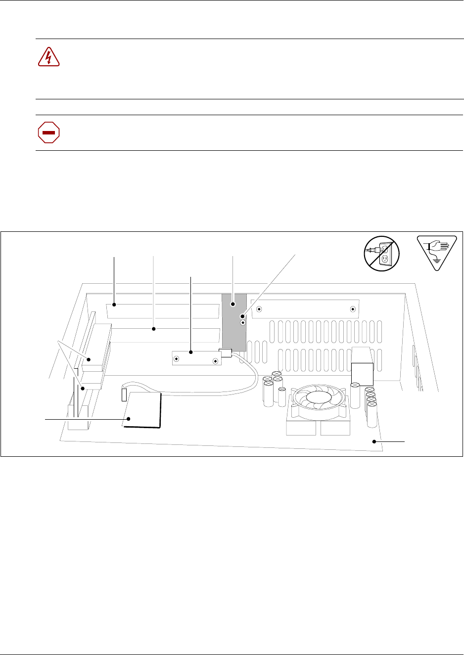
218 Chapter 10 Replace Data Cards and Processing Hardware
P0993133 03
•
Figure 144 shows an interior view of the base function tray (looking forward). The illustration
identifies the location of interior components and chassis features. Use the flow chart shown in
Figure 145 to replace the cards.
Figure 144 Base function tray interior components
Danger: Electrical shock warning.
Disconnect the power cord, telephone cables and network cables before opening the
computer.
Read and follow installation instructions carefully.
Caution: Use only a Nortel Networks approved replacement. Contact your account
representative for the current list of approved replacement parts.
PCI cover screw
Base function tray face
PCI cover plate
PCI Riser
card
connectors
Main card
WAN slot MSC slot
Modem
card
Modem card
interface
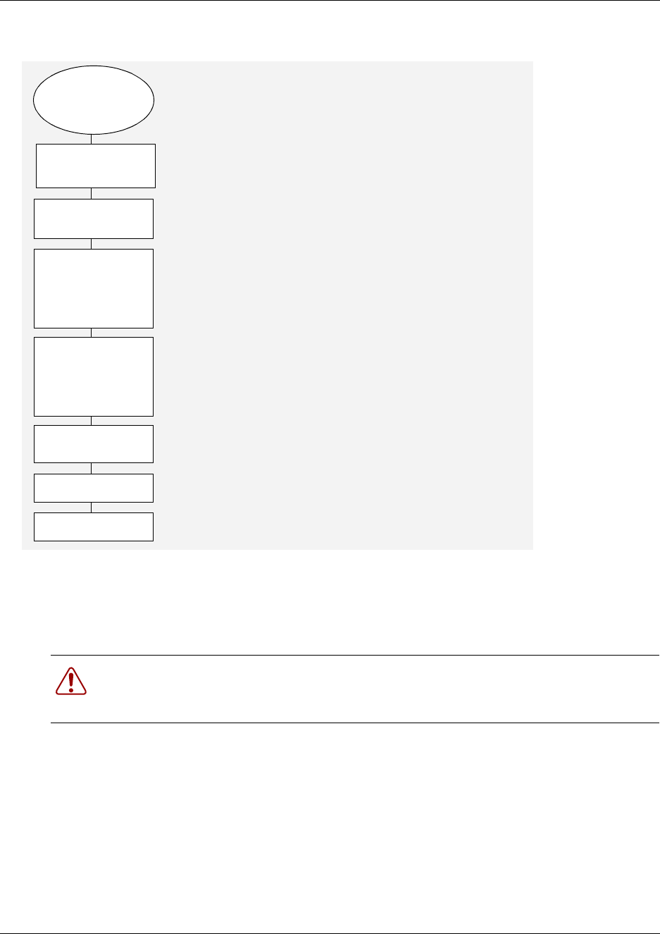
Chapter 10 Replace Data Cards and Processing Hardware 219
Installation and Maintenance Guide
Figure 145 Card replacement overview
Remove the WAN card
Use this procedure to remove the WAN card.
1If you still have access to the Unified Manager, shut down the system using the Shutdown
command. For details refer to “Shut down the system software” on page 145. Otherwise, skip
to step 2.
2Set up the server for maintenance, as described in “Shut down the system hardware” on page
146.
3Disconnect the Business Communications Manager from the AC power outlet.
4Disconnect any connectors from the front of the base function tray.
Warning: Protect the hardware components against damage from electro-static
discharge. Always wear a ground wrist strap before you handle components. Always place
the components in static-free container.
If possible,
do a software
shutdown
Perform BCM
maintenance
shutdown
Remove the base
function tray
Remove the
old card.
Install the new
card in the
same BFT slot
Insert the Base
function tray in the
BFT chassis cage
Restore unit to
operation
Check LEDs
END
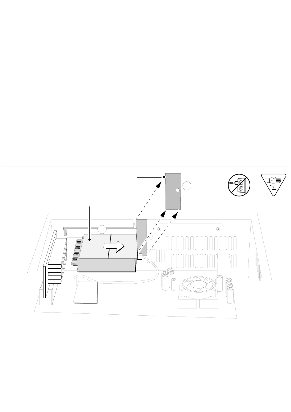
220 Chapter 10 Replace Data Cards and Processing Hardware
P0993133 03
5Remove the platform base chassis top cover. Refer to “Remove the platform base chassis top
cover” on page 161.
6Attach one end of the grounding strap to your wrist and the other end to a grounded metal
surface.
7Partially remove the base function tray from the platform base chassis. Ensure you do not
pinch, stretch or damage any cables. If required, remove the base function tray completely
from the platform base chassis (see “Remove the base function tray” on page 150).
8Remove the base function tray bezel. See “Remove the base function tray bezel” on page 153.
9At the front of the base function tray, loosen and remove the PCI cover plate screw (use a #2
Phillips screwdriver). Figure 146 shows an interior view of the base function tray. Place the
screw in a safe location.
10 Remove the PCI cover plate from the BFT chassis. Place the PCI cover plate in a safe location.
11 Use both hands to carefully hold the WAN card along the side edges. Push the WAN card away
from the PCI riser card connector.
Figure 146 Remove the WAN card and PCI cover plate
12 Remove the WAN card from the base function tray. Place the card in a safe, static-free and
clean location or container.
13 This procedure is complete.
PCI cover plate
WAN card
1
2
1. Remove the PCI
cover plate screw
2. Remove the WAN
card
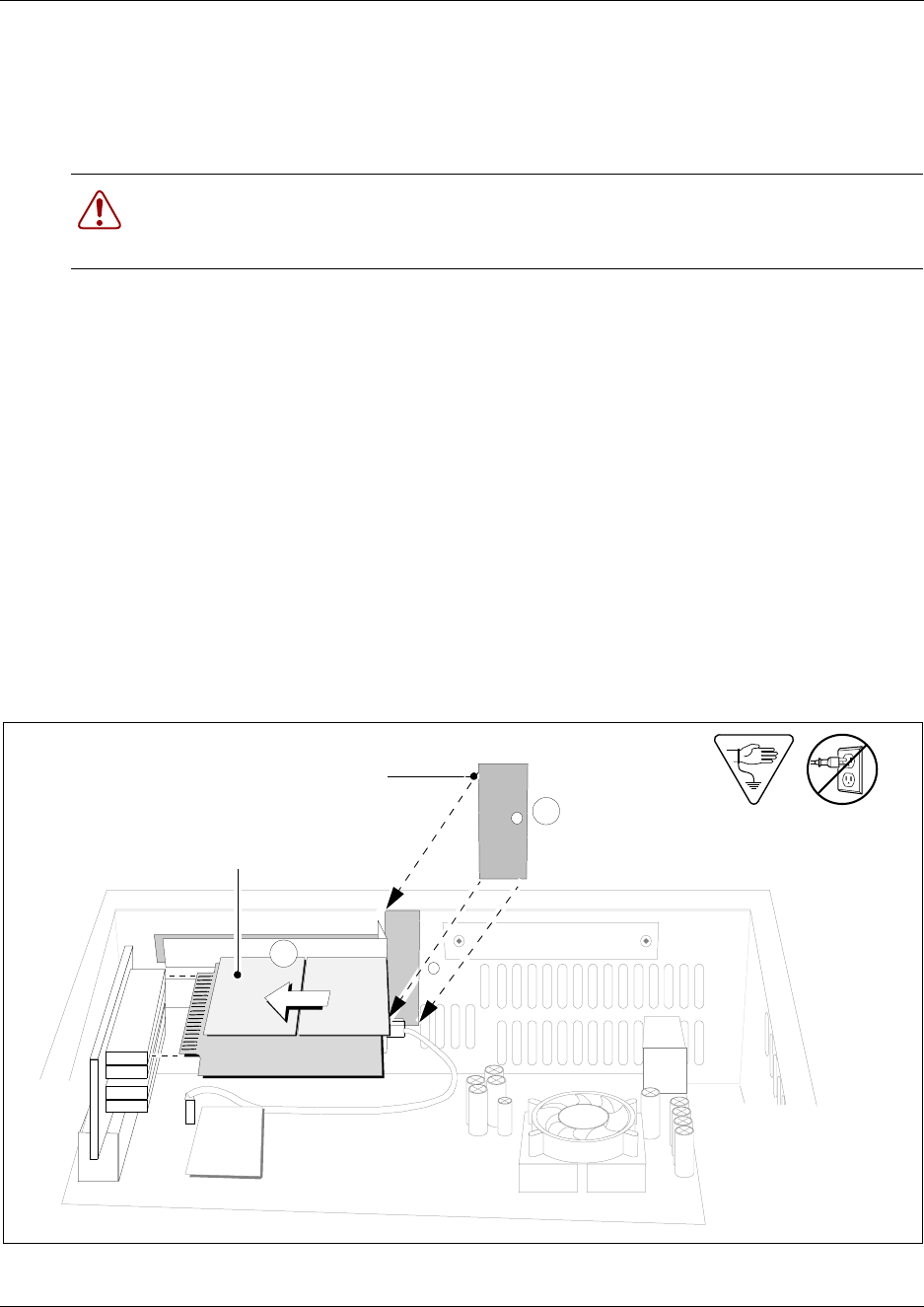
Chapter 10 Replace Data Cards and Processing Hardware 221
Installation and Maintenance Guide
Install the WAN card
Use this procedure to install a replacement WAN card. If you are installing a new WAN card for
the first time, refer to “Initialize a new WAN card” on page 222.
1Disconnect the Business Communications Manager from the AC power outlet.
2Partially remove the base function tray from the platform base chassis. If required, remove the
base function tray completely from the platform base chassis (see “Remove the base function
tray” on page 150).
3Remove the base function tray bezel (if applicable).
4Insert the WAN card in the same PCI slot from which you removed the original card. Refer to
Figure 147.
5Push firmly on the WAN card until it sits completely in the top PCI riser card connector.
6Position the PCI cover plate on the front of the base function tray such that the base function
tray and cover plate screw holes align.
7Position the PCI cover plate locking screw in the PCI cover plate. Tighten the PCI cover plate
locking screw until the plate is firmly set in place (see Figure 147).
Figure 147 Install the WAN card
Warning: Protect the hardware components against damage from electro-static
discharge. Always wear a ground wrist strap before you handle components. Always place
the components in static-free container.
PCI cover plate
WAN card
1
2
1. Install the
WAN card
2. Install the PCI
cover plate
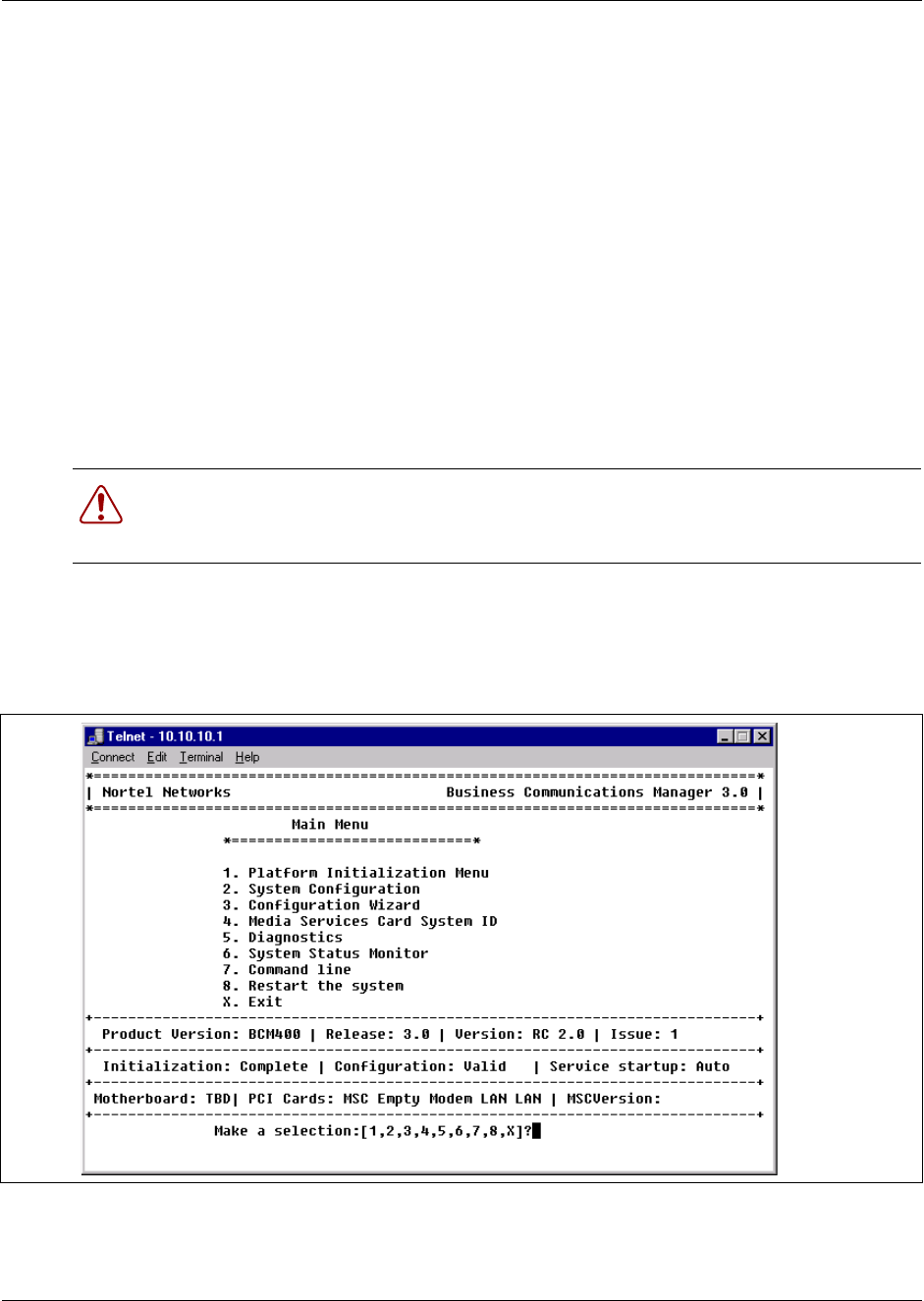
222 Chapter 10 Replace Data Cards and Processing Hardware
P0993133 03
8Partially insert the base function tray in the platform base chassis (see “Install the base
function tray” on page 151). Ensure you do not pinch or damage any cables.
9Install the base function tray bezel. See “Install the base function tray bezel” on page 154.
10 Move the base function tray latches to the locked position and install the latch screws.
11 Insert all connectors in the correct locations on the base function tray face.
12 Restore the unit to operation. For details, refer to “Restart the System after Maintenance” on
page 147.
13 This procedure is complete.
Initialize a new WAN card
Use this procedure to configure the Business Communications Manager to recognize a new WAN
card installation.
1When the Business Communications Manager system is operational, display the configuration
main menu through a telnet session. See “Display the configuration menus” on page 139.
Refer to Figure 148
Figure 148 Configuration main menu display
2Select option 8: Restart the system. Select “R” to confirm a restart.
3Observe the base function tray LEDs. Wait for the system to completely shut down - indicated
by flashing LEDs.
Warning: Protect the hardware components against damage from electro-static
discharge. Always wear a ground wrist strap before you handle components. Always place
the components in static-free container.
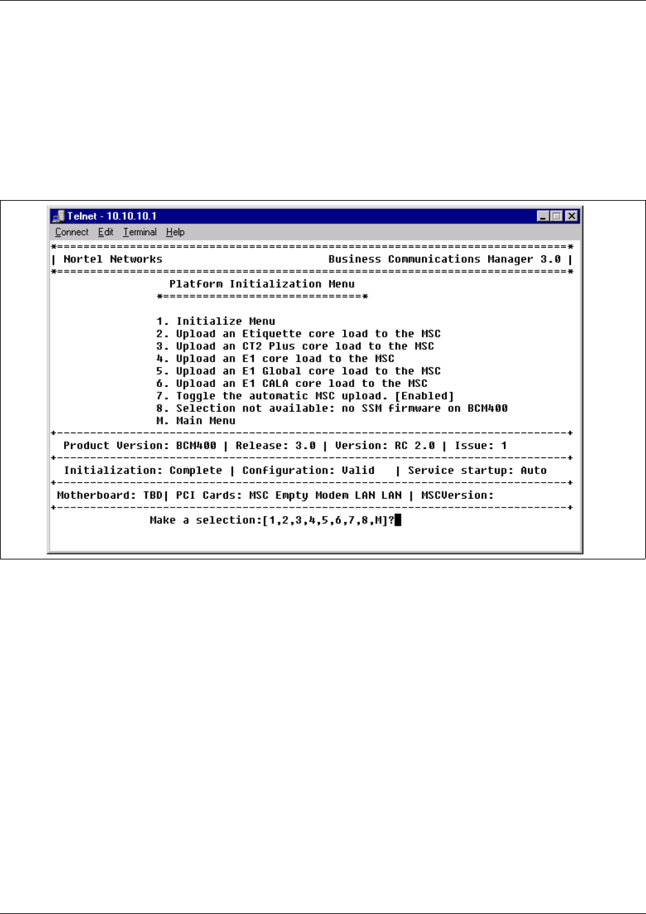
Chapter 10 Replace Data Cards and Processing Hardware 223
Installation and Maintenance Guide
4Perform the WAN card installation as described in the procedure: “Install the WAN card” on
page 221. Continue to the next step of this procedure when complete.
5When the system is powered-up, perform the following:
adisplay the configuration menu (see “Configuration main menu display” on page 222).
bSelect option 1 from the main menu to display the Platform Initialization Menu (see
Figure 149).
Figure 149 Platform initialization menu
6From the Platform Initialization menu, select option 1 to display the Initialize menu (see
Figure 150). The WAN card is shown in the PCI card inventory.
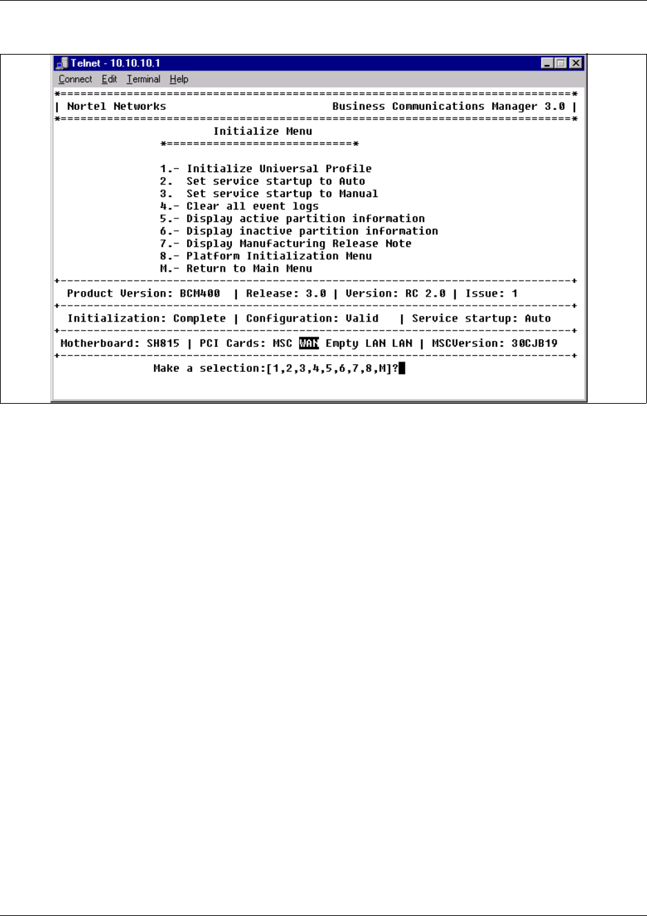
224 Chapter 10 Replace Data Cards and Processing Hardware
P0993133 03
Figure 150 Initialize menu
7From the Initialize menu, select option 1 - Initialize Universal Profile. The Business
Communications Manager performs a shutdown and reboot to enable the WAN card.
8This procedure is complete.

Chapter 10 Replace Data Cards and Processing Hardware 225
Installation and Maintenance Guide
Remove the media services card (MSC)
Use this procedure to remove the media services card from the base function tray.
1Ensure you have a current data backup of your system.
1If you still have access to the Unified Manager, shut down the system using the Shutdown
command. For details refer to “Shut down the system software” on page 145. Otherwise, skip
to step 2.
2Set up the server for maintenance, as described in “Shut down the system hardware” on page
146.
3Disconnect the Business Communications Manager from the AC power outlet.
4Disconnect any cables from the front of the base function tray.
5Attach one end of the grounding strap to your wrist and the other end to a grounded metal
surface.
6Partially remove the base function tray from the platform base chassis (See “Remove the base
function tray” on page 150). Do not exert force on the DS30 cables and connectors.
7Disconnect the DS30 cables.
8Remove the base function tray completely from the platform base chassis. Ensure you do not
pinch or damage any cables (see “Remove the base function tray” on page 150). Place the base
function tray on a flat, clean and static-free surface. Continue to the next step of this procedure
when complete.
9Remove the base function tray bezel. See “Remove the base function tray bezel” on page 153.
Continue to the next step of this procedure when complete.
10 At the front of the base function tray, loosen and remove the PCI cover plate screw (use a #2
Phillips screwdriver). Figure 146 shows an interior view of the base function tray. Place the
screw in a safe location.
11 Remove the PCI cover plate from the base function tray chassis. Place the PCI cover plate in a
safe location.
12 Remove the two chassis mounting screws that secure the MSC to the base function tray
chassis extension (at the rear of the MSC) - see Figure 151. Place the screws in a safe location.
Warning: Protect the hardware components against damage from electro-static
discharge. Always wear a ground wrist strap before you handle components. Always place
the components in static-free container.
Note: If you purchased optional Business Communications Manager applications that
require keycode activation, regenerate the keycodes after you re-install the replacement
MSC. For further information, see “Regenerating keycodes after system replacement” on
page 142 and “Install the media services card (MSC)” on page 226.
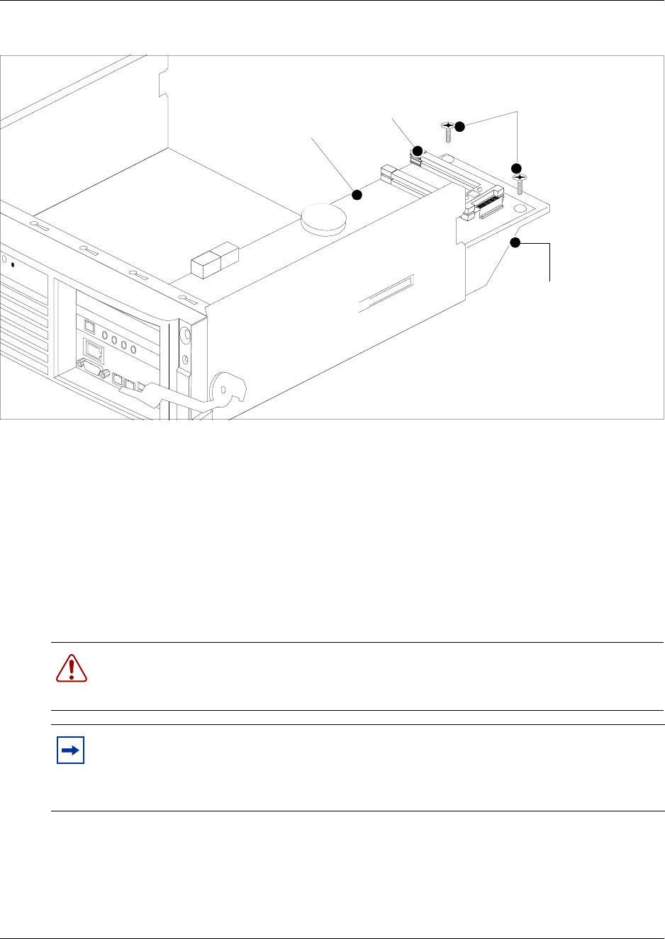
226 Chapter 10 Replace Data Cards and Processing Hardware
P0993133 03
Figure 151 MSC chassis mounting screws
13 Use both hands to carefully hold the card along the side edges. Push the card away from the
PCI riser card connector to disconnect the MSC.
14 Remove the MSC from the base function tray. Place the MSC on a flat, clean and static-free
surface.
15 This procedure is complete.
Install the media services card (MSC)
Use this procedure to install the media services card in the base function tray.
1Disconnect the Business Communications Manager from the wall power outlet.
2Attach one end of the grounding strap to your wrist and the other end to a grounded metal
surface.
3Position the MSC in the correct PCI riser card connector.
Warning: Protect the hardware components against damage from electro-static
discharge. Always wear a ground wrist strap before you handle components. Always place
the components in static-free container.
Note: If you purchased optional Business Communications Manager applications that
require keycode activation, regenerate the keycodes after you re-install the replacement
MSC. For further information, see “Regenerating keycodes after system replacement” on
page 142.
Base function tray
chassis extension
MSC
MSC chassis mounting
screws
PEC III slots

Chapter 10 Replace Data Cards and Processing Hardware 227
Installation and Maintenance Guide
4Push the card firmly and fully into the PCI riser card connector.
5Install the two chassis mounting screws at the rear of the MSC (see Figure 151).
6Position the PCI cover plate on the front of the base function tray such that the base function
tray and cover plate screw holes align.
7Position the PCI cover plate locking screw in the PCI cover plate. Tighten the PCI cover plate
locking screw until the plate is firmly set in place (see Figure 147).
8Install the base function tray bezel. See “Install the base function tray bezel” on page 154.
Continue to the next step in this procedure when complete.
9Partially install the base function tray in the platform base chassis.
10 Connect the DS30 connectors to the MSC.
11 Install the base function tray completely into the chassis. Be careful not to crimp the DS30
cables. (See “Install the base function tray” on page 151. Continue to the next step in this
procedure when complete.
12 Insert all connectors in the correct locations on the base function tray face.
13 Restore the Business Communications Manager to operation. For details, refer to “Restart the
System after Maintenance” on page 147. Continue to the next step in this procedure when
complete.
14 Restore your Business Communication Manager application keycodes if applicable. The step
applies only if you installed a new MSC. See “Regenerating keycodes after system
replacement” on page 142.
15 This procedure is complete.
Remove the modem card
Use this procedure to remove the modem card from the main card in the base function tray.
1If you still have access to the Unified Manager, shut down the system using the Shutdown
command. For details refer to “Shut down the system software” on page 145. Otherwise, skip
to step 2.
2Set up the Business Communications Manager for maintenance, as described in “Shut down
the system hardware” on page 146.
3Disconnect the Business Communications Manager from the AC power outlet.
4Attach one end of the grounding strap to your wrist and the other end to a grounded metal
surface.
5Remove the platform base chassis top. Refer to “Remove the platform base chassis top cover”
on page 161. Continue to the next step of this procedure when complete.
Warning: Protect the hardware components against damage from electro-static
discharge. Always wear a ground wrist strap before you handle components. Always place
the components in static-free container.
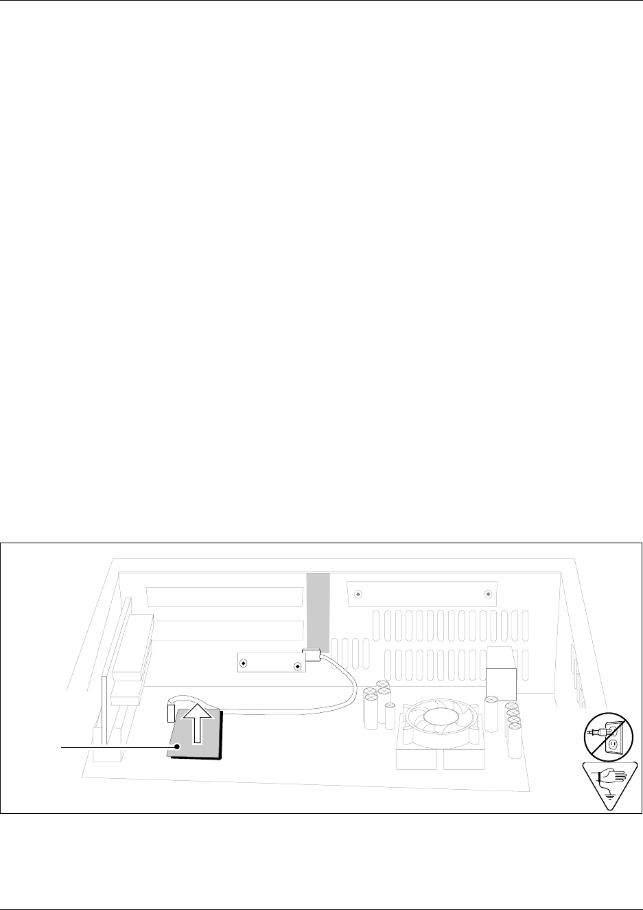
228 Chapter 10 Replace Data Cards and Processing Hardware
P0993133 03
6Disconnect any connectors from the front of the base function tray.
7Partially remove the base function tray from the platform base chassis (See “Remove the base
function tray” on page 150). Do not exert force on the DS30 cables and connectors. Ensure
you do not pinch, stretch or damage any cables.
8Remove the WAN card if applicable (see “Remove the WAN card” on page 219). Continue to
the next step when complete.
9Disconnect the DS30 cables from the MSC.
10 Remove the base function tray completely from the platform base chassis. Ensure you do not
pinch, stretch or damage any cables. Refer to “Remove the base function tray” on page 150.
Place the base function tray on a flat, clean and static-free surface. Continue to the next step of
this procedure when complete.
11 Remove the base function tray bezel. See “Remove the base function tray bezel” on page 153.
Continue to the next step when complete.
12 Loosen and remove the PCI cover plate screw (use a #2 Phillips screwdriver - see Figure 146).
Place the PCI cover plate screw in a safe location.
13 Remove the PCI cover plate from the base function tray chassis (see Figure 146 on page 220).
Place the PCI cover plate in a safe location.
14 Remove the MSC. Refer to “Remove the media services card (MSC)” on page 225. Continue
to the next step of this procedure when complete.
15 Locate the modem card on the main card.
16 Carefully grasp the modem card edges with your finger tips. Carefully pull the modem card
away from the main card. Place the modem card in a clean, safe and static-free location.
Figure 152 Modem card
17 Carefully grasp the modem card guide pin and remove. Place the pin in a safe location.
18 This procedure is complete.
Base
function
tray face
Modem
card

Chapter 10 Replace Data Cards and Processing Hardware 229
Installation and Maintenance Guide
Install the modem card
Use this procedure to install a modem card in a base function tray. This procedure assumes the
base function tray is not installed in the platform base chassis.
1Obtain a correct and functional modem card.
2Disconnect the Business Communications Manager from the AC power outlet.
3Attach one end of the grounding strap to your wrist and the other end to a grounded metal
surface.
4Install the modem card guide pin.
5Carefully grasp the new modem card with your finger tips.
6Install the modem card in the correct location on the main card. Ensure the modem card pins
correctly align with the main card modem connectors and modem guide pin.
7Gently push on the modem card with your fingertips until it fully seats in the main card
modem connectors.
8If applicable, connect the RJ11 modem card connector to the main card socket.
9Install the MSC in the correct PCI riser card connector. See “Install the media services card
(MSC)” on page 226. When complete, continue to the next step of this procedure.
10 Install the two chassis mounting screws that secure the MSC to the base function tray chassis
extension (at the rear of the MSC). See Figure 151.
11 Position the WAN card (if applicable) in the top PCI riser card connector. See “Install the
WAN card” on page 221. When complete, continue to the next step of this procedure.
12 Partially install the base function tray in the platform base chassis.
13 Connect the DS30 connectors to the MSC.
14 Position the PCI cover plate on the front of the base function tray such that the base function
tray and cover plate screw holes align.
15 Position the PCI cover plate locking screw in the PCI cover plate. Tighten the PCI cover plate
locking screw until the plate is firmly set in place (see Figure 147).
16 Push the base function tray completely into the chassis (see “Install the base function tray” on
page 151). Ensure you do not pinch or damage any cables. When complete, continue to the
next step of this procedure.
17 Restore the Business Communications Manager to operation. For details, refer to “Restart the
System after Maintenance” on page 147. When complete, continue to the next step of this
procedure.
18 This procedure is complete.
Warning: Protect the hardware components against damage from electro-static
discharge. Always wear a ground wrist strap before you handle components. Always place
the components in static-free container.
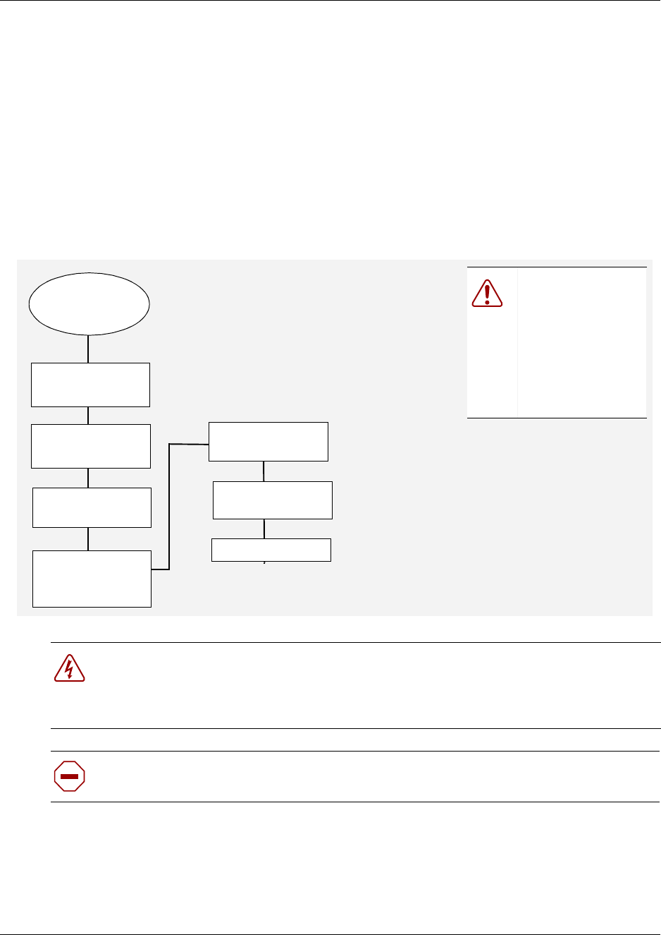
230 Chapter 10 Replace Data Cards and Processing Hardware
P0993133 03
Replace the Processor Expansion Card (PEC)
The BCM200 is equipped with one Processor expansion card (PEC III) mounted on the Media
services card (MSC). The BCM400 is equipped with two Processor expansion cards (PEC III)
mounted on the Media services card (MSC). The PECs provide signal processing capabilities for
such applications as voice mail and IP telephony applications.
This section describes the processes to remove and replace a PEC module.
Figure 153 provides an overview of the process for replacing the PEC.
Figure 153 PEC replacement overview
Danger: Electrical shock warning.
Disconnect the power cord, telephone cables and network cables before opening the
computer.
Read and follow installation instructions carefully.
Caution: Use only a Nortel Networks approved replacement. Contact your account
representative for the current list of approved replacement parts.
Set up unit for
maintenance
Remove the top
cover
Restore unit to
operation
If required,
remove PEC
module from MSC
Install the
PEC
Test system
Do a software
shutdown
Ensure you
have a current
data backup.
Warning:
Incorrect handling
of the PEC during
installation could
result in loss of
telephony
programming.
Chapter 10 Replace Data Cards and Processing Hardware 231
Installation and Maintenance Guide
Remove the processor expansion card (PEC)
Use this procedure to remove PECs from a Business Communications Manager MSC.
1Ensure you have a current data backup of your system.
2Shut down the system using the Shutdown command. For details refer to “Shut down the
system software” on page 145. When complete, continue to the next step of this procedure.
3Set up the server for maintenance, as described in “Shut down the system hardware” on page
146. When complete, continue to the next step of this procedure.
4Disconnect the Business Communications Manager from the wall power outlet.
5Attach one end of the grounding strap to your wrist and the other end to a grounded metal
surface.
6Partially remove the base function tray from the platform base chassis. Ensure you do not
pinch, stretch or damage any cables.
7Grasp the top edge of the PEC you want to remove and it pull out. Place the PEC in a safe and
static-free container. Refer to Figure 154.
Warning: Possible data loss
Ensure that you do not touch the PEC casing to any of the components on the MSC. This
may cause shorting, which can erase memory or cause a loss of telephony programming.
If this occurs, complete the removal of the PEC, and then restore the data from your
backup medium (upon re-installation - see “Install a processor expansion card (PEC)” on
page 233).
Warning: Protect the hardware components against damage from electro-static
discharge. Always wear a ground wrist strap before you handle components. Always place
the components in static-free container.
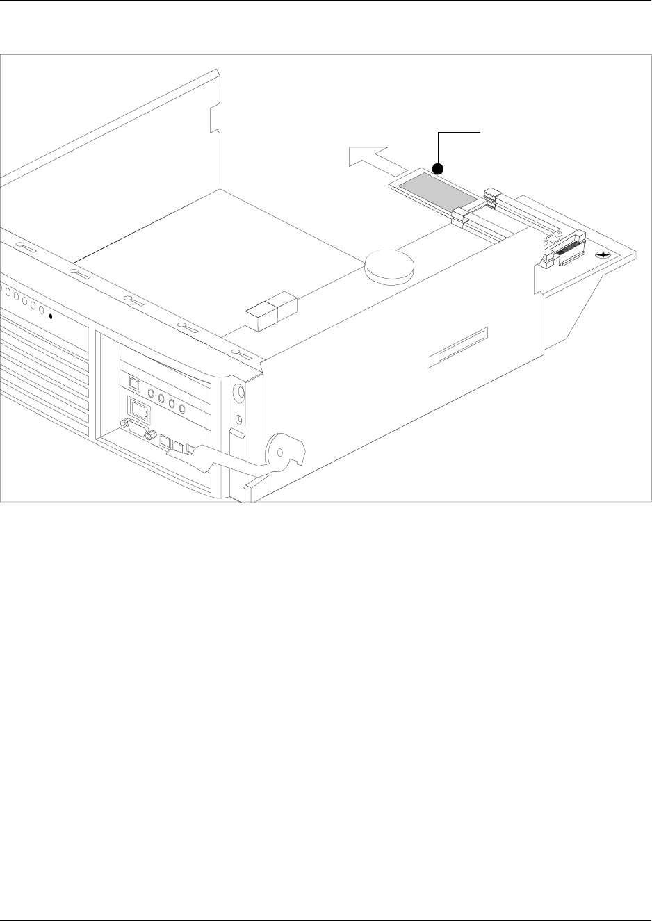
232 Chapter 10 Replace Data Cards and Processing Hardware
P0993133 03
Figure 154 Remove the processor expansion card (PEC III)
8This procedure is complete.
Processor expansion card
Chapter 10 Replace Data Cards and Processing Hardware 233
Installation and Maintenance Guide
Install a processor expansion card (PEC)
When you replace or add PECs, ensure you follow the directions for shutting down the system.
Ensure you have a current data backup of your system. This procedure assumes the base function
tray is partially removed from the platform base chassis.
Use this procedure to correctly install a PEC.
1Disconnect the Business Communications Manager from the wall power outlet.
2Attach one end of the grounding strap to your wrist and the other end to a grounded metal
surface.
3Decide which slot you are going to install the PEC into on the MSC. If you have more than
one card holder (BCM400), populate one card holder completely at a time. Populate the
bottom slot first, then insert additional PEC on top.
4Line the card up between the rails of the slot. Ensure the card label is face-up.
5Carefully slide the PEC into the slot until it is firmly seated.
Warning: Possible data loss
Ensure that you do not touch the PEC casing to any of the components on the MSC. This
may cause shorting, which can erase memory or cause a loss of telephony programming.
If this occurs, complete the installation of the PEC, and then restore the data from your
backup medium.
Warning: Protect the hardware components against damage from electro-static
discharge. Always wear a ground wrist strap before you handle components. Always place
the components in static-free container.
Note: Do not force the card into its slot. If the PEC does not slide in easily, check the
alignment.
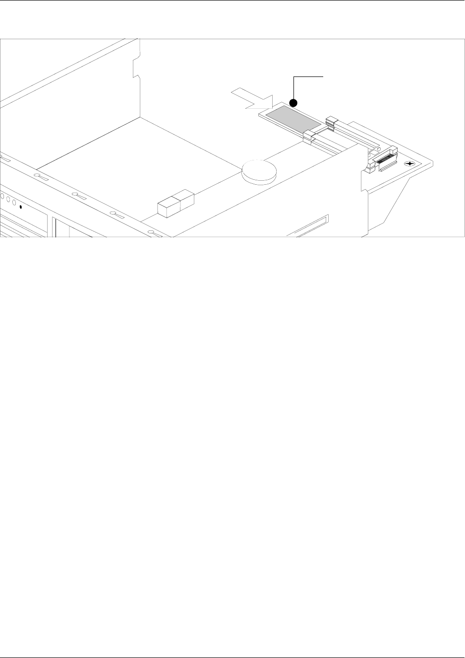
234 Chapter 10 Replace Data Cards and Processing Hardware
P0993133 03
Figure 155 Insert the processor expansion card (PEC III)
6Completely insert the base function tray into the platform base chassis (see “Install the base
function tray” on page 151). Continue to the next step of this procedure when complete.
7Restore the unit to operation. Refer to “Restart the System after Maintenance” on page 147.
8This procedure is complete.
Processor expansion card
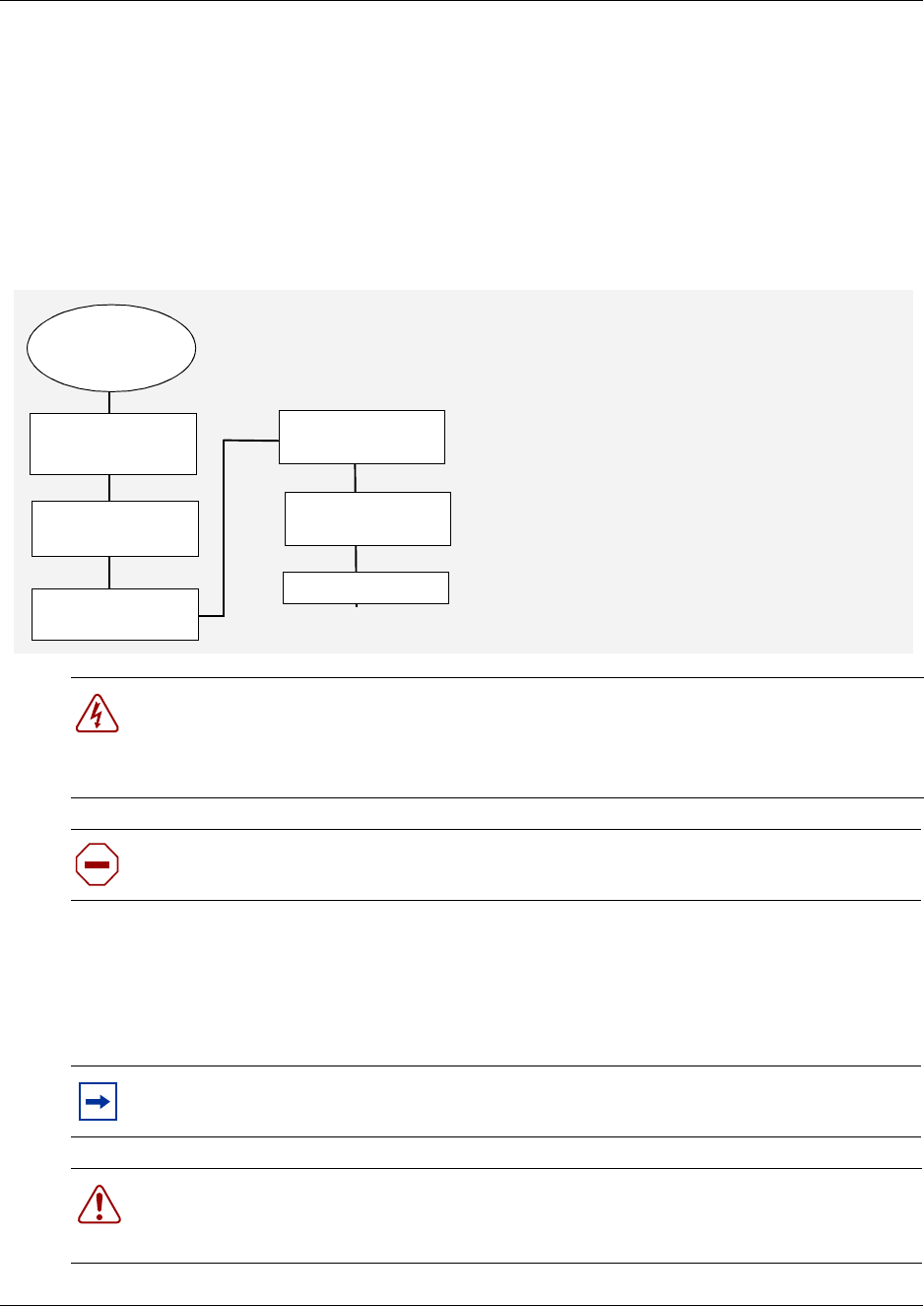
Chapter 10 Replace Data Cards and Processing Hardware 235
Installation and Maintenance Guide
Replace Memory
The Business communication manager is equipped with 256 MB of Random Access Memory
(RAM). The memory resides on a Dual In-line Memory Module (DIMM) on the main card. The
main card contains space to add a second DIMM, or you can upgrade the existing DIMM.
Figure 156 provides an overview of the process for replacing or adding memory chips.
Figure 156 Memory replacement overview
Remove the dual in-line memory module (DIMM) card
Use this procedure to remove a DIMM when the circuit fails or when you want to increase the
amount of RAM in the Business Communications Manager.
Danger: Risk of shock.
Disconnect the power cord, telephone cables and network cables before opening the
computer.
Read and follow installation instructions carefully.
Caution: Use only a Nortel Networks approved replacement. Contact your account
representative for the current list of approved replacement parts
Note: There must be at least one DIMM installed in the Business Communications
Manager in order for the system to function.
Warning: Protect the hardware components against damage from electro-static
discharge. Always wear a ground wrist strap before you handle components. Always place
the components in static-free container.
Do a software
shutdown
Set up unit for
maintenance
Remove the BFT Restore unit to
operation
Pull DIMM off
motherboard
Install a new
DIMM
Test system

236 Chapter 10 Replace Data Cards and Processing Hardware
P0993133 03
1If you still have access to the Unified Manager, shut down the system using the Shutdown
command. For details refer to “Shut down the system software” on page 145. Otherwise, skip
to step 2.
2Set up the platform base hardware for maintenance, as described in “Shut down the system
hardware” on page 146.
3Disconnect the Business Communications Manager from the AC power outlet.
4Disconnect any connectors from the front of the base function tray.
5Remove the platform base chassis cover. See “Remove the platform base chassis top cover” on
page 161. Continue to the next step in this procedure when complete.
6Attach one end of the grounding strap to your wrist and the other end to a grounded metal
surface.
7Partially remove the base function tray from the platform base chassis. Ensure you do not
pinch, stretch or damage any cables.
8Remove the base function tray bezel. See “Remove the base function tray bezel” on page 153.
Continue to the next step in this procedure when complete.
9Remove the WAN card (if applicable). See “Remove the WAN card” on page 219. Continue to
the next step in this procedure when complete.
10 Detach the DS30 cable connectors from the MSC.
11 Remove the base function tray completely from the platform base chassis. Ensure you do not
pinch, stretch or damage any cables. See “Remove the base function tray” on page 150.
Continue to the next step of this procedure when complete.
12 Remove the media services card (see “Remove the media services card (MSC)” on page 225).
Continue to the next step of this procedure when complete.
13 Carefully push down on the fastening tabs on either side of the DIMM you want to remove. As
you press down on the fastening tabs, the DIMM lifts out of the DIMM slot.
14 Grasp both ends of the DIMM with your fingertips. Lift the DIMM up and away from the
DIMM slot (see Figure 157 on page 236). Place the DIMM in a static-free container.
Figure 157 Remove and replace the dual in-line memory module
15 This procedure is complete.
Base function
tray front
Chapter 10 Replace Data Cards and Processing Hardware 237
Installation and Maintenance Guide
Install the dual in-line memory module (DIMM) card
Use this procedure to install a replacement DIMM or when you want to increase the amount of
RAM in the Business Communications Manager.
1Position and correctly align the new DIMM (edge connectors first) into the connector.
2Carefully and firmly press down on the top of the DIMM card with your thumbs. At the same
time, use your index fingers to move the fastening tabs inward toward the card. When the card
is completely inserted in the connector, the fastening tabs clip to the side of the DIMM card.
3Install the media services card (see “Install the media services card (MSC)” on page 226).
Continue to the next step of this procedure when complete.
4Partially install the base function tray in the platform base chassis.
5Install the WAN card (if applicable). See “Install the WAN card” on page 221. Continue to the
next step of this procedure when complete.
6Connect the DS30 connectors to the MSC.
7Completely install the base function tray in the platform base chassis (see “Install the base
function tray” on page 151). Ensure you do not pinch or damage any cables.
8Install the base function tray bezel. See “Install the base function tray bezel” on page 154.
Continue to the next step of this procedure when complete.
9Insert all connectors in the correct locations on the base function tray face.
10 Restore the Business Communications Manager to operation. Refer to “Restart the System
after Maintenance” on page 147 for details. Continue to the next step of this procedure when
complete.
11 This procedure is complete.
Note: There must be at least one DIMM installed in the Business Communications
Manager in order for the system to function.
Warning: Protect the hardware components against damage from electro-static
discharge. Always wear a ground wrist strap before you handle components. Always place
the components in static-free container.
Note: The DIMM has two notches on the edge connector. Position the DIMM so
that one of the notches is on the side of the slot nearest to the Business
Communications Manager cards.
Note: Do not force the DIMM into its slot. If the DIMM does not slide in easily,
check the alignment of the DIMM.
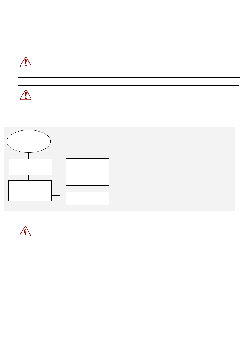
238 Chapter 10 Replace Data Cards and Processing Hardware
P0993133 03
Replace the Clock/Calendar Battery
The clock/calendar battery supplies the power required to keep the CMOS information current if
there is a power failure. Figure 153 provides an overview of the process of replacing this
component.
Figure 158 Battery replacement overview
Warning: You must replace the battery with a CR2032, 3v Maxell coin cell battery. Do
not use any other manufacturer because this may invalidate the safety approval of the
Business Communications Manager and possibly cause a fire or explosion.
Warning: Protect the hardware components against damage from electro-static
discharge. Always wear a ground wrist strap before you handle components. Always place
the components in static-free container.
Danger: Disconnect the power cord, telephone cables and network cables before opening
the computer.
Read and follow installation instructions carefully.
Do a software
shutdown
Set up unit for
maintenance
Restore unit to
operation
CAREFULLY
lift battery off
motherboard
Install
new battery
WARNING:
+ faces up
Chapter 10 Replace Data Cards and Processing Hardware 239
Installation and Maintenance Guide
Remove the clock/calendar battery
Use this procedure to remove the clock/calendar battery.
1If you still have access to the Unified Manager, shut down the system using the Shutdown
command. For details refer to “Shut down the system software” on page 145. Otherwise, skip
to step 2.
2Set up the server for maintenance, as described in “Shut down the system hardware” on page
146.
3Disconnect the Business Communications Manager from the AC power outlet.
4Attach one end of the grounding strap to your wrist and the other end to a grounded metal
surface.
5Disconnect any connectors from the front of the base function tray.
6Partially remove the base function tray from the platform base chassis. Do not crimp, stretch
or damage cables or connectors.
7Remove the base function tray bezel. See “Remove the base function tray bezel” on page 153.
Continue to the next step of this procedure when complete.
8Remove the WAN card (if applicable). See “Remove the WAN card” on page 219. Continue to
the next step of this procedure when complete.
9Disconnect the DS30 cables from the MSC. Do not crimp, stretch or damage cables or
connectors.
10 Completely remove the base function tray from the platform base chassis. See “Remove the
base function tray” on page 150. Continue to the next step of this procedure when complete.
11 Remove the media services card (see “Remove the media services card (MSC)” on page 225).
Continue to the next step of this procedure when complete.
12 Use your finger to carefully lift the battery out of the socket. For the location of the battery
socket, refer to Figure 159.
Warning: Protect the hardware components against damage from electro-static
discharge. Always wear a ground wrist strap before you handle components. Always place
the components in static-free container.
Caution: Do not use any type of tool to remove the battery.
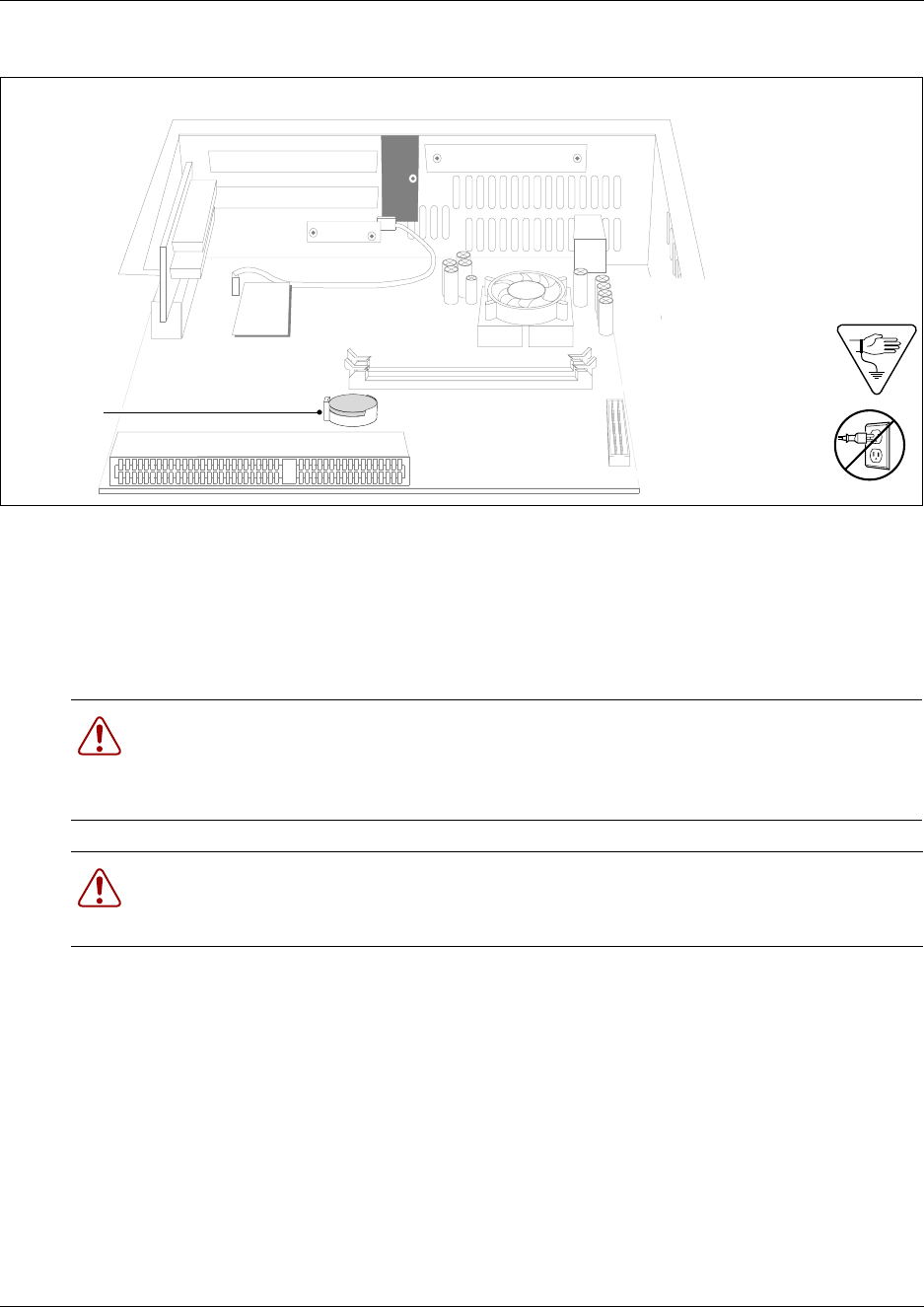
240 Chapter 10 Replace Data Cards and Processing Hardware
P0993133 03
Figure 159 Removing the clock/calendar battery
13 This procedure is complete.
Install a new clock/calendar battery
Use this procedure to insert a clock/calendar battery into the base function tray.
1Remove the old battery. See “Remove the Clock/Calendar battery” on page 239.
2Ensure you have the positive side of the battery facing up when you position it in the socket.
3Push down until the battery snaps into the socket.
4Install the media services card. See “Install the media services card (MSC)” on page 226.
Continue to the next step of this procedure when complete.
5Install the WAN card (if applicable). See “Install the WAN card” on page 221. Continue to the
next step of this procedure when complete.
6Partially insert the base function tray into the platform base chassis.
7Connect the DS30 connectors to the MSC.
Warning: There is a danger of explosion if you do not replace the battery correctly.
You must replace the battery with a CR2032, 3v Maxell coin cell battery.
The positive side of the battery must face up.
The battery must sit securely in the battery socket.
Warning: Protect the hardware components against damage from electrostatic discharge.
Always wear a ground wrist strap before you handle components. Always place the
components in static-free container.
Base function tray front
CMOS
battery
The battery is located
under the edge of the
power supply

Chapter 10 Replace Data Cards and Processing Hardware 241
Installation and Maintenance Guide
8Position the PCI cover plate on the front of the base function tray such that the base function
tray and cover plate screw holes align.
9Position the PCI cover plate locking screw in the PCI cover plate. Tighten the PCI cover plate
locking screw until the plate is firmly set in place (see Figure 147).
10 Install the base function tray bezel (see “Install the base function tray bezel” on page 154).
Continue to the next step in this procedure when complete.
11 Completely insert the base function tray into the platform base chassis. See “Install the base
function tray” on page 151. Continue to the next step of this procedure when complete.
12 Restore the Business Communications Manager to operation. For details, refer to “Restart the
System after Maintenance” on page 147. Continue to the next step of this procedure when
complete.
13 This procedure is complete.

242 Chapter 10 Replace Data Cards and Processing Hardware
P0993133 03
243
Installation and Maintenance Guide
Chapter 11
Install Telephones and Peripherals
You can add telephones and peripherals before or after you initialize your system. Set
configuration is determined by the which station module you are using, and what DS30 channel
settings you chose for the module. Refer to Chapter 13, “Install Analog Terminal Adapters,” on
page 277.
The system creates default settings for the telephone DN records when it is first initialized. The
settings are based on which telephony profile you chose. To change these settings, use the Unified
Manager application. Specific instructions for configuring telephone operation through the
Unified Manager are contained in the Business Communications Manager 3.0 Programming
Operations Guide.
System Telephones
The Business Communications Manager system supports a number of analog, digital, IP telephony
and cordless telephones. Refer to “Telephones and adapters” on page 85 for a description of the
sets the system supports.
Analog telephones are supported either through analog modules (ASMs) or by connecting to a
digital module through an Analog Terminal Adapter 2 (ATA2).
Documentation describing installation and set features is supplied with each piece of equipment.
Analog terminal adapter
The Analog Terminal Adapter 2 (ATA 2) connects a standard analog voice device or data
communication device to a digital line connector on the Business Communications Manager
system.
Refer to Chapter 13, “Install Analog Terminal Adapters,” on page 277 for the requirements and
procedure for installing the device.
Note: Programming occurs on the set when the Business Communications Manager
recognizes the set on the system.
Caution: Do not use telephones as off-premises extensions (OPX)
Digital and analog telephones must not be installed on any connections not protected by
building equipment.
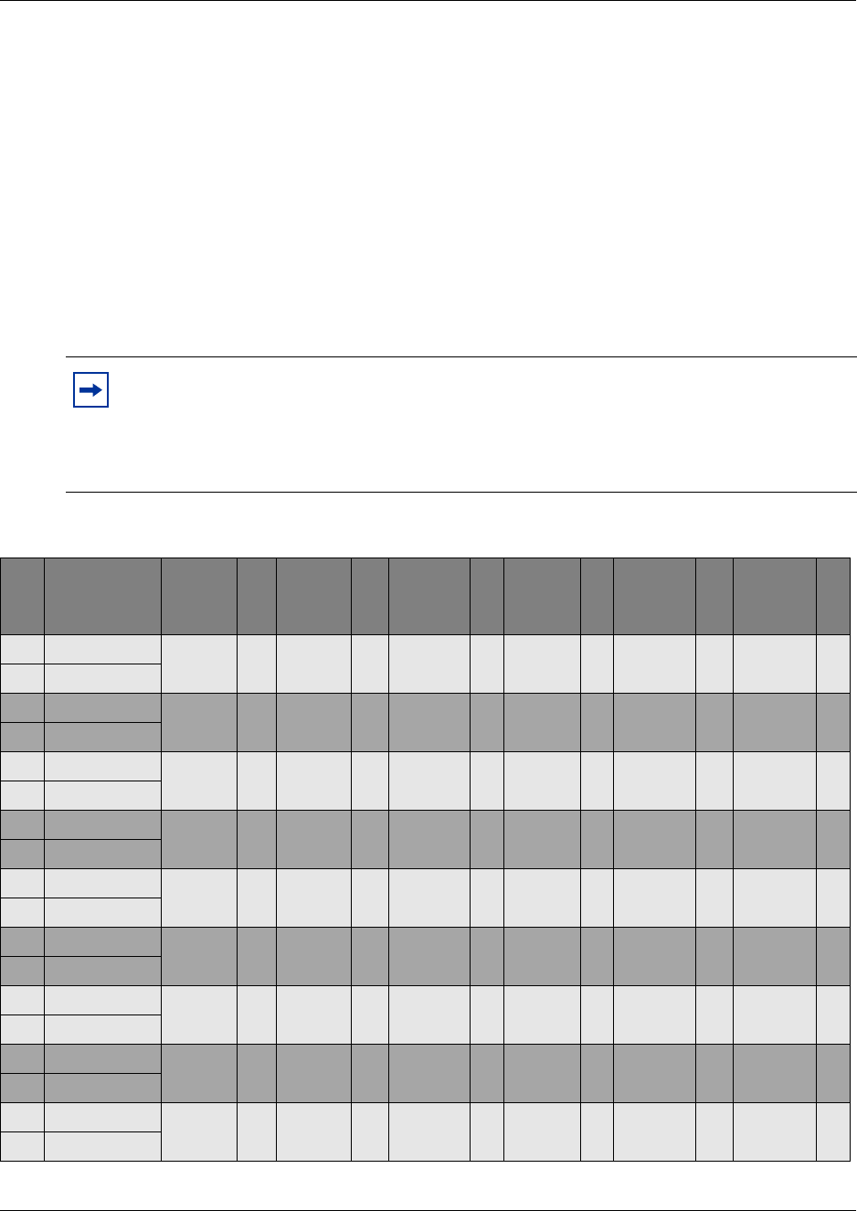
244 Chapter 11 Install Telephones and Peripherals
P0993133 03
Central answering position (CAP)
The Central Answering Position (CAP) module connects to an M7324 telephone. The module
provides 48 additional memory buttons. For installation procedures for the CAP, refer to the
installation documents that came with the CAP.
Telephone port and DN cross-reference
The media bay module the analog and digital telephones are connected to dictates DNs and port
numbers. Use Table 25 to identify which port your telephones are connected to. For future
reference, put a checkmark beside the ports where there are sets installed.
Note: The following table is based on a system with three-digit DNs, with a start DN of
221. If your system has longer DNs, the system automatically adds a 2 for each additional
DN length unit. i.e. 221 becomes 2221.
Appendix C, “Media Bay Module Combinations,” on page 345 contains a blank table to
use if you changed the start DN on your system.
Table 25 Cross referencing ports and DNs
Pin Wire color
DS 30
channel
2
DS 30
channel
3
DS 30
channel
4
DS 30
channel
5
DS 30
channel
6
DS 30
channel
7
26 White-Blue DN 221
Port 201
DN 237
Port 301
DN 253
Port 401
DN 269
Port 501
DN 285
Port 601
DN 301
Port 701
1Blue-White
27 White-Orange DN 222
Port 202
DN 238
Port 302
DN 254
Port 402
DN 270
Port 502
DN 286
Port 602
DN 302
Port 702
2Orange-White
28 White-Green DN 223
Port 203
DN 239
Port 303
DN 255
Port 403
DN 271
Port 503
DN 287
Port 603
DN 303
Port 703
3Green-White
29 White-Brown DN 224
Port 204
DN 240
Port 304
DN 256
Port 404
DN 272
Port 504
DN 288
Port 604
DN 304
Port 704
4Brown-White
30 White-Slate DN 225
Port 205
DN 241
Port 305
DN 257
Port 405
DN 273
Port 505
DN 289
Port 605
DN 305
Port 705
5Slate-White
31 Red-Blue DN 226
Port 206
DN 242
Port 306
DN 258
Port 406
DN 274
Port 506
DN 290
Port 606
DN 306
Port 706
6Blue-Red
32 Red-Orange DN 227
Port 207
DN 243
Port 307
DN 259
Port 407
DN 275
Port 507
DN 291
Port 607
DN 307
Port 707
7Orange-Red
33 Red-Green DN 228
Port 208
DN 244
Port 308
DN 260
Port 408
DN 276
Port 508
DN 292
Port 608
DN 308
Port 708
8Green-Red
34 Red-Brown DN 229
Port 209
DN 245
Port 309
DN 261
Port 409
DN 277
Port 509
DN 293
Port 609
DN 309
Port 709
9Brown-Red
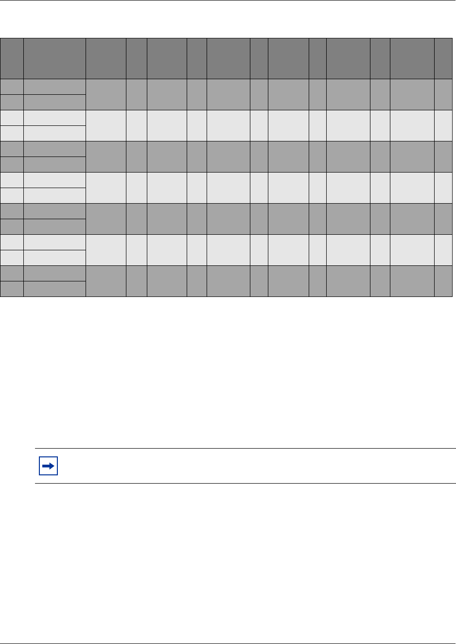
Chapter 11 Install Telephones and Peripherals 245
Installation and Maintenance Guide
Emergency Telephone Installation
You can use the emergency telephone to make calls when there is no power to the Business
Communications Manager system.
To install an emergency telephone on the Business Communications Manager system, connect a
single line analog telephone to the auxiliary port on the CTM. When you make a call from the
emergency telephone, the auxiliary port uses the telephone line connected to the Line 1 port of the
CTM.
Use the following steps to install the emergency telephone.
1Connect a single line analog telephone to the auxiliary port on the CTM.
2Connect an analog PSTN line cable to the Line 1 port of the CTM.
35 Red-Slate DN 230
Port 210
DN 246
Port 310
DN 262
Port 410
DN 278
Port 510
DN 294
Port 610
DN 310
Port 710
10 Slate-Red
36 Black-Blue DN 231
Port 211
DN 247
Port 311
DN 263
Port 411
DN 279
Port 511
DN 295
Port 611
DN 311
Port 711
11 Blue-Black
37 Black-Orange DN 232
Port 212
DN 248
Port 312
DN 264
Port 412
DN 280
Port 512
DN 296
Port 612
DN 312
Port 712
12 Orange-Black
38 Black-Green DN 233
Port 213
DN 249
Port 313
DN 265
Port 413
DN 281
Port 513
DN 297
Port 613
DN 313
Port 713
13 Green-Black
39 Black-Brown DN 234
Port 214
DN 250
Port 314
DN 266
Port 414
DN 282
Port 514
DN 298
Port 614
DN 314
Port 714
14 Brown-Black
40 Black-Slate DN 235
Port 215
DN 251
Port 315
DN 267
Port 415
DN 283
Port 515
DN 299
Port 615
DN 315
Port 715
15 Slate-Black
41 Yellow-Blue DN 236
Port 216
DN 252
Port 316
DN 268
Port 416
DN 284
Port 516
DN 300
Port 616
DN 316
Port 716
16 Blue-Yellow
TIP: You can connect an emergency telephone to every CTM installed on your Business
Communications Manager system.
Table 25 Cross referencing ports and DNs (Continued)
Pin Wire color
DS 30
channel
2
DS 30
channel
3
DS 30
channel
4
DS 30
channel
5
DS 30
channel
6
DS 30
channel
7

246 Chapter 11 Install Telephones and Peripherals
P0993133 03
Install IP Telephones
The Business Communications Manager emobility strategy includes support for the Nortel
Networks i2004 and i2002 IP telephones, the Nortel Networks i2050 Software Phone, and the
NetVision and the NetVision Data portable handsets.
The system can be set to automatically assign DNs to the Nortel IP telephones. If you choose to
manually assign DNs, choose DNs from the following digital range, if possible:
Ensure that the DN type in each DN record is set to IP telephony.
• B1 line DNs can default to unused DNs from 221 to 376.
• B2 line DNs can default to unused DNs from 377 to 472.
NetVision DNs are assigned to the handsets through the H.323 section under IP Telephony on the
Unified Manager. Use the DNs within the ranges described above. If no DN is specified in the
record, the system will automatically assign one when the handset connects to the system.
For details about configuring DN records for the IP telephones and the NetVision telephones, refer
to the IP Telephony Configuration Guide.
Install Radio-Based Portable Systems
There are three radio-based systems available for the Business Communications Manager system.
Availability depends on the geographical location of the system and is determined by the region
you select for the system during system configuration.
Companion portable system
In North America, you can provide cordless access throughout your site using the Companion
cordless system. This system allows you to provide portable units that are twinned with stationary
sets. This allows you to accommodate users who are mobile within the range of the system.
Companion handsets communication through base stations that are connected to DSMs on the
Business Communications Manager. You can install a maximum of 32 handsets per DSM, since
the handsets can use either of the B channels.
“Mobility Services by Region” on page 303 lists the region profiles that can accommodate the
Companion system.
Companion sets default to DNs in the 565 to 596 DN range and use the DN type Companion.
Note: The Symbol NetVision telephones are wireless telephones, but to the Business
Communications Manager they appear as IP telephones.

Chapter 11 Install Telephones and Peripherals 247
Installation and Maintenance Guide
The following documentation is available for this system:
• A site survey is required before you can install this system. When you purchase the
Companion system, you are provided with deployment documentation that will assist you in
planning base station locations.
• Refer to Chapter 12, “Install Companion or DECT Systems,” on page 249 for installation
instructions.
• The handset vendors provide a user guide with each set that describes the handset features.
DECT Systems
A DECT media bay module provides a pathway for a maximum of 32 cordless handsets to access
the Business Communications Manager. The handsets can either be twinned with stationary sets,
or they can act as independent sets.
Up to eight base stations can be deployed around a site. Each base station connects to a port on the
DECT media bay module, which provides both trunk (BRI) and station module functions. The
handsets are registered to the base station, but they can also roam between base stations.
DECT sets are ISDN sets, and use the DN range of 597 to 624 with DN type ISDN and DECT. If
you require more than 28 DECT handsets, use DNs from the Companion range and change the DN
type to ISDN and DECT. The Unified Manager provides a DECT Wizard that helps you
coordinate the handset DNs between the Business Communications Manager and the DECT
module. Refer to the DECT documentation for details about using the Wizard.
“Mobility services by region” on page 269 lists the regions that can accommodate DECT.
The following documentation is available for this system:
•The Nortel Networks M626x DECT Deployment Tool guide is available on the Business
Communications Manager CD. Use the information in this guide to determine the most
effective locations within your site for the base stations.
• Each handset also comes with a user guide that describes the handset features.
•The Business Communications Manager 3.0 DECT Installation and Maintenance Guide, also
on the CD, describes the installation of the module and radio base station, and how to
configure the system to the Business Communications Manager.
Note: On systems upgraded from 2.0 to 2.5, with three-digit DNs starting at DN 221,
DECT handsets default to the 501 to 532 DN range.
These numbers are based on systems with three-digit DNs that use the default DN of 221.
If you change either of those settings on your system, adjust the numbering accordingly.

248 Chapter 11 Install Telephones and Peripherals
P0993133 03
T7406 cordless systems
The T7406 cordless system consists of a base station that connects to three ports on a Business
Communications Manager digital station module, providing a radio interface for three cordless
handsets. The cordless handsets register to the base station, which transfers the call over the
telephone lines connected to the system. The handsets are configured to emulate the T7316/M7310
telephone features. This system is most suited to small to medium office environments set up in an
open fashion.
T7406 cordless telephones use the DNs for the ports on the station module that the base station is
connected to. They are digital sets and use M7310/T7316 as an operational model.
The T7406 Cordless Telephone Installation Guide provides:
• deployment parameters
• a description of the handset features
• instructions for installing the base station
• instructions on how to correctly charge the handset battery
• general operational directions, including describing special operational features of the handset
Moving Telephones
You can move an Business Communications Manager digital telephone to a new location within
the system without losing its programmed settings if the telephone has been enabled with
Set relocation. When you enable Set relocation (automatic telephone relocation), the internal
numbers, autodial settings, and personal speed dial codes remain with the telephone when you
disconnect the telephone.
If you connect a different telephone to the jack before you reconnect the moved telephone, the new
telephone takes the programmed settings. The Business Communications Manager system can no
longer identify the old telephone.
After you plug a moved set into a new jack, the Business Communications Manager system can
take 45 seconds to identify the telephone. Programming relocation takes three minutes to
complete. Wait for this to occur before you change any settings for the telephone in the system.
For IP telephones to retain DN-specific features, the Keep DN Alive setting for the telephone
programming must be set to Yes.
If
Warning: If you disconnect a relocated telephone before the relocation programming is
complete, the telephone can lose the programmed settings.
Note: Automatic telephone relocation is disabled by default.
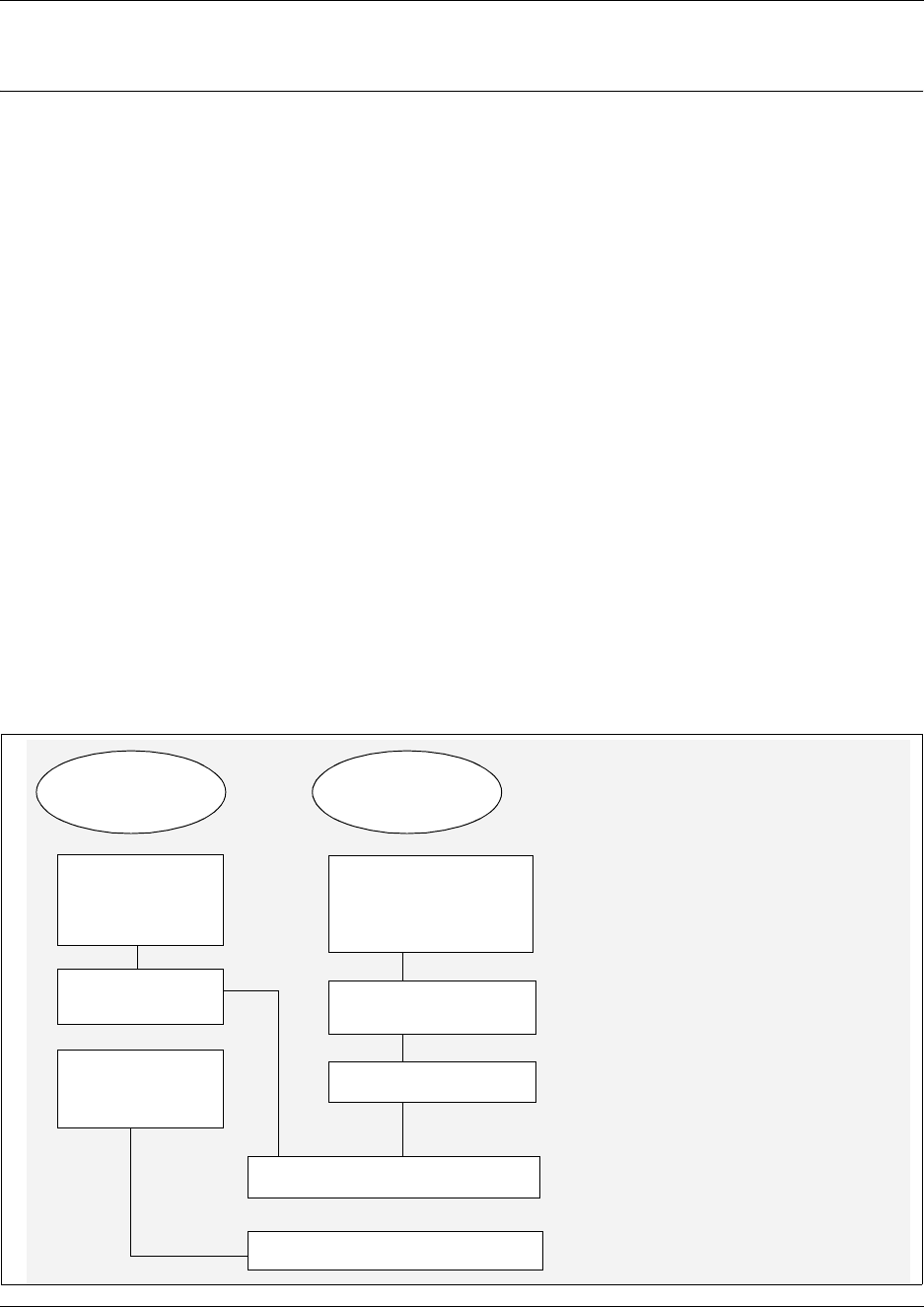
249
Installation and Maintenance Guide
Chapter 12
Install Companion or DECT Systems
This chapter describes the two radio-based systems that can be added to the Business
Communications Manager system to provide mobile communications.
Both systems require radio-equipped base stations connected to specific types of media bay
modules installed in the Business Communications Manager.
• The Companion requires a DSM module for the base stations to plug into. Refer to “The
Companion Wireless System” on page 249.
• DECT provides virtual BRI loops within the DECT module. Refer to “Install DECT systems”
on page 275.
The Companion Wireless System
Your Companion portable telephone allows you to leave your desk without missing important
telephone calls. The portable telephones can access most Business Communications Manager
business features such as call forward, call transfer, voice conference, and voice messaging using
feature codes.
Figure 160 provides an overview of the process for installing a Companion wireless system onto
the Business Communications Manager system.
Figure 160 Overview of installing a Companion system
DSM module
installed and
configured
Install remote power
interconnect (RPI)
Install external
antennas and
lightning protection, if
required
Install base stations
Restore system
to operation
Register Companion sets*
Business
Communications
Manager
Companion
equipment
Connect base stations to DSM
Configure DN
records for the
handsets
*In the United States,
you must enter a UTAM
keycode before you
register the handsets.

250 Chapter 12 Install Companion or DECT Systems
P0993133 03
Companion components
Business Communications Manager Companion has four main components:
Software - Companion software manages the telephone traffic between Companion base stations
and portable telephones. Base stations connect to Business Communications Manager in the same
way that Business Communications Manager sets do. You register the Companion portable
telephones on the system. They do not require any ports on the system. You can connect a
maximum of 60 portable telephones and a maximum of 32 base stations (32 cells) to the system.
Companion base stations — Position the base stations around the coverage area to send and
receive calls between the portable telephones and Business Communications Manager. Base
stations use digital radio technology and support handoff and roaming within the coverage area.
The coverage area can be a maximum of 160,000 square meters (1,700,000 square feet) when
using the maximum number of base stations.
Companion wireless handsets — Business Communications Manager supports the following
wireless handsets: Companion 3020, Companion C3050 Etiquette, Companion C3050 CT2Plus,
and Companion C3060.
The portable telephones used with your Business Communications Manager system are small,
lightweight units with complete digital performance to provide clear voice quality. Companion
portable telephones feature a three-line, 16-character, alphanumeric display.
Administration and Maintenance Tools — Programming of the Companion system is easily and
quickly done through the Business Communications Manager Unified Manager. You can assign
portable telephones to the system, check base station parameters, and enable and disable
registration through programming.
Companion Diagnostics Software allows you to run diagnostics on the wireless system. You run
the diagnostics using a personal computer located at the customer site or in a remote location.
For more information about programming Companion and running diagnostics, see the Business
Communications Manager 3.0, Programming Operations Guide.
Note: Companion wireless availability is region-specific. Refer to “Mobility Services by
Region” on page 303. This option also requires a software keycode for activation.
Note: If you choose a 3/5 channel split for your system, you cannot assign a module to
channel 7. This limits you to a maximum of 16 base stations, which can support a
maximum of 30 handsets.
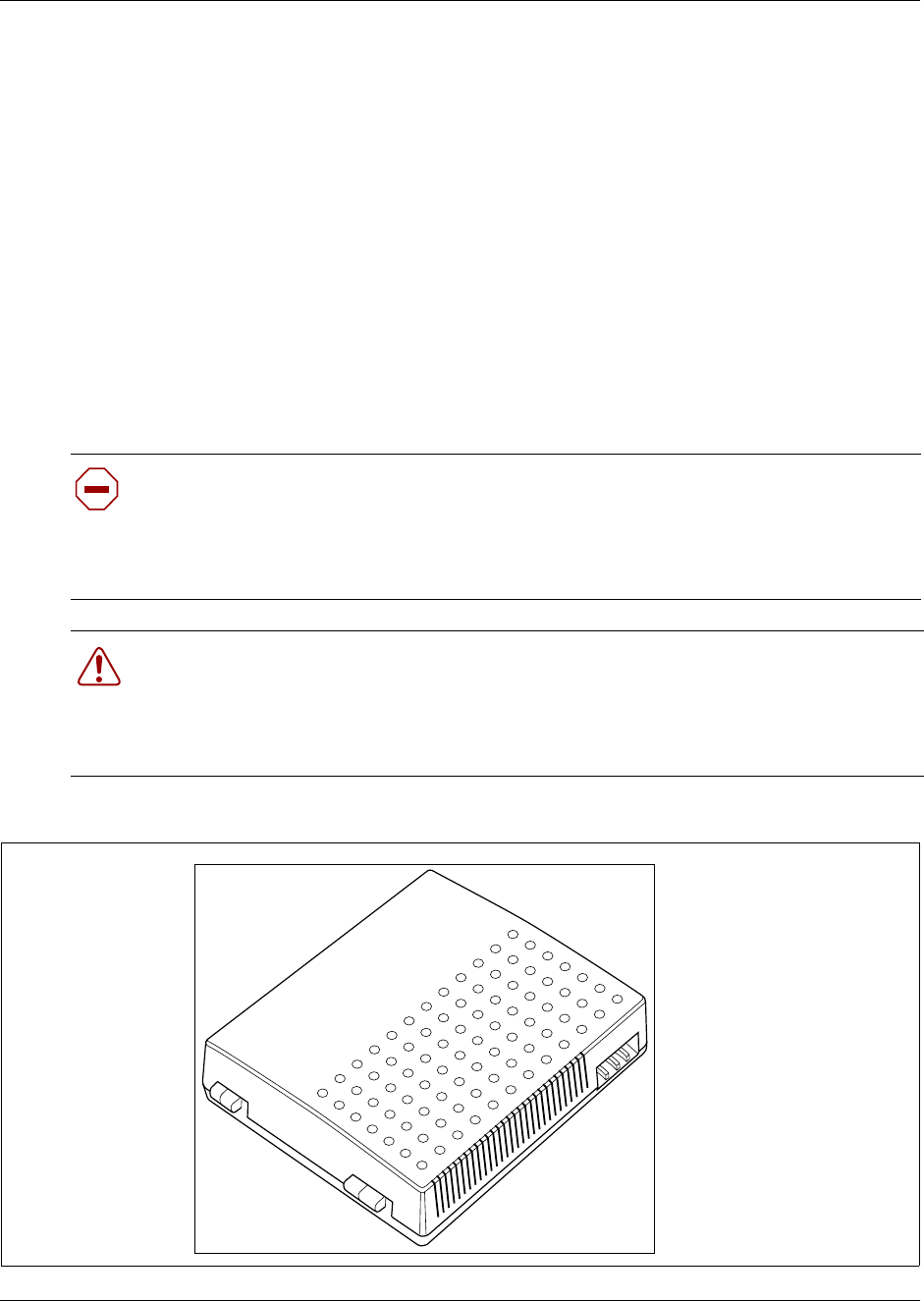
Chapter 12 Install Companion or DECT Systems 251
Installation and Maintenance Guide
Companion Hardware Installation
The Companion hardware must be in place and configured before you can use the handsets to
connect to the Business Communications Manager. This section describes how to install the
Companion hardware components.
The base station has the option of using internal or external antennas. For most installations, the
internal antenna will be used. If you need to install external antennas, refer to “Install an external
antenna and lightning surge protection” on page 265.
Install the base station remote power interconnect (RPI) unit
The remote power interconnect unit (RPI) provides remote power for base station support. Figure
161 shows a diagram of the RPI.
Figure 161 RPI unit
Caution: The RPI unit must have the DC backup power supplied by a UL listed universal
power supply (UPS).
The UPS must have an output voltage rating of 44 to 52 V DC, with a maximum fault
current limit of 6 A to protect the RPI output wiring. If these requirements are not met, it is
necessary to use class 1 wiring.
Warning: Install the RPI units inside a building.
The AC outlet powering the RPI must be installed near the equipment and must be easily
accessible.
The length of the RPI cord, from the outside surface of the unit to the plug, must be a
minimum of 1.3 m (4.5 ft) and a maximum of 4.6 m (15 ft).

252 Chapter 12 Install Companion or DECT Systems
P0993133 03
There are two versions of the RPI unit:
• The RPI-8 BIX UL supports a maximum of eight base stations.
• The RPI-16 BIX UL supports a maximum of 16 base stations.
Each RPI has a connection printed-circuit board and either one (RPI-8 BIX UL) or two (RPI-16
BIX UL) power supply units (PSUs). The maximum input power consumption of an RPI is 240 W.
If you use a UPS 48 V dc backup source, the maximum input power requirement of the RPI is
140 W.
Install a second PSU to the RPI-8 BIX UL to upgrade an RPI-8 BIX UL to an RPI-16 BIX UL.
If you distribute the RPIs around the site, the number and type of RPIs depend on where you place
and how you power the base stations.
Use Table 26 to determine how many base stations and how many PSUs you need for the number
of base stations:
Mount the RPI unit
Use the following guidelines to mount the RPI unit:
• Provide adequate ventilation to prevent overheating. Leave a clearance of a minimum of 125
mm (5 in.) around the RPI.
• To install two RPIs, one above the other, leave a clearance of a minimum of 300 mm (12 in.)
between them to provide acceptable ventilation and to prevent overheating.
• Install RPIs a minimum of 300 mm (12 in.) from the ceiling.
Table 26 RPI Requirements
Base stations RPI-16 and RPI-8 required PSUs required
1–8 1 RPI-8 1 PSU
9–16 1 RPI-16 2 PSUs
17–24 1 RPI-16 and 1 RPI-8 3 PSUs
25–32 2 RPI-16 4 PSUs
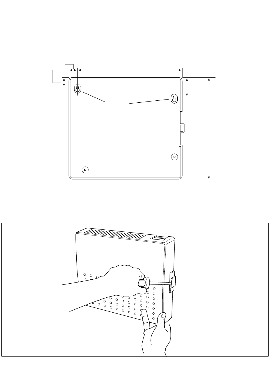
Chapter 12 Install Companion or DECT Systems 253
Installation and Maintenance Guide
Use this procedure to mount the RPI unit.
1Partially install two #10 50 mm (2 in.) screws using the dimensions shown in Figure 162.
Figure 162 RPI mounting holes
2Open the cover with a screwdriver. Push the screwdriver in, and then down, to release the latch
on the right side. Remove the cover by lifting it up. Refer to Figure 163.
Figure 163 Open the RPI cover
3Hang the RPI on the two screws. Tighten the screws.
325 mm
(13 in.)
25 mm
(1 in.)
50 mm
(2 in.)
300 mm
(12 in.)
Keyholes
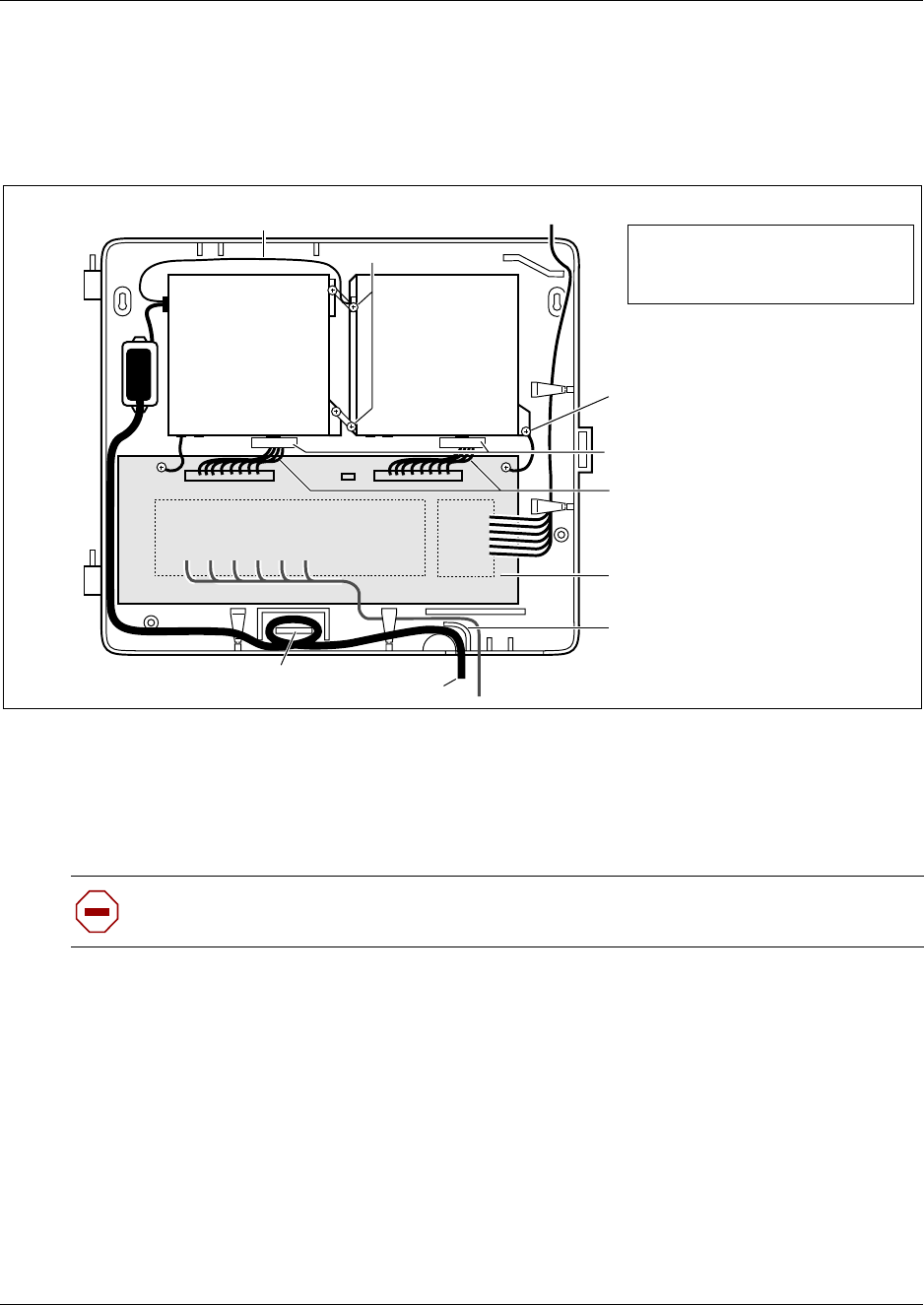
254 Chapter 12 Install Companion or DECT Systems
P0993133 03
4Install the remaining two screws.
5Feed the power cord through the bottom of the RPI and route it through the clip and around the
strain relief support. Figure 164 shows how to route the power cord.
Figure 164 RPI components
6Route the power cord to the input power socket just to the left of PSU 1.
7Connect the plug to the socket.
8Follow the appropriate wiring instructions in the wiring charts in section, “RPI wiring and
connections”.
9After the cable is wired correctly, connect the RPI power cord to the ac outlet.
10 Label each RPI.
11 This procedure is complete.
Caution: Do not apply power to the RPI until its installation and wiring are complete.
PSU 1 PSU 2
(if equipped)
Up to 16 outputs
(TCM + power)
Up to
16
inputs
(TCM) Connection board
Jumper lead to PSU 2
Power cord
Grounding strap
Power supply cabling
Strain relief support
Clip
Grounding plates
Ferrite rings
The RPI-8 has grounding straps
and plates fitted to allow an
upgrade to an RPI-16.
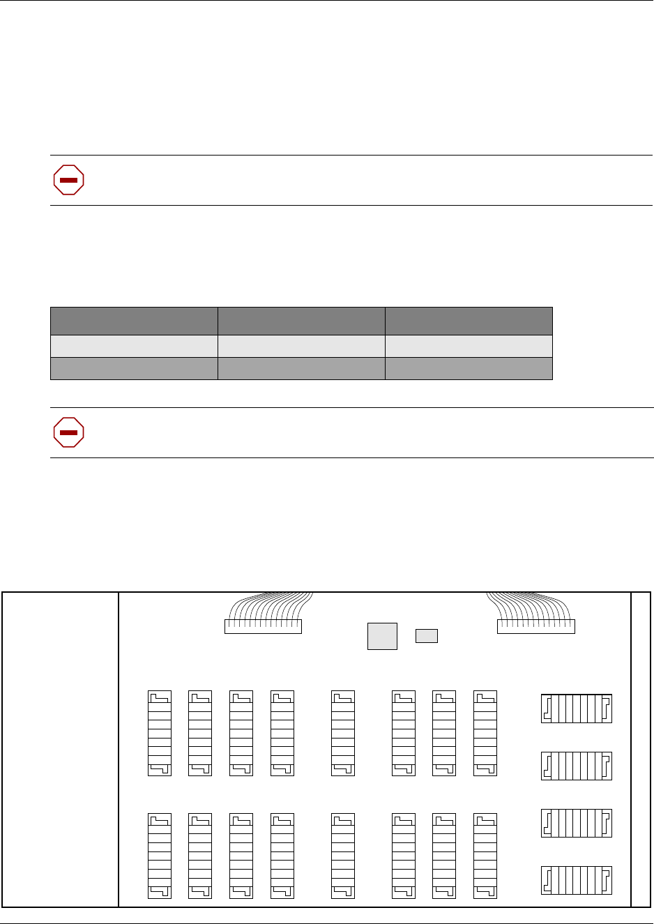
Chapter 12 Install Companion or DECT Systems 255
Installation and Maintenance Guide
RPI wiring and connections
The maximum two-way DC loop resistance for power pairs, including interconnections for each
base station, is 75 ohms. You need one or two power pairs between the RPI and the base station.
The number of power pairs depends on the wire size of the power pair and the distance between
the base station and the RPI.
The maximum cable distances allowed between the RPI and the base station depend on the size of
wire you use. Refer to Table 27.
Connect the RPI
Connect the power pairs to the correct connectors. Figure 165 shows the location of the input and
output connectors on the RPI connector printed-circuit board.
Figure 165 RPI connector printed-circuit board
Caution: Do not run unprotected power cables outdoors.
Table 27 Cable distances
Wire size Single pair Double pair
0.6 mm (22 AWG) 800 m (2,500 ft.) 1200 m (4,000 ft.)
0.5 mm (24 AWG) 500 m (1,500 ft.) 1000 m (3,000 ft.)
Caution: When you use two power pairs, connect both pairs with the same polarity.
OBIX1 OBIX2 OBIX3 OBIX4 OBIX9 OBIX10 OBIX11 OBIX12
OBIX5 OBIX6 OBIX7 OBIX8 OBIX13 OBIX14 OBIX15 OBIX16
IBIX1IBIX3IBIX2IBIX4
0B1X1 0B1X2 0B1X3 0B1X4 0B1X9 0B1X10 0B1X11 0B1X12
0B1X5 0B1X6 0B1X7 0B1X8 0B1X9 0B1X13 0B1X14 0B1X15
IBIX4 IBIX3 IBIX2 IBIX2
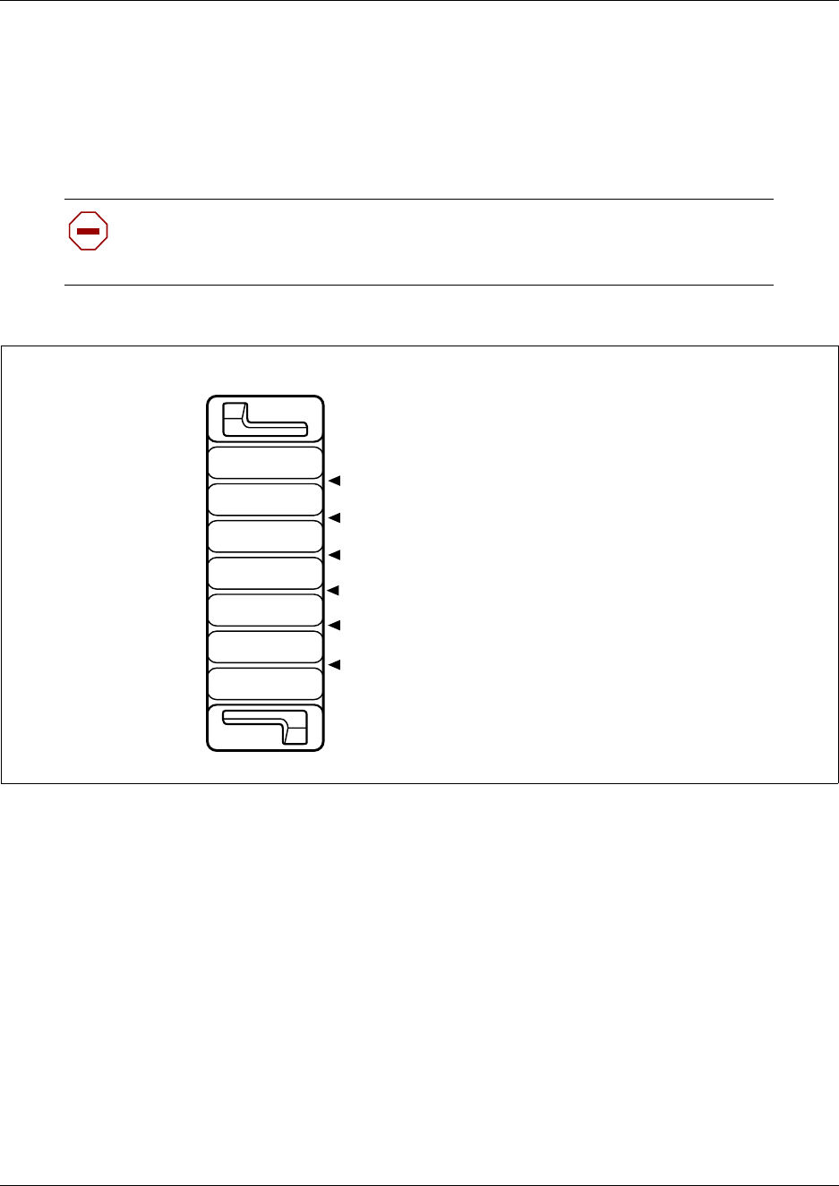
256 Chapter 12 Install Companion or DECT Systems
P0993133 03
RPI output connections
Feed the output pairs in through the bottom of the RPI and route the pairs to the output connectors.
Figure 166 shows how to route the output pairs. If you use one pair to power a base station,
connect the power pair to -PWR(1) and +PWR(1). If you use two pairs to power a base station,
connect one pair to -PWR(1) and +PWR(1), and the second pair to -PWR(2) and +PWR(2).
Figure 166 Output connector pinout
RPI input connections
Feed the TCM input pairs from the Business Communications Manager distribution frame through
the top of the RPI and route them to the input connectors (IBIX1 to IBIX4).
Figure 167 shows how to route the input pairs. The maximum number of input pairs in an RPI
installation is 16. Table 28 lists the pinout and signal references.
Caution: Ensure both pairs have the same polarity.
If you connect two power pairs with opposite polarities, you can damage the base
station and RPI.
OBIXn
-PWR(1)
TCM
TCM
+PWR(1)
-PWR(2)
+PWR(2)
OBIXn
-PWR(1)
-PWR(2)
TCM
TCM
+PWR(1)
+PWR(2)
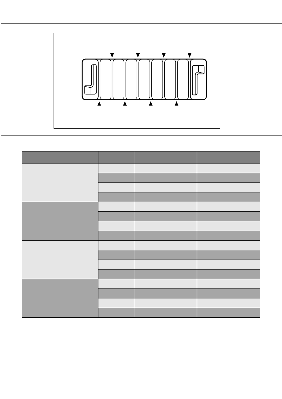
Chapter 12 Install Companion or DECT Systems 257
Installation and Maintenance Guide
Figure 167 Input connector pinout
Table 28 Input wiring
Connector Pin Signal Output connector
IBIX1 1, 2 TCM 1 OBIX1
3, 4 TCM 2 OBIX2
5, 6 TCM 3 OBIX3
7, 8 TCM 4 OBIX4
IBIX2 1, 2 TCM 5 OBIX5
3, 4 TCM 6 OBIX6
5, 6 TCM 7 OBIX7
7, 8 TCM 8 OBIX8
IBIX3 1, 2 TCM 9 OBIX9
3, 4 TCM 10 OBIX10
5, 6 TCM 11 OBIX11
7, 8 TCM 12 OBIX12
IBIX4 1, 2 TCM 13 OBIX13
3, 4 TCM 14 OBIX14
5, 6 TCM 15 OBIX15
7, 8 TCM 16 OBIX16
IBIXn
Pin 3 Pin 1
Pin 2Pin 4Pin 6Pin 8
Pin 5Pin 7
Pin 7
IBIXn
Pin 5 Pin 3 Pin 1
Pin 8 Pin 6 Pin 4 Pin 2

258 Chapter 12 Install Companion or DECT Systems
P0993133 03
RPI-8 BIX wiring chart
Table 29 lists the wiring chart for the RPI-8 BIX.
Table 29 RPI-8 BIX wiring chart
Pin RPI Connector printed-circuit board Label Wire color
26
OBIX1
BS1
-PWR White-Blue
1Blue-White
27 TCM White-Orange
2Orange-White
28 +PWR White-Green
3Green-White
29
OBIX2
BS2
-PWR White-Brown
4Brown-White
30 TCM White-Slate
5Slate-White
31 +PWR Red-Blue
6Blue-Red
32
OBIX3
BS3
-PWR Red-Orange
7Orange-Red
33 TCM Red-Green
8Green-Red
34 +PWR Red-Brown
9Brown-Red
35
OBIX4
BS4
-PWR Red-Slate
10 Slate-Red
36 TCM Black-Blue
11 Blue-Black
37 +PWR Black-Orange
12 Orange-Black
38
OBIX5
BS5
-PWR Black-Green
13 Green-Black
39 TCM Black-Brown
14 Brown-Black
40 +PWR Black-Slate
15 Slate-Black

Chapter 12 Install Companion or DECT Systems 259
Installation and Maintenance Guide
RPI-8 BIX wiring chart
Table 30 lists the wiring chart for the RPI-16 BIX.
41
OBIX6
BS6
-PWR Yellow-Blue
16 Blue-Yellow
42 TCM Yellow-Orange
17 Orange-Yellow
43 +PWR Yellow-Green
18 Green-Yellow
44
OBIX7
BS7
-PWR Yellow-Brown
19 Brown-Yellow
45 TCM Yellow-Slate
20 Slate-Yellow
46 +PWR Violet-Blue
21 Blue-Violet
47
OBIX8
BS8
-PWR Violet-Orange
22 Orange-Violet
48 TCM Violet-Green
23 Green-Violet
49 +PWR Violet-Brown
24 Brown-Violet
Table 30 RPI-16 BIX wiring chart
Pin RPI Connector printed-circuit board Label Wire color
26
OBIX9
BS9
-PWR White-Blue
1Blue-White
27 TCM White-Orange
2Orange-White
28 +PWR White-Green
3Green-White
29
OBIX10
BS10
-PWR White-Brown
4Brown-White
30 TCM White-Slate
5Slate-White
31 +PWR Red-Blue
6Blue-Red
Table 29 RPI-8 BIX wiring chart (Continued)
Pin RPI Connector printed-circuit board Label Wire color

260 Chapter 12 Install Companion or DECT Systems
P0993133 03
32
OBIX11
BS11
-PWR Red-Orange
7Orange-Red
33 TCM Red-Green
8Green-Red
34 +PWR Red-Brown
9Brown-Red
35
OBIX12
BS12
-PWR Red-Slate
10 Slate-Red
36 TCM Black-Blue
11 Blue-Black
37 +PWR Black-Orange
12 Orange-Black
38
OBIX13
BS13
-PWR Black-Green
13 Green-Black
39 TCM Black-Brown
14 Brown-Black
40 +PWR Black-Slate
15 Slate-Black
41
OBIX14
BS14
-PWR Yellow-Blue
16 Blue-Yellow
42 TCM Yellow-Orange
17 Orange-Yellow
43 +PWR Yellow-Green
18 Green-Yellow
44
OBIX15
BS15
-PWR Yellow-Brown
19 Brown-Yellow
45 TCM Yellow-Slate
20 Slate-Yellow
46 +PWR Violet-Blue
21 Blue-Violet
47
OBIX16
BS16
-PWR Violet-Orange
22 Orange-Violet
48 TCM Violet-Green
23 Green-Violet
49 +PWR Violet-Brown
24 Brown-Violet
Table 30 RPI-16 BIX wiring chart (Continued)
Pin RPI Connector printed-circuit board Label Wire color

Chapter 12 Install Companion or DECT Systems 261
Installation and Maintenance Guide
Install a Companion base station
Before you install wireless equipment, ensure that a site planner determines base station locations
and records the base station information in a provisioning record.
Before you install or move wireless equipment in the United States, check that you have approval
from UTAM Inc.
The United States FCC has appointed UTAM Inc. as the body responsible for coordinating and
verifying the installation or relocation of unlicensed, personal wireless communication devices. To
comply with UTAM Inc., the system uses keys and credits to control user capacity and to ensure
system location verification. You require these software keys and credits to activate Companion
services. You purchase these credits at the time you place the order.
Position the Companion base station
Avoid installing base stations on large concrete or marble columns because these columns affect
radio coverage. If possible, place the base station a minimum of 1 m (40 in.) from these types of
columns. Do not install a base station with the antenna housings near metal objects. Be careful not
to damage existing wiring or panels.
Do not position base stations in ducts, plenums, or hollow spaces used to transport environmental
air except where the duct, plenum or hollow space is created by a suspended ceiling having lay-in
panels. When you need more than one base station in a cell to meet traffic requirements, position
the base stations at the same cell center.
To place all base stations in the same cell center:
• for the USA, a minimum of 54 in. and a maximum of 9 ft. 9 in. distance between the center of
one base station to the center of another
• for Canada, a minimum of 9 cm and a maximum of 1.5 m distance from edge to edge
Position base stations away from office areas or areas with high portable telephone traffic. Table
31 on page 262 shows the minimum distance between office areas and base stations. Install the
base station on the ceiling or high on walls to maintain these minimum distances.
Caution: You must install all base stations within 1230 m (4000 ft., TCM wiring length)
of the Business Communications Manager system or base station module.
To optimize seamless hand off, the difference in TCM wiring length between neighboring
base stations must not exceed 300 m (1,000 ft.).
Warning: Never install base stations in rows.
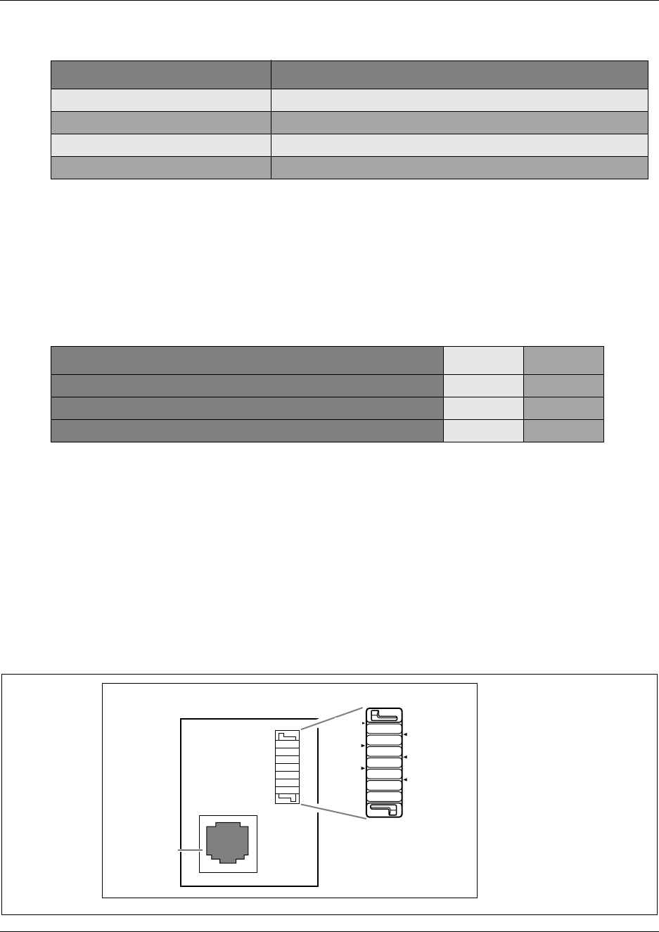
262 Chapter 12 Install Companion or DECT Systems
P0993133 03
Attach a Companion Base Station to a wall or ceiling
Install base stations on a wall or on a ceiling. When installing base stations on a wall, install them
with their covers at the bottom, as shown in Figure 169 on page 263. Allow for clearances around
the base station as indicated in Table 32.
Use this procedure to install a base station:
1Fasten the bracket into position using two #8 38-mm (1-1/2 in.) screws.
2Route the cable from the Business Communications Manager system through the top or
bottom opening.
3Wind any excess cable around the posts, then fasten the cable under the strain relief.
4Connect the wires to the BIX connector on the bracket termination board as shown in Figure
168.
Figure 168 Bracket termination board
Table 31 Minimum distance between office areas and base stations
Number of base stations in the cell Minimum distance between office areas and base stations
11 m (40 in.)
21.4 m (56 in.)
31.8 m (72 in.)
42 m (80 in.)
Table 32 Clearance for the base stations
Clearance conditions Canada USA
Clearance from all other objects 9 cm 3.5 in.
Vertical clearance from base station center to base station center 27 cm 54 in.
Horizontal clearance from base station center to base station center 41 cm 54 in.
-PWR(1) TCM
+PWR(1)
+PWR(2)
-PWR(2)
TCM
RJ11 jack
TCM
RJ11 jack
TCM
-PWR(2) +PWR(1)
+PWR(2)
-PWR(1)
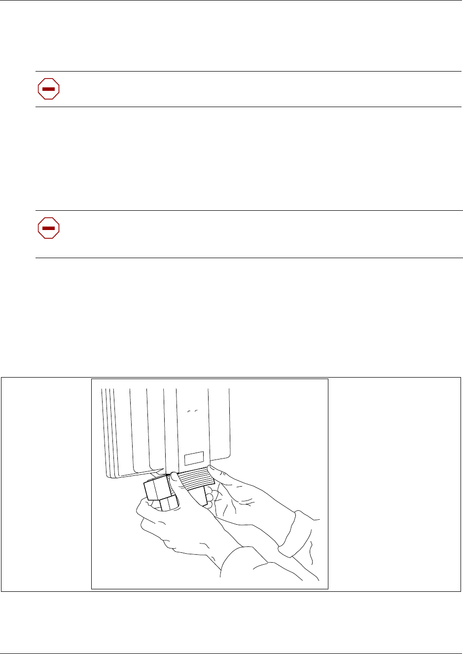
Chapter 12 Install Companion or DECT Systems 263
Installation and Maintenance Guide
The polarity of the TCM connections is not important. If you connect the two power pairs to
the bracket terminal board of the base station, you must connect the power pairs with the same
polarity.
5Install the base station on the bracket. Snap it into position.
6Connect the power RJ-11 jumper lead to the RJ-11 jacks on the termination board and the base
station.
7For plug top power supplies only, connect the power supply connector to the base station
power connector. Make sure the base station uses a class 2 plug top power source only.
8In the space provided on the label attached to the lower right corner of the mounting bracket,
record the port number used.
Include the marking information for all of the base stations on the completed installation floor
plans.
9Slide the cover on the bracket, using the guide to position it correctly. Refer to Figure 169.
Figure 169 Slide the cover on bracket
10 Snap the cover into place.
11 This procedure is complete.
Caution: Ensure that the RPI is off before connecting power pairs to the base station.
Caution: If you insert the power supply connector in the wrong direction, you can
damage the plug top power supply and the base stations.
Position the power supply connector in the correct direction and push it into place.
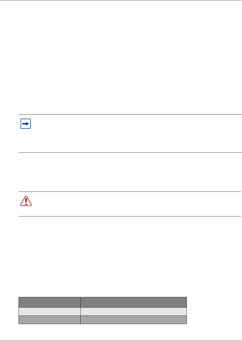
264 Chapter 12 Install Companion or DECT Systems
P0993133 03
Companion set registration
To use Companion portable telephones, you must first install radio base stations to transmit and
receive radio signals to and from the portable telephones. See “Install a companion base station”
on page 261.
You use a different method to install portable telephones than desktop telephones. There are no
direct connections between the portable telephones and the system. Do the following:
• Install the batteries and battery charging units for each portable, using the instructions that
come with the portable.
• Enter the software keys for Companion in the Business Communications Manager Unified
Manager under Software keys
• Register every Companion portable for use with the system.
System restart
Use this procedure to perform a system restart.
If you added a base station that requires a software update, the system begins downloading the
software to the base station. The display shows BS-1 Dload Start.
1Press CLEAR to clear the message. When the base station software finishes downloading, the
BS-1 Dload Done appears.
2Press CLEAR to clear the message. Some base stations do not power up at the same time, and
this message repeats at the beginning of each download.
In the United States, the display shows one of the messages listed in Table 33 after restarting:
3This procedure is complete.
Note: You must register a portable telephone before you can use it. By default,
Companion portable telephones are not assigned extension numbers. The range of portable
extensions available for wireless registration is 061 to 118. For more information about
registering and programming Companion portables, see the Business Communications
Manager 3.0, Programming Operations Guide.
Warning: A loss of unlicensed transition and management for microwave (UTAM)
information occurs when upgrading US Business Communications Manager systems.
You need UTAM Recovery Codes.
Table 33 UTAM messages
If display shows See
UTAM code req’d System logical identifier (LID) information
UTAM test failed See alarm codes in the Windows NT event log.
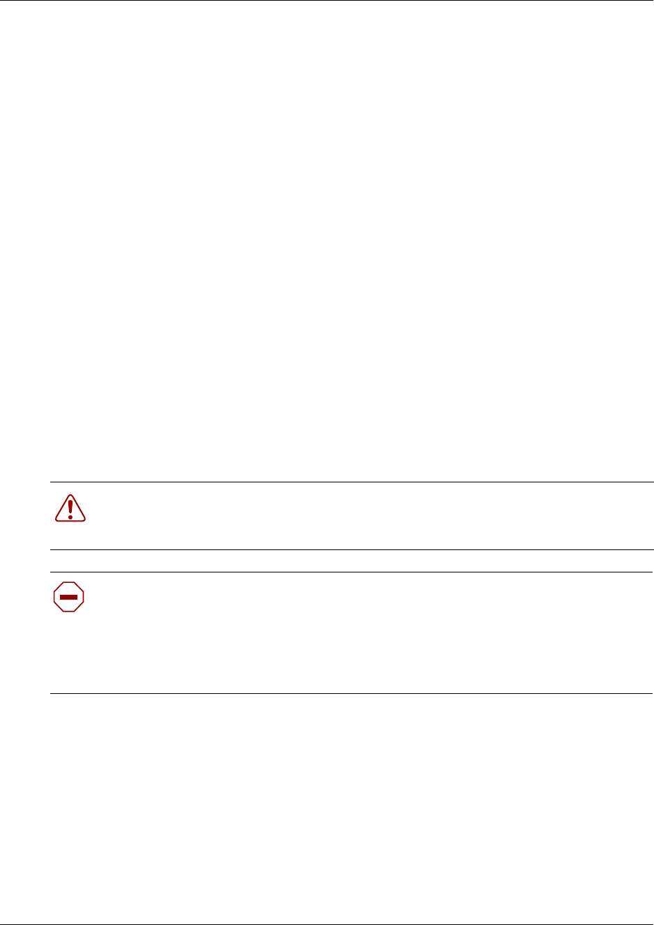
Chapter 12 Install Companion or DECT Systems 265
Installation and Maintenance Guide
Install an external antenna and lightning surge protection
You can use external antennas to provide a broad range for your Companion system. Ensure that
any external installations comply with local regulations and include lightning surge protection.
Read before you install equipment
• Install the antenna vertically. For more information, refer to Figure 170 on page 266.
• Use #8, 12 mm to 50 mm (1/2 in. to 2 in.) screws to install the antenna bracket and lightning
surge protector bracket to the wall.
• Ensure the antenna is clear of any adjacent obstruction or metal objects. If you use more than
one external antenna at a cell center, separate the antennas at by least 1 m (40 in.) to avoid
radio interference problems.
• When running the coaxial cable inside or outside, be careful not to damage the cable. Cable
damage affects performance. The minimum recommended bending radius is 200 mm (8 in.).
• The coaxial cable length must not exceed 10 m (33 ft).
• Use RG-58AU coaxial cables to connect the antennas to the base stations.
• You can attach a proprietary extension cable between the lightning surge protector and the
antenna or between the lightning surge protector and the base station. Make sure you keep the
total cable length as short as possible and use only the recommended extension cable when
necessary.
• Install a lightning surge protector for each external antenna.
Antenna installation (United States of America)
The following points cover special information about installations in the United States of America.
• The outdoor antenna connectors on the base station are special proprietary BNC connectors.
• Antennas are supplied with cables attached and terminated with special proprietary BNC plugs
to join with the connector on the base station.
• Cables are not supplied with outdoor antennas.
Warning: FCC requirements.
In the United States, the FCC requires that you connect only approved antennas to
Companion base stations.
Caution: Do not install the outdoor antenna or the lightning surge protector during an
electrical storm.
Always turn off the base station power before connecting the coaxial cable of an outdoor
antenna.
Always install the lightning surge protector at the cable entry point into the building.
Connect the lightning surge protector to ground before you connect the coaxial cable.
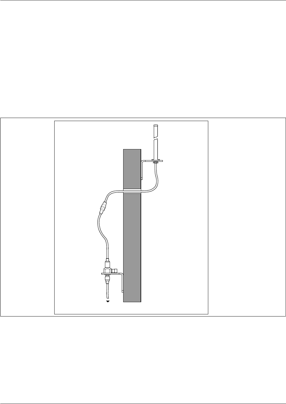
266 Chapter 12 Install Companion or DECT Systems
P0993133 03
Install an outdoor antenna (USA)
Use the procedure in this section to install an outdoor antenna. Perform the following before you
install an outdoor antenna:
• Locate the antenna on the external wall of the building.
• Keep the outdoor antenna as close as possible to the base station connected to it. The base
station must always be inside the building. The recommended installation height for the
antenna is 13 to 16 ft. above ground.
• Always install a lightning surge protector between an outdoor antenna and a base station.
Refer to Figure 170.
Figure 170 Installed antenna and lightning surge protectors (USA)
1Make a hole for the coaxial cable.
2Install conduit for the antenna cable according to local building and wiring codes.
3Screw the antenna bracket to the wall so that the antenna is vertical on the exterior wall of the
building.
4Loosen the nut on the antenna.
5Slide the antenna into the slot of the bracket and tighten the nut. Refer to Figure 171.
Wall
Back to back
proprietary
BNC connectors
Lightning surge arrestor
with mounting bracket
to Base Station or proprietary extension cable
Mounting bracket
Antenna
Antenna
Mounting
bracket
Wall
Back to back
proprietary BNC
connectors
Lightning surge
arrestor with
mounting
bracket
to base station or proprietary extension cable
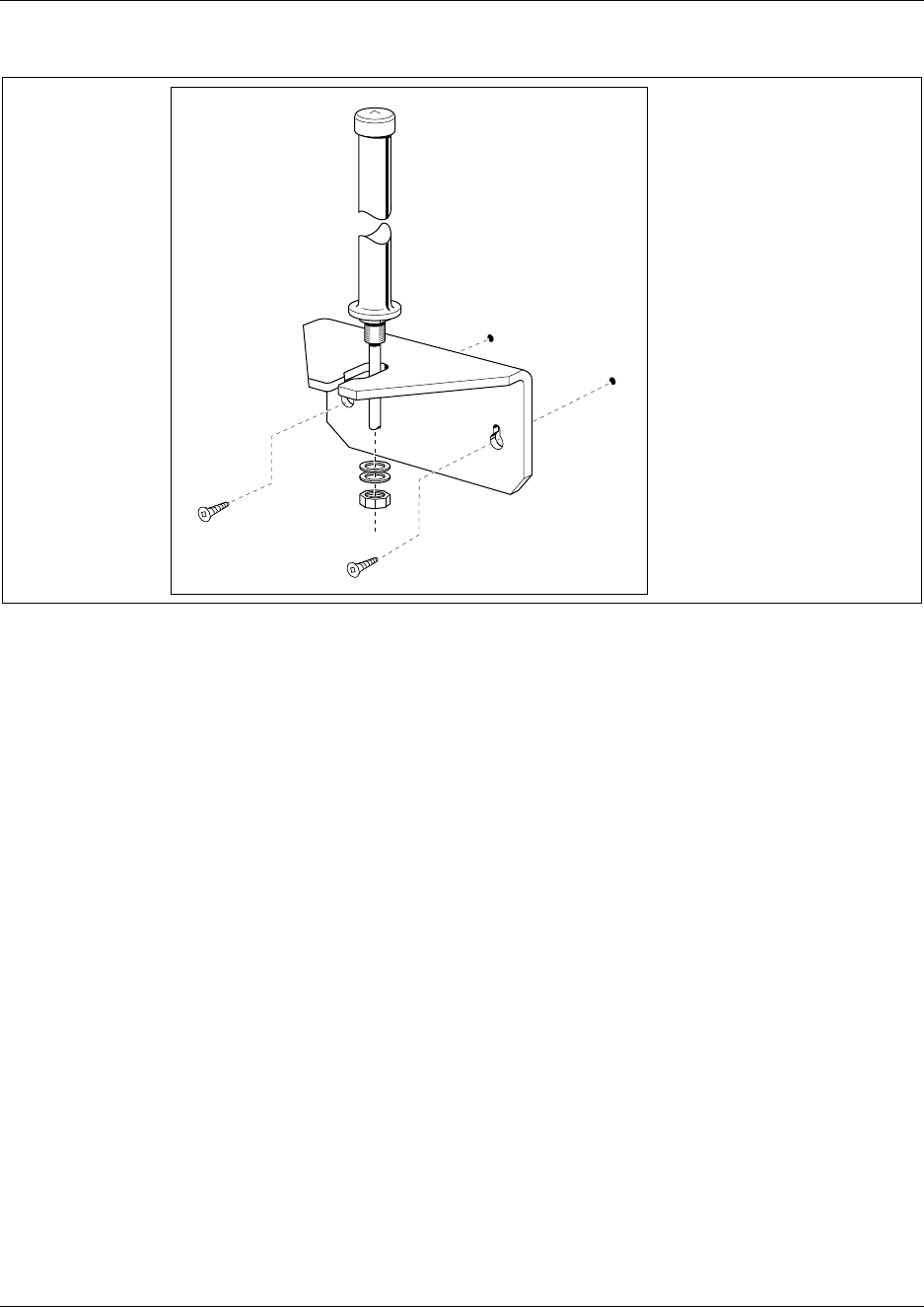
Chapter 12 Install Companion or DECT Systems 267
Installation and Maintenance Guide
Figure 171 Antenna with antenna bracket (USA)
6Feed the coaxial cable through the wall to the lightning surge protector on the interior wall.
7This procedure is complete.
Install a lightning surge protector (USA)
Use the procedure in this section to install the lightning surge protector. The surge protector
prevents damage to the Companion components due to electrical surges caused by lighting.
1Install the lightning surge protector on the interior wall as close as possible to the entry point
of the coaxial cable from the outdoor antenna.
Before you connect the ground lead to the lightning surge protector, attach the ground lead to
an approved ground. Refer to the Wiring information tips box on the next page.
2Route and connect the coaxial cable from the outdoor antenna to the lightning surge protector.
3Route and connect the coaxial cable from the lightning surge protector to the appropriate base
station connector. Refer to Figure 172 on page 268.
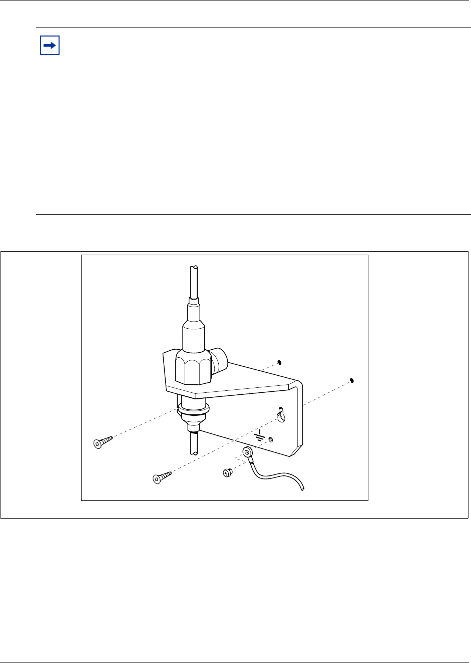
268 Chapter 12 Install Companion or DECT Systems
P0993133 03
Figure 172 Lightning surge protector and bracket (USA)
4This procedure is complete.
Tip: Wiring information
The recommended wire gauge is 6 AWG.
Connect the ground lead to the building ground. Do not connect to a ground rod or series of
ground rods.
If you cannot connect the ground lead to the building ground, connect the ground lead to
the metal frame of the building. The connection must be no more than six to 10 ft.
You can connect the ground lead to the 120 V ac conduit, which is connected to the
building ground. However, using the ac conduit is not the preferred method of installation.
The connector between the antenna and the lightning surge protector and between the
lightning surge protector and the base station is a proprietary BNC connector. You must
align the BNC connectors before you can make the connection.

Chapter 12 Install Companion or DECT Systems 269
Installation and Maintenance Guide
Install an antenna (Canada)
There are three types of external antennas available in Canada:
• indoor directional antenna
• indoor omnidirectional antenna
• outdoor omnidirectional antenna
Each type of installation requires a specific installation technique. As well, you must install a
lightning surge protector for every outdoor antenna installed.
Outdoor requirements
Before you install the antenna, ensure that your plan meets the following requirements:
• If you are installing an outdoor antenna on a metal surface greater than 18 cm (7 in.) in
diameter, position the antenna perpendicular to the surface.
• When running the coaxial cable inside or outside, be careful not to damage the cable, which
affects its performance. The minimum recommended bending radius is 20 mm (0.8 in.).
• Always ensure that the antenna is clear of any adjacent obstruction or metal objects. If you use
more than one outdoor antenna at a cell center, separate the antennas at by least 0.5 m (20 in.)
to avoid radio interference problems.
• Use RG-58/U coaxial cables to connect the antennas to the base stations.
Caution: Use only passive antennas to connect to the Companion base stations.
The coaxial cable you use to connect the external antenna to a Companion base
station must have an impedance of 50 ohms.
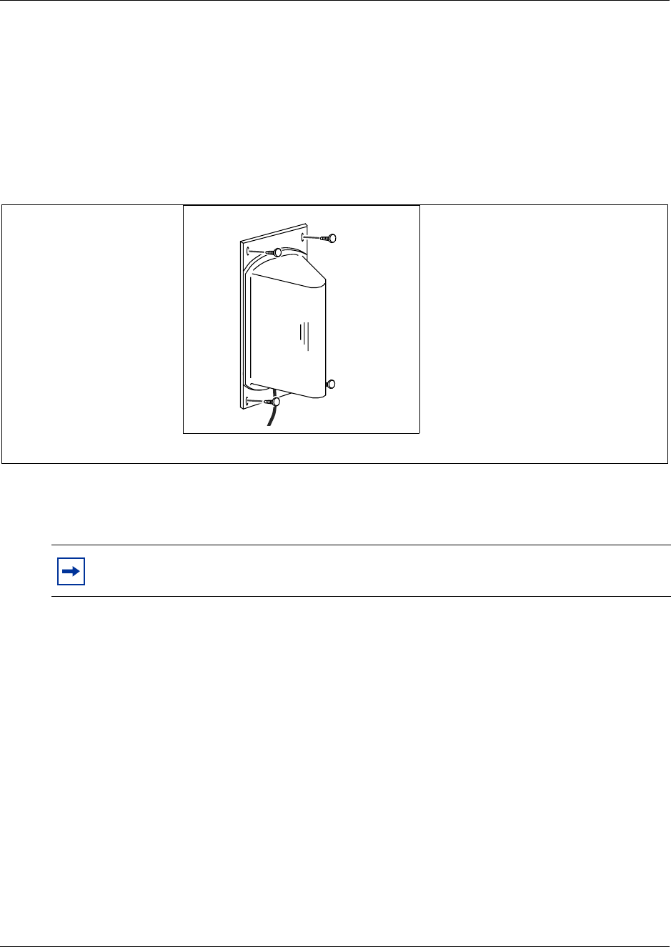
270 Chapter 12 Install Companion or DECT Systems
P0993133 03
Installing an Indoor Directional Antenna
The indoor directional antenna has a backplate that allows for easy installation on a wall. The
antenna is installed half way between the floor and the ceiling.
For some applications (for example, a stairwell), you can install the antenna on the ceiling.
1Use four screws to install the antenna. Refer to Figure 173.
Figure 173 Indoor directional external antenna (Canada)
2Fasten the cable to the mounting surface to prevent stress on the coaxial cable.
3Connect the antenna to the appropriate base station radio.
4This procedure is complete.
Note: The coaxial cable length must not exceed 10 m (33 ft.).
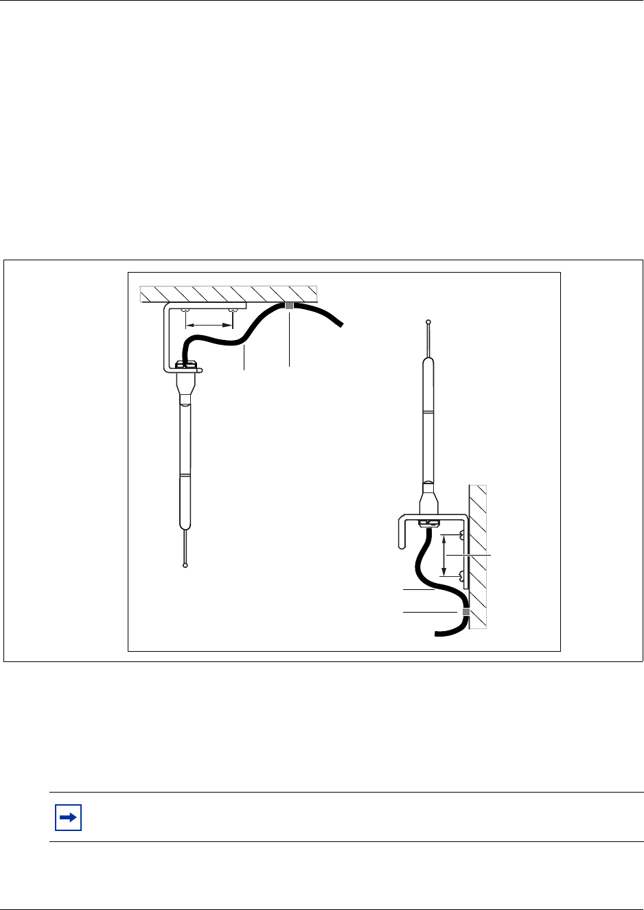
Chapter 12 Install Companion or DECT Systems 271
Installation and Maintenance Guide
Install an indoor omnidirectional antenna (Canada)
Use the procedure in this section to install an indoor, omnidirectional antenna (Canada only). Use
the following guidelines to install an indoor omnidirectional antenna:
• Use the bracket supplied to install the antenna on a wall or ceiling. This bracket provides the
necessary clearance between the floor or wall and the antenna.
• Mount the bracket so that the external antenna is vertical. The recommended installation
position on a wall is halfway between the floor and the ceiling.
Figure 174 shows the two methods of installing the indoor omnidirectional external antenna.
Figure 174 Indoor omnidirectional external antenna (Canada)
1Insert the antenna in the bracket so that the antenna is vertical.
2Use two screws to install the bracket to the wall or ceiling.
3Clamp the cable to the mounting surface to prevent cable stress on the coaxial cable.
4Connect the external antenna to the appropriate base station.
5This procedure is complete.
Note: The length of the coaxial cable must not exceed 10 m (33 ft.).
30 mm
Ceiling mount
installation
Wall mount
installation
30 mm
Cable
clamp
Cable
clamp
Co-axial
cable
Co-axial
cable
30 mm
30 mm
Co-axial
cable Cable
clamp
Ceiling mount installation
Co-axial cable
Cable clamp
Wall mount installation
272 Chapter 12 Install Companion or DECT Systems
P0993133 03
Install an outdoor omnidirectional antenna (Canada)
Use the procedure in this section to install an outdoor, omnidirectional antenna (Canada only). Use
the following guidelines to install an outdoor omnidirectional antenna:
• Locate the antenna on the external wall of the building.
• Keep the outdoor omnidirectional external antenna as close as possible to the base station. The
base station itself must always be located inside the building.
• The recommended installation height is 4 m (13 ft) to 5 m (16.5 ft) above ground level.
• Always install a surge protector between an outdoor omnidirectional external antenna and a
base station.
Note: You must install the antenna on a vertical surface.
Note: The connector on the outdoor omnidirectional external antenna is a TNC female
connector. To connect the antenna, you need an adapter to connect the TNC connector to
the BNC coaxial cables or a coaxial cable with a TNC male connector on one end and
BNC male connector on the other end.
Caution: Fit lightning protection to the antenna if appropriate.
See “Install a lightning surge protector (Canada)” on page 274 for more information.
Important points to remember:
• Do not install the external antenna or the lightning surge protector during an electrical
storm.
• Always turn off the base station power before connecting the coaxial cable of an
outdoor antenna.
• Always install the antenna at the cable entry point into the building.
• Connect the lightning surge protector to ground before connecting the coaxial cable.
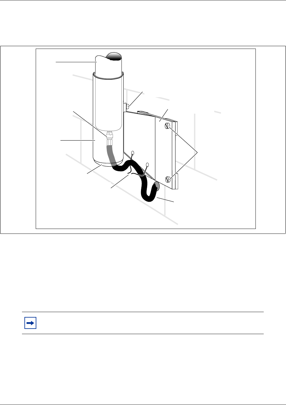
Chapter 12 Install Companion or DECT Systems 273
Installation and Maintenance Guide
1Screw the antenna mounting plate vertically to the exterior wall of the building with lag bolts
or other appropriate hardware. Figure 175 shows how to fasten the mounting plate.
Figure 175 Install the outdoor omnidirectional external antenna (Canada)
2Feed one end of the coaxial cable up through the bottom of the antenna cover and attach the
BNC connector to the base of the mast.
3Slide the mast down into the cover until it fits.
4Rotate the mast until the threaded hole in the base of the mast aligns with the set screw hole in
the cover. Tighten the set screw.
5Route the coaxial cable along the bottom edge of the plate between the cover and the wall
plate.
6Tie the cable to the mounting plate.
7Insert the plastic plug into the base of the cover to keep moisture out.
8Feed the coaxial cable through the wall to the surge protector on the interior wall.
9This procedure is complete.
Note: The total length of the coaxial cables from the outdoor antenna to the base
station must not exceed 10 m (33 ft.).
Plastic plug
Connector
at the base of
the mast
Shroud
Mast
Co-axial cable to
surge protector on
interior wall
Set screw
Cable ties
Exterior wall
mounting plate
Lag bolts or other
appropriate mounting
hardware
Mast
Set screw
Exterior wall
mounting plate
Lag bolts (or
appropriate
mounting hardware
Connector
at the base
of the mast
Shroud
Plastic plug
Cable ties
Co-axial cable to
surge protector
on interior wall
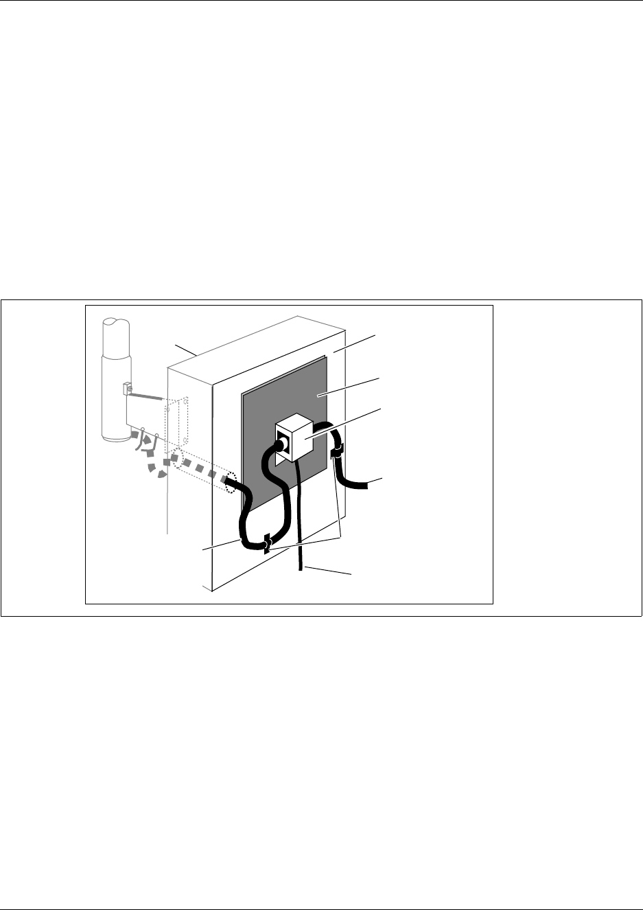
274 Chapter 12 Install Companion or DECT Systems
P0993133 03
Install a lightning surge protector (Canada)
Use the procedure in this section to install a lightning surge protector (Canada only).
Install the lightning surge protector for the outdoor omnidirectional external antenna to protect it
from electrical surges. The recommended lightning surge protector is part number A0382082.
Refer to the installation instructions from the manufacturer for more details on its installation. To
install a lightning surge protector, follow these steps:
1Install the surge protector on the interior wall as close as possible to the entry point of the
coaxial cable from the outdoor antenna.
Figure 176 shows where to locate the surge protector. Follow the installation instructions
provided with the surge protector.
Figure 176 Install the lightning surge protector (Canada)
2Attach the ground lead to an approved ground, before you connect the ground lead to the surge
protector.
The recommended wire gauge is 6 AWG (4 mm). Connect the ground lead to the building
ground. Do not connect to a ground rod or series of ground rods. If you cannot connect the
ground lead to the building ground, connect the ground lead to the metal frame of the building.
The connection must be no more than 2 m (6.5 ft.) to 3 m (10 ft.) long.
You can connect the ground lead to the 120 V ac conduit (which is connected to the building
ground). However, Nortel Networks does not recommend using the 120 V ac conduit.
3Route and connect the coaxial cable from the outdoor antenna to the surge protector.
Exterior
Wall
Interior
Wall
Copper plates
Surge protector
Co-axial cable to
Base Station
Low impedance
ground lead
Cable clamps
Co-axial cable
to outdoor
external antenna
Exterior wall Interior wall
Copper plates
Surge protector
Co-axial cable
to base station
Cable clamps
Low impedance
ground lead
Co-axial cable to
outdoor external
antenna
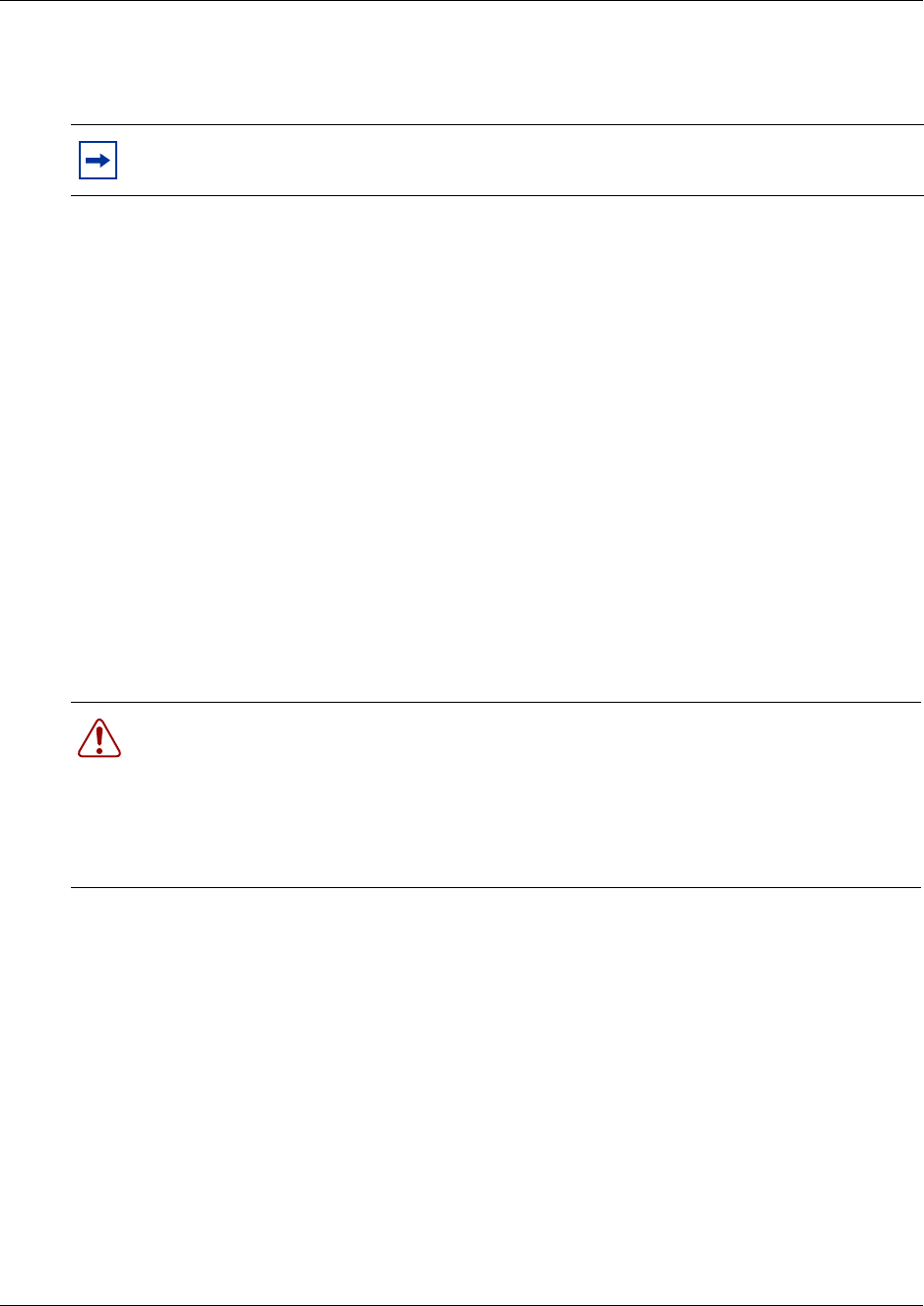
Chapter 12 Install Companion or DECT Systems 275
Installation and Maintenance Guide
4Route and connect the coaxial cable from the surge protector to the appropriate base station
BNC connector.
5This procedure is complete.
Install DECT Systems
The DECT system requires a DECT media bay module to allow communication between the
DECT handsets and the Business Communications Manager. The module installs in the Business
Communications Manager base unit or expansion unit. A maximum of eight base stations, which
are distributed throughout the transmission area, are connected to the module. After this step is
complete, the handsets are subscribed to the Business Communications Manager system.
For detailed installation refer to the Business Communications Manager 3.0 DECT Installation
and Maintenance Guide.
Each jack on the DECT module corresponds to an internal port on the DECT module. These
numbers are used to access the base stations when you disable them to turn mobile recording on
when you subscribe new handsets,.
Note: The total length of the coaxial cables from the outdoor antenna to the base station
must not exceed 10 m (33 ft.).
Warning: Plug each base station in sequentially. Ensure that each base station starts to
perform the startup sequence before plugging in the next base station. You can check base
station states through the DECT module interface.
Warning: For detailed information, refer to the DECT Installation and Maintenance
Guide. Figure 177 demonstrates these connections.
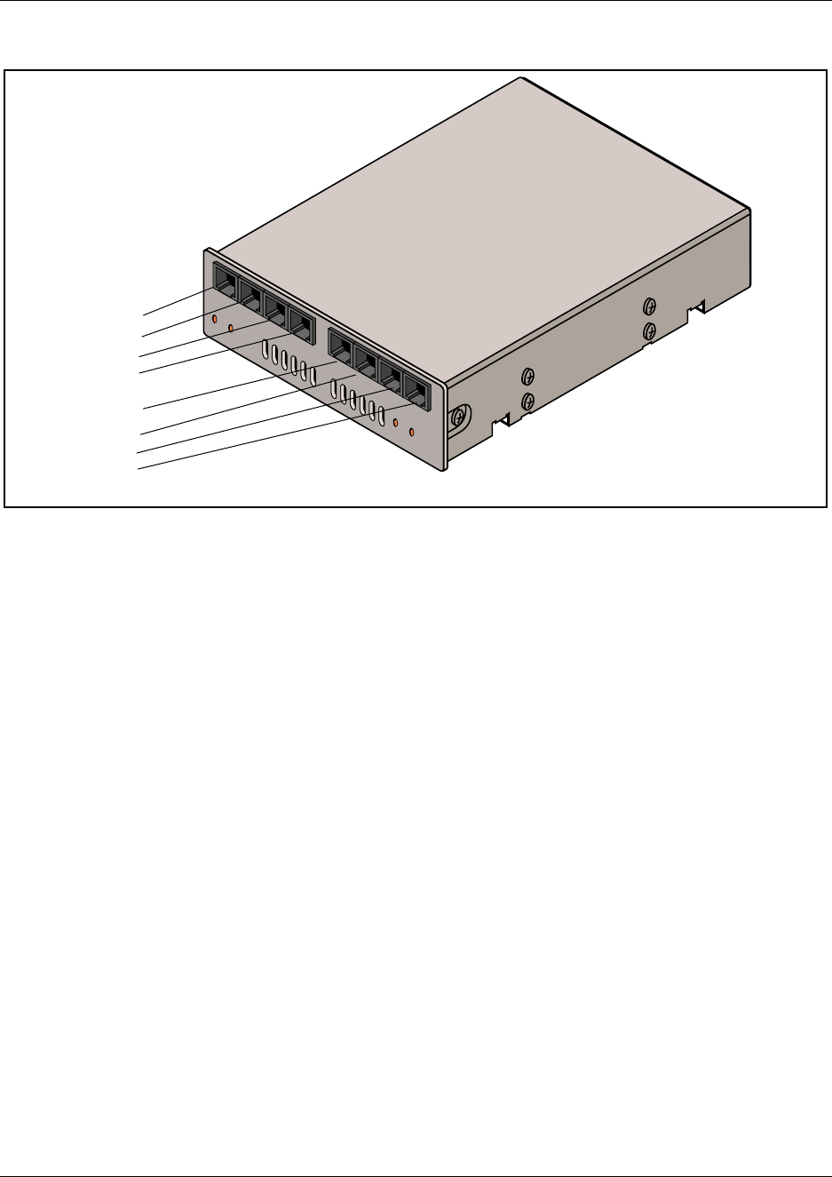
276 Chapter 12 Install Companion or DECT Systems
P0993133 03
Figure 177 R451 connectors on the DECT media bay module
7-3
7-2
7-1
7-0
6-3
6-2
6-1
6-0

277
Installation and Maintenance Guide
Chapter 13
Install Analog Terminal Adapters
This chapter provides installation instructions for the Analog Terminal Adapter 2 (ATA 2).
The Analog Terminal Adapter 2 (Business Communications Manager ATA 2) connects a standard
analog voice device or data communication device to the Business Communications Manager
system. Examples of analog voice devices are single-line telephones or answering machines.
Examples of data communication devices are modems and fax machines.
The Business Communications Manager ATA 2 provides on-premise service only (unexposed
plant only).
Before Installation
Before you attempt to install an ATA 2 device, ensure that your system and environment meet the
requirements listed in this section.
Environmental requirements
Check the following environment requirements for the Business Communications Manager ATA
2:
Operating requirements
The following are requirements for operating other analog or data communication devices:
Line voltage (120 V) 102 – 132 V ac
Line voltage (230 V) 207 – 253 V ac
Temperature 0 – 50°C (32 – 122°F)
Relative humidity 5% – 95% non-condensing
Bridge taps Not allowed between the Business Communications Manager system
loading coils and Business Communications Manager ATA 2
Ringing signal (North America):
Frequency Voltage:
20 Hz ± 1 Hz
80 V rms ± 10%
Ringing signal (Europe):
Frequency voltage:
25 Hz ± 1 Hz
75 V rms ± 10%
Ringer equivalence number 3
Battery feed voltage - 48 V dc ± 10%
Loop current 20 mA minimum
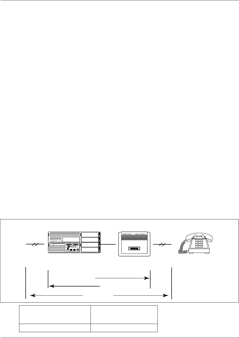
278 Chapter 13 Install Analog Terminal Adapters
P0993133 03
Analog transmission parameters
(North American systems only)
The following are the required analog parameters for an ATA2:
The maximum loss for Business Communications Manager ATA 2 to Central Office (CO)
configuration, shown in Figure 178, must not exceed 10 dB.
Figure 178 Insertion Loss from the CO to the single-line telephone
FIC code OL13ABC
Business Communications Manager ATA 2 to
Business Communications Manager system
loop resistance (cable only)
135 ohms maximum (for example: 800 m of
0.5 mm wire or 2,600 ft. of 24 AWG wire)
Analog loop resistance on terminal side for
voice applications (cable only) 1,300 ohms maximum (for example: 4,600 m of
0.4 mm wire or 15,000 ft. of 26 AWG wire)
Analog loop resistance on terminal for data
applications (cable only) 200 ohms maximum (for example: 730 m of
0.4 mm wire side or 2,400 ft. of 26 AWG wire)
Input impedance at tip and ring 600 ohms
Return loss > 20 dB for 200 to 3,400 Hz (when Network terminated
with 600 ohms)
Insertion loss on an internal call Business Communications Manager ATA 2 to Business
Communications Manager system loss 3.0 dB ± 0.5 dB
Insertion loss on an external call Business Communications Manager ATA 2 to Business
Communications Manager system loss 2.2 dB ± 1.0 dB
Business Communications Manager system to Business
Communications Manager ATA 2 loss 0.5 dB ± 1.0 dB
Longitudinal balance to ground 50 dB
60 to 4,000 Hz
With IEEE 455-1976 test
Overload level 3 dB
Single-line telephone
ATA 2
Business Communications Manager
Business Communications Manager to ATA 2
ATA 2 to Business Communications Manager
10 dB Max
Cable loss
Central Office
cable loss
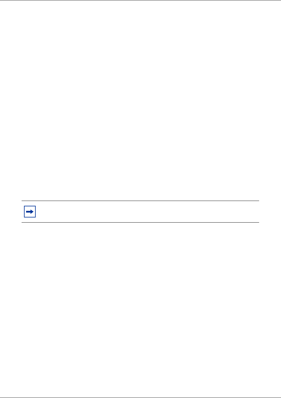
Chapter 13 Install Analog Terminal Adapters 279
Installation and Maintenance Guide
Measure insertion loss
Measure the total insertion loss between the CO and voice messaging device by using standard dial
up test lines with a transmission test set. For example, Hewlett-Packard 4935A Transmission Test
Set.
Measure insertion loss between the Central office and analog device
Use this procedure to measure the insertion loss from the CO to the voice messaging device:
1Establish a connection to the 1 mW, 1 kHz, CO service line with a single-line telephone
attached to the Business Communications Manager ATA 2.
2Ensure that the analog port terminates correctly in 600 ohms:
aReplace the single-line telephone with the test set
bUse RECEIVE/600 OHM/HOLD mode on the test set
3Ensure that the test set connects in parallel to the service line before removing the single-line
telephone or the line drops.
4Remove the single-line telephone.
5Measure the 1 kHz tone at the far end of the analog port, which is where the analog loop ends
and where the voice messaging device connects.)
6This procedure is complete.
Measure insertion loss from the analog device to Central Office
Use this procedure to measure the insertion loss from the voice messaging device to the CO:
1Establish a connection to a silent termination on the CO service line with a single-line
telephone attached to the Business Communications Manager ATA 2.
2Make sure the analog port terminates correctly in 600 ohms by:
• replacing the single-line telephone with the test set
•using
TRANSMIT/600 OHM/HOLD mode on the test set
3Make sure the test set connects in parallel to the service line before removing the single-line
telephone or the line drops.
4Remove the single-line telephone.
Note: The tone must be greater than - 10 dB (for example: - 9 dB is acceptable).
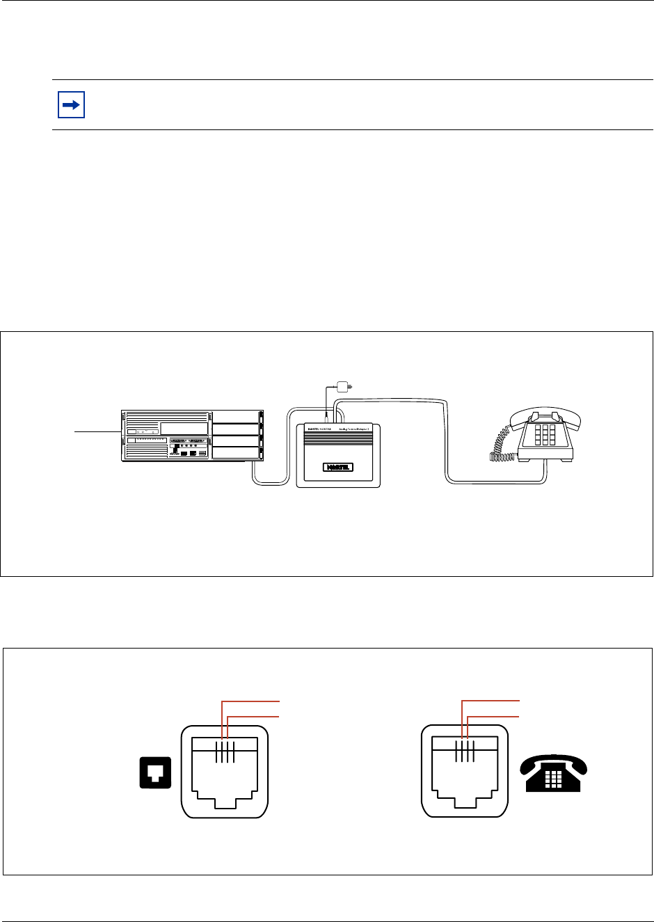
280 Chapter 13 Install Analog Terminal Adapters
P0993133 03
5Introduce a 1 kHz tone into the analog line at - 10 dBm, and measure the level at the CO
exchange.
6This procedure is complete.
Connect the Business Communications Manager ATA 2
After you have determined that the proper environment exists, connect the ATA 2 to the line and
set. Refer to Figure 179.
Figure 179 Single line telephone installation overview
Figure 180 shows the pinouts for the connection cables.
Figure 180 ATA 2 pin outs
Note: The difference in levels is the transmit loss and must be less than 10 dB
(for example, 9 dB is acceptable).
Single-line telephone
ATA 2
Business Communications Manager
Line loop resistance:
135 ohms maximum Terminal loop resistance:
1300 ohms maximum
Central
Office
ATA 2 power cord
TCM*
TCM* Ring (B-Lead)
Tip (A-Lead)
Line Jack Terminal Jack
* The TCM input is not polarity sensitive.
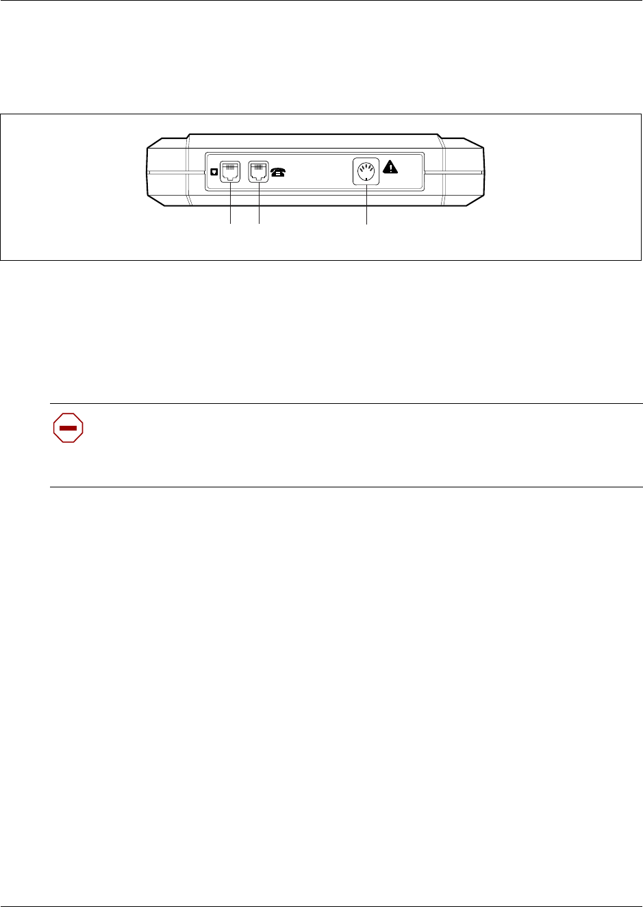
Chapter 13 Install Analog Terminal Adapters 281
Installation and Maintenance Guide
Use this procedure to connect the cable.
1Connect one end of a line cord to the ATA2 Terminal jack. Refer to Figure 181.
Figure 181 ATA 2 top view
2Connect the other end to your telephone, modem or FAX.
3Connect one end of a line cord to the ATA2 Line jack.
4Connect the other end to an available station port on the Business Communications Manager.
5For a 120 V or 230 V system, plug the DIN connector of the power supply cord into the power
supply connector receptacle. Plug the adapter into a standard ac outlet.
6This procedure is complete.
Mount the Business Communications Manager ATA 2
Use this procedure to mount the unit on a wall after the ATA 2 is correctly connected.
1When using 0.5 mm wire (24 AWG), select a location within 800 m (2,600 ft.) of the Business
Communications Manager system.
2Allow 12.5 cm (5 in.) clearance for the line jack, terminal jack, and power supply connector.
3Screw two 4 mm (#8) screws into the wall, 130 mm (5 1/4 in.) away from each other. Leave 6
mm (1/4 in.) of the two screws showing.
4Align the slots at the back of the Business Communications Manager ATA 2 unit over the
screws. Push the unit against the wall. The line jack, terminal jack and power supply connector
must be at the top of the Business Communications Manager ATA 2. Refer to Figure 182 on
page 282.
Caution: In North America, the Business Communications Manager ATA 2 must be
powered from a Class 2 power source that is UL and CSA approved.
In Europe, the Business Communications Manager ATA 2 must be powered from a Class
II power source that is CE marked.
=
24 V ~
0.006 A
Terminal jackLine jack Power supply connector receptacle
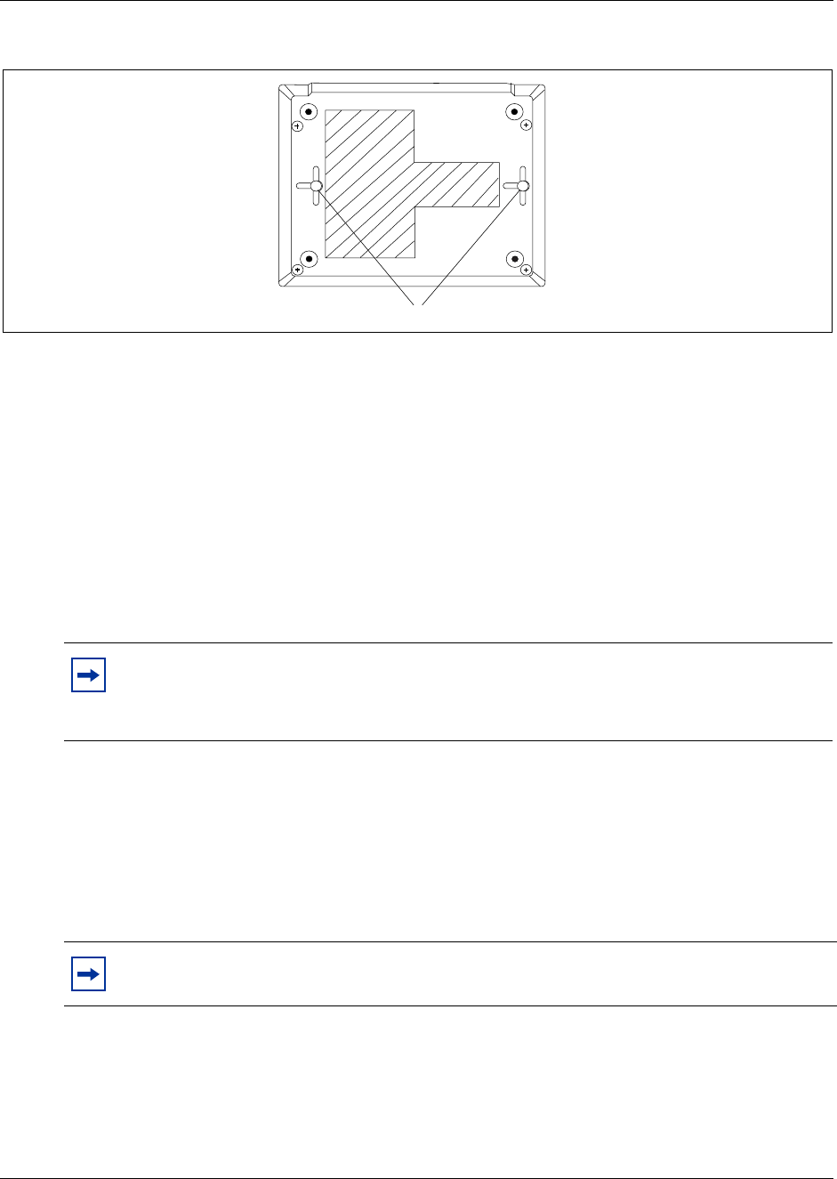
282 Chapter 13 Install Analog Terminal Adapters
P0993133 03
Figure 182 ATA 2 back view
5This procedure is complete.
Determine the ATA 2 extension number
Use this procedure to determine the extension number for every Business Communications
Manager ATA 2. Perform this procedure before performing administration.
1Connect a single-line telephone to the Business Communications Manager ATA 2.
2Lift the handset.
3If you do not hear dial tone, press °· to access an intercom line.
4Dial the extension number of an Business Communications Manager telephone with a display.
If you hear a busy signal, repeat steps 3 and 4 using a different extension number.
5When the telephone rings, the display shows: Set <nn> calling.
6The number that appears on the display is the Business Communications Manager ATA 2
extension number. Record the extension number.
7This procedure is complete.
Note: ° appears as ¿ on some telephones. If you are using a telephone without a ° or ¿
button, refer to the ATA 2 User Guide for details.
Some phones have a Flash button, which is the equivalent to ° or ¿.
Note: The Automatic Set Relocation feature works with Business Communications
Manager ATA 2.
Mounting keyhole slots

Chapter 13 Install Analog Terminal Adapters 283
Installation and Maintenance Guide
Configure the ATA 2
Use this procedure to configure the Business Communications Manager ATA 2 using the Business
Communications Manager Unified Manager. For detailed information about using Unified
Manager, refer to the Business Communications Manager 3.0, Programming Operations Guide.
1Open the Unified Manager.
2Assign the following line features to the Business Communications Manager ATA 2:
• assign one external line to the telephone
• set ringing for this line ON or OFF, as required
• assign one intercom line
• assign Held Line Reminder to ON
• disable Full Handsfree
• disable Handsfree Answerback
• disable Paging Reception
3Assign an external line, an intercom line, or a line pool as the Prime Line for the Business
Communications Manager ATA 2.
4Exit the Unified Manager.
5Set the Business Communications Manager ATA 2 to Tones ON when you are assigning an
analog voice device.
Set the Business Communications Manager ATA 2 to Tones OFF when you are assigning a
data communication device.
For details, refer to the Business Communications Manager ATA 2 User Guide. The default is
Tones OFF.
6This procedure is complete.
Test the ATA 2
Confirm that the Business Communications Manager ATA 2 is operating by connecting a
single-line telephone to the Business Communications Manager ATA 2. Make an internal call and
an external call using the telephone connected to the ATA 2. Next, call the Business
Communications Manager ATA 2 from an system telephone. Refer to the Business
Communications Manager ATA 2 User Guide for details.
Note: Direct access to a CO line for modems, fax machines and credit card
verification machines is possible using the Hotline feature. For direct access to a
CO line, program an external line as the Hotline. Enter a pause to replace the
telephone number for the Hotline (F78).
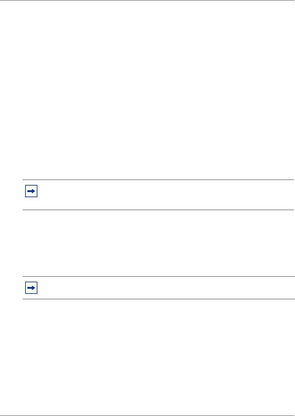
284 Chapter 13 Install Analog Terminal Adapters
P0993133 03
ATA 2 Data Communication
The Business Communications Manager ATA 2 connects a standard analog data device, such as a
FAX or modem, to the Business Communications Manager system. This section shows the
additional steps required to install ATA 2 for data communication.
Data transmission requirements
When using the Business Communications Manager ATA 2 for data transmission, the analog loop
resistance must not exceed 200 ohms. (for example: 730 m of 0.4 mm wire or 2,400 ft. of 26 AWG
wire.)
The external line assigned to the ATA 2 must follow the transmission network requirements
described in the data communication device specifications.
Transmission rates (baud) over 1,200 bps require a modulation design compatible with the
telephone line bandwidth. Use a conditioned external line to prevent data corruption during
transmission.
FAX and modem transmission compatibility
The Business Communications Manager ATA 2 is compatible with all commercial FAX and
modem protocols. When connected to an ATA 2, the Business Communications Manager system
supports data transmission rates a maximum of and including 28.8 kbit/s.
Note: Maximum loss from the ATA 2 analog terminal to the CO must be 10 dB or less at
1 kHz. If the loss exceeds this limit, condition the line. This loss ensures correct data
transmission for different types of data terminals.
Note: Nortel Networks cannot guarantee the maximum data transmission rate because the
maximum rate is subject to the quality of the end-to-end channel.
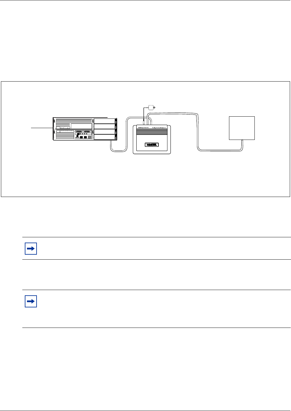
Chapter 13 Install Analog Terminal Adapters 285
Installation and Maintenance Guide
Install a Data Communication Device
Use this procedure to install an ATA 2 to a data communication device.
Figure 183 shows the hardware configuration for connecting a data communication device through
an ATA 2 to the Business Communications Manager.
Figure 183 Data communication device installation overview
1Connect a single-line telephone to the Business Communications Manager ATA 2.
2Check that the Business Communications Manager ATA 2 is in the Tones OFF mode, lift the
handset and press: °e°.
3Make sure the terminal loop resistance is less than or equal to 200 ohms.
4Disconnect the single-line telephone from the ATA 2.
5Plug the data communication device into ATA 2.
6This procedure is complete.
Note: ° appears as ¿ on some telephones. If you are using a telephone without a ° or ¿
button, refer to the ATA 2 User Guide for details.
Note: If necessary, install the Business Communications Manager ATA 2 near to the data
communication device to maintain a maximum loop resistance of less than 200 ohms.
When using 0.4 mm wire (26 AWG), the ATA 2 must be within 800 m (2,600 ft.) of the
Business Communications Manager system.
Data communication device
Business Communications
Manager ATA 2
Business Communications Manager
Line loop resistance:
135 ohms maximum Terminal loop resistance:
200 ohms maximum
Central
Office
ATA 2 power cord

286 Chapter 13 Install Analog Terminal Adapters
P0993133 03
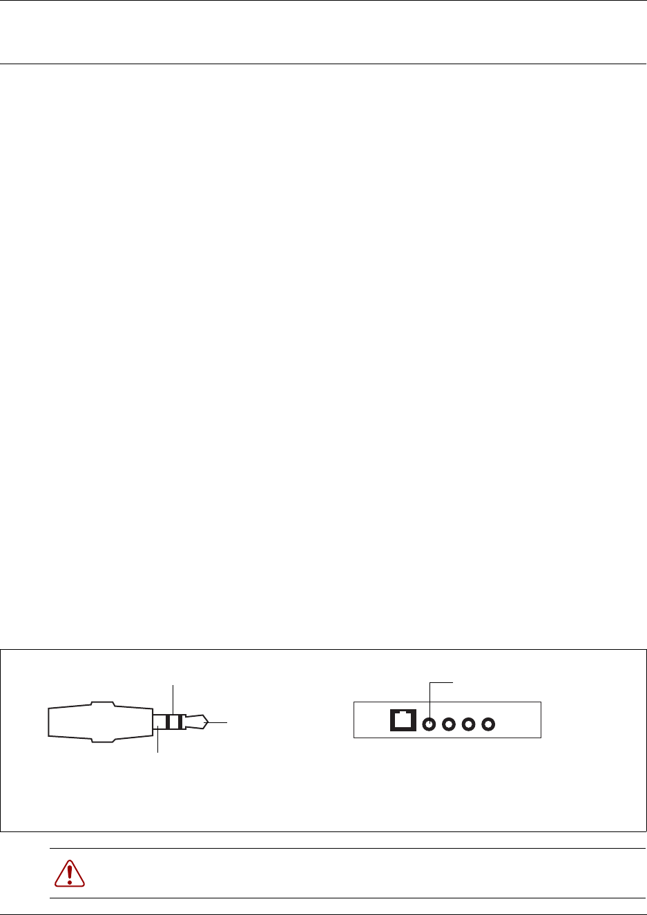
287
Installation and Maintenance Guide
Chapter 14
Install Optional Telephony Equipment
Use the procedures described in this chapter to connect the optional ringer, page, and music
telephony equipment to the media services card (MSC) connectors. Locate the MSC connectors on
the front of the Business Communications Manager base function tray. Refer to “Media services
card (MSC)” on page 57.
Media Service Card Connections
The MSC faceplate provides the following connections for optional telephony equipment:
• Auxiliary ringer
• Page relay
•Page output
• Music on hold
Install an auxiliary ringer
An auxiliary ringer is a customer-supplied piece of hardware that provides external ringing
capability to telephones on the Business Communications Manager, if the telephones are set to
allow it.
Use this procedure to install an auxiliary ringer.
1Use the installation instructions that came with the ringer hardware to install the auxiliary
ringer.
2Connect the ringer generator miniature jack to the auxiliary ringer output on the MSC. Refer to
Figure 184.
Figure 184 Auxiliary ringer jack
Warning: The auxiliary ringer must not be connected to exposed plant.
The ringer must not draw more than 50 mA from a 40 V DC source.
Tip
Ring
Sleeve
Auxiliary ringer jack
Tip: Auxiliary relay output
Ring: Auxiliary relay output
Sleeve: Ground
Auxiliary ringer
MSC Faceplate

288 Chapter 14 Install Optional Telephony Equipment
P0993133 03
Activate auxiliary ringer programming
You can activate the auxiliary ringer by setting auxiliary ring for specific external lines and
Business Communications Manager telephones. Refer to the Business Communications Manager
3.0, Programming Operations Guide for programming details.
Connect the external paging system
You can connect a customer-supplied external paging system to provide paging over external
loudspeakers.
Ensure the paging system follows these guidelines:
• The paging output from the MSC is 100 mV rms across an input impedance of 600 :.
• The output level is 0 dBm0 with reference to 600 ohms, for a PCM encoded signal at 0 dBm.
There is no dc voltage across the page output terminals.
• The page output uses the tip and ring terminals of the jack. The sleeve terminal of the jack
connects to ground. You must use a stereo plug to connect the page signal output.
When you use the page signal output jack to connect an external paging amplifier, you also use the
page relay jack which contains a floating relay contact pair. The system uses this jack to control
the external paging amplifier.
• The contact pair has a switch capacity of 50 mA (non-inductive) at 40 V (maximum). You
must remove any inductive load on the output.
• The page relay contacts connect to the tip and ring terminals of the jack. The sleeve terminal of
the jack connects to ground. You must use a stereo plug to connect the page relay.
Use this procedure to install the external paging system using the installation instructions that
came with the paging system.
1Connect the paging system audio input to the Page output on the MSC. Refer to Figure 185.
Figure 185 Audio input jack
2Connect the paging system relay to the Page relay output on the MSC. Refer to Figure 186.
Tip
Ring
Sleeve
Audio input jack
Tip: Page signal
Ring: Page signal
Sleeve: Ground
Page output
MSC Faceplate
Chapter 14 Install Optional Telephony Equipment 289
Installation and Maintenance Guide
Figure 186 Page relay jack
3This procedure is complete.
Connect an external music source
Use this procedure to connect the external music source to the Business Communications Manager
jack. You can use any customer-supplied approved low power device as a music source. A music
source includes equipment such as a radio with a high impedance earphone jack, as a music
source.
Music on hold specifications
Ensure that the music source follows these guidelines.
• Nominal input impedance is 3.3 kilohms.
• Nominal sensitivity of this interface returned to digital encoded PCM is
-22 dBm0 for a 0.25 V rms input signal.
• The input is limited so that the encoded analog content at the digital interface to the network
does not exceed -12 dBm when averaged over any three-second interval.
• The maximum non-clipped input level is 1 V rms.
• The interface is protected against ringing cross.
Warning: The paging connections must not be connected to exposed plant.
Tip: Paging tips
Business Communications Manager external paging does not support talk back paging
equipment unless you use an external line port.
The Business Communications Manager system provides paging over the telephone
speakers when there is no external paging equipment.
Tip
Ring
Sleeve
Page relay jack
Tip: Page relay output
Ring: Page relay output
Sleeve: Ground
Page relay
MSC Faceplate
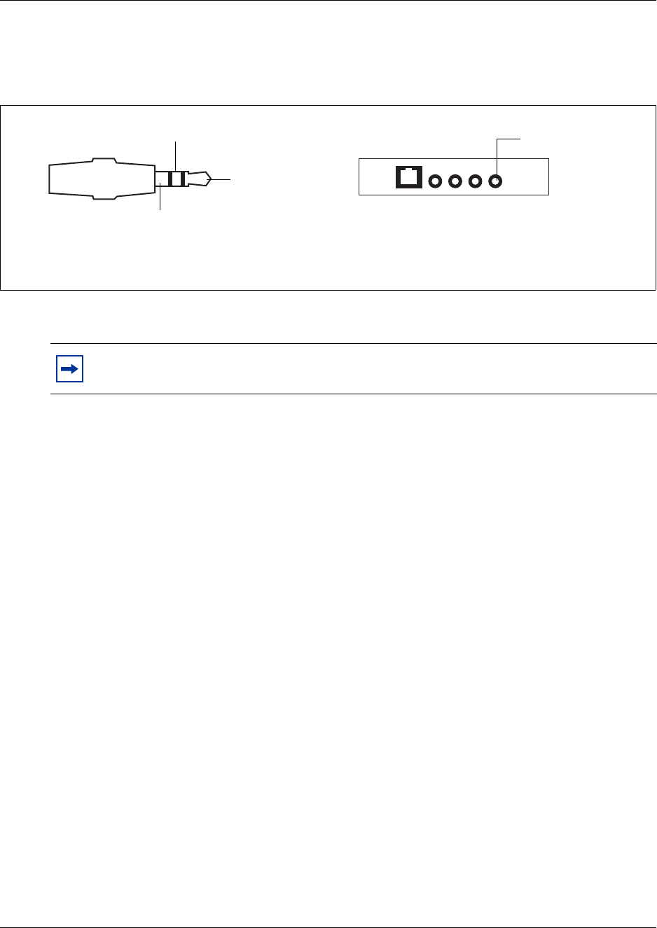
290 Chapter 14 Install Optional Telephony Equipment
P0993133 03
1Connect the miniature jack of the music source output to the music-on-hold input on the MSC.
Refer to Figure 187.
Figure 187 Music on hold jack
2Adjust the volume of the music source to a good level by activating Background Music and
adjusting the volume at the music source.
3Enable Music for callers on Hold and for Background Music through programming. Refer to
the Business Communications Manager 3.0, Programming Operations Guide for more details.
4This procedure is complete.
TIP: You can adjust the Background Music volume at every telephone.
Tip
Ring
Sleeve
Music jack
Tip: Music signal
Ring: No connection
Sleeve: Ground
Music-on-hold
input
MSC Faceplate
291
Installation and Maintenance Guide
Chapter 15
Troubleshooting
This chapter describes troubleshooting options to determine the cause of malfunctions or failure of
the Business Communications Manager hardware.
To analyze a Business Communications Manager problem, you must determine the cause of the
problem and if there is a damaged hardware component.
After you have corrected the problem, test the Business Communications Manager system to
confirm that the system is functioning correctly.
Hardware problems appear as any of the following:
• The operational LEDs on the Business Communications Manager base function tray, advanced
function tray (RAID upgrade) or the media bay modules do not display normal operational
status.
• Business Communications Manager system does not function at all.
• The emergency telephone does not function.
• ATA 2 does not function.
Danger: Electrical shock warning.
Disconnect the power cord, telephone cables and network cables before opening the
computer. Read and follow installation instructions carefully.
Warning: Protect the hardware components against damage from electrostatic discharge.
Always wear a ground wrist strap before you handle components. Always place the
components in static-free container.
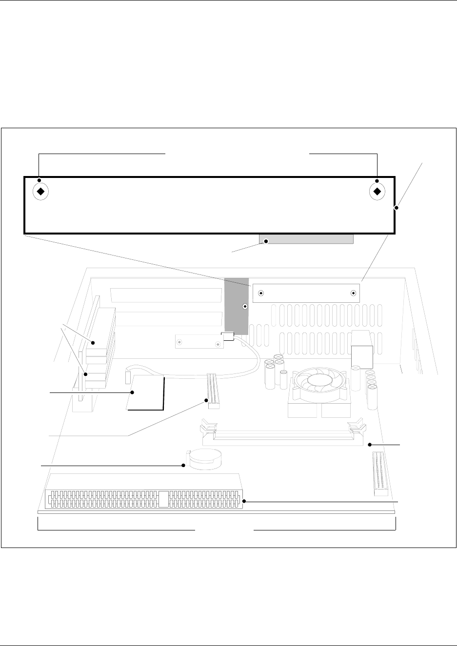
292 Chapter 15 Troubleshooting
P0993133 03
Access the System Status Monitor to Monitor LEDs
The LEDs on the Business Communications Manager base function tray are part of the System
Status Display (SSD) board.
Figure 188 shows what the board looks like from inside the base function tray.
Figure 188 SSD board connections
Figure 189 shows what the LEDs look like on the outside of the base function tray. The labels in
the illustration indicate which part of the hardware each LED supports.
PCI Riser
card
connectors
Modem
card
Main card
DIMM
connector
I/O card
connector
BIOS
battery
Main card
connector
System status monitor board
mounting screws SSM board
SSM Main
card
connector
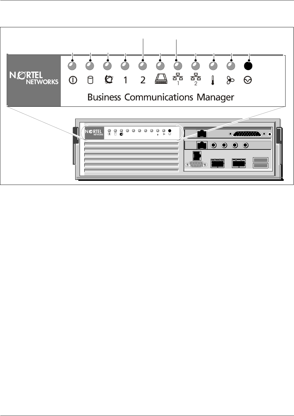
Chapter 15 Troubleshooting 293
Installation and Maintenance Guide
Figure 189 LED locations on the face of the base function tray
The Business Communications Manager System Status Monitor allows you to view the status of
the system LEDs on your PC. This status display allows you to make preliminary decisions
regarding the type of intervention required without necessarily having to inspect the Business
Communications Manager hardware.
Use this procedure to access the System Status Monitor through the Unified Manager:
1Open the Unified Manager.
2Under Diagnostics, click on System Status Monitor.
The LED Display screen appears.
12345
BCM400
Power StatusDisk Temp ResetFanMSC
WAN
Modem
LAN 1
LAN 2
Red or Green
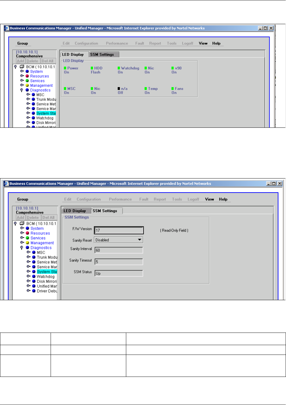
294 Chapter 15 Troubleshooting
P0993133 03
Figure 190 System Status Monitor LED Display screen
This screen displays the current status of the operational LEDS.
3To set the parameters for the System Status Sanity check, click the LED Settings tab.
The LED Settings record appears.
Figure 191 System Status Monitor LED Settings record
Table 34 lists the values on the LED Settings screen.
Table 34 LED Display screen settings
Attribute Values Description
Version Read only. The current version of the LED monitoring application.
Reset Yes, No, N/A Use Yes to allow the system status monitor board to reset the
computing platform in the event that the sanity check fails the
user set parameters.

Chapter 15 Troubleshooting 295
Installation and Maintenance Guide
4This procedure is complete.
Business Communications Manager does not Function
The Business Communications Manager can experience a complete failure for any of the
following reasons:
• Power supply failure
• Incorrect power supply connections
• AC power failure
Sanity Time 60-255
Default: 240
The time in seconds between sanity checks.
Timeouts 0-254
Default: 10
The number of sanity checks that must fail before the system
status monitor sends a reset signal to the computing platform.
Table 34 LED Display screen settings (Continued)

296 Chapter 15 Troubleshooting
P0993133 03
Emergency Telephone Does Not Function
If the emergency telephone is connected to the system, use the following procedure:
1Check the power LED on the ASM 8 to check that the ASM 8 is receiving power.
2Check that the emergency telephone has dial tone.
3Check the external line and emergency telephone connections.
4To avoid damage to the emergency telephone, connect the telephone directly to the external
line and check for dial tone.
5Replace the MSC.
6This procedure is complete.
If the emergency telephone is connected to the CTM, use the following procedure:
1Check that the system has a CTM installed.
2Check that there is no dial tone at the emergency telephone.
3Replace the CTM.
4This procedure is complete.
ATA 2 Does Not Function
If the Business Communications Manager ATA 2 does not function. Follow these steps to
troubleshoot the problem.
1Make sure there is ac power connected to the ATA 2 unit.
2Make sure that ATA 2 is in the Tones OFF mode. (For Data Applications only).
3Correctly configure the ATA 2 telephone port for data communication.
4Allow sufficient start up time.
5Assign the prime line.
6Assign a ringing line if required, for example, auto-answer modems, FAX.
7This procedure is complete.

Chapter 15 Troubleshooting 297
Installation and Maintenance Guide
Check the ATA 2 wiring
Check the following connections:
1ATA 2 to the terminal. The resistance must be 200 ohms or less for data applications and 1,300
ohms or less for voice applications.
2Business Communications Manager system to ATA 2. The wiring must be equivalent to 800 m
of 0.5 mm wire (2,600 ft. of 24 AWG) or less. Do not use bridge taps and loading coils
between the Business Communications Manager system and ATA 2.
3External line to the Business Communications Manager system. Ensure the external line is
correctly connected to the Business Communications Manager system and make sure there is
dial tone.
4This procedure is complete.
Check for dial tone at the ATA 2
Check to ensure there is dial tone from the set and from the ATA 2 module.
1If there is no dial tone, replace a single-line telephone for the data communication device.
2If there is no dial tone at the ATA 2 unit:
aDisconnect the line side of ATA 2. Connect an Business Communications Manager
telephone to the ATA 2 port.
bCheck that the connection from ATA 2 to the Business Communications Manager system
is functioning correctly (the telephone has dial tone).
3This procedure is complete.
Check for trunk line dial tone to the ATA 2
Use the following steps to check for trunk line dial tone to the ATA 2.
1Disconnect ATA 2 external line from the Business Communications Manager system and
connect the data device directly to this external line.
2Make a call.
3If the problem continues, the device or the external line is possibly at fault.
4Plug the device into a different line.
5If the problem continues, the device is possibly at fault.
6This procedure is complete.
For more information about ATA 2, contact your customer service representative.

298 Chapter 15 Troubleshooting
P0993133 03

299
Installation and Maintenance Guide
Appendix A
System Region Attributes
This appendix provides a number of tables that show the relationship of system programming to
the region or software that you select at system startup.
Each region is designed using a set of system defaults that provide specific functionality for the
region in which the system is deployed. This can include specific languages, and a specific order in
which the languages are set as default (language 1), whether Companion or DECT mobility will be
allowed, and what type of trunks can be used.
Core Software and Regions
Each Region setting requires a specific core software to perform correctly. Table 35 shows the core
software available.
Table 35 Core software, defined by region and carrier profile
Core Software
(Carrier s/w ID) T1 CT2 Plus T1 Etiquette E1 Euro E1 Global E1 CALA
Region Caribbean
Hong Kong
North American
Taiwan
Caribbean
Hong Kong
North American
Taiwan
Denmark
Europe
France
Germany
Holland
Italy
Norway
Spain
Sweden
Switzerland
United Kingdom
Australia
CALA
Global
PRC
Australia
CALA
Global
PRC
South American and Central American countries are assigned to regions in the following way:
• Caribbean includes Antigua, Bahamas, Barbados, Bermuda, Cayman Islands, Dominican Republic,
Grenada, Jamaica, USVI, Puerto Rico, and Trinidad
• CALA refers to all other Caribbean and Latin American countries with European-based standards.

300 System Region Attributes
P0993133 03
Language Availability
Table 36 lists the languages available for each region and a specific order in which the languages
are set as default.
Table 37 shows a breakdown of the language support for South American and Central American
countries.
Table 36 Languages
Region Language
CALA
Caribbean
Hong Kong
North American
PRC
Taiwan
NA English, NA French, NA Spanish
Australia
United Kingdom UK English
Denmark Danish, Norwegian, Swedish, NA English
France Euro French, NA English
Germany German, NA English
Global NA English, NA French, NA Spanish, Turkish
Holland Dutch, Euro French, NA English
Italy Italian, NA English
Norway Norwegian, Swedish, Danish, NA English
Spain Euro Spanish, NA English
Sweden Swedish, Norwegian, Danish, NA English
Switzerland German, Euro French, Italian, NA English
Table 37 South/Central America language breakout
Language Spanish English French
Country Dominican Republic
Jamaica
Puerto Rico
Argentina
Bolivia
Chile
Columbia
Costa Rica
Guatemala
Mexico
Nicaragua
Peru
Panama
Uruguay
Venezuela
El Salvador
Honduras
Ecuador
Paraguay
St. Thomas
USVI
Aruba
Bahamas
Bermuda
Curacao
Trinidad
Anguilla
Antigua
Barbados
Dominica
Grenada
Guyana
Montserrat
St. Kitts
St. Lucia
St. Maarten
Suriname
Turks & Caicos
St. Vincent
St. Thomas
Cayman Islands
Belize
Haiti

System Region Attributes 301
Installation and Maintenance Guide
Caller ID Displays
The North American region supports the following format: 5554775 (613)
All other regions display the numbers in a continuous string of a maximum of 14 characters:
6135554775
Companding Law by Region
Table 38 shows the companding law used for each region.
ISDN Line Services
Table 39 shows the ISDN private network services that are supported by the Business
Communications Manager. Table 40 shows the network-based ISDN supplementary services and
the features available for each.
Table 38 Companding law
Companding Law
µ-law A-law
Caribbean
Hong Kong
North American
Taiwan
Australia
CALA
Denmark
France
Germany
Global
Holland
Italy
Norway
PRC
Spain
Sweden
Switzerland
United Kingdom
Table 39 ISDN line services
MCDN over PRI (SL-1) DPNSS DASS2 ETSI QSIG
Basic Call Basic Call Basic Call Basic Call
DDI DDI DDI DDI
Name display Diversion Originating line identity (OLI) Name display
Number display Redirection Terminating Line Identity (TLI) Number display
Centralized voice mail Centralized voice mail Call Charge Indication (CCI)

302 System Region Attributes
P0993133 03
Camp-on Call Offer Call Charge Rate Indication (CCRD)
ISDN Call Connection Limit Loop avoidance
Network Call Transfer Executive Intrusion
Break-in Three Party
Trunk Route Optimization (TRO) Route Optimization
Trunk Anti-Tromboning
Table 40 ISDN services, by Protocol
Protocol Available ISDN services
NI
(Caribbean. North America)
Basic Call
DID
Name display
Number display
ONN blocking
ETSI Euro
(Australia. CALA, Denmark, France,
Germany, Global, Holland, Hong
Kong, Italy, Norway, PRC, Spain,
Sweden, Switzerland, Taiwan, United
Kingdom)
Basic Call
DDI
sub addressing (on S-loop)
ETSI Call Diversion (partial rerouting)
AOC-E (specific changes for Holland and Italy)
MCID
CLIP
COLP
CLIR
Table 39 ISDN line services (Continued)
MCDN over PRI (SL-1) DPNSS DASS2 ETSI QSIG

System Region Attributes 303
Installation and Maintenance Guide
Mobility Services by Region
Table 41 shows the Mobility services that are supported by the Business Communications
Manager, and the regions that can use each type.
Media Bay Module Availability by Region
Some of the media bay modules are customized for a specific type of line and are not available to
all regions. Table 42 lists a cross-reference between regions and the type of modules that can be
used within the related area.
Table 41 Mobility services, by region
Profile Available Mobility Service
Caribbean
North American
PRC
Companion (CT2-Plus, Etiquette)
CALA Companion (CT2-Plus)
Hong Kong
Taiwan Companion (CT2-Plus, Etiquette)
DECT
Australia
Denmark
France
Germany
Global
Holland
Italy
Norway
Spain
Sweden
Switzerland
United Kingdom
DECT
Table 42 Module availability, by profile
Region DSM16+/
DSM32+ ASM CTM/
CTM8 4X16 BRI DTM DECT DDIM
Australia 9 9 9 9 9
Caribbean 9 9 9 9 9 9
CALA 9 9 9 9 9 9
Denmark 9 9 9 9 9
France 9 9 9 9 9
Germany 9 9 9 9 9
Global 9 9 9 9 9 9 9
Holland 9 9 9 9 9

304 System Region Attributes
P0993133 03
Trunk Availability by Region
Different countries have different available trunk types. Table 42 provides a cross-reference
between regions and available trunks types.
Hong Kong 9 9 9 9 9 9 9
Italy 9 9 9 9 9
North American 9 9 9 9 9 9 9
Norway 9 9 9 9 9
PRC 9 9 9 9 9 9
Spain 9 9 9 9 9
Sweden 9 9 9 9 9
Switzerland 9 9 9 9 9
Taiwan 9 9 9 9 9 9 9
United Kingdom 9 9 9 9 9
Table 43 Trunk availability, by region
Region BRI S/T 2/4 BRI U2/4
PRI
ETSI = 30 channels
NA = 23 channels Analog DID E&M CLASS
Country-
specific
analog
trunk card
Australia 9 9 9
CALA 9 9 9 9 9 9
Caribbean 9 9 9 9 9 9
Denmark 9 9
France 9 9 9
Germany 9 9 9
Global 9 9 9 9
Holland 9 9 9
Hong Kong 9 9 9 9 9
Italy 9 9
North American 9 9 9 9 9 9
Norway 9 9
Table 42 Module availability, by profile (Continued)
Region DSM16+/
DSM32+ ASM CTM/
CTM8 4X16 BRI DTM DECT DDIM

System Region Attributes 305
Installation and Maintenance Guide
PRC 9 9 9 9
Spain 9 9
Sweden 9 9
Switzerland 9 9
Taiwan 9 9 9 9 9
United Kingdom 9 9 9
Table 44 PRI line protocol supported, by region
Region BRI T side BRI S side PRI T1
Australia ISDN ETSI 300 403 ISDN ETSI 300 102 DASS2
DPNSS
MCDN
ISDN ETSI 300 403,
ETSI QSIG 300 239,
Brazil
CALA
ISDN ETSI 300 403,
ETSI QSIG 300 239 ISDN ETSI 300 102 ETSI QSIG 300 239,
ISDN ETSI 300 403,
MCDN
Caribbean
North American
NI-2 NI-2 NI-2
4ESS
DMS100
DMS250
MCDN
Loop
E&M
DID
Ground
Fixed trunk types
Hong Kong
Taiwan
ITU-T ITU-T ITU-T Loop
E&M
DID
Ground
Fixed trunk types
Denmark
France
Germany
Global
Holland
Norway
PRC
Spain
Sweden
Switzerland
ETSI QSIG 300 239,
ISDN ETSI 300 403 ISDN ETSI 300 102 DASS2
DPNSS
MCDN
ETSI QSIG 300 239
ISDN ETSI 300 403
Table 43 Trunk availability, by region (Continued)
Region BRI S/T 2/4 BRI U2/4
PRI
ETSI = 30 channels
NA = 23 channels Analog DID E&M CLASS
Country-
specific
analog
trunk card

306 System Region Attributes
P0993133 03
BRI and PRI line types
Table 45 provides a description of the types of lines that BRI and PRI trunks can provide. These
are set under Resources/Media Bay Modules/Bus XX/Module X on the Unified Manager.
Note that some of these line types are only available when specific regions are chosen.
Italy ISDN ETSI 300 102
ETSI QSIG 300 239 ISDN ETSI 300 102 DASS2
DPNSS
MCDN
ETSI QSIG 300 239
ISDN ETSI 300 102
United Kingdom ETSI QSIG 300 239,
ISDN ETSI 300 403 ISDN ETSI 300 102 DASS2
DPNSS
MCDN
ETSI QSIG 300 239
ISDN ETSI 300 403
Table 45 BRI and PRI line types (DTM and BRI modules)
Digital trunk types Description
T1 digital line that carries data on 24 channels at 1.544 Mbps (North American); 30 channels
at 2,048 Mbps (Europe)
Loop, E&M, DID and ground start lines are also versions of T1 lines.
You can program auto-answer T1 loop start, T1 E&M trunks, T1 DID, T1 ground start
trunks, PRI and IP trunks to map to target lines to provide for attendant bypass (calling
directly to a department or individual) and line concentration (one trunk can map onto
several target lines).
DID This is a type of T1 trunk line that allows an outside caller to dial directly into a line on the
Business Communications Manager 2.5.
Loop This is a type of T1 line. This type of line is used on systems where the service provider
supports disconnect supervision for the digital loop start trunks.
These trunks provide remote access to the Business Communications Manager from the
public network. This trunk must have disconnect supervision to allow the trunk to be set to
auto-answer, which provides the remote access portal.
Ground T1-groundstart trunk
These lines offer the same features as loop start trunks, but are used when the local
service provider does not support disconnect supervision for digital loop start trunks.
Ground start trunks work with T1 only. By configuring lines as ground start, the system will
be able to recognize when a call is released at the far end.
E&M T1 and E&M. This type of trunk line is used to create simple network connections to other
phone systems.
This trunk always operates in a disconnected supervised mode.
Table 44 PRI line protocol supported, by region (Continued)
Region BRI T side BRI S side PRI T1

System Region Attributes 307
Installation and Maintenance Guide
PRI ISDN interface with 23 B channels and 1 D channel at 1.544 MBps (in Europe: 30 B
channels and 2 D channels at 2.048 Mbps)
This is the module that controls system timing.
These lines give you incoming and outgoing access to an ISDN network and are
auto-answer trunks, by default.
These lines provide a fast, accurate and reliable means of sending and receiving data,
images, text and voice information. using PRI lines allows for faster transmission speeds
and the addition of a variety of powerful business applications, including remote LAN
access, video conferencing, file transfer and internet access.
BRI ISDN loop that provides both T, S and U2 and U4 (region-specific) reference point loops.
These loops can support both network (T and S loops) and terminal equipment (S loop)
connections.
This type of line provides incoming and outgoing access to an ISDN network. ETSI ISDN
BRI is the European Telecommunications Standards Institute specification for BRI ISDN
service. BRI provides two bearer B-channels operating at 64 kbits/s and a data D-channel
which operates at 16 kbits/s. The D-channel is used primarily to carry call information. Like
loop start trunks, BRI lines can be configured as manual-answer or auto-answer.
DASS2 (British) Trunk provides multi-line IDA interconnection to the British Telecom network.
DPNSS (international term: Q.Sig or Q.931) a digital private network signaling system which allows
phone systems from different manufacturers to be tied together over E1 lines, offering
significant enhancements to Business Communications Manager 2.5 networking
capabilities.
DPNSS makes it easier to support centralized network functionality within private networks,
for operators and attendants dealing with large numbers of calls. Its routing capabilities
provide more of the larger-network capabilities without the expense of installing a new
system, re-configuring all the nodes and worrying about a lot of downtime. Most
functionality over DPNSS lines is transparent once the DPNSS is programmed into the
system.
DPNSS allows a local node, acting as a terminating node, to communicate with other PBXs
over the network using E1 lines. For example, corporate offices separated geographically
can be linked over DPNSS lines to other Business Communications Manager 2.5 systems,
bypassing the restrictions of the PSTNs to which they may be connected. This allows
connected Business Communications Manager 2.5 systems to function like a private
network.
Analog trunk types
Public Provides potential access for any set on the system.
Private Provides potential access for a specific set.
Table 45 BRI and PRI line types (DTM and BRI modules) (Continued)
Digital trunk types Description

308 System Region Attributes
P0993133 03
Define Time Zones by Country and Language
Time zones are based on the actual time zone where the Business Communications Manager
system is located. The Time Zone dropdown list on the initialization screen, allows you to be very
specific in choosing a compatible time zone. If your exact location is not on the list, choose the one
with the time zone closest to you. Note that some time zones are individualized because they do
not switch from Standard Time to Daylight Saving Time. For example, this is the case for
Saskatchewan.
The format of the time and date changes are based on the prime language of the region. Table 46
provides a list of formats based on language or country.
System Defaults
Table 47 compares the system defaults for the North American, Global and UK regions. In
addition, the following functionality applies:
• Regions for Denmark, Holland and Sweden are the same as the Global region except for the
default to local languages and local tones and cadences.
• The Region for the Caribbean is the same as the North American region except that it supports
the M7000 telephone.
• The Region for CALA is the same as the Caribbean region, except NI ISDN is replaced by
ETSI ISDN (u-law).
• The Region for Europe is the same as the United Kingdom region except there are no default
dialing restrictions, and ATA parameters are set to European values.
Table 46 Time/date formats based on language
Language/Country Time/Date format
Danish 2001-01-01 13:57
Dutch 1 Jan 01 13:57
EuroFrench 1 jan 13:57
EuroSpanish 1 Ene 13:57
German 1 Jan 13:57
Italian 1 Gen 13:57
NA English Jan 1 1:57 pm
NA French 2001-01-01 13:57
NA Spanish Ene 1 1:57 pm
Norwegian 1 Jan 13:57
Swedish 2001-01-01 13:57
Turkish 1 Ock 13:57
UK English 1 Jan 1:57 pm

System Region Attributes 309
Installation and Maintenance Guide
Table 47 Region defaults
Functionality Attribute North American Global United Kingdom
Direct Dial Access code 0 0 0
DTMF parameters Tone duration 120 msec 120 msec 120 msec
Pause time 1.5 1.5 3.5
Interdigit time 80 msec 80 msec 100 msec
Conference tone disabled disabled enabled
Call Back Kill time 180 sec 180 sec 360 sec
PCM Companding Law mu-law a-law EBI a-law EBI
Race Integration disabled disabled disabled
OLI digits fixed 10 digits fixed 10 digits variable length a
maximum of 8
Dial Tone Detection enabled enabled enabled
Hunt Groups Show in second disabled disabled disabled
Default delay 4 ring cycles 4 ring cycles 4 ring cycles
Queue timeout 60 sec 60 sec 60 sec
If busy busy tone busy tone busy tone
Mode broadcast broadcast sequential
Target line if busy setting prime prime busy tone
M7000 set disabled enabled enabled
Fax switch enabled enabled enabled
Service Schedule time Night start 23:00
end 07:00 start 23:00
end 07:00 start 23:00
end 07:00
Evening start 17:00
end 23:00 start 17:00
end 23:00 start 17:00
end 23:00
Lunch start 12:00
end 13:00 start 12:00
end 13:00 start 12:00
end 13:00
Service 4 start 00:00
end 00:00 start 00:00
end 00:00 start 00:00
end 00:00
Service 5 start 00:00
end 00:00 start 00:00
end 00:00 start 00:00
end 00:00
Service 6 start 00:00
end 00:00 start 00:00
end 00:00 start 00:00
end 00:00
Call Forward Delay Show in second disabled disabled disabled
Default 4 ring cycles 4 ring cycles 2 ring cycles
Options • 2 ring cycles
• 3 ring cycles
• 4 ring cycles
• 6 ring cycles
• 10 ring cycles
• 2 ring cycles
• 3 ring cycles
• 4 ring cycles
• 6 ring cycles
• 10 ring cycles
• 2 ring cycles
• 3 ring cycles
• 4 ring cycles
• 6 ring cycles
• 10 ring cycles

310 System Region Attributes
P0993133 03
DRT Delay Show in second disabled disabled disabled
Default 4 ring cycles 4 ring cycles 4 ring cycles
Options • 1 ring cycles
• 2 ring cycles
• 3 ring cycles
• 4 ring cycles
• 6 ring cycles
• 10 ring cycles
• 1 ring cycles
• 2 ring cycles
• 3 ring cycles
• 4 ring cycles
• 6 ring cycles
• 10 ring cycles
• 1 ring cycles
• 2 ring cycles
• 3 ring cycles
• 4 ring cycles
• 6 ring cycles
Handsfree none none none
Pickup Group none none none
Remind Delay 60 secs 60 secs 60 secs
Allow SLR disabled disabled disabled
Transfer Callback Show in second disabled disabled disabled
Default 4 ring cycles 4 ring cycles 4 ring cycles
Options • 3 ring cycles
• 4 ring cycles
• 5 ring cycles
• 6 ring cycles
• 12 ring cycles
• 3 ring cycles
• 4 ring cycles
• 5 ring cycles
• 6 ring cycles
• 12 ring cycles
• 3 ring cycles
• 4 ring cycles
• 5 ring cycles
• 6 ring cycles
• 12 ring cycles
Dialling Plan market dependent
(defined in
application but
controlled by
market profile ID)
market dependent
(defined in
application but
controlled by market
profile ID)
market dependent
(defined in application
but controlled by market
profile ID)
ONN Blocking VSC for analog
tone n/a n/a 141
VSC for analog
pulse n/a n/a 141
VSC for BRI n/a n/a 141
VSC for PRI n/a n/a 141
State for BRI/PRI n/a n/a send feature code
Default CO lines 2 2 4
UTAM enabled disabled disabled
Portable credits 0defined in the
application (max) n/a
Release reason Release text none none detail
Release code disabled disabled disabled
Display duration 3 sec 3 sec 3 sec
Overlap Receiving disabled enabled disabled
Local Number length for
ISDN overlap receiving 8 8 8
Table 47 Region defaults (Continued)
Functionality Attribute North American Global United Kingdom

System Region Attributes 311
Installation and Maintenance Guide
Tandem alerting disabled disabled disabled
TON/NPI national/E.164 national/E.164 unknown/unknown
National number length 10 10 0
national number prepend n/a n/a 0
Provide tone on PRI enabled n/a disabled
Table 47 Region defaults (Continued)
Functionality Attribute North American Global United Kingdom

312 System Region Attributes
P0993133 03
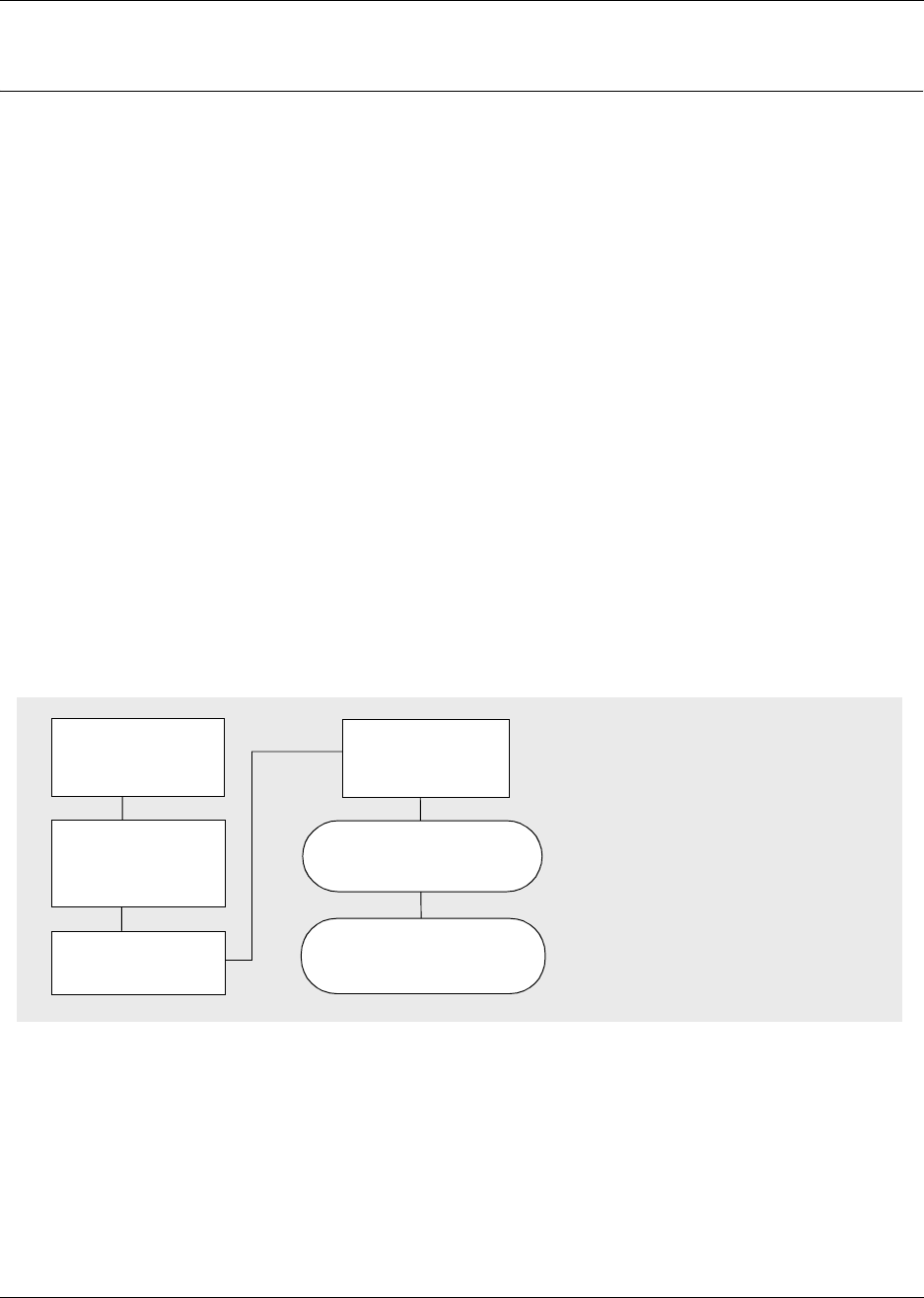
313
Installation and Maintenance Guide
Appendix B
Telephony Hardware Selection and Settings
Media Bay Module System Selection
The media bay modules are the devices in the Business Communications Manager system that
permit you to connect your extensions and the public switched telephone network (PSTN) lines to
the call processing capabilities of the Business Communications Manager system.
A special media bay module called a Fiber expansion module (FEM) allows you to update from a
Norstar system to a Business Communications Manager by reusing the Norstar expansion modules
and the fiber cables to the modules.
When you order your Business Communications Manager system, there are no media bay modules
installed in the Business Communications Manager base platform chassis or Business
Communications Manager expansion unit. You are able to select the number and type of media
bay modules that best suit your business requirements.
If you have a large Business Communications Manager system, there are some configuration
restrictions that can apply to your system. For information about these restrictions, refer to “Rules
for assigning DS30 resources” on page 322.
Figure 192 Process for determining modules
The first step in selecting the media bay modules is to establish the number of extensions (internal
lines) and PSTN lines (trunk lines) you have or need. This determines the number and type of
media bay modules you require. The following sections describe how to determine which
modules, and how many, you require for your system.
After you determine the modules types required, calculate how they use the available system
resources. These sections describe how the modules work within the available channels on the
Media Services Card (MSC) in the Business Communications Manager.
Determine DS30
requirements for
each module
Determine if any
offsets can be used
Set DIP switches on
modules
Install modules into the
BCM or expansion unit
Determine trunk
and extension
requirements
Determine which
DS30 buses are
available

314 Telephony Hardware Selection and Settings
P0993133 03
Trunk media bay module selection
The number and type of lines coming into your system determine which trunk media bay modules,
and how many modules, you require to support your needs. Trunk lines come from either the
public network (PSTN), or they support connections in a private network.
If you are setting up an entirely new system, a site survey must be done to determine your current
and future needs. Nortel Networks recommend that you do the survey before you order any
modules.
To select the trunk media bay modules:
1Record the number of each type of line you have in Table 48. If you do not know the number
or type of lines you have, contact your service provider.
2Use the number of lines and the number of lines per module to determine how many modules
you need.
Note: If you plan to add any lines in the near future, include them in your initial estimates.
Table 48 Determining trunk module requirements
Type of lines Number
of lines Type of media bay
module Number of lines
per module
Number of
modules
required
T1 digital lines DTM 24 ______ DTM
Universal T1 MUX digital
lines DDIM 24
(also requires a full DS30
channel for the Data
Module)
______ DDIM
PRI digital lines (NA) -
(required for Companion
wireless)
DTM 23 ______ DTM
E1 digital lines DTM 30 ______ DTM
PRI digital lines (EMEA) DTM 30 ______ DTM
Analog lines CTM
(North American systems only) 4 ______ CTM
Analog lines CTM8
(North American systems only)
8 ______ CTM
Analog lines 4X16 combination module
(North American system only)
4 (also requires a full
DS30 channel for the
DNs)
______ CTM
BRI ISDN lines BRIM S/T 4 ISDN loops ______ BRIM S/T
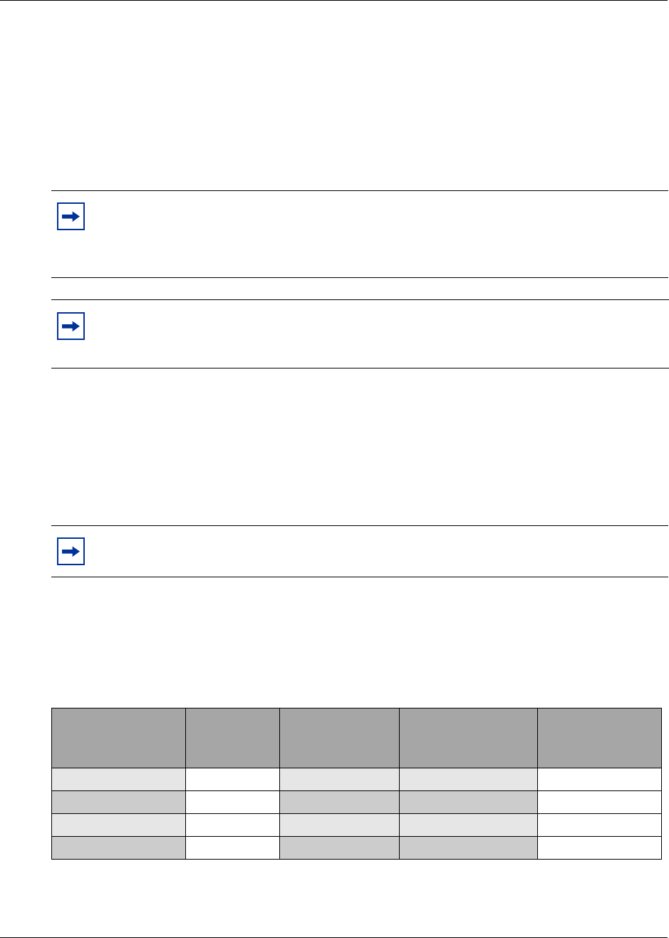
Telephony Hardware Selection and Settings 315
Installation and Maintenance Guide
* A Universal T1 MUX is a type of T1 digital line that contains a combination of digital telephone lines and data lines.
An example:
• If you require 24 T1 digital lines, you need one DTM because a single DTM can handle 24
T1 lines (North America).
• If you require two analog lines and 24 T1 digital lines, you need one CTM and one DTM.
3This procedure is complete.
Station media bay module selection
The number and type of telephones and related equipment you have determines which station
media bay modules you require.
1In Table 49, record the number of each type of extension you have.
2Use the number of extensions and the number of extensions per module to determine how
many modules you need.
Note: Although the DTM supports several types of digital lines, you cannot connect
different types of lines to the same DTM.
You can add a maximum of three DTMs or DDIMs to your Business Communications
Manager system.
Tip: The BCM400 platform base chassis holds a maximum of four media bay modules. If
you require more modules the Business Communications expansion unit supports a
maximum of six additional modules.
Note: If you are adding any extensions in the near future, include them in your
calculations.
Table 49 Station media bay modules required
Type of extension Number of
extensions Type of media bay
module
Number of
extensions
per module Number of
modules required
Digital extensions DSM 16/DSM 16+ 16 _____ DSM 16
Digital extensions DSM 32/DSM 32+ 32 _____ DSM 32
Digital extensions 4X16 16 _____ DSM 16
Analog extensions ASM 8 8 _____ ASM 8
316 Telephony Hardware Selection and Settings
P0993133 03
An example for North America:
• If you require 12 digital extensions, you need one DSM 16/DSM 16+
• If you require 24 digital extensions, you need one DSM 32/DSM 32+
3This procedure is complete.
Upgrade from an existing Norstar system
A special media bay module allows you to convert existing Norstar expansion modules from the
Norstar ICS to full Business Communications Manager capability.
The FEM allows you to connect a maximum of six Norstar expansion modules to a Business
Communications Manager. Each expansion module connection requires one DS30 channel,
therefore, the Business Communications Manager used for this purpose can only support one FEM
module if you are converting a fully-configured Norstar system.
Determine system capacity
After you have selected the modules you require, you must ensure that the Business
Communications Manager can support all the modules. This is determined by the line
requirements of each module.
Cordless handsets
(DECT)
(selected profiles
only)
DECT 32 ______ DECT
Digital extensions are digital or IP telephones. You do not need to include IP telephones when calculating
the number of required DSM modules. For a list of the telephones that can be used with the Business
Communications Manager system, refer to “Telephones and adapters” on page 85.
Analog extensions include single line telephones, fax machines, and modems.
Note: If you require only a few analog extensions, you can use an Business
Communications Manager ATA 2 to connect these devices to your DSM 16, DSM 32 or
the DSM connector on a 4X16 module. Each analog extension requires a Business
Communications Manager ATA 2.
Tip: The BCM400 can hold a maximum of four media bay modules. If you require more,
you also need an Business Communications Manager expansion unit.
Table 49 Station media bay modules required
Type of extension Number of
extensions Type of media bay
module
Number of
extensions
per module Number of
modules required
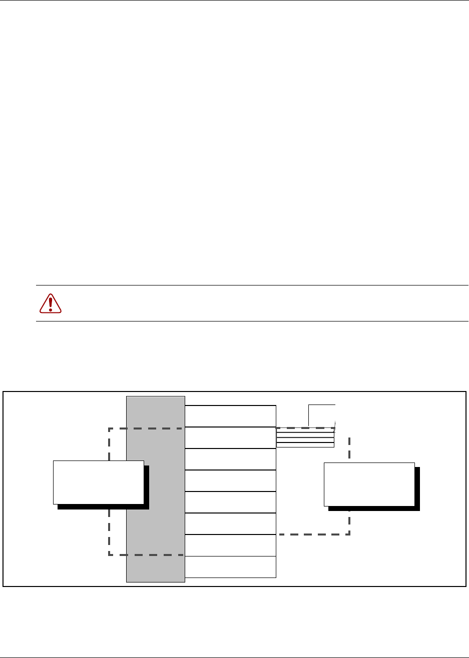
Telephony Hardware Selection and Settings 317
Installation and Maintenance Guide
The following sections describe the MSC DS30 buses, which manage the DS30 channels, and how
you fit your modules into the overall system planning.
Understand DS30 numbers
A DS30 bus is a block of virtual pathways on the media services card (MSC).
On a default system, six buses of DS30 channel blocks can be assigned to media bay modules.
Which block the module is assigned to determines the range of line (trunk) numbers or extension
numbers (DNs) that can be allocated by the module to the equipment connected to that module.
The other two blocks are permanently routed to the PEC digital signal processors (DSPs) to
support internal Business Communications Manager functions such as voice mail, VoIP trunks,
IVR, and IP telephony functions. This configuration is called a 2/6 channel split.
You can change the DS30 allocation to a 3/5 split to accommodate increased IP telephony or VoIP
trunk requirements. You do this by assigning bus 7 to the voice data sector. This choice should be
made at system startup, but a default system can be changed through the Unified Manager to a 3/5
split after startup if IP requirements increase. At startup, you indicate the split you want when you
run the Quick Start Wizard. Refer to the Programming Operations Guide for details.
Figure 193 shows a model of how the MSC DS30 buses are a subgroup of the DS256 bus on the
MSC. The diagram also shows the offset channels, which are a subgroup of the buses.
Figure 193 DS30 model
DS30 numbers are set using the number 4, 5, and 6 DIP switches on the back or underside of the
media bay modules. The exception is the FEM module. The FEM DIP switches turn on ports, each
of which consumes one bus.
Warning: If you change the channel split from 3/5 to 2/6 after your system is configured,
you will lose all the data and optional application connections.
DS256
on MSC
DS30 channel #2
DS30 channel #3
DS30 channel #4
DS30 channel #5
DS30 channel #6
DS30 channel #7
DS30 buses
available to modules
in a 2/6 split
Four offsets per bus
DS30 buses
available to modules
in a 3/5 split

318 Telephony Hardware Selection and Settings
P0993133 03
Setting offsets
Each offset is one-quarter of a DS30 bus. Each bus, supports 16 lines (32 time slots) for most
modules.
Exceptions:
• DTM modules support 23 to 30 lines per channel
• FEM modules, where each bus supports one Norstar fiber module connection.
Offsets are numbered 0, 1, 2, and 3. Modules that require less than a full bus can be assigned a
DS30 number and an offset number. This allows more than one module to be assigned the same
DS30 number, but with a different offset number.
Modules that can have offsets assigned include CTM, CTM8, BRIM S/T, and ASM 8. For
example, two CTM 8s can be assigned to the same DS30 number, with different offset numbers.
However, you cannot assign a CTM8 and an BRI module to the same DS30.
Offsets are assigned using DIP switches 1, 2, and 3 on the media bay module.
Figure 194 shows a DS30 broken down into four offset groups of four (single density) or eight
(double density) lines each. Once again, note that when you enable a station module for double
density, the line numbers double.
Note: Double Density
The 32 time slots are important when you are working with station media bay modules.
The DSM 16+, DSM 32+, and ASM 8 modules can be configured, using the offset dip
switches, to use each of these time slots as separate telephone lines. This, essentially,
doubles your system telephone capacity. On a default 3.0 system, this feature, called
Partial Double Density (PDD), is available on DS30 2, 3, 4, and 5. DS30 6 and 7 maintain
the current two time slots per line configuration, which supports the Companion
application. For systems where Companion is not required, you can use the Unified
Manager to change all six DS30 buses to FDD.
Exception: If your system has a 3/5 channel split, only DS30 6 becomes double density
and is available to media bay modules when the system is changed to FDD. However, 16
more channels on DS30 7 are also made available for IP telephones.
Note: Media bay modules that do not or cannot share DS30 buses always assign the offset
as 0 (zero). As well, if the module requires more than one bus, such as the 4x16 module or
the DDIM, only the first DS30 is set on the DIP switches. The next consecutive DS30
channel number is automatically assigned by the module.

Telephony Hardware Selection and Settings 319
Installation and Maintenance Guide
Figure 194 Offsets are part of DS30 channel line groups
1 DS30 bus
16 lines/32 time slots (single density)
Offset 0
Offset 1
Offset 2
Offset 3
Offsets
have
four lines (single density) 32 lines/32 time slots (double density
)
8 lines (double density)
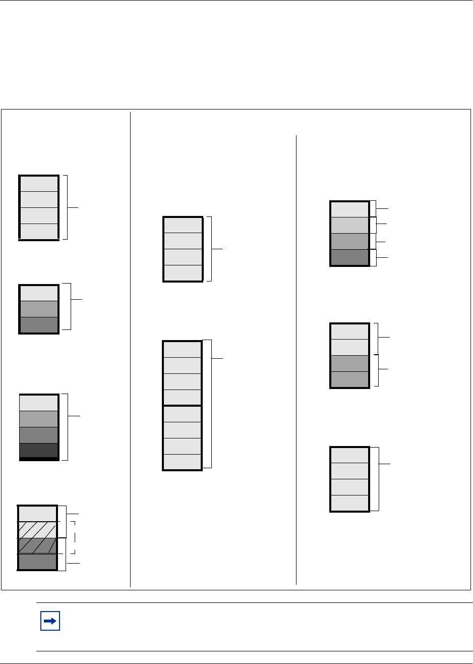
320 Telephony Hardware Selection and Settings
P0993133 03
Determining module channel requirements
Figure 196 shows how much of a DS30 channel each module requires. Note the differences
between modules set to single density and modules set to double density.
Figure 195 Space requirements for media bay modules, on a per-DS30 configuration
Note: If you choose a CTM8, DDIM or a 4X16 module, there are some restrictions about
the offsets you can choose. Refer to the DIP switch settings in “CTM switch settings” on
page 334 and “4X16 switch settings” on page 336 for details
1 DTM
3 BRIs
4 CTMs
CTM8s
per DS30
per DS30
Trunks (lines) Stations (extensions)
per DS30
1 DS30 bus/
offset set to 0
1 DS30 bus/
offset set to 0, 1, or 2
1 DS30 bus/
offset set to 0, 1, 2, or 3
1 DS30 bus/
offset set to 0, 1, or 2
per DS30
max. of
2 offsets
Single-density modules Double-density module
s
4 DD ASM8s
1 DS30 bus/
per DS30
2 DD DSM 16+
per DS30
1 DS30 bus
1 DD DSM 32+
per DS30
1 DS30 bus/
1 DSM 16
per DS30
1 DS30 bus/
offset set to 0
1 DSM 32
per 2 DS30s
2 DS30 buses/
offset set to 0
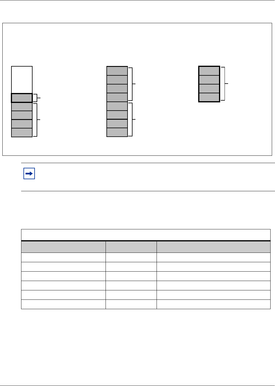
Telephony Hardware Selection and Settings 321
Installation and Maintenance Guide
Figure 196 Space requirements for special media bay modules
1Make a list of modules and the space requirements for each module you chose.
Refer to Table 50.
2Set the bus numbers and offsets on the DIP switches of the module. Refer to Chapter 4,
“Install, remove or replace the Media Bay Modules,” on page 109. Note that you assign trunk
modules starting from the bottom DS30, and you assign station modules starting from the top
DS30.
3Install the modules into the Business Communications Manager or expansion unit. Refer to
Chapter 4, “Install, remove or replace the Media Bay Modules,” on page 109.
4This procedure is complete.
Note: If you choose a CTM8 or a 4X16 module, there are some restrictions about the
offsets you can choose. Refer to the DIP switch settings in “CTM switch settings” on
page 334 and “4X16 switch settings” on page 336 for details
Table 50 Matching modules to DS30 channel capacity
DS30 split 2/6 (default) _____ 3/5 (extra IP lines) _____
Type of module Number required DS30s/offsets required
Combination and specialized media bay modules
Note: The FEM module requires a DS30 bus
for each port that is active. If all ports are
active, no other modules can be added to the
system.
4X16 module
2 DS30 buses/
offset set to 0, 1, 2, or 3
DECT module
1 DS30 bus/
offset set to 0
DDIM module
2 DS30 buses/
offset set to 0
1 offset of
1 full DS30
for lines
1 full DS30
for telephone
and equipment
connections
1 DECT
per DS30
(1 DECT per
system)
1 full DS30
for DTM
module
1 full DS30
for data module

322 Telephony Hardware Selection and Settings
P0993133 03
Set Media Bay Module Dip Switches
Before you install a media bay module, assign switch settings for the media bay module. These
settings determine which line numbers (trunks) or DNs (extensions) the equipment connected to
the module will have access to. The DIP switches are located on the back or underside of the
media bay module.
Start from the list of modules you chose in Chapter 4, “Install, remove or replace the Media Bay
Modules,” on page 109.
After you determine which DS30 buses you want to use, and how much DS30 capacity each
module requires, determine the location of the modules on the DS30 array. From that information,
you choose switch settings for each module. These settings are then set on the module DIP
switches.
This chapter describes the latter process of positioning your modules in the DS30 hierarchy and
determining and setting the DIP switch settings on the module.
Rules for Assigning DS30 Resources
Media bay modules are assigned to DS30 buses in a specific hierarchical manner. This section
describes the preferred order of positioning for each type of module.
Notes about assigning modules
The following are some general notes about assigning modules:
• The DIP switches on the DDIM module are used to set the DS30 designation for the DTM part
of the module. The module automatically assigns an additional DS30 for the data module part
of the DDIM. You cannot choose DS30 7 for the DDIM module, because the data module
would not be accessible. The same applies to DS30 6 if your system is set to a 3/5 split. Refer
to DDIM switch settings on page DDIM switch settings on page 333.
• If you chose a 3/5 channel split for your system, DS30 7 cannot be used by any module. For
modules that require two buses, this means that you cannot set the DIP switches to DS30 6 for
those modules, because the second level of lines would fall into DS30 7, which would not be
accessible. Refer to Figure 197 on page 325.
Refer to “Understanding DS30 numbers” on page 84 for more information about 2/6 and 3/5
DS30 channel splits.
Note: Fiber Expansion Module (FEM) switches
The switches on the fiber expansion module (FEM) do not work in the same way as those
on the other media bay modules. On the FEM, the switches turn the fiber ports on and off.
For information about setting the switches on an FEM, refer to “FEM switch settings” on
page 344.

Telephony Hardware Selection and Settings 323
Installation and Maintenance Guide
• DSM 32 modules require two DS30 numbers. When you assign the first DS30 number to a
DSM 32, the module automatically adds the next DS30 number. For example, if you assign
DS30 2 to an DSM 32, it uses DS30 2 and 3. However, you cannot choose DS30 7 for the
DSM32 module, because the second level of DSM lines would not be accessible. The same
applies to DS30 6 if your system is set to a 3/5 split. Refer to DSM switch settings on page
338.
DSM 32+ modules can be set to either single or double density. When they are set to double
density, the module only requires one DS30 bus.
• The DIP switches on the 4X16 module are used to set the DS30 designation and offset for the
CTM part of the module. The module automatically assigns an additional DS30 for the 16
DSM lines. However, you cannot choose DS30 7 for the 4X16 module, because the DSM lines
would not be accessible. The same applies to DS30 6 if your system is set to a 3/5 split. Refer
to 4X16 switch settings on page 336.
• Companion: configure the DSM or DSMs handling Business Communications Manager
Companion to DS30 DS30 6 or 7. You must change the module number of any trunk media
bay modules configured to module 6 or 7 to an unassigned module number to prevent conflicts
with Companion.
• The CTM8 module, when set to single density, uses two offsets on a DS30 bus. You assign the
first offset to the module, and the second offset is automatically selected. This means that you
can choose offset pairs 0-1, 1-2, or 2-3. Because the module requires two offsets on the same
DS30, you cannot select offset 3. Refer to CTM switch settings on page 334.
When the CTM8 is set to double density, you can install four CTM8s per DS30 bus, using all
four offsets.
• Not all modules are available to all systems. Refer to “Media Bay Module System Selection”
on page 313 for specifics about each module.
Note: Companion DS30 split restrictions:
If you choose a 3/5 channel split for your system, the second module cannot be assigned.
Therefore, you can add a maximum of 16 Companion base stations, which support a
maximum of 30 handsets. This means you can only use a DSM 16 on DS30 6. You cannot
assign a DSM 32.
If your system is set to full double density (FDD), DS30 6 and/or 7 do not support
Companion.
Note: Remember, if you have chosen a 3/5 channel split for your system, DS30 7 is no
longer available for media bay modules.

324 Telephony Hardware Selection and Settings
P0993133 03
Choose the assigned order for modules
Assign the media bay modules and DS30 channels in the order shown in Figure 197.
Station modules are assigned starting with DS30 2. This allows telephones to start numbering from
the system Start DN (Default: 221). The exception to this is a DSM used for Companion, which
must be installed on DS30 6 (DSM32) or DS30 6 and 7 (two DSM 16s). If your system is set to a
3/5 split, you can only assign a DSM16 to DS30 6 for Companion.
Trunk modules are assigned starting at DS30 7, in a system with a 2/6 DS30 split, and at DS30 6 in
a system with a 3/5 split. The exception to this is the 4X16 module and the DDIM, which require
two DS30 buses, so it must be set to a DS30 that has the next channel open.
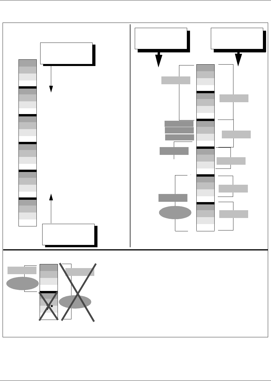
Telephony Hardware Selection and Settings 325
Installation and Maintenance Guide
Figure 197 Assigning single-density modules to the DS30 channel hierarchy
2
3
4
5
6
7*
DS30
buses
DN assignment
begins with Start DN
(default: 221)
Station modules are
assigned starting at the top
(DS30 2) of the available
media bay module DS30
buses.
Exception: DSM 16 or DSM 32
used for Companion. In this
case, DSM 32 must be set to
DS30 6. DSM 16 can be
installed in both DS30 6 and 7.
If DS30 7 is not available you
cannot use a DSM32.
Lines start at 61 on
DS30 7
Trunk modules are
assigned starting with the
last available media bay
module DS30 bus (DS30 6 or
7, depending on the channel
split in effect).
Exception: a 4X16 module or
a DDIM cannot be assigned
to the last DS30 bus.
3/5 channel split
* DS30 7 is not available to any module if your system has been
configured with a 3/5 channel split
Modules that require two DS30 buses, such as the DSM32 and the
4X16, must be assigned to DS30s higher than 6, to allow
accommodate all the resource requirements.
Companion: Only a maximum of 16 Companion base stations
(30 handsets) can be registered on a system configured with a
3/5 split.
2
3
4
5
6
7*
DS30
buses
CTM
4X16
DSM 32
Companion
Example of
North American-
based setup
After you choose your modules, choose where
to assign them on the DS30 buses Example of a
European- based
setup
DSM 32
DSM 16
DS30 5 supports the
station module part of
the 4X16
BRI
6DSM 32
DSM 32
Companion
BRI
DECT
DSM 16
Companion
CTM
CTM
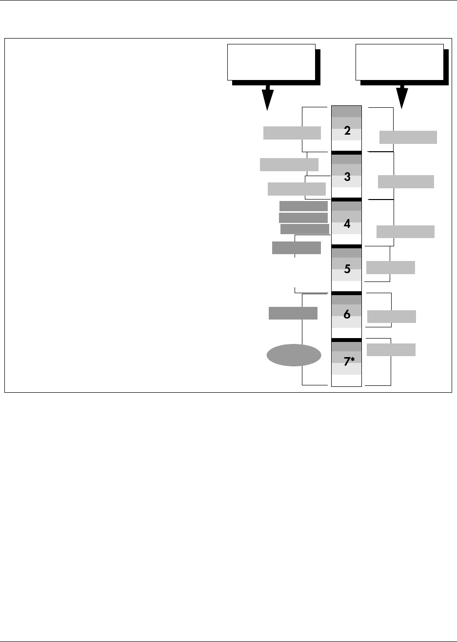
326 Telephony Hardware Selection and Settings
P0993133 03
Figure 198 Assigning double density modules to the DS30 channel hierarchy
Determine module DIP switch settings
After you determine in which order you want to assign the modules, you determine the specific
switch settings for each module.
1Use Table 52 (trunk modules) and Table 53 (station modules) to determine a switch setting for
all modules except the DECT and FEM modules. Figure 199 shows an example of the table
and how to do the following steps:
Step 1: On Table 52 or Table 53 circle the module names.
Step 2: Number the order in which you want to assign the modules.
Step 3: Determine the number of DS30s each module requires. For some station modules
this will depend on whether you choose to set the module to single or double density.
Step 4: Circle the DS30 bus and offset numbers.
Step 5: Follow the DS30 bus and offset number to the far right column where the switch
settings are indicated. Circle the setting for each module.
Partial density
Systems configured with Partial double density (PDD),
allow Companion telephones on DS30 6 and 7 (if the sys-
tem is set to a 2/6 split). In this configuration, DS30 6 and 7
only allow single-density modules. DS30 2 to 5 are set to
allow double density modules.
Double density
Systems configured with Full double density (FDD), do not
allow Companion telephones. All DS30s are set to allow
double density modules.
3/5 channel split
Works in same as shown in the single-density diagram. If
the system is set to a 3/5 split, DS30 7 is not available to
any media bay modules.
DS30
buses
4X16
DD DSM 32+
Example of
North American-
based setup
Example of a
European- based
setup
DD DSM 32+
DS30 5 supports
the station module
part of the 4X16
BRI
SD DSM 32
Companion
BRI
DECT
DD DSM 32+
DD DSM 32+
Double-density example
(system configured as Partial Density)
DD DSM 16+
DD DSM 16+
CTM
CTM
CTM
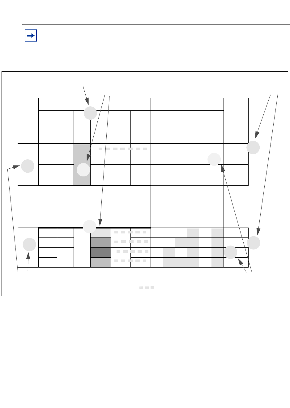
Telephony Hardware Selection and Settings 327
Installation and Maintenance Guide
Figure 199 How to use the configuration map
Example: Position your DSM 32 module (step 1), which requires two full DS30 buses (step 2), in
DS30 2 and 3 (step 3). Moving across, note that the offset is 0 (step 4). Set the DIP switches on the
module to match the DIP switch settings indicated for that offset (step 5).
Note: If you must assign specific line or extension numbers to a module, refer to the
individual switch tables in “Line and extension numbers for specific modules” on
page 332 for line and DN listings.
DS30
bus #
Media bay module positioning DIP switch setting
Off-set
4x16 ASM
8DTM CTM CTM 8 BRI
123
(offset) 456
(DS30 ch)
2on on on on on on 0
7on on on off on off 0
on on off off on off 1
on off on off on off 2
on off off off on off 3
1. Indicate the modules you want to install
2. Note how many DS30 buses each module requires
3. Choose the DS30 numbers to
assign to the modules
4. Assign an offset
number to each module
5. Make a note of the DIP switch settings for the DS30/offset numbers
1
2
3
4
5
5
DIP switch setting for offset
2
3
4

328 Telephony Hardware Selection and Settings
P0993133 03
Table 52 shows possible DS30 and offset configurations for each type of trunk module, and the
corresponding switch settings. For DECT and FEM settings, refer to “DECT switch settings” on
page 343 and “FEM switch settings” on page 344.
Table 52 Possible trunk media bay module DIP switch settings
DS30
bus #
Media bay module positioning (trunk modules) DIP switch settings
Offsets
4x16
Offsets
0,1, 2, 3
Line Exten.
DDIM
Offsets
0
DTM
Offset
s 0
CTM
Offsets
0, 1, 2, 3
CTM 8
Offsets
0, 1, 2
BRI
Offsets
0, 1, 2, 3 12 3
(offset) 45 6
(DS30 ch)
2
0Picks
up
ch. #3
0 Picks up
ch. #3 0 0 0 0 on on on on on on 0
1 1 1 1 on on off on on on 1
2 2 2 2 on off on on on on 2
3 3 on off off on on on 3
3
0Picks
up
ch. #4
0 Picks up
ch. #4 0 0 0 0 on on on on on off 0
1 1 1 1 on on off on on off 1
2 2 2 2 on off on on on off 2
3 3 on off off on on off 3
4
0Picks
up
ch. #5
0 Picks up
ch. #5 0 0 0 0 on on on on off on 0
1 1 1 1 on on off on off on 1
2 2 2 2 on off on on off on 2
3 3 on off off on off on 3
5
0Picks
up
ch. #6
0 Picks up
ch. #6 0 0 0 0 on on on on off off 0
1 1 1 1 on on off on off off 1
2 2 2 2 on off on on off off 2
3 3 on off off on off off 3
6
0Picks
up
ch. #7
0 Picks up
ch. #7 0 0 0 0 on on on off on on 0
1 1 1 1 on on off off on on 1
2 2 2 2 on off on off on on 2
3 3 on off off off on on 3
7*** Not supported Not supported
0 0 0 0 on on on off on off 0
1 1 1 on on off off on off 1
2 2 2 on off on off on off 2
3 on off off off on off 3
Module set to offset 0 Module set to offset 1 Module set to offset 2 Module set to offset 3
Each shaded square represents the amount of the DS30 channel, and the offset, which the module requires.
***If your system is configured with a 3/5 DS30 channel split, DS30 channel 7 is not available to media bay modules
and DS30 channel 6 is not supported for the 4X16 and DDIM modules.
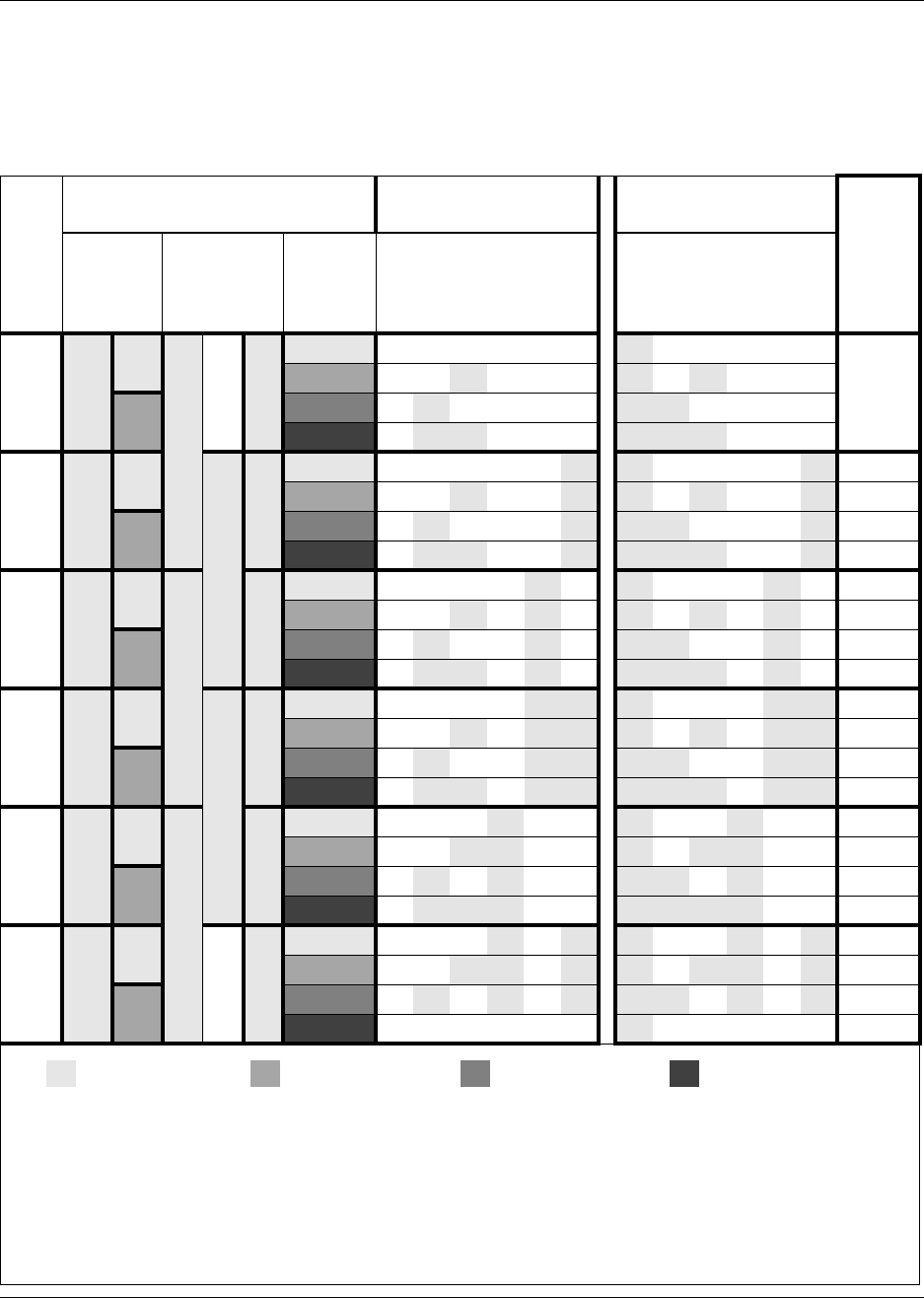
Telephony Hardware Selection and Settings 329
Installation and Maintenance Guide
Table 53 shows possible DS30 and offset configurations for each type of station module, and the
corresponding switch settings. Note that offset 1 indicates the density mode for DSM 16+ and
DSM 32+ modules (SDD = single density, offset 1:on; FDD = Full Double Density, offset 1:off).
Table 53 Possible station media bay module DIP switch settings
DS30
bus #
Media bay module positioning
(station modules) DIP switch settings
(Single density)
DIP switch settings
(Double density)
Offsets
DSM 16+
Offsets 0, 1
SDD
FDD
DSM 32+
Offsets 0, 1
SDD FDD
ASM 8
Offsets 0,
1, 2, 3 12 3 456
(offset) (DS30)
DSM 16+ and DSM 32+
only***
12 3 456
(offset) (DS30)
2
0 0 0 0 0*** on on on on on on off on on on on on 0
1on on off on on on off on off on on on 1
1 2 on off on on on on off off on on on on 2
3on off off on on on off off off on on on 3
3
0 0 0 0 0 on on on on on off off on on on on off 0
1on on off on on off off on off on on off 1
1 2 on off on on on off off off on on on off 2
3on off off on on off off off off on on off 3
4
0 0 0 0 0 on on on on off on off on on on off on 0
1on on off on off on off on off on off on 1
1 2 on off on on off on off off on on off on 2
3on off off on off on off off off on off on 3
5
0 0 0 0 0 on on on on off off off on on on off off 0
1on on off on off off off on off on off off 1
1 2 on off on on off off off off on on off off 2
3on off off on off off off off off on off off 3
6*
0 0 0 0 0 on on on off on on off on on off on on 0
1on on off off on on off on off off on on 1
12**** on off on off on on off off on off on on 2
3*** on off off off on on off off off off on on 3
7**
0 0 0 0 on on on off on off off on on off on off 0
1on on off off on off off on off off on off 1
12**** on off on off on off off off on off on off 2
3*** on off off off on off off off off off on off 3
Module set to offset 0 Module set to offset 1 Module set to offset 2 Module set to offset 3
Each shaded square represents the amount of the DS30 bus, and the offset, which the module requires.
*If your system is configured for Partial double density (PDD), DS30 6 will support only modules set to single density
(SDD) and it supports Companion.
**If your system is configured with a 3/5 DS30 split, DS30 7 is not available to media bay modules.
If your system is configured for PDD and a 2/6 DS30 split, DS30 7 will support only single-density modules, but it will
also support Companion. (Note: DSM 32/DSM 32+ (set to single density) modules cannot be deployed on this bus.)
***ASM modules always use the single density dip switch settings, with the appropriate offset.
****If your system is set to PDD, offsets 2 and 3 are not available to ASM8 modules.
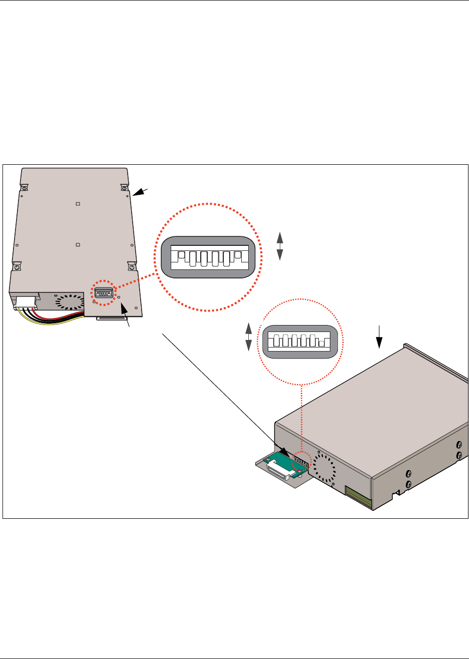
330 Telephony Hardware Selection and Settings
P0993133 03
Set the media bay module DIP switches
Before you install the media bay modules into the Business Communications Manager housing,
you need to set the DIP switches. Make a note of these settings either on the chart shown in Table
52 on page 328 or in the Programming Record forms.
Follow these steps to set the DIP switches:
1Locate the DIP switches on the module.
Figure 200 Switches on the media bay module
2Set the switches to correspond with the settings you chose “Determine module DIP switch
settings” on page 326.
3Repeat for each media bay module you want to install.
6543 21 Off
On
Underside of the
media bay module
DIP switches
Back of the media bay module
123456
On
Off
Rear view of the media bay module
Module is
right-side up

Telephony Hardware Selection and Settings 331
Installation and Maintenance Guide
4You are now ready to install the modules into the Business Communications Manager base or
expansion units. Refer to Chapter 14, “Install Optional Telephony Equipment,” on page 287
for details.
5This procedure is complete.
Tip: Create a label with the DS30 bus and DIP switch settings, and stick it to the front of
the module to provide ease of reference for maintenance activities.
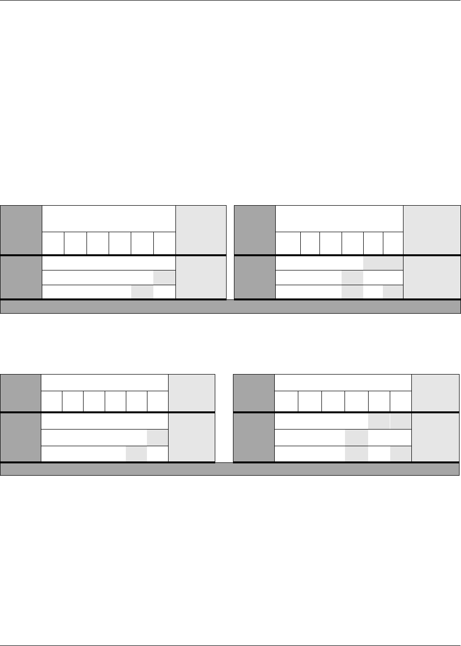
332 Telephony Hardware Selection and Settings
P0993133 03
Line and extension numbers for specific modules
The switch settings on the media bay module determine the line numbers and extension numbers
the modules use. The tables in this section show the correspondence between DS30 numbers,
switch settings, and the line/extension numbers for each type of module. The DS30 number and
switch settings correspond with Table 52 on page 328.
DTM switch settings
Although DTMs have more than 16 lines, they occupy only one DS30 bus per DTM.
Table 54 shows the switch settings for each DS30 bus, and the resulting line assignments.
Table 55 shows the switch settings for each DS30 bus, and the resulting line assignments.
Table 54 DTM switch settings (T1)
Select
DS30
bus
Enter these switch settings To
assign
these
lines
Select
DS30
bus
Enter these switch
settings To assign
these lines
123456 123456
2on on on on on on 211-234 5on on on on off off 121-144
3on on on on on off 181-204 6on on on off on on 91-114
4on on on on off on 151-174 ***7 on on on off on off 61-84
***If your system is configured with a 3/5 DS30 channel split, DS30 7 is not available.
Table 55 DTM switch settings (North American PRI)
Select
DS30
bus
Enter these switch settings To assign
these
lines
Select
DS30
bus
Enter these switch settings To assign
these
lines
123456 1 2 3 456
2on on on on on on 211-233 5on on on on off off 121-143
3on on on on on off 181-203 6on on on off on on 91-113
4on on on on off on 151-173 ***7 on on on off on off 61-83
***If your system is configured with a 3/5 DS30 channel split, DS30 7 is not available.
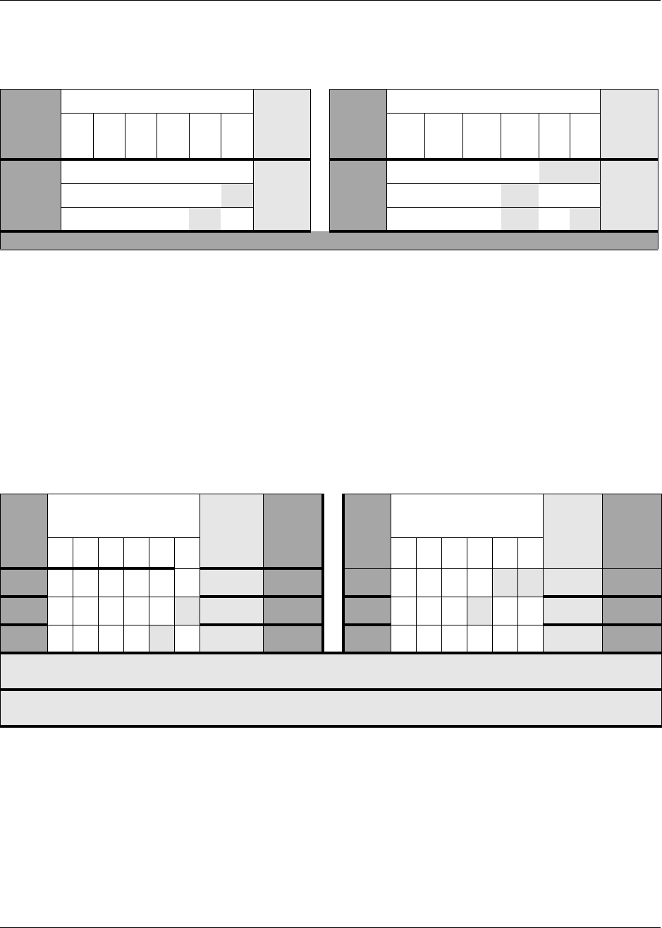
Telephony Hardware Selection and Settings 333
Installation and Maintenance Guide
Table 56 shows the switch settings for each DS30 bus, and the resulting line assignments.
DDIM switch settings
The DDIM module combines a DTM and a Data Module. The switch setting you choose
determines the DS30 channel assigned to the DTM portion of the DDIM. The Data Module is
automatically assigned the next DS30 channel number.
The DS30 channel you assign to the DDIM determines the line numbers of the T1 line connected
to the DDIM. Table 54 shows the switch settings for each DS30 channel, and the resulting line
assignments.
Table 56 DTM switch settings (E1 and UK PRI)
Select
DS30
bus
Enter these switch settings To
assign
these
lines
Select
DS30
bus
Enter these switch settings To
assign
these
lines
123456 123456
2on on on on on on 211-240 5on on on on off off 121-150
3on on on on on off 181-210 6on on on off on on 91-120
4on on on on off on 151-180 ***7 on on on off on off 61-90
***If your system is configured with a 3/5 DS30 channel split, DS30 channel 7 is not available.
Table 57 DDIM switch settings
Select
DS30
bus
Enter these switch
settings To
assign
these
lines
Data
Module
DS30
channel
Select
DS30
bus
Enter these switch
settings To
assign
these
lines
Data
Module
DS30
channel123456 123456
2on on on on on on 211-234 3 5 on on on on off off 121-144 6
3on on on on on off 181-204 4 6 on on on off on on 91-114 7*
4on on on on off on 151-174 5 7 **
* If your system is configured with a 3/5 DS30 channel split, you cannot use DS30 channel 6 for the DDIM. When you
use a 3/5 split, DS30 channel 7 is not available for the data module portion of the DDIM.
** You cannot use DS30 channel 7 for the DDIM. If you assign DS30 channel 7, there is no DS30 channel available for
the data module portion of the DDIM.
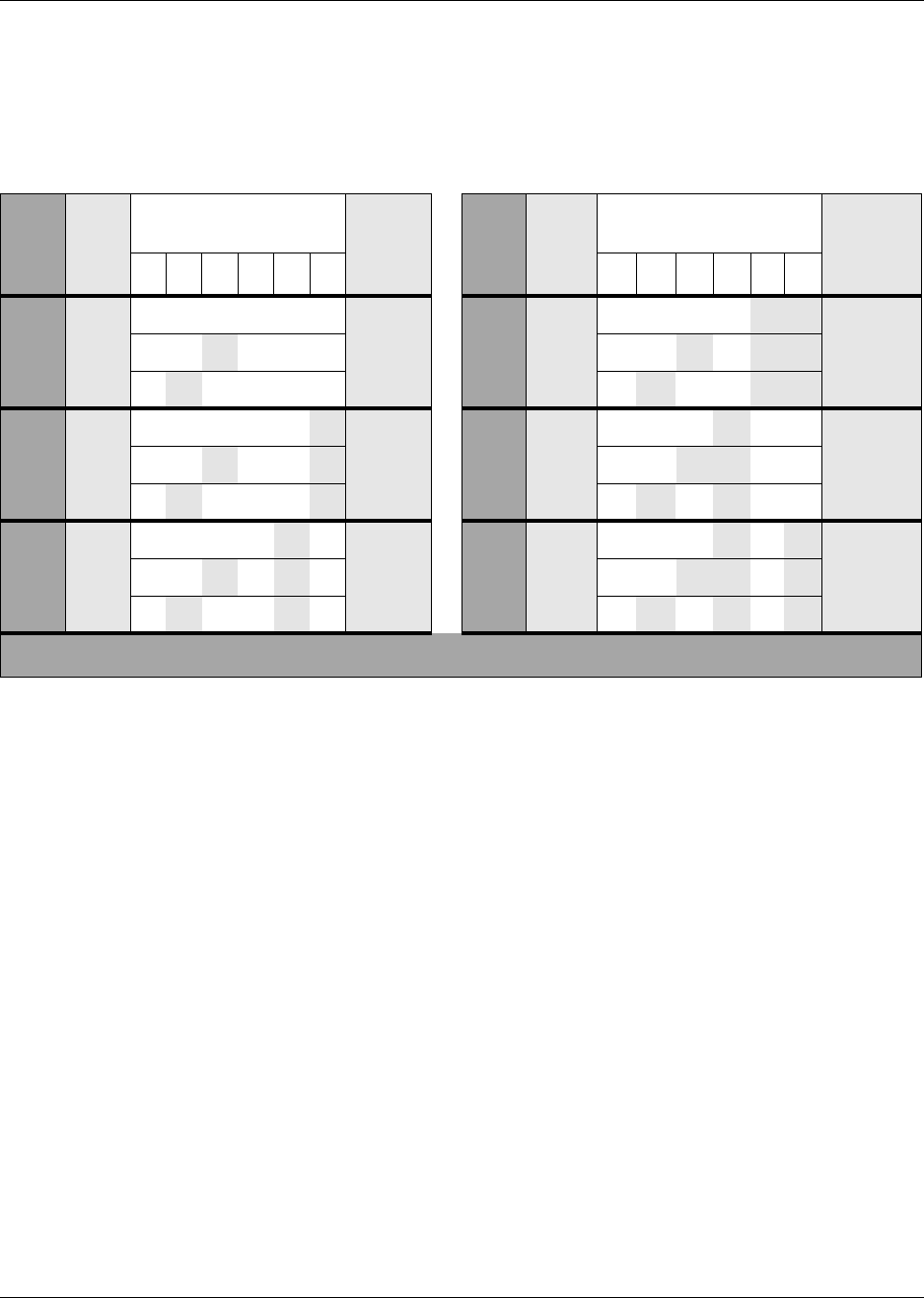
334 Telephony Hardware Selection and Settings
P0993133 03
BRI switch settings
You can install a maximum of three BRI modules per DS30 bus on the offsets indicated below.
Table 58 shows the switch settings for each DS30 number, and the resulting line assignments.
CTM switch settings
There are two models of CTMs.
• CTMs have four lines, therefore, you can add a maximum of four CTMs per DS30 bus.
• CTM8s have eight lines. This module uses two offset settings per module. Therefore, you can
add a maximum of two CTM8 modules per DS30 bus.
• You can also mix the two modules. For instance, if you have two existing CTM modules with
offset 0 and 1, you can add a CTM8 on offset 2.
CTM: The CTM provides connections for four analog calling line identification (CLID) PSTN
lines. Each voice line uses one line in the offset. Since each DS30 channel has four lines per offset,
you can assign a maximum of four CTMs to a single DS30 bus by making the offset switch
settings different for each module. You can also combine three CTMs with the trunk module part
of the 4X16 module on the same DS30 bus.
CTM8: The CTM8 provides connections for eight analog calling line identification (CLID) PSTN
lines. Each line uses one voice line. Since each DS30 bus has four lines per offset, you require two
offsets for each module. You can assign a maximum of two CTM8s to a DS30 bus, by making the
offset switch settings different for each module.
Table 58 BRIM S/T switch settings
Select
DS30
bus
Select
offset
Enter these switch
settings To
assign
these
lines
Select
DS30
bus
Select
offset
Enter these switch
settings To assign
these
lines
123456 1 23456
2 0 on on on on on on 211-218 5 0 on on on on off off 121-128
1on on off on on on 219-226 1on on off on off off 129-136
2on off on on on on 227-234 2on off on on off off 137-144
3 0 on on on on on off 181-188 6 0 on on on off on on 91-98
1on on off on on off 189-196 1on on off off on on 99-106
2on off on on on off 197-204 2on off on off on on 107-114
4 0 on on on on off on 151-158 ***7 0on on on off on off 61-68
1on on off on off on 159-166 1on on off off on off 69-76
2on off on on off on 167-174 2on off on off on off 77-84
***If your system is configured with a 3/5 DS30 channel split, DS30 channel 7 is not available.

Telephony Hardware Selection and Settings 335
Installation and Maintenance Guide
You can also combine a CTM8 with a 4X16 module on the same DS30 number.
When you choose an offset number for the CTM8, the system automatically adds the next offset
number. You cannot assign offset 3 to the CTM8 module, because this does not allow the module
to assign the second set of lines.
Table 59 shows the switch settings for each DS30 number, and the resulting line assignments for
CTMs and CTM8s.
Table 59 CTM and CTM8 switch settings
Select
DS30
bus
Select
offset Enter these switch settings To assign these
lines
To assign these lines.
CTM8
123456 CTM Lower
(Lines 1-4) Upper
(lines 5-8)
2
0on on on on on on 211-214 211-214 219-222
1on on off on on on 219-222 219-222 227-230
2on off on on on on 227-230 227-230 235-238
3on off off on on on 235-238 Not supported Not supported
3
0on on on on on off 181-184 181-184 189-192
1on on off on on off 189-192 189-192 197-200
2on off on on on off 197-200 197-200 205-208
3on off off on on off 205-208 Not supported Not supported
4
0on on on on off on 151-154 151-154 159-162
1on on off on off on 159-162 159-162 167-170
2on off on on off on 167-170 167-170 175-178
3on off off on off on 175-178 Not supported Not supported
5
0on on on on off off 121-124 121-124 129-132
1on on off on off off 129-132 129-132 137-140
2on off on on off off 137-140 137-140 145-148
3on off off on off off 145-148 Not supported Not supported
6
0on on on off on on 91-94 91-94 99-102
1on on off off on on 99-102 99-102 107-110
2on off on off on on 107-110 107-110 115-118
3on off off off on on 115-118 Not supported Not supported
***7
0on on on off on off 61-64 61-64 69-72
1on on off off on off 69-72 69-72 77-80
2on off on off on off 77-80 77-80 85-88
3on off off off on off 85-88 Not supported Not supported
***If your system is configured with a 3/5 DS30 channel split, DS30 channel 7 is not available.
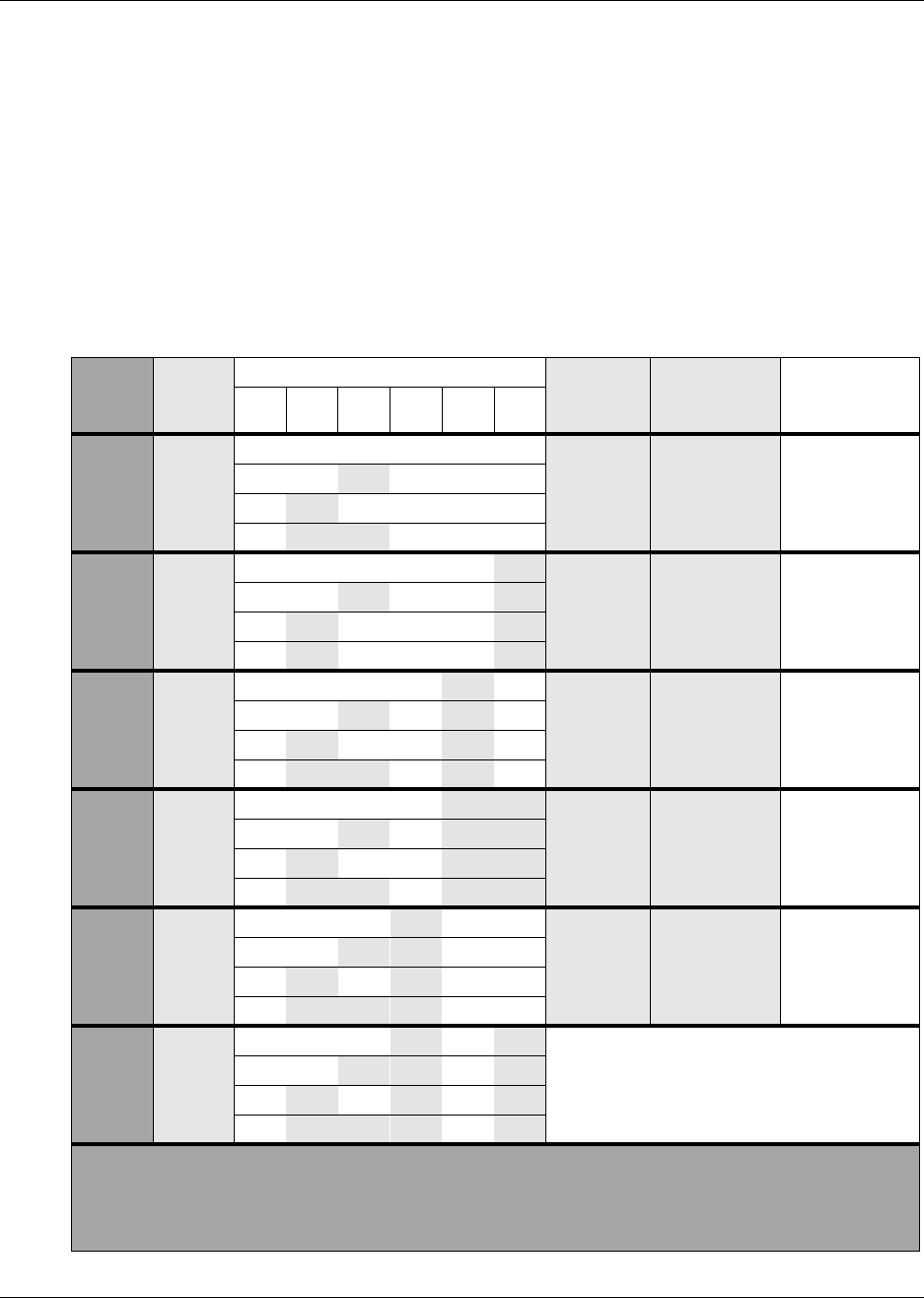
336 Telephony Hardware Selection and Settings
P0993133 03
4X16 switch settings
The 4X16 module combines a CTM and a DSM 16. The CTM only requires four lines on the
DS30 bus. Therefore, it can be assigned any of the four offsets in a DS30 bus. The DSM module
then automatically assigns the next DS30 number and all the assigned DNs.
This module can be combined with three other CTMs or one CTM8 on the same DS30 bus.
Table 60 shows the switch settings for each DS30 bus, and the assigned lines and dialing numbers
(DNs) for each DS30 bus.
Table 60 4X16 switch settings
Select
DS30
bus
Select
offset
Enter these switch settings To assign
these
lines
And this
DS30 and
DNs
**Custom DN
range
123456
2
0on on on on on on 211-214
DS30 3
237-252
1on on off on on on 219-222
2on off on on on on 227-230
3on off off on on on 235-238
3
0on on on on on off 181-184
DS30 4
253-268
1on on off on on off 189-192
2on off on on on off 197-200
3on off on on off 205-208
4
0on on on on off on 151-154
DS30 5
269-284
1on on off on off on 159-162
2on off on on off on 167-170
3on off off on off on 175-178
5
0on on on on off off 121-124
DS30 6
285-300
1on on off on off off 129-132
2on off on on off off 137-140
3on off off on off off 145-148
6
0on on on off on on 91-94
DS30 7***
301-316
1on on off off on on 99-102
2on off on off on on 107-110
3on off off off on on 115-118
***7
on on on off on off
Not supported
on on off off on off
on off on off on off
on off off off on off
** The extensions listed are based on a three-digit DN with a Start DN of 221. If your system has longer
DNs or a different Start DN, enter the range in the blank column.
*** If your system is configured with a 3/5 DS30 channel split, you cannot configure this module for DS30 6
since DS30 7 is not available for the second level.
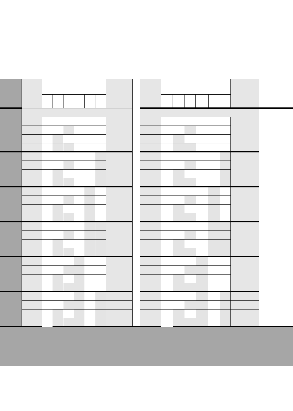
Telephony Hardware Selection and Settings 337
Installation and Maintenance Guide
ASM 8 switch settings
In a single density configuration, such as for DS30 6 or 7 when they are set to the default PDD,
only offset 1 and 2 are available to ASM8s. In a double-density configuration, you can install four
ASM8s per DS30 bus. Table 61 shows the switch settings for each DS30 number and the dialing
numbers (DNs) assigned to each DS30 number.
Table 61 ASM8 settings for upgraded 2.5 systems and new 3.0 systems
Select
bus Select
offset Enter these switch
settings To
assign
these
DNs
Select
offset Enter these switch
settings To
assign
these
DNs
**Custom
DN range
123456 1 23 4 56
2.5 system upgraded to 3.0 New 3.0 system
2
0on on on on on on 221-228 0on on on on on on 221-228
1on on off on on on 228-236 1on on off on on on 228-236
2on off on on on on 377-384 2on off on on on on 237-244
3on off off on on on 385-392 3on off off on on on 245-252
3
0on on on on on off 237-244 0on on on on on off 253-260
1on on off on on off 245-252 1on on off on on off 261-268
2on off on on on off 393-400 2on off on on on off 269-275
3on off off on on off 401-408 3on off off on on off 276-284
4
0on on on on off on 253-260 0on on on on off on 285-292
1on on off on off on 261-268 1on on off on off on 293-300
2on off on on off on 409-416 2on off on on off on 301-308
3on off off on off on 417-424 3on off off on off on 309-316
5
0on on on on off off 269-276 0on on on on off off 317-324
1on on off on off off 277-284 1on on off on off off 325-332
2on off on on off off 425-432 2on off on on off off 333-340
3on off off on off off 433-440 3on off off on off off 341-348
6
0on on on off on on 285-292 0on on on off on on 349-356
1on on off off on on 293-300 1on on off off on on 357-364
****2 on off on off on on 441-448 ****2 on off on off on on 365-372
****3 on off off off on on 449-456 ****3 on off off off on on 373-380
7*** 0on on on off on off 301-308 0on on on off on off 381-388
1on on off off on off 309-316 1on on off off on off 389-396
*****2 on off on off on off 457-454 *****2 on off on off on off 397-404
*****3 on off off off on off 455-472 *****3 on off off off on off 405-412
** The extensions listed are based on a three-digit DN with a Start DN of 221. If your system has longer DNs or a
different Start DN, enter the range in the blank column.
*** If your system is configured with a 3/5 channel split, DS30 7 is not available.
****Available only on systems set to FDD.
*****Available only on systems set to FDD, with a 2/6 DS30 split.

338 Telephony Hardware Selection and Settings
P0993133 03
DSM switch settings
There are two types of DSMs:
• DSM 16s have one connector which connects to 16 lines (telephones). These modules require
a full DS30 number each (single density), or half a bus (double density).
• DSM32s have two connectors, each of which connects to 16 lines (telephones). These
modules require two full, consecutive DS30 numbers (single density) or one full bus (double
density).
This section includes these charts:
•“DSM16/DSM 32 single density switch settings (upgraded system)” on page 338
•“DSM16+ and DSM 32+ double density switch settings (upgraded system)” on page 340
•“DSM16/DSM 32 single density switch settings (new 3.0 system)” on page 341
•“DSM16+ and DSM 32+ double density switch settings (new 3.0 system)” on page 342
DSM16/DSM 32 single density switch settings (upgraded system)
The following table shows the switch settings for DSM modules deployed as single density on a
system that has been upgraded from 2.5 to 3.0. For single-density modules, you set the first DS30
number on the DIP switches, and the system assigns the next DS30 bus. Note in Table 62 how the
DSM32 module spans two DS30 bus numbers and that there are only five possible DS30 settings
for the DIP switches.
Note that Companion sets can only be assigned on DS30 6 and 7, and the handsets have a different
set of default DNs than the digital sets. Also, Companion can only be deployed on systems that
remain at Part Double Density (PDD), the default condition of 3.0 systems.
Note: DSM modules deployed with 2.5 systems are all single density and cannot be set to
double density. The DSM 16+ and DSM32+ modules can be set to either density.
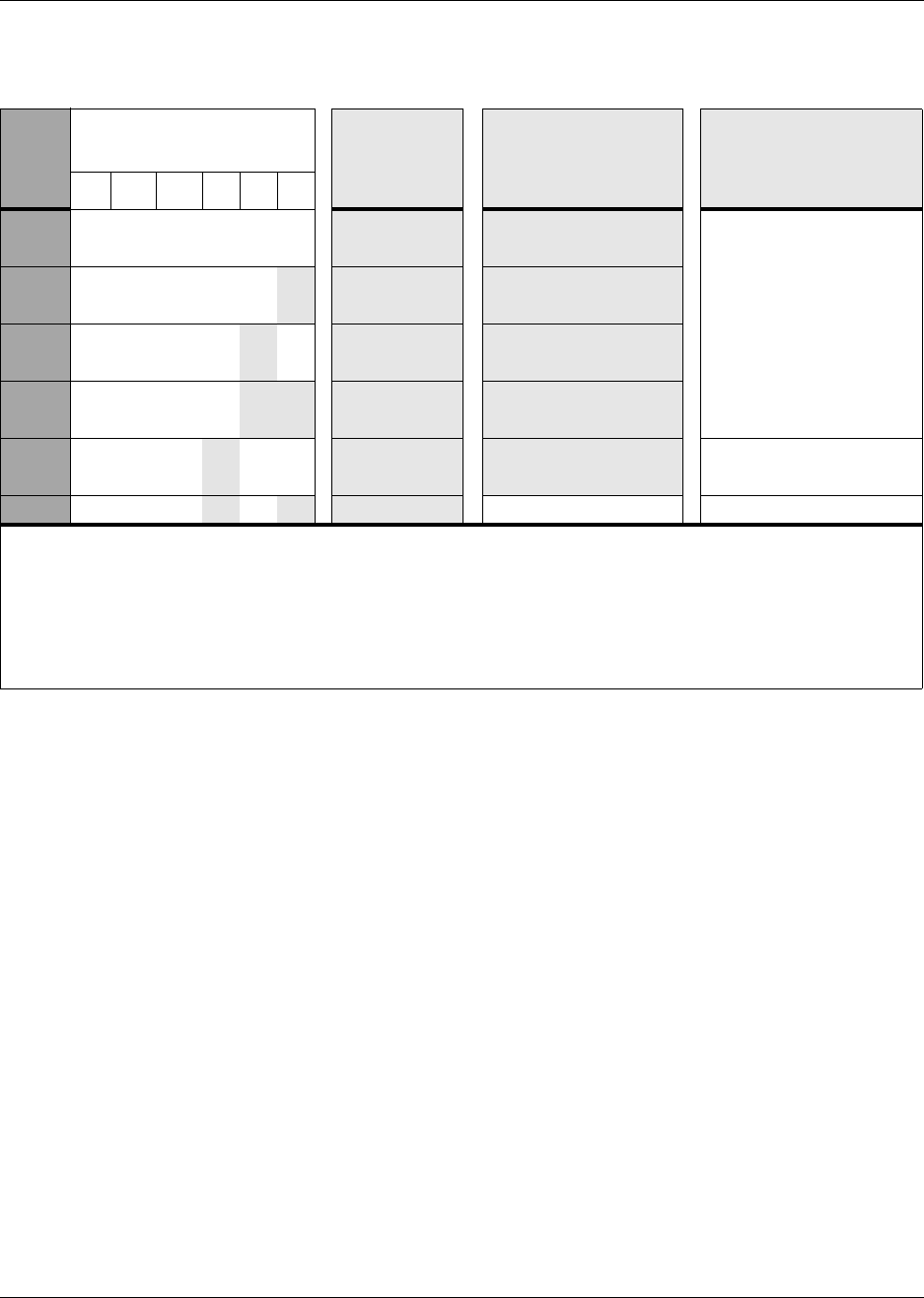
Telephony Hardware Selection and Settings 339
Installation and Maintenance Guide
Table 62 DSM 16/DSM 16+ and DSM 32/DSM32+ single density switch settings for 2.5 systems
upgraded to 3.0
Select
DS30
bus
Enter these switch
settings
**To assign
these DNs
to DSM16 or
DSM 16+
To assign these
DNs to DSM 32 or
DSM 32+
To assign these DNs
to Companion
123456
2on on on on on on 221-236 221-252
(DS30 2 and 3)
N/A
3on on on on on off 237-252 237-268
(DS30 3 and 4)
4on on on on off on 253-268 253-284)
(DS30 4 and 5)
5on on on on off off 269-284 269-300
(DS30 5 and 6)
6on on on off on on 285-300 285-316
(DS30 6 and 7) 565-580**** (PDD only)
***7 on on on off on off 301-316 N/A 581-596**** (PDD only)
**The extensions listed are based on a three-digit DN with a Start DN of 221. If your system has longer DNs or a
different Start DN, enter the range in the blank column.
***If your system is configured with a 3/5 DS30 channel split, you cannot use DS30 7 for the DSM 16 module. You
cannot configure the DSM 32 module for DS30 6 because the second set of DNs cannot be accessed.
****If you need more DNs for Companion sets, use the range that starts at 597 (ISDN or DECT) and change the
DN type to NA Portable.
*****If you system is set to Full Double Density (FDD), Companion telephones are not supported.
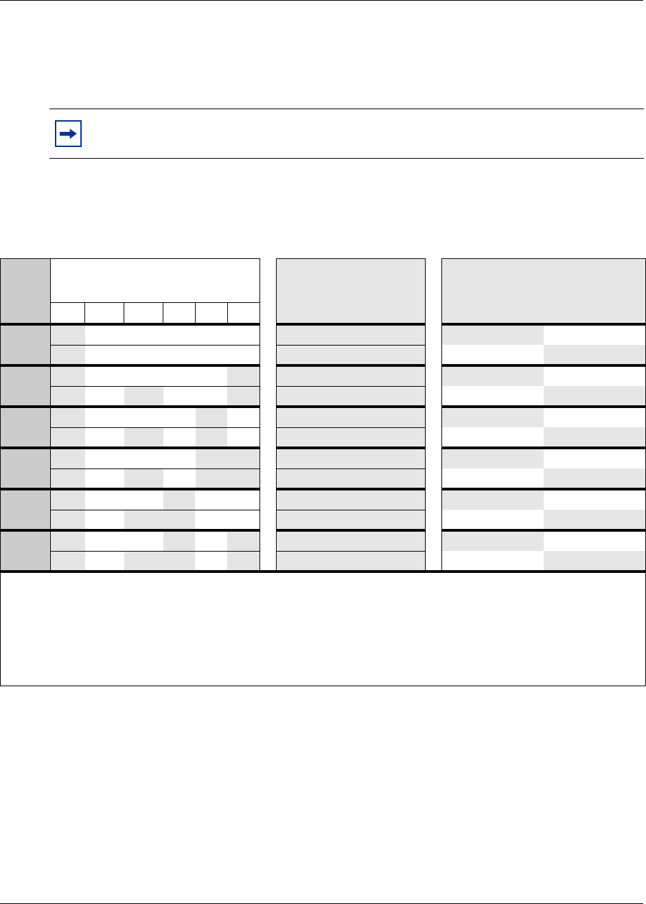
340 Telephony Hardware Selection and Settings
P0993133 03
DSM16+ and DSM 32+ double density switch settings (upgraded system)
The following table shows the switch settings for DSM-plus modules deployed as double density
on a system that has been upgraded from 2.5 to 3.0.
Companion has not be included in this table because you cannot use modules set to double density
to deploy Companion.
Note: DSM modules deployed with 2.5 systems are all single density and cannot be set to
double density. The DSM 16+ and DSM32+ modules can be set to either density.
Table 63 DSM 16+ and DSM32+ double density switch settings for 2.5 systems upgraded to 3.0
Select
DS30
bus
Enter these switch settings **To assign these
DNs to DSM 16+:
(A= DSM1, B=DSM2)
To assign these DNs to
DSM 32+
(connectors: A=top, B = bottom)
1 2 3 456
2off on on on on on A 221-236 A 377-392
off on off on on on B 377-392 B 221-236
3off on on on on off A 237-252 A 393-408
off on off on on off B 393-408 B 237-252
4off on on on off on A 253-268 A 409-424
off on off on off on B 409-424 B 253-268
5off on on on off off A 269-284 A 425-440
off on off on off off B 425-440 B 269-284
6off on on off on on A 285-300 A 441-456****
off on off off on on B 441-456**** B 285-300
***7 off on on off on off A 301-316 A 457-472*****
off on off off on off B 457-472***** B 301-316*****
**The extensions listed are based on a three-digit DN with a Start DN of 221. If your system has longer DNs or a
different Start DN, enter the range in the blank column.
***If your system is configured with a 3/5 channel split, you cannot use DS30 7 for the DSM 16 module.
****Available only on systems set to FDD. Modules cannot be set to double density on systems set to PDD. Refer to
the previous chart for the switch settings for single density and PDD.
*****Available only on systems set to FDD, with a 2/6 DS30 split. Modules cannot be set to double density on systems
set to PDD. Refer to the previous chart for the switch settings for single density and PDD.
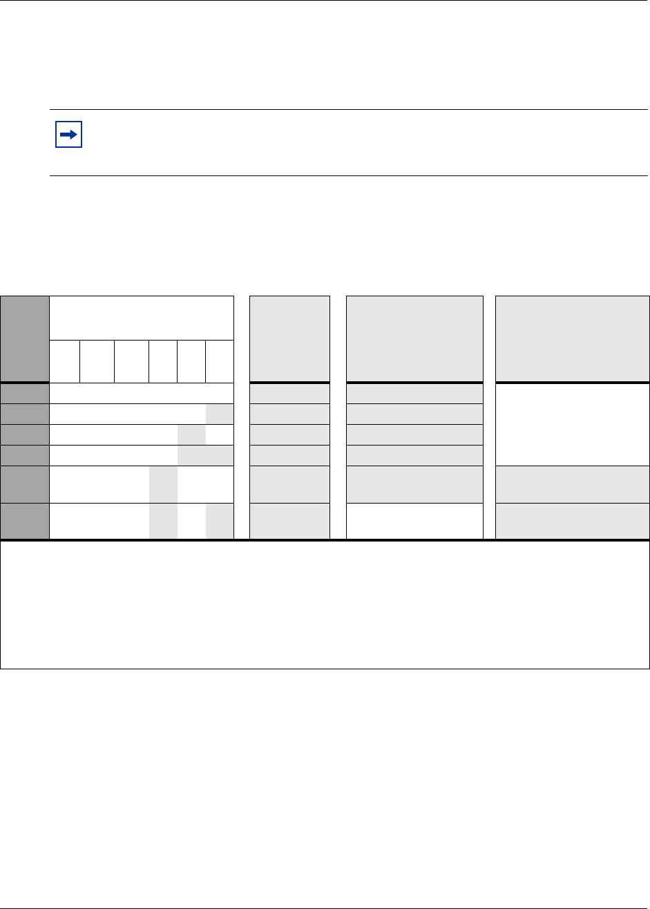
Telephony Hardware Selection and Settings 341
Installation and Maintenance Guide
DSM16/DSM 32 single density switch settings (new 3.0 system)
The following table shows the switch settings for DSM modules deployed as single density on a
new 3.0 system.
Note that Companion sets can only be assigned on DS30 6 and 7, and the handsets have a different
set of default DNs than the digital sets. Also, Companion can only be deployed on systems that
remain at Part Double Density (PDD), the default condition of 3.0 systems.
Note: DSM modules deployed prior to 3.0 are all single density and cannot be set to
double density, but they can still be used on new 3.0 systems. The DSM 16+ and DSM32+
modules can be set to either density.
Table 64 DSM 16/DSM 16+ and DSM 32/DSM32+ single density switch settings for new 3.0 systems
Select
DS30
bus
Enter these switch
settings
**To
assign
these DNs
to DSM 16
or DSM 16+
To assign these
DNs to DSM 32 or
DSM 32+
Top Bottom
To assign these DNs
to Companion
1 2 3 456
2on on on on on on 221-236 253-268 221-236
N/A
3on on on on on off 253-268 285-300 253-268
4on on on on off on 285-300 317-332 285-300
5on on on on off off 317-332 349-364 317-332
6on on on off on on 349-364 381-396 349-364 565-580**** (PDD
only)
***7 on on on off on off 381-396 N/A 581-596**** (PDD
only)
**The extensions listed are based on a three-digit DN with a Start DN of 221. If your system has longer DNs or a
different Start DN, enter the range in the blank column.
***If your system is configured with a 3/5 channel split, you cannot use DS30 7 for the DSM 16 module. You cannot
configure the DSM32 module for DS30 6 because the second set of DNs cannot be accessed.
****If you need more DNs for Companion sets, use the range that starts at 597 (ISDN or DECT) and change the
DN type to NA Portable.
*****If you system is set to Full Double Density (FDD), Companion telephones are not supported.
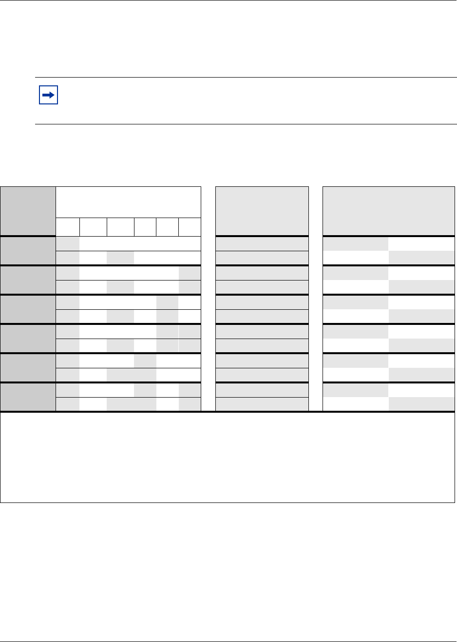
342 Telephony Hardware Selection and Settings
P0993133 03
DSM16+ and DSM 32+ double density switch settings (new 3.0 system)
The following table shows the switch settings for DSM-plus modules deployed as double density
on a new 3.0 system.
Companion has not be included in this table because you cannot use double density modules to
deploy Companion.
Note: DSM modules deployed prior to 3.0 are all single density and cannot be set to
double density, but they can still be used on new 3.0 systems. The DSM 16+ and DSM32+
modules can be set to either density.
Table 65 DSM 16+ and DSM32+ double density switch settings for new 3.0 systems
Select
DS30 bus
Enter these switch settings To assign these
DNs
to DSM 16+:
A= DSM1, B=DSM2
To assign these DNs to
DSM 32+ (connectors:
A=top, B = bottom)
123456
2off on on on on on A 221-236 A 237-252
off on off on on on B 237-252 B 221-236
3off on on on on off A 253-268 A 269-284
off on off on on off B 269-284 B 253-268
4off on on on off on A 285-300 A 301-316
off on off on off on B 301-316 B 285-300
5off on on on off off A 317-332 A 333-348
off on off on off off B 333-348 B 317-332
6off on on off on on A 349-364 A 365-380****
off on off off on on B 365-380**** B 349-364
***7 off on on off on off A 381-396 A 397-412*****
off on off off on off B 397-412***** B 381-396
**The extensions listed are based on a three-digit DN with a Start DN of 221. If your system has longer DNs or a
different Start DN, enter the range in the blank column.
***If your system is configured with a 3/5 channel split, you cannot use DS30 7.
****Available only on systems set to FDD. Modules cannot be set to double density on systems set to PDD. Refer to
the previous chart for the switch settings for single density and PDD.
*****Available only on systems set to FDD, with a 2/6 DS30 split. Modules cannot be set to double density on
systems set to PDD. Refer to the previous chart for the switch settings for single density and PDD.
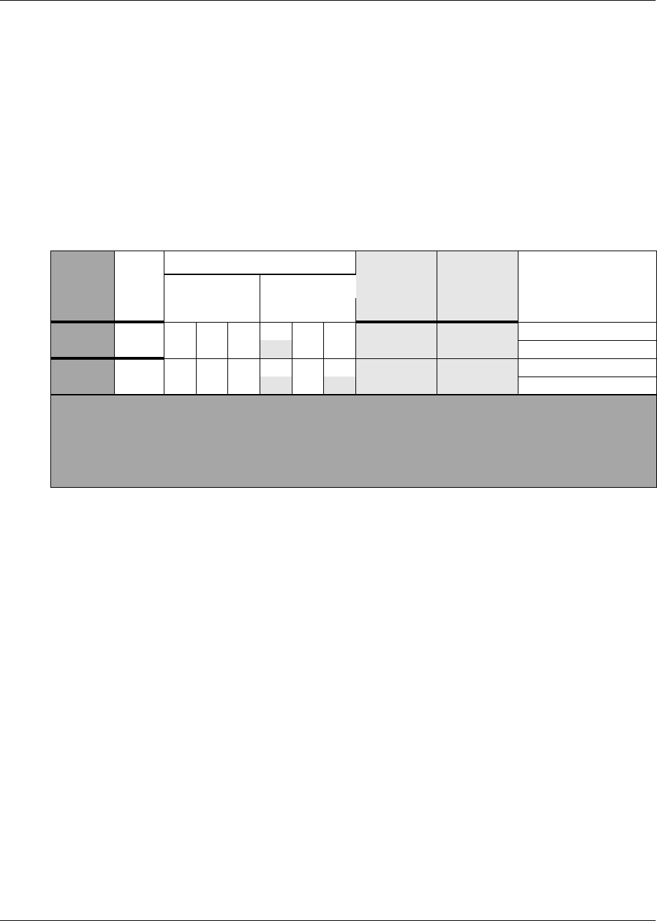
Telephony Hardware Selection and Settings 343
Installation and Maintenance Guide
DECT switch settings
The DECT module supports a maximum of eight DECT radio base station connections. This
module occupies one full DS30 bus, which can support a maximum of 32 cordless handsets when
all eight base stations are deployed. The DECT module should be installed on DS30 6 or 7.
For detailed instructions about using the DECT module, refer to the Business Communications
Manager 3.0 DECT Installation and Maintenance Guide.
Table 66 shows the settings for DS30 6 and 7, and the assigned dialing numbers (DNs).
Table 66 DECT module settings
Select
DS30
bus
Select
offset
Set the switches Use these
DNs on 3.0
system
Use these
DNs on
updated 2.0
system
**Custom DN rangeOffset DS30 channel
123456
60
on on on on on 597-624* 501-532*
off
7*** 0 on on on on 597-624* 501-532*
off off
*If you need more DNs, use DNs in the 565 to 596 range. Ensure no other devices are assigned to these
DNs before you use them. Change the DN type field to ISDN and DECT.
**The extensions listed are based on a three-digit DN with a Start DN of 221. If your system has longer DNs
or a different Start DN, enter the range in the blank column.
***If your system is configured with a 3/5 channel split, DS30 7 is not available.
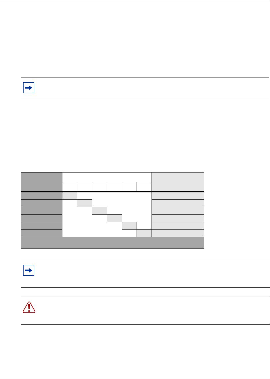
344 Telephony Hardware Selection and Settings
P0993133 03
FEM switch settings
The DIP switches on the underside of the FEM module are used to turn the six ports on the front of
the module on or off. You need to turn a port on for each Norstar expansion module you want to
connect to the Business Communications Manager. Each port also occupies one full DS30
channel. Therefore, if you have a fully-configured, six-module Norstar system to convert, you
need to turn on all six ports on the FEM, and, therefore, no other module can be installed in the
Business Communications Manager.
To turn on a fiber port, set the DIP switch for the corresponding DS30 bus, as shown in Table 67.
For example, if you want to use fiber port 2, turn on DIP switch 2 (DS30 3). After the module is
installed, an LED lights beside each active fiber port.
Table 67 shows the switch for each fiber port.
Note: The FEM module only supports connections to the Norstar trunk and station
expansion modules.
Table 67 FEM switch settings
Choose a port
to turn on
Set this switch to turn on the port This DS30 bus gets
assigned
123456
1ON 2
2ON 3
3ON 4
4ON 5
5ON 6
6ON 7***
***If your system is configured with a 3/5 channel split, DS30 7 is not available.
Note: If you turn on all six switches, you are using all the DS30 numbers. In this case, the
Business Communications Manager can support only the FEM module. All other media
bays must be empty.
Warning: Do not attempt to turn on ports requiring a DS30 bus that is already in service
to another media bay module located on the same Business Communications Manager.
Doing this results in unpredictable behavior with both modules.
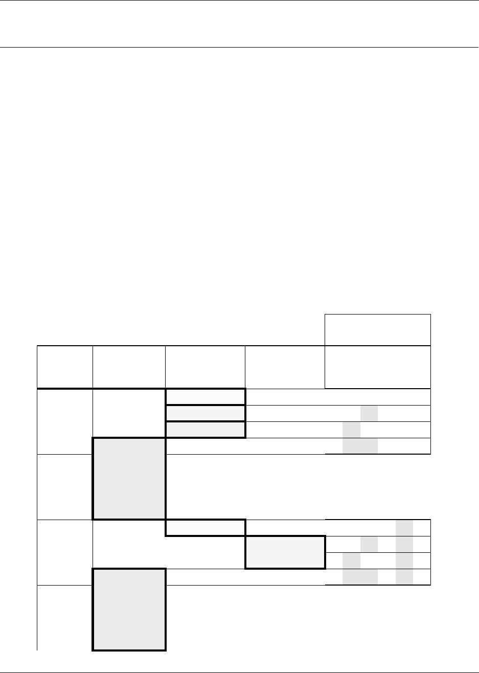
345
Installation and Maintenance Guide
Appendix C
Media Bay Module Combinations
This section describes some combinations of trunk and station modules to demonstrate how to fit
the modules into the DS30 channel resources. These configurations are meant to help demonstrate
how your system can be configured using the information in this guide and do not necessarily
reflect real-life configurations.
Combining CTMs and 4X16s
The 4X16 combination media bay module is a combination of a CTM and a DSM. A maximum of
four CTMs can fit into a DS30 channel, when each is given a different offset. Therefore, you can
combine a maximum of three CTMs with a 4X16 combination module. This configuration would
occupy two full DS30 channels.
You can install a maximum of three of the above combinations in a Business Communications
Manager system with an extension unit added to it. Table 68 demonstrates this configuration of
CTMs and 4X16 modules, including the switch settings for each module.
Table 68 CTMs combined with 4X16 modules
Each heavily-outlined and shaded square
represents one module. Switch setting
DS30
channel #
2
4x16s
Offset 3
4
CTMs
Offset 0, 1 and 2
1
CTM8
Offset 2 123456
20 CTM settings: on on on on on on
1 CTM settings: on on off on on on
2 CTM settings: on off on on on on
3 Switch settings for 4X16: on off off on on on
3
40 CTM settings: on on on on off on
2ononoff on off on
on off on on off on
3 Switch settings for 4X16: on off off on off on
5
346 Media Bay Module Combinations
P0993133 03
Fully-loaded Setup
This section describes a system containing one DSM 32/32+, one DSM 16/16+, two ASM 8s, and
two DTMs. This configuration uses all the DS30 channels, with the exception of two offsets.
Table 69 demonstrates this combination, including the switch settings for each module.
Table 69 DSM combined with 2 DTMs and 2 ASMs
DS30
channel
#
Each heavily-outlined and shaded square represents one
module. Switch setting
1
DSM 32/32+
Offset 0
1
DSM 16/16+
Offset 0
2
ASM 8s
Offset 0 and 1
2
DTMs
Offset 0 123456
20 DSM 32 settings: on on on on on on
3
40 DSM 16 settings: on on on on off on
50 ASM8 settings: ononononoff off
1 ASM8 settings: on on off on off off
60onononoff on on
70onononoff on off
Media Bay Module Combinations 347
Installation and Maintenance Guide
Table 70 demonstrates either a full double density system or a partial double density system
because DS30 06 and 07 have trunk modules installed. Double density only affects system
modules.
Table 70 All station modules set for double density
DS30
channel
#
Each heavily-outlined and shaded square represents one
module. Switch setting
1
DSM 32+
Offset 0
1
DSM 16+
Offset 0
2
ASM 8s
Offset 0 and 1
2
DTMs
Offset 0 123456
20 DSM 32+ settings: offononononon
30 DSM 32+ settings: offononononoff
40 DSM 16+ settings: offonononoff on
0 DSM 16+ settings: off on off on off on
50 ASM8 settings: ononononoff on
1 ASM8 settings: on on off on off on
0 ASM8 settings: on off on on off on
1 ASM8 settings: on off off on off on
60 onononoff on on
70 onononoff on off
348 Media Bay Module Combinations
P0993133 03
Table 71 Demonstrates a partial double density system (PDD - the default setting for 3.0), where
Companion can be installed on DS30 06 and 07.
Table 71 Two double density DSMs, plus a single-density DSM for Companion
DS30
channel
#
Each heavily-outlined and shaded square
represents one module. Switch setting
1
DSM 32+
Offset 0
2
DTMs
Offset 0 123456
20 DSM 32+ settings: offononononon
30 DSM 32+ settings: off on on on on off
40ononononoff on
50ononononoff off
60 DSM 32+ set to single
density for Companion: on on on off on off
7
Media Bay Module Combinations 349
Installation and Maintenance Guide
DECT Combinations
This section describes a system containing a DECT module, three BRI modules and two DSM 32s.
This configuration uses all the DS30 channels, with the exception of one offset.
Table 72 demonstrates this combination, including the switch settings for each module.
Note: DECT systems are not available for all profiles. Refer to “Mobility Services by
Region” on page 303.
Table 72 Three BRI modules, two DSM 32s and 1 DECT module
DS30
channel #
Each heavily-outlined and shaded square
represents one module. Switch setting
1
DECT
Offset 0
3
BRI
Offset 0, 1 and 2
2
DSM 32s
Offset 0 123456
20 onononononon
3
40 ononononoff on
5
60 DECT switch settings: on on off on on on
70 BRI settings on on on off on off
1 BRI settings on on off off on off
2BRI settingsonoff on off on off

350 Media Bay Module Combinations
P0993133 03
Changing Configurations
Here are some points to consider when changing modules in existing or in new Business
Communications Manager systems:
• Trunk and analog station modules cannot share a DS30 channel.
• Modules that require more than one DS30 channel automatically assign the next channel in
chronological order.
Therefore, if an existing, installed module uses either of the required DS30 channels, remove
the installed module. You must then assign the DIP switches for both modules so there is no
conflict between them or with any other installed module.
• The goal is to have a balanced mix of trunk and station modules.
• Write the DIP switch settings for each module in a place that is handy to reference when you
decide to change or add modules.
• If you update your Norstar system to Business Communications Manager, your station
amphenol connectors can be connected into the media bay modules without adjustment. Trunk
connectors must be converted to RJ11 (CTM) or RJ45 (BRI) connectors.
However, if you use the FEM module to connect your Norstar modules to the Business
Communications Manager, the station wiring needs to be adjusted. Refer to “FEM Wiring” on
page 124.
System Setup
Use the following table to make a note of your basic system setup. Post this page near the Business
Communications Manager hardware for future reference.
DS30 channel 2 DS30 channel 3 DS30 channel 4
Media bay module
DIP switch setting
Line/set type
Line/Loop/DN range
DS30 channel 5 DS30 channel 6 DS30 channel 7
Media bay module
DIP switch setting
Line/set type
Line/Loop/DN range

Media Bay Module Combinations 351
Installation and Maintenance Guide
Set DNs and Port Numbers
The media bay module, based on the switch settings of the module, defines which DNs and port
numbers can be populated with telephones. If you have changed the default start DN for your
system, use Table 73 to identify the DNs and ports for your sets. If you are using the default start
DN (211), a completed chart is provided in Table 25 on page 244.
Table 73 Cross referencing ports and DNs
Pin Wire color DS30
channel 2 DS30
channel 3 DS30
channel 4 DS30
channel 5 DS30
channel 6 DS30
channel 7
26 White-Blue DN
Port 201
DN
Port 301
DN
Port 401
DN
Port 501
DN
Port 601
DN
Port 701
1Blue-White
27 White-Orange DN
Port 202
DN
Port 302
DN
Port 402
DN
Port 502
DN
Port 602
DN
Port 702
2Orange-White
28 White-Green DN
Port 203
DN
Port 303
DN
Port 403
DN
Port 503
DN
Port 603
DN
Port 703
3Green-White
29 White-Brown DN
Port 204
DN
Port 304
DN
Port 404
DN
Port 504
DN
Port 604
DN
Port 704
4Brown-White
30 White-Slate DN
Port 205
DN
Port 305
DN
Port 405
DN
Port 505
DN
Port 605
DN
Port 705
5Slate-White
31 Red-Blue DN
Port 206
DN
Port 306
DN
Port 406
DN
Port 506
DN
Port 606
DN
Port 706
6Blue-Red
32 Red-Orange DN
Port 207
DN
Port 307
DN
Port 407
DN
Port 507
DN
Port 607
DN
Port 707
7Orange-Red
33 Red-Green DN
Port 208
DN
Port 308
DN
Port 408
DN
Port 508
DN
Port 608
DN
Port 708
8Green-Red
34 Red-Brown DN
Port 209
DN
Port 309
DN
Port 409
DN
Port 509
DN
Port 609
DN
Port 709
9Brown-Red
35 Red-Slate DN
Port 210
DN
Port 310
DN
Port 410
DN
Port 510
DN
Port 610
DN
Port 710
10 Slate-Red
36 Black-Blue DN
Port 211
DN
Port 311
DN
Port 411
DN
Port 511
DN
Port 611
DN
Port 711
11 Blue-Black
37 Black-Orange DN
Port 212
DN
Port 312
DN
Port 412
DN
Port 512
DN
Port 612
DN
Port 712
12 Orange-Black
38 Black-Green DN
Port 213
DN
Port 313
DN
Port 413
DN
Port 513
DN
Port 613
DN
Port 713
13 Green-Black
39 Black-Brown DN
Port 214
DN
Port 314
DN
Port 414
DN
Port 514
DN
Port 614
DN
Port 714
14 Brown-Black
40 Black-Slate DN
Port 215
DN
Port 315
DN
Port 415
DN
Port 515
DN
Port 615
DN
Port 715
15 Slate-Black
41 Yellow-Blue DN
Port 216
DN
Port 316
DN
Port 416
DN
Port 516
DN
Port 616
DN
Port 716
16 Blue-Yellow

352 Media Bay Module Combinations
P0993133 03

353
Installation and Maintenance Guide
Appendix D
System Options
The Business Communications Manager system provides a number of software applications that
enhance basic functionality.
Some of the telephony applications work immediately after you install the Business
Communications Manager system, this is considered core software. Other applications are enabled
when you enter software keycodes, which you generate when you purchase one of the
applications.
Refer to the Business Communications Manager Software Keycode Installation Guide for specific
directions for entering a code.
Telephony Features and Options
The telephony features and options have individual installation and features guides. This section
lists the application guides and provides a brief description of the application function.
•Programming Operations Guide and Telephone Features Programming Guide
These guides provide programming for core telephony features and user features, such as:
— Voice telephony configuration for digital, IP, ISDN and radio-based telephones and
equipment over analog, digital, ISDN, and voice over IP (VoIP) trunks.
— How to use and program user telephony features at the telephone
— Companion Application Server software that controls the interface between the Business
Communications Manager system and the Companion wireless system (available for
selected regions)
— Networking DPNSS (upgrade) (requires keycode) provides private voice networking for
the UK Market.
— Networking MCDN and EDSI Q.SIG Voice Networking (requires keycode) allows you to
network your Business Communications Manager system, or a number of Business
Communications Manager systems to a Meridian system. This allows the network to use a
common numbering plan, as well as common voice messaging and auto attendant systems
connected to the Meridian.
— Data setup applications and protocols to configure the Business Communications Manager
system to be part of a LAN or WAN network. Refer to the next section for specifics.
•Attendant Console Setup and Operation Guide and Attendant Console User Guide
Attendant Console (requires keycode) provides centralized call management and call activity
reporting to a business. The three components of this application create a system that
communicates with the Business Communications Manager, provides call management
options, and reports how incoming calls are handled within a business.
•Call Center Agent User Guide and Call Center Supervisor User Guide

354 System Options
P0993133 03
Nortel Networks Call Center Agents (requires keycode) allows the addition of a specific
number of call center agents to your system. Comes in versions for one, four, eight, 16, 32 and
64-seat authorization codes.
• Call Center Set Up and Operation Guide
— Nortel Networks Call Center (requires keycode)— this Automatic Call Distribution
(ACD) system provides tools for handling incoming calls to an agent network. The
application also provides administration, supervision, and reporting tools.
— Nortel Networks Professional Call Center (upgrade) (requires keycode)— this is an
expanded version of the basic Call Center application.
• Call Center Reporting Set Up and Operation Guide
Nortel Networks Call Center Reporting (requires keycode) monitors the statistics of a call
center. This application is also compatible with IP wallboards from Itel and SYMON.
• Call Detail Recording System Administration. Guide
Call Detail Recording (no keycode required) records and reports call activity from the Business
Communications Manager. You can create reports from this information to help you manage
system usage effectively.
• CallPilot Reference Guide
CallPilot is a core Business Communications Manager application. It works with the telephone
system to provide automated receptionist service by answering incoming calls and routing
them to telephones or mailboxes on the system. This guide explains what the various parts of
the CallPilot application do.
•CallPilot Manager Set Up and Operation Guide and CallPilot Programming Record
— CallPilot Manager is the web-based application that you use to set up and administer
CallPilot.
— Automated Attendant is the CallPilot answering service that answers incoming calls with a
Company Greeting, plays a list of options to a caller, and performs call routing functions
in response to caller selections.
— CallPilot (requires keycodes for additional voice mailboxes) provides a voice mail
application as part of the core Business Communications Manager programming.
CallPilot provides voice messaging, Automated Attendant, and Custom Call Routing
features for Business Communications Manager telephony services.
— Voice Mailbox Expansion (requires keycode) allows you to add extra mailboxes to your
voice messaging system. The application comes with a keycode that defines how many
extra mailboxes are allowed.
•CallPilot Fax Set up & Operation Guide and CallPilot Fax User Guide
Fax Suite (requires keycode), a CallPilot optional feature, delivers fax messages to CallPilot
mailboxes. Users can use the application to send and retrieve fax messages as easily as they
send and retrieve voice messages.
•CallPilot Message Networking Setup and Operation Guide and CallPilot Message Networking
User Guide

System Options 355
Installation and Maintenance Guide
Message Networking (requires keycode to add extra mailboxes) links the CallPilot system
with other voicemail systems and allows the exchange of voice messages between users at
different sites. CallPilot supports Digital networking using Voice Profile for Internet
Messaging (VPIM) standard, and Audio Messaging Interchange Specification (AMIS)
networking.
• CallPilot Desktop Messaging Software Install and Maintenance Guide
Desktop Message Networking (requires keycode) provides a multimedia messaging
application that works with an e-mail client to provide a single graphical user interface
CallPilot voice, fax, and text messages, as well as e-mail messages.
• DECT Installation and Maintenance Guide (region-specific)
The DECT radio-based system allows you to configure up to 32 cordless handsets that
communicate through radio base stations deployed around a site. The handsets can be
configured as stand-alone sets, or they can be twinned with stationary sets.
• IP Telephony Configuration Guide
— i2002 and i2004 IP telephones and the NetVision and NetVision Data telephones require a
combination of data and telephony settings to work with the Business Communications
Manager. These telephones can make or receive calls through either VoIP or PBX lines.
— Nortel Networks i2050 Software Phone turns your PC into a telephone interface which
provides standard telephony operating features such as Voice Mail, Caller ID, and
multiple telephone lines or line appearances. This application requires Windows 2000, a
full duplex sound card, and a computer-telephony headset. This document describes what
settings are required to use this application with the Business Communications Manager.
The i2050 Software Phone Installation Guide provides specific installation information.
— VoIP Gateway (requires keycode) converts the voice in a call into a packet format and
sends the call using an intranet trunk. With Business Communications Manager VoIP
Gateway, you can make calls over any intranet connected to the Business
Communications Manager system.
• LAN CTE Configuration Guide
— LAN CTE (introduced in 2.5 to replace TSP) (requires keycode) provides an interface
between a Personal Computer (PC), a telephone, and the Business Communications
Manager server that allows third-party software to function on personal computers on the
same network as the Business communication manager. This allows customized solutions
for such applications as hotel/motel packages or text messaging programs.
— TSP (version 2.0 systems only) (requires keycode) supplies the interface between the
Business Communications Manager system and Microsoft TAPI. This interface allows
you to use TAPI applications on the Business Communications Manager system.
•Multimedia Call Center Setup and Operation Guide and Multimedia Call Center Web
Developers Guide
Nortel Networks Multimedia Call Center (requires keycode) allows call agents and users to
interact through either or both a telephone connection and an IP connection. This allows the
conversation to occur over the voice connection or through text chatting. Further, this
application allows exchange and viewing of web pages, and allows the agent to show the client
screen captures.

356 System Options
P0993133 03
• Personal Call Manager User Guide
Personal Call Manager, a TAPI-based application, provides a graphical interface that allows
you to use your computer to manage your calls and address book, while still using your
telephone for voice communication.
• Interactive Voice Response Installation and Configuration Guide
Interactive Voice Response is an automated telephony application that prompts callers with a
combination of recorded menus and prompts, and real-time data from databases. Users enter
digits from their touch-tone key pad that directs the Interactive Voice Response application to
access databases and play information back to the caller.
Interactive Voice Response documents include the following:
•Media Processing Server Series COMMGR Reference Manual P0988083
•PeriView Reference Manual P0988083
•PeriReporter User’s Guide P0988093
•BCM-IVR Integration Supplement P0995957
Data Features
The Business Communications Manager offers the following data features as described and
configured in the Business Communications Manager 3.0 Programming Operations Guide:
• Integrated QoS Routing controls the router interface between the Business Communications
Manager system and the local area network, wide area network, and internet.
•DHCP (Dynamic Host Configuration Protocol) — Business Communications Manager 2.5
provides DHCP service to branch office clients. This service dynamically assigns IP addresses
to branch office PCs, so you do not manually assign an IP address to each PC. The Business
Communications Manager can also be set to use this application as a relay agent to an external
DHCP server on the network.
•DNS (Domain Name System) — Business Communications Manager 2.5 functions as both a
gateway to the internet and as a DNS proxy for your network. The DNS service allows clients
to enter a domain name, such as www.nortelnetworks.com, instead of an IP address when
using web browsers.
•IP Routing — Business Communications Manager 2.5 supports the following IP routing
protocols:
— static routing
— RIP (Routing Information Protocol)
— OSPF (Open Shortest Path First)
•IPX Routing — Business Communications Manager 2.5 supports the following IPX Routing
protocols in a NetWare environment:
— static routing
— RIP (Routing Information Protocol)
— SAP (Service Advertising Protocol)

System Options 357
Installation and Maintenance Guide
•NAT (Network Address Translation) — Business Communications Manager 2.5 supports
both static and dynamic NAT for a number of packet types and protocols. NAT is a network
security feature that translates the IP addresses used within your private network to different IP
addresses known to internet users outside your private network.
•Policy Management — Business Communications Manager 2.5 allows you to implement
classes of service and assign priority levels to different types of traffic using the DiffServ
network architecture. You can configure policies that monitor the characteristics of traffic (for
example, its source, destination, and protocol) and perform a controlling action on the traffic
when certain user-defined characteristics are matched.
•VPN (Virtual Private Networks) — Business Communications Manager 2.5 uses the PPTP
(point to point tunneling protocol) and IPSec (IP security) tunneling protocols to create secure
extranets. These secure extranets provide safe transport of data to and from the Business
Communications Manager using the public data network (PDN).

358 System Options
P0993133 03

359
Installation and Maintenance Guide
Glossary
access code
A unique digit or digits entered by the user to access some telephony features such as Line
pools, Call park, external lines, Direct-Dial telephone, and Auto DN.
address
A unique identifier assigned to networks and stations that allows each device to receive
and reply to messages.
Analog terminal adapter (ATA)
A device that connects analog telecommunication devices, such as fax machines,
answering machines, and single line telephones to the Business Communications Manager
system through a Digital station module.
Application program interface (API)
An application program uses this interface to make requests of the operating system or
another application. The API is an interface to an operating system or a program.
asynchronous
A method of transmission where the time intervals between characters are not required to
be equal and signals are sourced from independent clocks with different frequencies and
phase relationships. Start and stop bits may be added to coordinate character transfer.
autodial button
A memory button that provides one-touch dialing out.
automatic daylight savings time
A feature that switches the system to standard or daylight savings time at programmed
times. Assigns automatic daylight savings time under Daylight time in System
programming.
automatic telephone relocation
A feature that maintains personal and system programing for a telephone keep when the
telephone gets moved to a different modular jack. Enable Automatic Telephone
Relocation under Set relocation in System programming.
auxiliary ringer
An external telephone ringer or bell which rings when a line or a telephone rings. Enables
the auxiliary ringer under Capabilities under System DNs programming. Program an
auxiliary ringer in Services programming.
B channel (bearer channel):
An ISDN standard transmission channel used for voice or data transmission. Also known
as a media channel.

360 Glossary
P0993133 03
background music
A feature that plays music from the speaker of your telephone. Background Music is
available when you attach a music source to the system and enable the feature under
Feature settings in System programming.
base station
This is the radio/telephony unit that allows communication between wireless handsets,
such as Companion or DECT, to the Business Communications Manager system.
basic rate interface (BRI)
An ISDN interface that uses two B channels and a D channel (2B+D). ETSI BRI is the
European Telecommunications Standards Institute specification for BRI ISDN service
baud rate
A unit of measurement of data transmission speed. Baud rate is approximately equivalent
to Bits Per Second (BPS). Typical baud rates are 300, 1200, 2400, 4800, and 9600.
BIOS (basic input output system)
A program contained in Read Only Memory (ROM) that acts as the interface between
software programs and the computer hardware.
bit
A bit is the smallest unit of information identified by the computer. A bit has one of two
values, 0 or 1, to indicate off or on.
Bus
A collection of communication lines that carry electronic signals between components in
the system.
Call Forward
A feature that forwards all the calls arriving at a telephone to another telephone in the
system. To have calls forwarded outside the system, use Line Redirection.
Call Forward No Answer
A feature that forwards all calls arriving at a telephone to another selected telephone in the
system. The system transfers the calls after a specific number of rings. Assign Call
Forward No Answer under Capabilities in System DNs programming.
Call Forward On Busy
A feature that forwards all calls at a telephone to another selected telephone if the original
telephone is busy. Assign this feature under Capabilities in System DNs programming.
Call Forward Override
An automatic system feature that allows the user to call another user and ask that user to
stop forwarding calls to their set.

Glossary 361
Installation and Maintenance Guide
call log
An incoming call log accessed through the set that displays the following information for
every call:
• sequence number within the Call Log
• name and number of caller
• long distance indication
• call answered indication
• time and date of the call
• number of repeated calls from the same source
• name of the line that received the call
Camp-on
A feature that allows the user to reroute a call to a telephone when all the lines on that
telephone are busy. To answer a camped call, use Call Queuing or select a line if the
camped call appears on the set. Queued calls get priority over camped calls.
camp timeout
The length of a delay before a camped call returns to the telephone that camped the call.
Set the length of delay under Feature settings in System programming.
central answering position (CAP)
An M7324 telephone that provides backup answering and set monitoring. Assign a CAP
under CAP assignment in System programming.
channel service unit (CSU)
A device on the Digital Trunk Interface that is the termination point of the T1 lines from
the T1 service provider. The CSU collects statistics on the quality of the T1 signal. The
CSU ensures network compliance with FCC rules and protects the network from harmful
signals or voltages.
client
A client is a computer system or process that requests a service of another computer
system or process. For example, a workstation requesting the contents of a file from a file
server is a client of the file server.
cold start
A cold start occurs when you lose all system programming, or if the system was down for
maintenance and you want to start it up again.
Companion portable telephone
Hand held wireless telephones that allow complete mobility within the reach of
Companion base stations or an external antenna. Portable telephones provide many but not
all standard system features. They also share some of the same programming as desk
telephones.

362 Glossary
P0993133 03
Companion Wireless
The name for the communication systems which use radio technology to transmit and
receive signals between its components and the Business Communications Manager.
Conference
A feature that allows the user to establish a three-way call.
D channel (Data channel)
An ISDN standard transmission channel which is packet-switched. The channel is used for
call setup, signaling, and data transmission.
data link connection indentifier (DLCI)
The DLCI is used to identify a PVC in frame relay networks.
DECT cordless telephone system
Hand held wireless telephones that allow complete mobility within the reach of DECT
base stations. Portable telephones provide many but not all standard system features. They
also share some of the same programming as desk telephones.
Delayed Ring Transfer (DRT) to prime
This feature allows the system to transfer unanswered calls on external line to the prime
telephone related to the called set. The number of rings can be adjusted. Activate this
feature under Feature settings in System programming.
dial-up connection
A dial-up connection is a temporary connection between computers. This connection is
established over an analog or digital telephone line.
dialing restriction
Restrictions are numbers you cannot dial when the dialing filter with those numbers is in
effect.
Digital Private Network Signaling System (DPNSS)
DPNSS is a networking protocol that provides operators with access to Enterprise Edge
features over multiple combined networks. Corporate offices, separated geographically,
can be linked over DPNSS to other Enterprise Edge systems, bypassing the restrictions of
the PSTNs to which they may be connected. This allows connected Enterprise Edge
systems to function like a private network. DPNSS is available for International systems
only.
directory number (DN)
A unique number that the Business Communications Manager system assigns to every
telephone or data terminal.

Glossary 363
Installation and Maintenance Guide
disconnect supervision
A feature that enables the system to detect if an external caller hangs up. Enable
Disconnect Supervision under Trunk/Line data in Lines programming.
Do Not Disturb
A feature that stops calls from ringing at a telephone. Only Priority Calls ring at the
telephone when this feature is set. A line button flashes when a call is received, but the set
does not ring.
domain name
The domain name is used to translate Internet IP addresses into common language to allow
for easier user access.
Domain Name Server (DNS)
The domain name system or server is the system that maps names of objects into IP
numbers or other resource record values.
dual tone multifrequency (DTMF)
Two distinct telephone signaling tones used for dialing.
dynamic IP address
This feature is provided by an IP address server which assigns an IP address to a computer
every time it logs on to the network.
Emergency 911 dialing
The ability to access a public emergency response system by dialing the digits
9-1-1.
emergency telephone
A single-line telephone that becomes active when there is no power to the Business
Communications Manager. This telephone is also referred to as a 500/2500 telephone.
Ethernet
A local area network that networks computers with coaxial cable or twisted pair wiring.
This protocol makes use of Carrier Sense Multiple Access/Collision Detect (CSMA/CD)
LAN to allow computers, such as the Business Communications Manager to listen for
pauses before they communicate.
event message
These are messages generated by the system to record activity. The messages are written
to the system log.
external call
A call to or from a destination outside the Business Communications Manager system.

364 Glossary
P0993133 03
external line
A line assigned to a telephone that allows calls to the PSTN.
external paging
A feature that allows voice announcements over an externally-installed loudspeaker
connected to the Business Communications Manager. The external speaker is not an
Business Communications Manager component.
FAX
FAX works with Business Communications Manager Voice Messaging. FAX allows a
caller to send a fax document to a voice mailbox.
feature code
A unique code used to access Business Communications Manager features and options on
the telephones.
filtering
Filtering is the process of examining a data packet on the network to determine the
destination of the data and whether the packet gets passed along on the local LAN, copied
to another LAN, or dropped.
frame relay
A frame relay is a high-speed, packet switching WAN protocol designed to provide
efficient, high-speed frame or packet transmission with minimum delay. Frame relay uses
minimal error detection and relies on higher level protocols for error control.
gateway
A system that links two different types of networks and enables them to communicate with
each other. The Business Communications Manager can provide the gateway to an
intranet or internet.
ground start trunk
Ground start trunks provide the same features as loop start trunks. Use this type of trunk
when the local service provider does not support disconnect supervision for the digital
loop start trunks. By configuring lines as ground start, the system can identify when a
caller hangs up the telephone at the far end. Ground start trunks are available only on a
Digital Trunk Interface (DTI).
Handsfree
A feature used to make calls without using the telephone receiver. Activate Full Handsfree
under Capabilities in System DNs programming. When activated, the Business
Communications Manager assigns a Handsfree/Mute button to the telephone.

Glossary 365
Installation and Maintenance Guide
Handsfree (HF) Answerback
This feature automatically turns on the microphone at a telephone that receives a Voice
Call so that the person receiving the call can respond without lifting the receiver. Activate
Handsfree Answerback under Capabilities in System DNs programming.
Held (Line) Reminder
A telephone rings and displays the message On hold: LINENAM when you place an
external call on hold for programmed period of time.
host name
The name that identifies a computer, on a network that provides services to other
computers in the domain, such as databases or other Business Communications Manager
systems.
Hotline
This feature automatically calls a pre-assigned number when the user lifts the telephone
receiver or presses the Handsfree/Mute button. Assign Hotline under Capabilities in
System DNs programming.
Hypertext Transfer Protocol (HTTP)
The set of rules used for exchanging text, graphic images, sound, video, and other
multimedia files on the world wide web.
Hz (hertz)
A unit of measure for indicating frequency in cycles per second.
Integrated Services Digital Network (ISDN)
A digital telephone service that allows for a combination voice and data transfer over a
single, high-speed connection over the same copper twisted-pair telephone line as analog
telephone service.
intercom button
A button that provides access to internal lines used for calls within a Business
Communications Manager system. These buttons also provide access to external lines
through a line pool or external code. Assign intercom buttons under Line access in
System DNs programming.
internal line
A line on your telephone dedicated to making calls to destinations inside your system. An
internal line can connect you with an external caller if you use it to access a line pool.
Also, you can answer an external caller using the call handling features such as Call Park
or Call Pickup Directed.

366 Glossary
P0993133 03
Internet Protocol (IP)
The protocol that supports data being sent from one computer to another through an
interconnection (internet) of networks. IP is a connectionless protocol, which means that
there is no established connection between the end points that are communicating.
IP address
The internally-assigned address that identifies a destination and transmitting computer
over a internet. See also static IP address and dynamic IP address.
IP address server
The IP address server manages the assignment of IP addresses to the devices that access
the system. The server assigns an IP address to the device whenever it logs on to the
network.
ISDN DN
A directory number (DN) used by ISDN terminal equipment connected to the system. The
Business Communications Manager system uses a maximum of 30 ISDN DNs. The
DECT cordless handsets use this type of DN.
kbyte
The abbreviation for kilobyte. A kilobyte is equal to 1024 bytes.
keycode
These numerical codes, generated for specific applications and for individual sites, allow
access to additional features on the Business Communications Manager system. Refer to
the Software Keycode Installation guide for details.
line
The complete path of a voice or data connection between one telephone, or other device,
and another.
line number
A number that identifies an external line. The total number of lines depends on the number
and type of trunk media bay modules installed.
line pool
Lines grouped in a common pool that assigned telephones can access to make external
calls. Assign a line to be part of a line pool under Trunk/Line data in Lines programming.
Line Redirection
A feature that allows you to redirect all calls on an incoming line to a destination outside
the system. You can set up the system to ring briefly when a call comes in on a redirected
line, under Capabilities in System DNs programming.
This feature is different from Call Forward in two ways. Line redirection redirects only
external calls, and redirects calls to destinations outside the system. Call forward redirects
calls only to destinations within the system.

Glossary 367
Installation and Maintenance Guide
Link
If the Business Communications Manager system is connected to a Private Branch
Exchange (PBX), the Link signal is used to access special features. The Link signal can be
included as part of a longer stored sequence on an External Autodial button or in a Speed
Dial code. The Link symbol uses two of the 24 spaces in a dialing sequence.
Local Area Network (LAN)
A network of interconnected computers, such as the Business Communications Manager,
sharing the resources of a single processor or server within a relatively small geographic
area.
mailbox
A storage place for voice messages on Business Communications Manager Voice
Messaging.
Meridian 1 ISDN Primary Rate Interface
This is the MCDN protocol which is used between members of the Nortel Networks
Meridian family of Private Telecommunication Network Exchanges. The signalling
information is carried via time slot 16 of a 2.048 Mbit/s digital transmission system.
MHz
A unit of measure indicating frequency in millions of cycles per second.
microprocessor
The Central Processing Unit (CPU) component that controls all activity inside the
Business Communications Manager.
modem
A communications device that allows computers to exchange data over telephone lines.
music source
You can connect a radio or other source of music to the system to provide music for the
Music on Hold and Background Music features. A music source is not part of the Business
Communications Manager system components.
Network Basic Input/Output System (NetBIOS)
An interface and upper-level protocol developed by IBM for use with a proprietary
adapter for its PC network product. NetBIOS provides a standard interface to the lower
networking layers. The protocol provides higher-level programs with access to the
network.
network
Two or more computers linked electronically to share programs and exchange data.

368 Glossary
P0993133 03
network device
A network device is a hardware entity characterized by its use as a communications
component within a network.
network DN
A number supplied by the ISDN network service provider for ISDN terminal equipment.
network interface card (NIC)
This card is installed inside a computer so the computer can be physically connected to a
network device such as the Business Communications Manager server.
On hold
A setting that controls what external callers hear: music, tones, or silence, when you place
the call on hold. Program On hold under Feature settings in System programming.
overflow
A setting in Routing Service that allows users to decide which path an outgoing call takes
if all the lines used in a selected route are in use.
packet
A packet is a unit of data that is routed between an origin and a destination. Each packet is
separately numbered and includes the Internet address of the destination.
Packet and datagram are similar in meaning. A protocol similar to TCP, the User
Datagram Protocol (UDP) uses the term datagram.
page
A feature you can use to make announcements over the Business Communications
Manager system using the telephone speakers and/or external speakers.
Page Time out
A setting that controls how long a Page Announcement can last. Assign the Page Time out
under Feature settings in System programming.
Page zone
An area in the office that receives internal page announcements that other areas of the
office do not hear. Assign telephones to page zones under Capabilities in System DNs
programming.
Parallel port
A port that transfers data through multiple wires. Parallel ports normally use a 25-pin
interface that transmits and receives data using a separate data line for every bit.
Peripheral Component Interconnect (PCI) Slot
Socket on the Business Communications Manager main printed-circuit board that
connects to the Business Communications Manager cards.

Glossary 369
Installation and Maintenance Guide
Personal Speed Dial
Two-digit codes (71-94) that can be programmed on the set to dial external telephone
numbers. You can access Personal Speed dial numbers only at the telephone on which
they are programmed.
Pin-1
An indicator on the first pin on an electronic component. You use this indicator to help
you correctly align the component when attaching or installing it.
Port
A connector on the Business Communications Manager that allows data exchange with
other devices, such as a printer or mouse.
portable telephone
Typically a handset containing keypad, receiver and transmitter that communications
using a radio link to a base station connected to the Business Communications Manager.
Examples: Companion, DECT.
Primary Rate Interface (PRI)
An ISDN interface that uses 23 B channels and a D channel (23B+D).
Prime line
The line the system selects for your telephone when you lift the receiver, press the
Handsfree/Mute button, or use an external dialing feature. Assign a Prime Line to a
telephone under Line access in System DNs programming.
Priority Call
If you get a busy signal when you call a person in your office, you can interrupt that
person for an urgent call. Enable this feature for a telephone under Capabilities in System
DNs programming.
Private branch exchange (PBX)
A PBX is a telephone system within an enterprise that switches calls between enterprise
users on local lines while allowing all users to share a certain number of external
telephone lines. The main purpose of a PBX is to save the cost of requiring a line for each
user to the telephone company central office since the PBX is owned and operated by the
enterprise rather than the telephone company.
protocol
A set of rules and procedures for exchanging data between computers or Business
Communications Managers on a network or through the Internet.
Proxy
A server that acts on behalf of another.

370 Glossary
P0993133 03
pulse/tone dialing
Pulse is the traditional method of dialing used by rotary-dial or push-button single-line
telephones. Tone dialing allows telephones to communicate with other devices such as
answering machines. You require tone dialing to access the features that PBX systems can
provide or to use another system remotely.
Quality of Service (QoS)
On the Internet and in other networks, QoS refers to guaranteed throughput level. QoS
allows a server to measure, improve and, to some level, guarantee the transmission rates,
error rates, and other data transmission characteristics. QoS is critical for the continuous
and real-time transmission of video and multimedia information.
Q reference point signalling (QSIG)
QSIG is an ETSI standard signalling for multi-vendor peer-to-peer communications
between PBXs and/or central offices. This is an International standard and not available in
North America.
Random Access Memory (RAM)
Computer memory that stores data temporarily. RAM stores the data used by the
microprocessor because it executes instructions. The contents of RAM are erased when
you restart or turn off the Business Communications Manager.
RAID
Redundant array of independent disks. A disk subsystem used to increase
performance and/or provide fault tolerance. RAID is a set of two or more ordinary
hard disks and a specialized disk controller that contains the RAID functionality.
Remote access
The ability to dial into an Business Communications Manager system from outside the
system and use selected features. The Class of Service determines which lines, features,
and dialing capabilities are available.
Restriction filter
Restriction filters prevent selected telephone numbers or feature codes from being dialed.
Restriction filters can be applied to lines, sets, specific lines on a set, and to Class of
Service passwords.
Read Only Memory (ROM)
Memory that stores data permanently. ROM contains instructions that the Business
Communications Manager needs to operate. The instructions stored in ROM are used by
the Business Communications Manager each time it is turned on or restarted.
Router
A device that forwards traffic between networks, based on network layer information and
routing tables. A router decides which path network traffic follows using routing protocols
to gain information about the network and algorithms to choose the best route based on a
routing matrix.

Glossary 371
Installation and Maintenance Guide
Routing
The path a message takes from its origin to its destination on a network or the Internet.
Serial port
A port that sends and receives data one bit at a time.
Software keycode
Refer to Keycode.
static IP address
A static or fixed IP address that is permanently assigned to a computer.
Station Auxiliary Power Supply (SAPS)
A device which provides power to a telephone that is more than 300 m (975 ft.) and less
than 1200 m (3900 ft.) from the server, or to a CAP module.
Station media bay module
Physical units installed in a Business Communications Manager that connect the
telephone lines to the system.
subnet mask
A value used to route packets on TCP/IP networks. When the IP layer has to deliver a
packet through an interface, it uses the destination address contained in the packet,
together with the subnet mask of the interface to select an interface, and the next hop in
that subnet
Synchronous
A synchronous signal is sourced from the same timing reference. A synchronous signal
causes the interval between successive bits, characters, or events to remain constant or
locked in to a specific clock frequency.
System speed dial code
A two-digit code (01 to 70) that you program to dial a telephone number a maximum of 24
digits long. You can program System speed dial codes for the complete system under the
System Speed heading.
SSD
The SSD (system status display) is a LED interface used to visually monitor the status of
system components.
SSM
The SSM (system status monitor) is a graphical user interface used to monitor, on-line, the
status of Business Communications Manager system components.
T1
Digital carrier system or line that carries data at 1.544 Mb/s.

372 Glossary
P0993133 03
Target lines
Lines used only to answer incoming calls. A target line routes a call according to digits it
receives from an incoming trunk. You refer to target lines in the same way as physical
lines.
Telephony Application Program Interface (TAPI)
A standard program interface that allows communication over telephones or video phones
to people or phone-connected resources elsewhere in the world.
Transfer
A feature that allows you to redirect a call to another telephone in your Business
Communications Manager system, over a network, or outside your system.
Transmission Control Protocol/Internet Protocol (TCP/IP)
A language controlling communication between computers on the Internet.
TCP:
• checks packets of information for errors
• sends requests for re-transmission in the event of errors
• returns multiple packets of a message into the original sequence when the
message reaches its destination
IP:
• controls how packets are sent out over networks
• has a packet addressing method that allows any computer on the Internet forward
a packet to another computer that is a step or more nearer to the recipient
Trunk
The public telephone system or private network connection between the Business
Communications Manager system and the outside world.
Trunk media bay module
Physical units installed in a Business Communications Manager that connect the system to
the outside world.
User Speed Dial
Two-digit codes (71-94) programmed to dial external telephone numbers. These numbers
are available only at the telephone on which they are programmed.
V.90
A data transmission standard used by the modem installed in the Business
Communications Manager. This standard allows data to be transmitted to the modem at 56
kbit/s and transmitted from the modem at 33 kbit/s.

Glossary 373
Installation and Maintenance Guide
Voice Message Center
If you have subscribed to Call Display services, you can receive visual Voice Message
Waiting Indication on a display telephone. If you have Voice Message Waiting Indication,
you can program the telephone numbers required to access a maximum of five external
voice message centers. You can program which of the five centers is to be accessed by
each specific line.
Voice over IP (VoIP)
The capability to deliver voice using the Internet Protocol. In general, this means sending
voice information in digital form in discrete packets rather than in the traditional
circuit-committed protocols of the public switched telephone network (PSTN).
Weighted Fair Queuing (WFQ)
WFQ is a queuing method that allows low volume traffic, such as Telnet, to be given
priority. Interactive traffic receives higher priority than batch transfers.
Wide Area Network (WAN)
A collection of computers or Business Communications Managers connected or
networked to each other over long distances, normally using common carrier facilities.

374 Glossary
P0993133 03
