Avaya Bcm450 Rls 6 0 Users Manual
2015-06-01
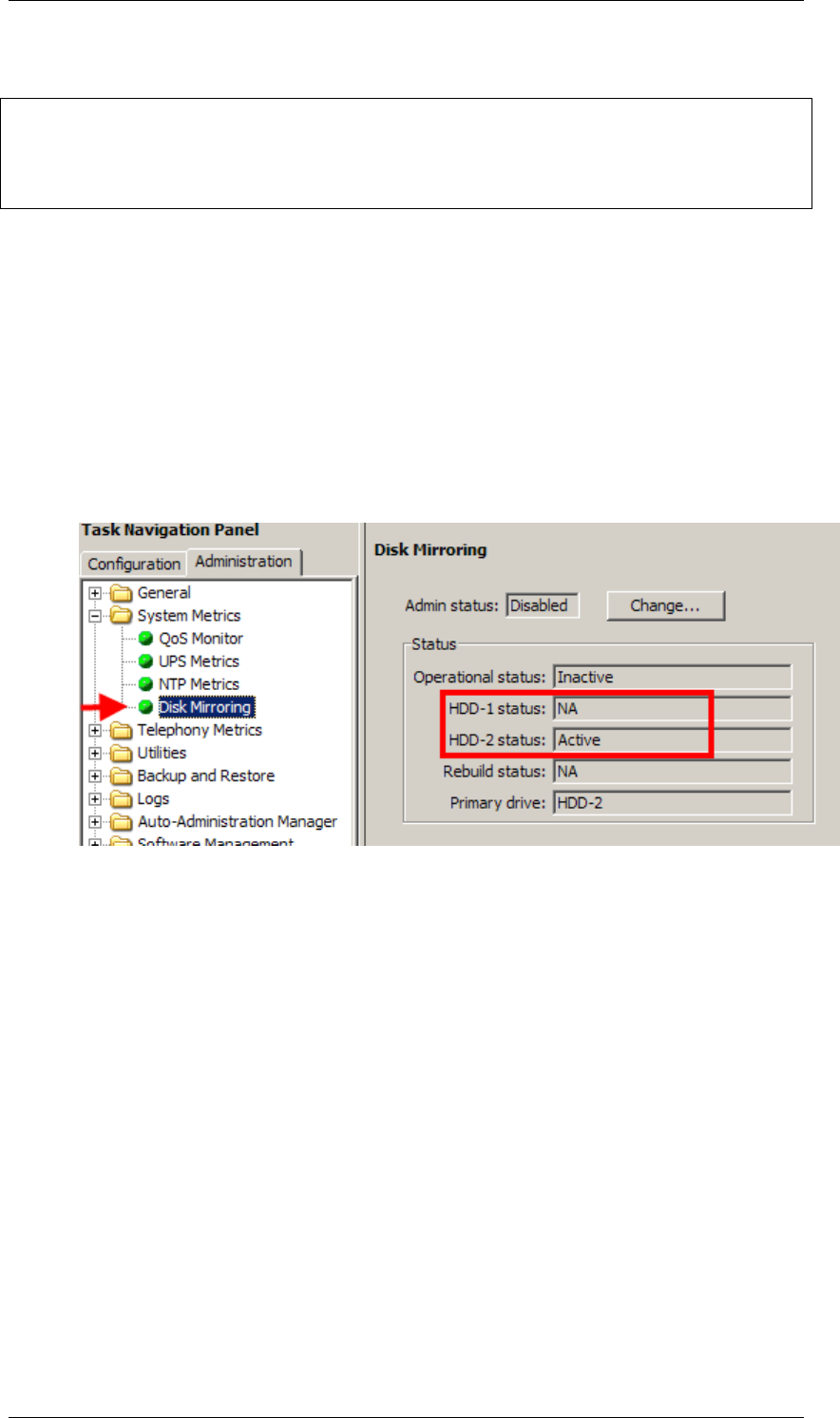
: Avaya Avaya-Bcm450-Rls-6-0-Users-Manual-736119 avaya-bcm450-rls-6-0-users-manual-736119 avaya pdf
Open the PDF directly: View PDF ![]() .
.
Page Count: 100

BCM450 Rls 6.0
Hardware & Installation
Task Based Guide

BCM450 Hardware & Installation
2 NN40011-001 Issue 1.2 BCM450 Rls 6.0
Copyright © 2010 Avaya Inc.
All Rights Reserved.
Notices
While reasonable efforts have been made to ensure that the information in this document is complete and accurate
at the time of printing, Avaya assumes no liability for any errors. Avaya reserves the right to make changes and
corrections to the information in this document without the obligation to notify any person or organization of such
changes.
Documentation disclaimer
Avaya shall not be responsible for any modifications, additions, or deletions to the original published version of
this documentation unless such modifications, additions, or deletions were performed by Avaya. End User agree to
indemnify and hold harmless Avaya, Avaya’s agents, servants and employees against all claims, lawsuits, demands
and judgments arising out of, or in connection with, subsequent modifications, additions or deletions to this
documentation, to the extent made by End User.
Link disclaimer
Avaya is not responsible for the contents or reliability of any linked Web sites referenced within this site or
documentation(s) provided by Avaya. Avaya is not responsible for the accuracy of any information, statement or
content provided on these sites and does not necessarily endorse the products, services, or information described or
offered within them. Avaya does not guarantee that these links will work all the time and has no control over the
availability of the linked pages.
Warranty
Avaya provides a limited warranty on this product. Refer to your sales agreement to establish the terms of the
limited warranty. In addition, Avaya’s standard warranty language, as well as information regarding support for
this product, while under warranty, is available to Avaya customers and other parties through the Avaya Support
Web site: http://www.avaya.com/support
Please note that if you acquired the product from an authorized reseller, the warranty is provided to you by said
reseller and not by Avaya.
Licenses
THE SOFTWARE LICENSE TERMS AVAILABLE ON THE AVAYA WEBSITE,
HTTP://SUPPORT.AVAYA.COM/LICENSEINFO/ ARE APPLICABLE TO ANYONE WHO DOWNLOADS,
USES AND/OR INSTALLS AVAYA SOFTWARE, PURCHASED FROM AVAYA INC., ANY AVAYA
AFFILIATE, OR AN AUTHORIZED AVAYA RESELLER (AS APPLICABLE) UNDER A COMMERCIAL
AGREEMENT WITH AVAYA OR AN AUTHORIZED AVAYA RESELLER. UNLESS OTHERWISE
AGREED TO BY AVAYA IN WRITING, AVAYA DOES NOT EXTEND THIS LICENSE IF THE
SOFTWARE WAS OBTAINED FROM ANYONE OTHER THAN AVAYA, AN AVAYA AFFILIATE OR AN
AVAYA AUTHORIZED RESELLER, AND AVAYA RESERVES THE RIGHT TO TAKE LEGAL ACTION
AGAINST YOU AND ANYONE ELSE USING OR SELLING THE SOFTWARE WITHOUT A LICENSE. BY
INSTALLING, DOWNLOADING OR USING THE SOFTWARE, OR AUTHORIZING OTHERS TO DO SO,
YOU, ON BEHALF OF YOURSELF AND THE ENTITY FOR WHOM YOU ARE INSTALLING,
DOWNLOADING OR USING THE SOFTWARE (HEREINAFTER REFERRED TO INTERCHANGEABLY
AS "YOU" AND "END USER"), AGREE TO THESE TERMS AND CONDITIONS AND CREATE A
BINDING CONTRACT BETWEEN YOU AND AVAYA INC. OR THE APPLICABLE AVAYA AFFILIATE
("AVAYA").
Copyright
Except where expressly stated otherwise, no use should be made of the Documentation(s) and Product(s) provided
by Avaya. All content in this documentation(s) and the product(s) provided by Avaya including the selection,
arrangement and design of the content is owned either by Avaya or its licensors and is protected by copyright and
other intellectual property laws including the sui generis rights relating to the protection of databases. You may not
modify, copy, reproduce, republish, upload, post, transmit or distribute in any way any content, in whole or in part,
including any code and software. Unauthorized reproduction, transmission, dissemination, storage, and or use
without the express written consent of Avaya can be a criminal, as well as a civil offense under the applicable law.
Third Party Components
Certain software programs or portions thereof included in the Product may contain software distributed under third
party agreements ("Third Party Components"), which may contain terms that expand or limit rights to use certain
portions of the Product ("Third Party Terms"). Information regarding distributed Linux OS source code (for those
Products that have distributed the Linux OS source code), and identifying the copyright holders of the Third Party
Components and the Third Party Terms that apply to them is available on the Avaya Support Web site:
http://support.avaya.com/Copyright.
Trademarks
The trademarks, logos and service marks ("Marks") displayed in this site, the documentation(s) and product(s)
provided by Avaya are the registered or unregistered Marks of Avaya, its affiliates, or other third parties. Users
are not permitted to use such Marks without prior written consent from Avaya or such third party which may own
the Mark. Nothing contained in this site, the documentation(s) and product(s) should be construed as granting, by
implication, estoppel, or otherwise, any license or right in and to the Marks without the express written permission
of Avaya or the applicable third party. Avaya is a registered trademark of Avaya Inc. All non-Avaya trademarks
are the property of their respective owners.

BCM450 Hardware & Installation
NN40011-001 Issue 1.2 BCM450 Rls 6.0 3
Downloading documents
For the most current versions of documentation, see the Avaya Support. Web site: http://www.avaya.com/support
Contact Avaya Support
Avaya provides a telephone number for you to use to report problems or to ask questions about your product. The
support telephone number is 1-800-242-2121 in the United States. For additional support telephone numbers, see
the Avaya Web site: http://www.avaya.com/support
Copyright © 2010 ITEL, All Rights Reserved
The copyright in the material belongs to ITEL and no part of the material may
be reproduced in any form without the prior written permission of a duly
authorised representative of ITEL.

BCM450 Hardware & Installation
4 NN40011-001 Issue 1.2 BCM450 Rls 6.0
Table of Contents
Hardware & Installation .................................................... 6
Overview .......................................................................................... 6
BCM450 Base Platform ................................................................... 6
Available Features ............................................................................................. 9
IP telephony features ....................................................................................... 10
BCM450 Main Unit Field Replaceable Items ................................................... 10
BCM450 Additional Components ................................................... 10
BCM450 Expansion Unit .................................................................................. 10
Redundancy Options ....................................................................................... 11
Chassis Interface Card .................................................................................... 11
Flow Chart ..................................................................................... 12
Wall Mount Brackets ...................................................................... 13
Rack Mount Brackets ..................................................................... 13
Desk Mounting the BCM450 .......................................................... 14
Planning the Installation ................................................................. 14
Environment Checklist ..................................................................................... 15
Installing the BCM450 Unit in an Equipment Rack ........................ 16
Installing the BCM450 utilizing a Wall Mount Bracket .................... 17
Media Bay Modules ....................................................................... 19
Supported Media Bay Modules ........................................................................ 19
Media Bay Module Descriptions ...................................................................... 19
Media Bay Modules Wiring Charts ................................................. 25
ASM8(+)/GASM/DSM(+) Media Bay Module Amphenol Wiring ...................... 25
ADID4/8 Media Bay Module Amphenol Wiring ................................................ 26
GATM4/8 Media Bay Module Amphenol Wiring .............................................. 27
G4/8x16 Media Bay Module Amphenol Wiring ................................................ 28
4x16 Media Bay Module Wiring ....................................................................... 28
BRI Ports .......................................................................................................... 29
DTM Ports ........................................................................................................ 30
Installing Media Bay Modules ........................................................ 31
Removing a Media Bay Module from the Main or Expansion Unit. ................. 33
Installing a BCM450 Expansion Unit .............................................. 35
BCM450 Power Source Connections............................................. 36
Connecting the BCM450 System Directly to a Power Source ......................... 36
UPS and BCM450............................................................................................ 37

BCM450 Hardware & Installation
NN40011-001 Issue 1.2 BCM450 Rls 6.0 5
Powering Up the BCM ................................................................... 38
LED Status ..................................................................................... 38
Additional Information .................................................... 41
Installing a Capacity Expansion Card ............................................ 41
Replacing Internal Components ..................................................... 48
Removing the Base Function Tray (BFT) ........................................................ 49
Installing a Base Function Tray ....................................................................... 51
Replacing the Power Supply ............................................................................ 53
Replacing a Redundant Power Supply Module ............................................... 57
Removing the Hard Disk .................................................................................. 58
Installing the hard disk ..................................................................................... 64
Preparing the Multi-Image Hard Drive ............................................................. 66
Replacing the Random Access Memory (RAM) Card ..................................... 71
Replacing a Cooling Fan ................................................................................. 73
Replacing the Clock Battery ............................................................................ 77
Resetting the BCM450 using the Reset Button .............................. 78
BCM Command Line Interface ....................................................... 79
Configuration CLI ............................................................................................. 79
Maintenance CLI .............................................................................................. 80
Accessing the BCM‘s Command Line Interface via the Serial Port ................. 81
Accessing the Command Line Interface Using PuTTY ................................... 86
Upgrading to BCM Rls 6.0 .............................................. 92
Pre-Upgrade Activities ................................................................... 92
Checking the Time Zone is Set Correctly ........................................................ 92
Applying the Keycode File ............................................................................... 93
Performing the Upgrade................................................................. 95
Applying the Factory Image ........................................................... 99
Post-Upgrade Activities .................................................................. 99
Avaya Documentation Links ........................................ 100
BCM450 Hardware & Installation
6 NN40011-001 Issue 1.2 BCM450 Rls 6.0
Hardware & Installation
Overview
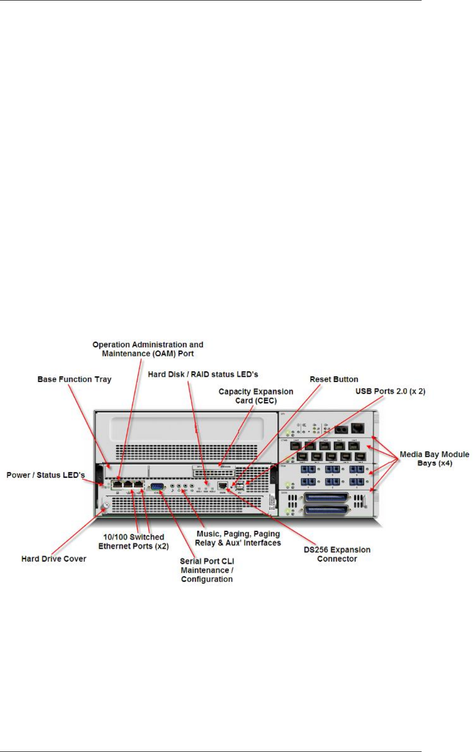
The BCM450 system is a complete, converged voice platform that provides an
expandable main chassis to the BCM portfolio of products. The system
incorporates an enhanced base function tray, a capacity expansion card
(CEC) and 80 Gigabyte hard drive with easier access for field replacement.
The main unit also provides four bay slots for housing Media Bay Modules.
The base function tray provides additional connections for auxiliary equipment
including an auxiliary ringer, page relay, page output and music source. It also
provides network connection capability having two LAN ports and an OAM
port for operation, administration and maintenance access.
The BCM450 system can link to a single BCM450 expansion unit to house
additional media bay modules and therefore offer increased capacity for lines
and extensions.
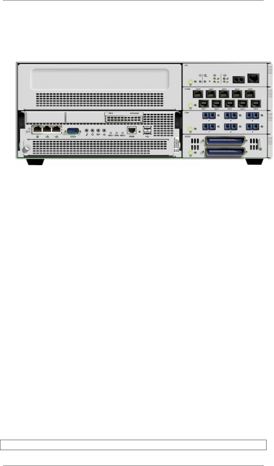
BCM450 Base Platform
BCM450 Hardware & Installation
NN40011-001 Issue 1.2 BCM450 Rls 6.0 7
The BCM450 hardware has the following primary components:
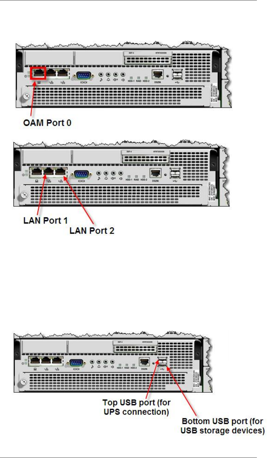
1 x Dedicated OAM Port for running Element Manager
2x RJ45 LAN Ports to connect the BCM to the customers LAN
2 x USB 2.0 ports (compatible with USB 1.1): used to connect USB
storage devices or the data interfaces for an uninterruptible power
supply (UPS) to the main unit. You must format the USB storage
device for the FAT32 file system. If necessary, reformat the USB
storage device by plugging it into a USB port on your computer, right-
clicking the USB device icon, and selecting FAT32 reformatting. This
destroys any data on the USB.
The top USB port can only be used for connecting a UPS, where as
the bottom port can be used for connection USB storage devices.
BCM450 Hardware & Installation
8 NN40011-001 Issue 1.2 BCM450 Rls 6.0
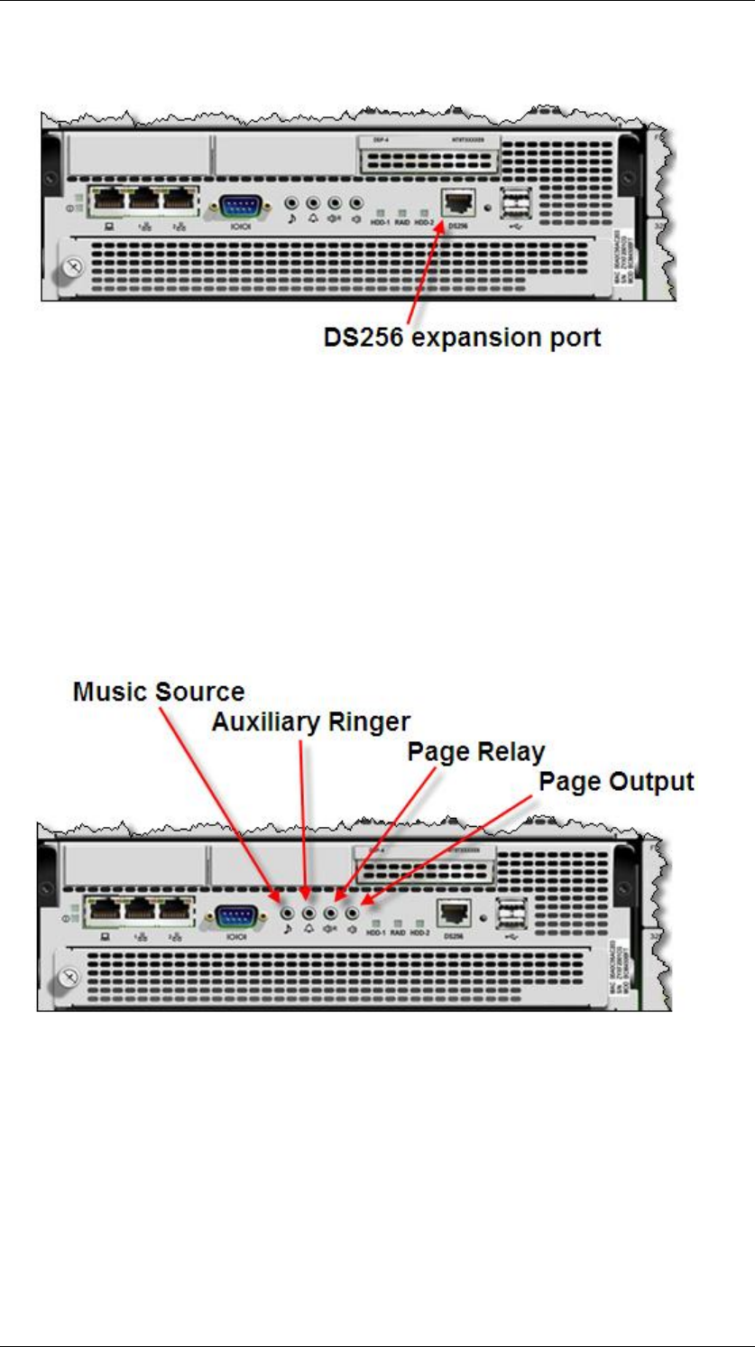
One DS256 jack to connect the BCM expansion unit to the BCM450
main chassis.
One auxiliary ringer jack to control an auxiliary ringer device.
(Customer Supplied). You must use this output in a low current, low
voltage application only. Do not use this output to directly switch the
auxiliary ringer.
A page relay jack used to control an external paging amplifier.
(Customer Supplied). If you use the page signal output jack to connect
an external paging amplifier, you also use the page relay jack. The
page relay jack connects a floating relay contact pair. The BCM450
system uses this jack to control the external paging amplifier.
A page output port for generating a paging signal to an external paging
amplifier (customer supplied).
Music on hold input support through the front panel jack.
BCM450 Hardware & Installation
NN40011-001 Issue 1.2 BCM450 Rls 6.0 9
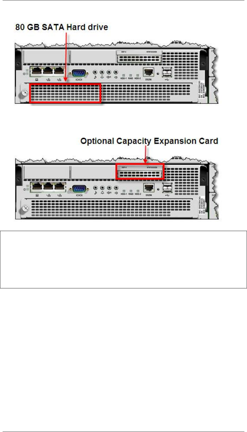
Hard Disk: 80GB SATA located at front of unit for easy access
Optional Capacity Expansion Card: Increases the capacity of the
BCM450 system to a maximum of 300 telephone stations and 130
trunks.
Note: The BCM450 supports a maximum of 300* Phones (set DN‘s). The 300
phones can comprise analog, digital and IP handsets. The system can also
have a maximum of 130* trunks that can be combination of analog, digital
physical trunks and IP Trunks. The range of Target Lines available on the
BCM 450 is 361 to 999.
*A Capacity Expansion Card is required to reach the maximum system
capacity.
Available Features
BCM450 provides a full set of telephony features and applications, some of
which are enabled through the activation of keycodes.
A full set of core telephony features consistent with the BCM portfolio
Business Series Telephones including Doorphone
Analog station terminals, including phones and fax machines
IP phones, such as IP 2000 series, IP 1100 series, IP 1200 series
phones, i2050 softphone and WLAN IP Handsets
A V.34 soft modem that replaces the V.92 hard modem of previous
release BCM platforms
BCM450 Hardware & Installation
10 NN40011-001 Issue 1.2 BCM450 Rls 6.0
IP telephony features
BCM450 offers the complete range of IP telephony features currently provided
in the BCM450 product line:
G.711 and G.729 codecs with echo cancellation
H.323 VoIP trunking
SIP VoIP trunking
BCM450 Main Unit Field Replaceable Items
Main Unit itself
Power Supply
Base Function Tray
Hard Disk Drive
Media Bay Modules (4 in Main Unit)
Optional capacity expansion card (CEC)
Fan
Memory
BCM450 Additional Components
In addition to the main platform, the following component is available:
BCM450 Expansion Unit
This unit is designed to accommodate up to 6 additional media bay modules
(MBM).

BCM450 Hardware & Installation
NN40011-001 Issue 1.2 BCM450 Rls 6.0 11
Redundancy Options
The BCM450 supports the following Redundancy options for backup/failover
purposes:
RAID Hard Disk
Fan
Power Supply
The above items can be installed in the BCM450 chassis, if they are not
already installed in the factory supplied chassis. Refer to the BCM450
Redundancy Guide for information concerning the installation of these items.
Chassis Interface Card
BCM200 & 400 models can be upgraded to BCM200/400 Rls 5.0 by swapping
the existing Base Function Tray and hard drive for a BCM450 BFT and hard
drive. Due to the physical chassis differences between the BCM200/400 and
BCM450 Base Function Trays, a Chassis Interface Card is required to allow
this upgrade.
For full instructions detailing this upgrade procedure, refer to the Upgrading
from a BCM200/400 Guide.
Upgraded BCM200 and 400 systems are termed BCM200 Rls 6.0 and
BCM400 Rls 6.0 respectively. BCM400 Rls 6.0 systems are equivalent to
BCM450 Rls 6.0 systems in the respect that both provide 4 Media Bay Module
slots and can connect to the Expansion Cabinet. BCM200 Rls 6.0 systems will
still provide 2 Media Bay Modules, but will offer the enhanced functionality of
connection to the Expansion Cabinet.
BCM450 Hardware & Installation
12 NN40011-001 Issue 1.2 BCM450 Rls 6.0
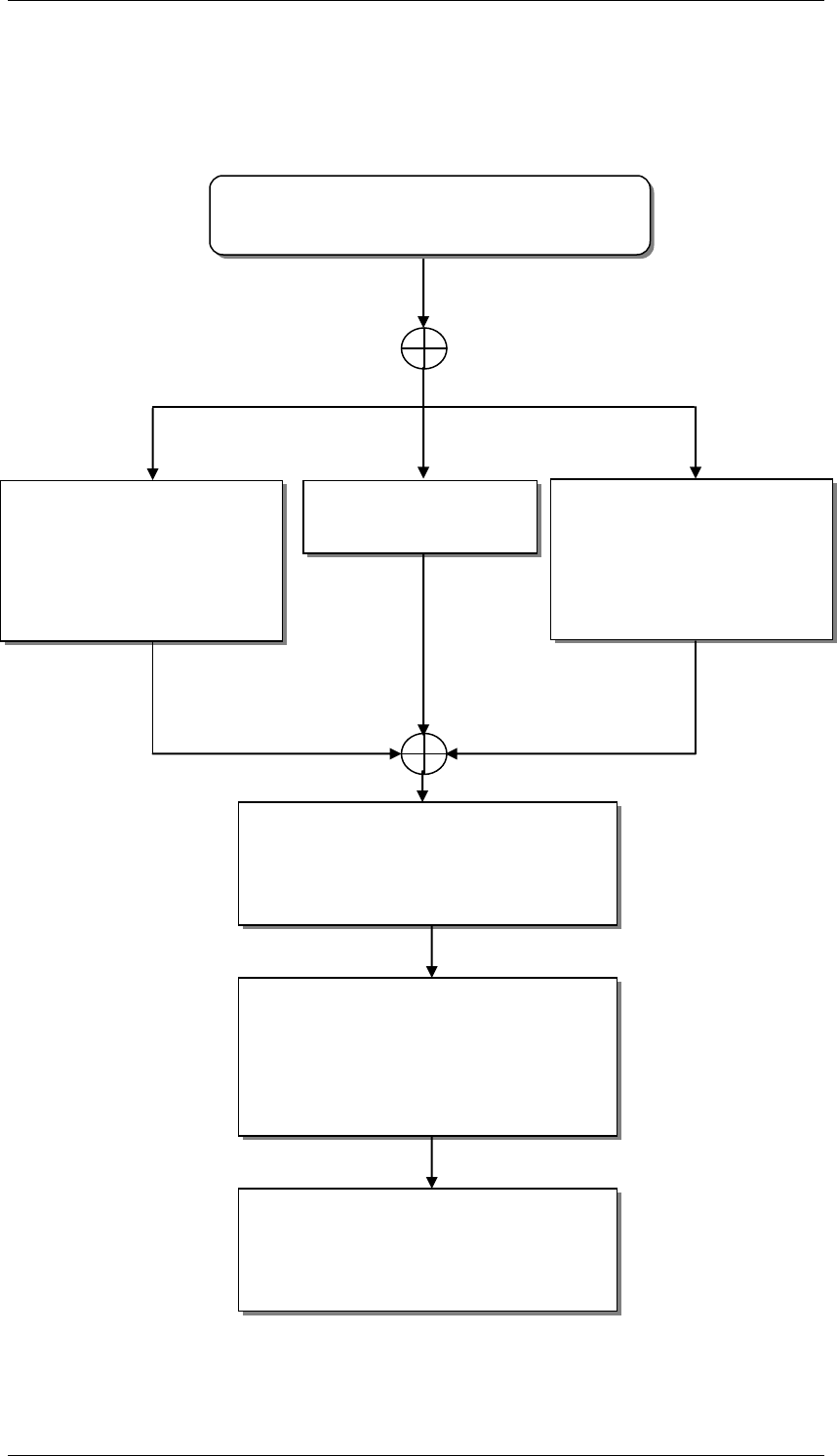
Flow Chart
The flow chart below describes the BCM450 installation process.
Install the BCM450 in a
rack: refer to the
Installing the BCM450
in an Equipment Rack
section of this guide.
Where is the BCM450 being
installed?
Apply the supplied
rubber feet.
Install wall mount
bracket: refer to the
Installing the BCM450
Wall Mount Bracket
section of this guide.
Rack
Wall mount
Desk mount
Install the Expansion Unit if
required: refer to the Installing a
BCM450 Expansion Unit
section of this guide.
Connect the BCM main unit /
Expansion Unit to a power
source: refer to the BCM450
Power Source Connections
section of this guide.
Power up the BCM / Expansion
Unit: refer to the Powering Up
the BCM section of this guide.
BCM450 Hardware & Installation
NN40011-001 Issue 1.2 BCM450 Rls 6.0 13
Wall Mount Brackets
If the BCM450 and any expansion units are to be mounted on a wall, wall
mounting brackets are required. The installation utilizing wall mount brackets
is described in detail, later in this guide.
Rack Mount Brackets
If the BCM450 and any expansion units are to be mounted in a rack, rack
mounting brackets are required. The installation utilizing rack mount brackets
is described in detail, later in this guide.
BCM450 Hardware & Installation
14 NN40011-001 Issue 1.2 BCM450 Rls 6.0
Desk Mounting the BCM450
Attach the supplied rubber feet
Position the main unit on the required desktop or shelf.
Planning the Installation
Before you install the BCM450 Main Unit or BCM450 Expansion Unit, it is
good practice to follow a preparation check as follows.
Preparation checklist:
Number of lines / handsets / ATA2‘s etc
Stores check list
Electrical requirements
Ensure you meet the following electrical requirements:
Power must be supplied from a non switchable, third-wire ground AC
electrical outlet.
If you use a power bar, connect the power cord to the power bar and
connect the power bar to the outlet.
Power must be supplied from a nonswitched, unobstructed outlet within
1.5 m (5 ft.) of the BCM450 units.
If you use a power bar, the total length of the power cables from the
power supply to the electrical outlet (including power bar) must not
exceed 2 m(6.5 ft.).
The supplied power must be a dedicated 110 V to 120 V AC nominal
(or 220 V to 240 V AC nominal), 50 to 60 Hz, 15 A minimum service
with a third-wire safety ground. The third-wire safety ground provides
shock protection and prevents electromagnetic interference.
Do not use an extension cord between the power supply and the power
bar, or between the power bar and the electrical outlet.
Danger: Risk of electric shock

BCM450 Hardware & Installation
NN40011-001 Issue 1.2 BCM450 Rls 6.0 15
Connect the ports on station modules only to approved digital telephones and
peripherals with the proper cables on a protected internal wiring system.
DANGER: Risk of electric shock
The safety of this product requires connection to an outlet with a third-wire
ground. Use only with the supplied BCM450 power cord and a three-wire
power outlet.
CAUTION: Check ground connection
Ensure that the electrical ground connections of the power utility, telephone
lines, and internal metal water pipe system, if present, are connected. If these
ground connections are not connected, contact the appropriate electrical
inspection authority. Do not try to make the connections yourself.
Caution: Use only qualified persons to service the BCM system, this includes
the installation and service of this unit. The service personnel must be aware
of the hazards of working with telephony equipment and wiring. They must
have experience in techniques that minimize any danger of shock or
equipment damage.
CAUTION : Risk of equipment damage
Service personnel must be alert to the possibility of high leakage currents
becoming available on metal system surfaces during power line fault events
near network lines. These leakage currents normally safely flow to protective
earth ground through the power cord.
System shutdown: You must disconnect the media bay module cables from
the system before you disconnect the power cord from a grounded outlet.
System startup: You must reconnect the power cords to a grounded outlet
before you reconnect the cables to the media bay modules.
Environment Checklist
The installation area must be:
Minimum of 4 m (13 ft) from equipment such as photocopiers,
electrical motors and other equipment that produces
electromagnetic, radio frequency and electrostatic interference
Within 1.5 m (5 ft.) of a three-wire grounded electrical outlet
Clean, free of traffic and excess dust, dry and well ventilated
Within the temperature ranges of 0°C and 40°C (32°F and 95°F)
Between 20% and 80% non-condensing relative humidity
Enough space and strength to support the BCM base unit
Minimum of 46 cm (18 in.) from the floor
Note: The installation area must be of sufficient height from the floor to
prevent water damage.
You also need the following equipment to install a BCM450 unit:
BCM450 Hardware & Installation
16 NN40011-001 Issue 1.2 BCM450 Rls 6.0
mounting hardware (either a rackmount shelf, a wallmount bracket
per unit or four rubber feet per unit)
Phillips screwdriver #2
flat blade screwdriver
pliers
antistatic grounding strap
connecting tool
surge protector (recommended)
cables, 25-pair cable with RJ-21 connectors
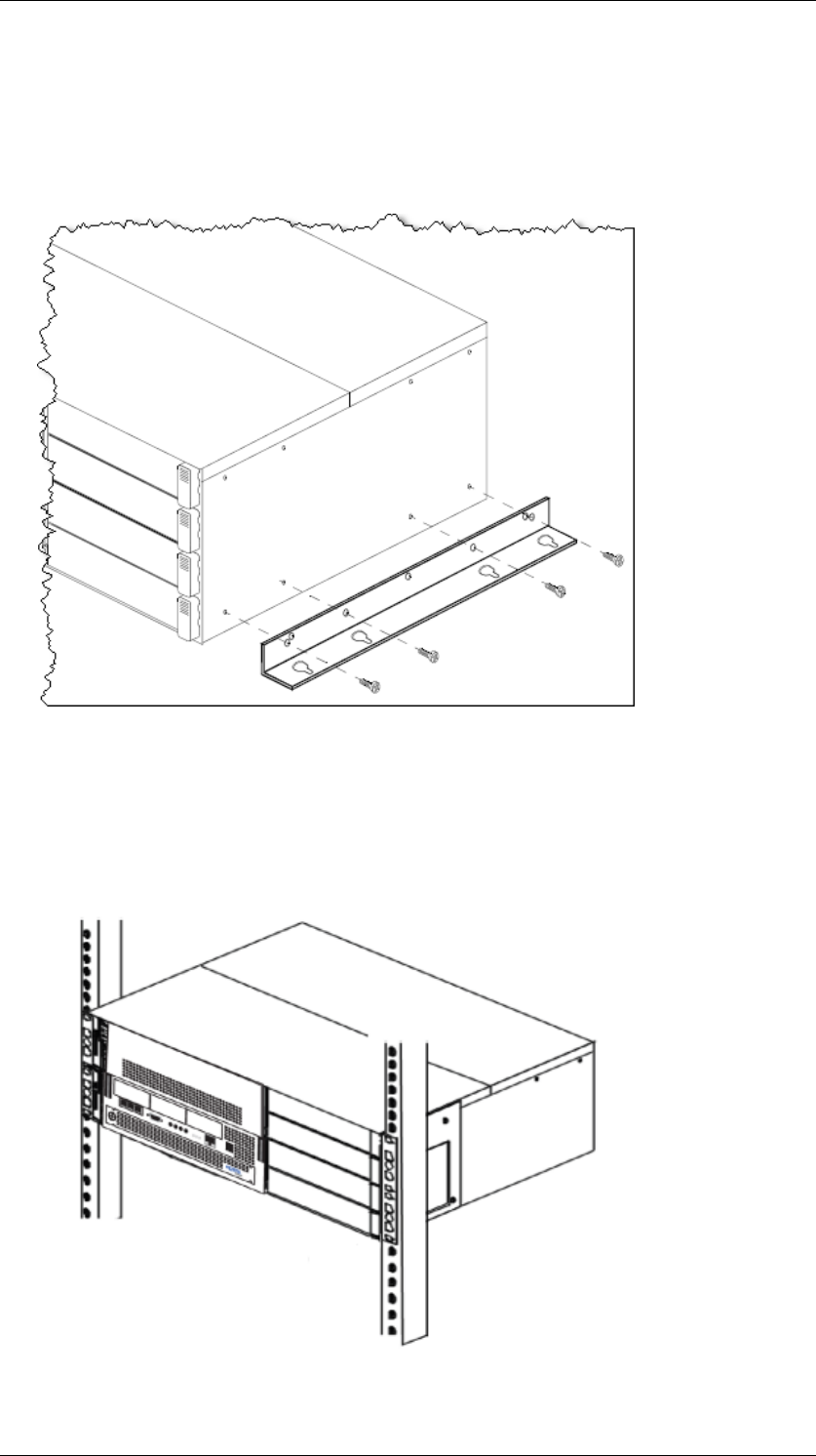
Installing the BCM450 Unit in an Equipment Rack
You can install a BCM450 main unit in a standard 19-inch equipment rack
along with your other networking and telecommunications equipment. The
BCM450 expansion unit can also be installed in the same rack.
Note: When you install the main unit in a rack, do not stack units directly on
top of one another. Mounting brackets cannot support multiple units. Fasten
each unit to the rack with the appropriate mounting brackets.
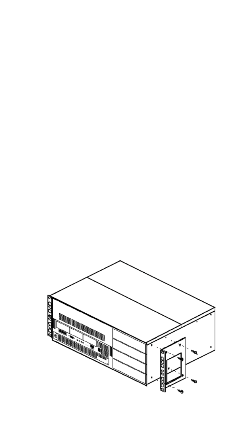
1. Place the BCM450 main unit on a flat, clean surface.
2. Take the right rack mount bracket and align the screw holes between
the bracket and the BCM450.
3. Fasten the bracket to the BCM450 main unit using four screws
provided. Use only the screws supplied with the rack-mount bracket.
Other screws can damage the BCM450 main unit.
4. Repeat the procedure with the left rack-mount bracket.
BCM450 Hardware & Installation
NN40011-001 Issue 1.2 BCM450 Rls 6.0 17
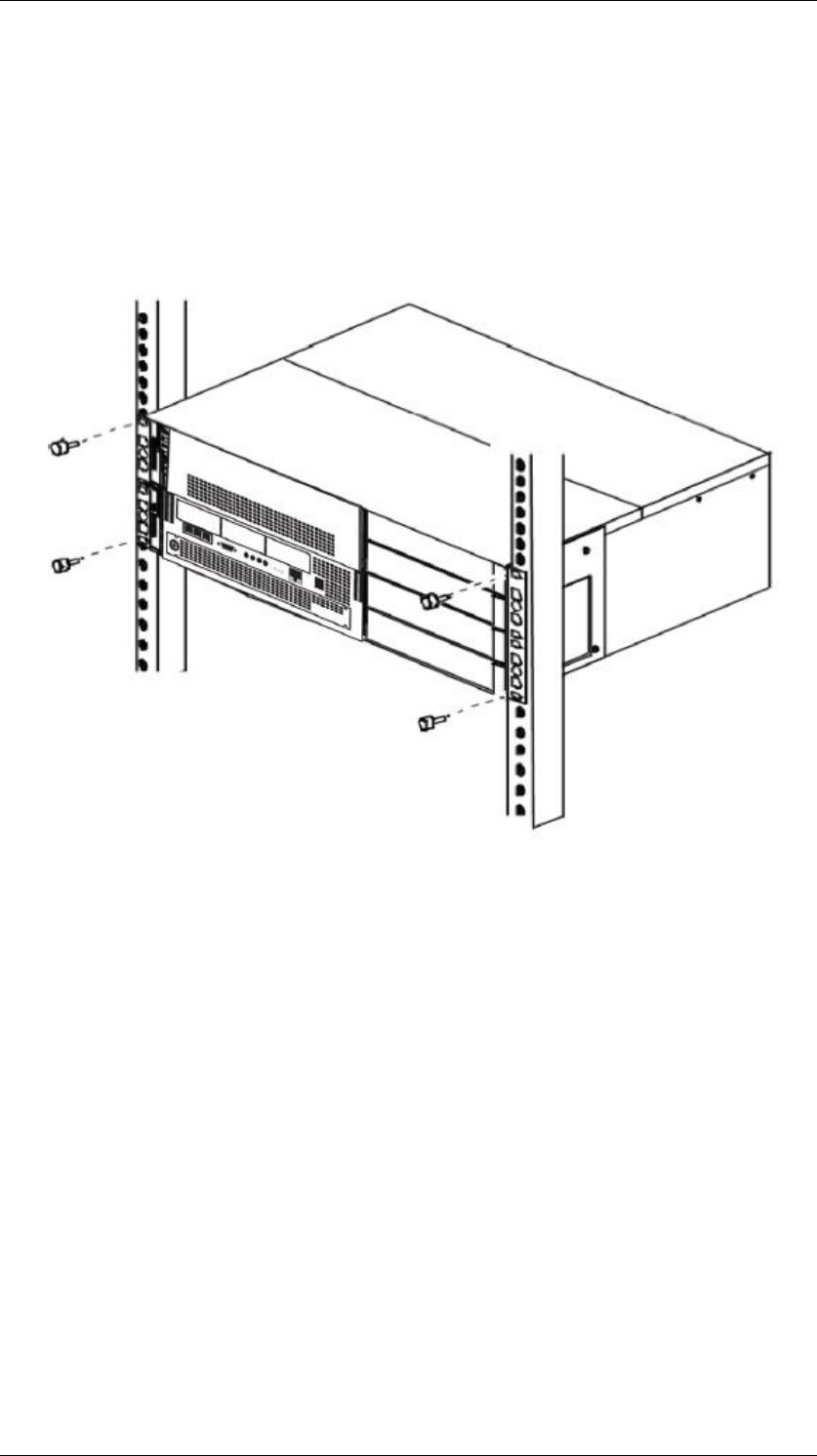
5. Position the main unit in the rack. You may require assistance to do
this.
6. Align the holes in the rack-mount bracket with the holes in the rack‘s
rails.
7. Fasten the rack-mount brackets to the rack using the four supplied rack
screws. The BCM450 will be secured in the rack.
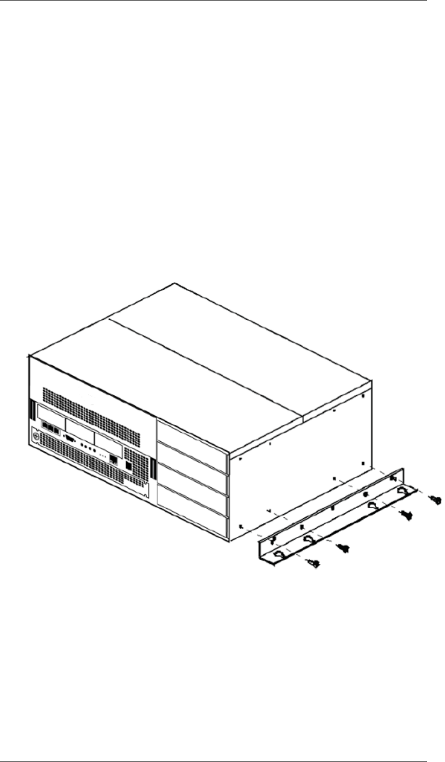
Installing the BCM450 utilizing a Wall Mount Bracket
To attach a BCM450 unit or expansion unit to a wall, you need a wall-mount
bracket for each unit. You will also need four #10 x 2.5cm (#10 x 1in.) round-
head wood screws and a plywood backboard 2 cm (3/4 in.) thick.
It is recommended that you mount a plywood backboard on a wall to simplify
installation of your BCM450 main unit and optional expansion unit.
1. Mark the desired location of the plywood backboard on the wall.
2. Use a ruler and a level and ensure that the plywood backboard is level.
3. Secure the plywood backboard to the wall with appropriate screws.
4. Place the wallmount bracket on the backboard and mark the location of
the center keyhole-shaped screw hole on the plywood backboard.
BCM450 Hardware & Installation
18 NN40011-001 Issue 1.2 BCM450 Rls 6.0
5. Install four #10 x 2.5 cm (#10 x 1 in.) round-head screws in the
backboard. Leave approximately 0.5 cm (0.25 in.) of each screw
exposed from the backboard (or wall).
6. Hang the wall-mount bracket on the screws and ensure that the wall-
mount bracket is level.
7. Remove the wall-mount bracket from the backboard.
8. The wall mount bracket can now be attached to the BCM450 unit.
9. Align the screw holes on one side of the BCM450 main unit with the
wall-mount bracket.
10. Fasten the wall-mount brackets securely to the BCM main unit using
only the screws supplied with the wall-mount bracket kit. If any other
screws are used they can damage the BCM450.
11. Hang the BCM main unit on the backboard screws. Make sure the main
unit is level.
12. Ensure the screw heads seat fully into the wall-mount bracket slots.
13. Tighten the wood screws against the wall-mount bracket.

BCM450 Hardware & Installation
NN40011-001 Issue 1.2 BCM450 Rls 6.0 19
Media Bay Modules
Media Bay Modules are installed in the BCM450‘s main unit to provide trunk
and extension capability. They can also be installed in the BCM450‘s
expansion unit to increase the Trunk and Extension capacities of the BCM.
Each Media Bay Module has a series of dipswitches located on the rear of the
unit. The dipswitches should be set as detailed in the BCM450 Media Bay
Modules Guide.
Note: For full details of Media Bay Module assignment, installation, and
configuration, please refer to the BCM450 Media Bay Modules Guide.
Supported Media Bay Modules
The following Media Bay Modules are supported on the BCM450:
Digital Trunk Modules:
o DTM (digital trunk module)
o BRI (ISDN Basic Rate trunk module)
Analog Trunk Modules
o CTM4/8 (4/8-port analog CLID trunk module)
o GATM4/8 (global 4/8-port analog trunk module)
o ADID4/8 (4/8-port analog direct inward dial)
Digital Station Modules
o DSM16(+)/32(+) (16/32-port digital station module)
Analog Station Modules
o ASM8/8+ (8-port analog station interface)
o GASM8 (global 8-port analog station interface)
Combination Modules
o 4/8x16 Combo (4/8 analog trunks, 16 digital stations,
combination of CTM4/8 & DSM16)
o G4/8x16 Combo (global 4/8 analog trunks, 16 digital stations,
combination of GATM4/8 & DSM16)
Special Modules
o FEM (Fibre Expansion Module, connects legacy Norstar
expansion modules to the BCM)
o R2MFC
Media Bay Module Descriptions
The following sections describe the hardware attributes and functionality of
the Media Bay Modules.
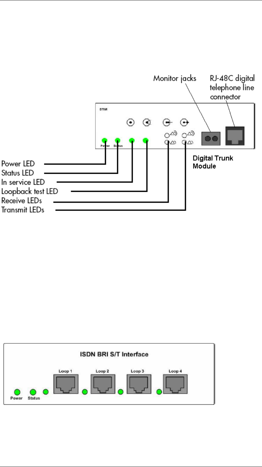
Digital Trunk Modules
When configured on a North American BCM system, the DTM connects a T1
or PRI circuit to the BCM system; T1 circuits provide 24 digital channels to the
PSTN, while PRI circuits provide 23 digital channels to the PSTN.
When configured on an International BCM system, the DTM connects an ETSI
ISDN (E1) or PRI (E1) circuit to the BCM system, providing a maximum of 30
digital channels to the PSTN.
BCM450 Hardware & Installation
20 NN40011-001 Issue 1.2 BCM450 Rls 6.0
The DTM module supports the following protocols:
PRI
DASS2
DPNSS
Basic Rate Interface Media Bay Module
The Basic Rate Interface Media Bay Module (BRIM) connects a maximum of
four BRI ISDN loops to the BCM system. Each ISDN loop supports 2
channels.
The BRIM only recognizes the T-interface used in European networks. To use
the BRIM with the U-interface, typical in North American networks, you require
an external NT1 box to convert the U-interface to a T-interface.
Each BRI ISDN connected loop adds two telephone lines to the BCM system.
Each BRIM can add a maximum of eight lines to the BCM system through the
four RJ-48C jacks on the faceplate.
BCM450 Hardware & Installation
NN40011-001 Issue 1.2 BCM450 Rls 6.0 21
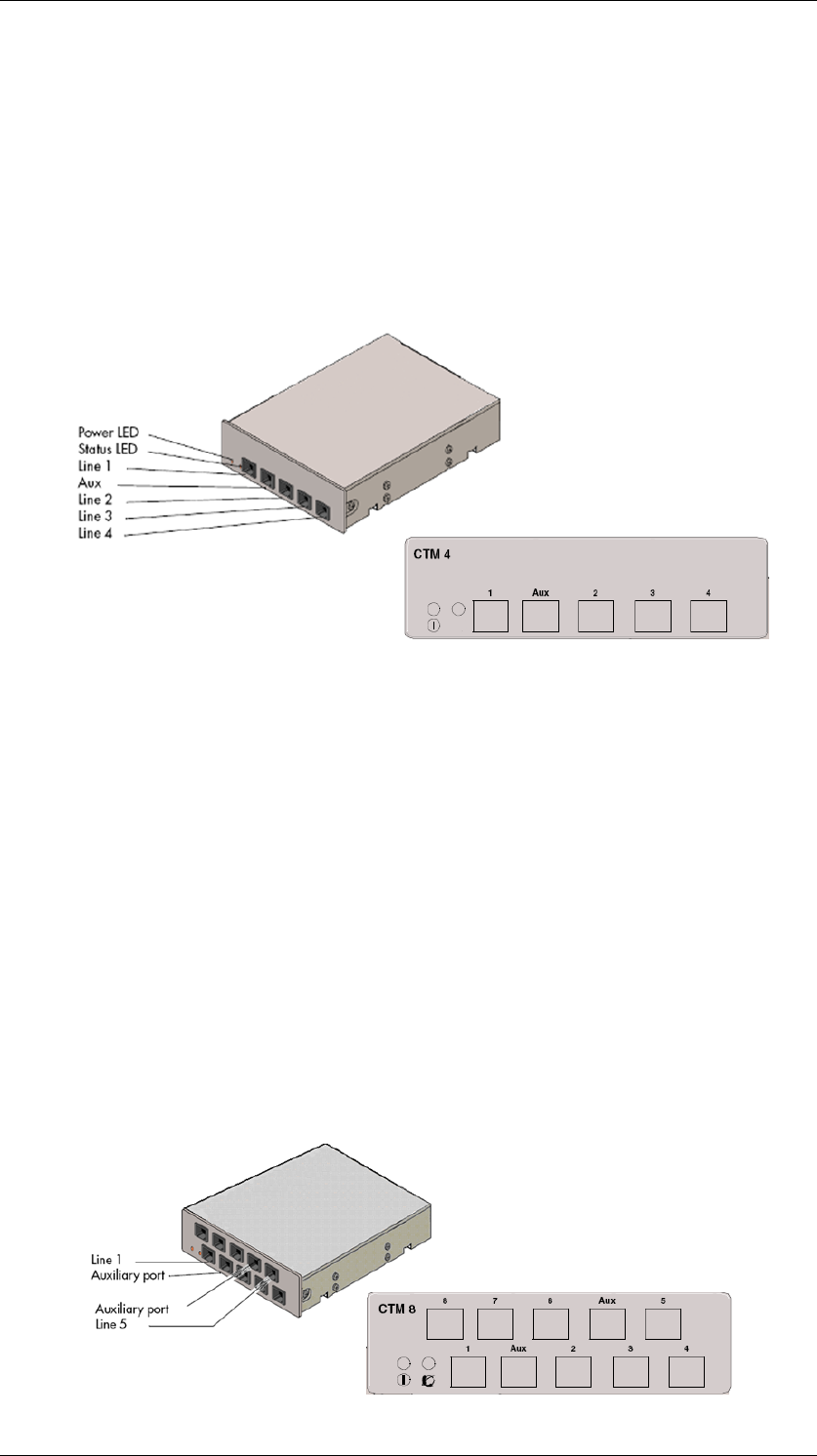
Caller ID Trunk Media Bay Module
There are two types of Caller ID trunk media bay modules (CTM):
1. CTM4:
The CTM4 connects a maximum of four analog calling line ID (CLID)
interfaces to the BCM system through four RJ-11 jacks on the front
faceplate of the MBM. These jacks are labelled Line 1,Auxiliary, Line
2, Line 3, and Line 4. The auxiliary jack connects to Line 1.
2. CTM8:
The CTM8 provides eight analog CLID interfaces to the BCM system
through eight RJ-11 jacks on the front faceplate of the BCM. Each jack
also supports disconnect supervision. There are two auxiliary jacks on
this MBM which connect to Line 1 and Line 5.
The auxiliary ports will interface to a V.92 or V.90 modem, fax machine
unit, or analog telephone. When the auxiliary device is active, the BCM
system disables the associated line. If the line is active, the auxiliary
port line is disabled.
When an analog telephone is connected to the auxiliary port, it can be
used as an emergency telephone because this line remains active
during a power outage.
BCM450 Hardware & Installation
22 NN40011-001 Issue 1.2 BCM450 Rls 6.0
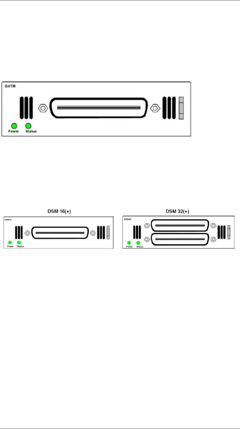
Global Analog Trunk Media Bay Module
The Global Analog Trunk Media Bay Module (GATM) provides an interface for
four or eight analog public switched telephone network (PSTN) lines. The
GATM supports both pulse and tone dialing, as well as caller ID and
disconnect supervision in selected markets throughout the world.
The GATM uses an RJ-21 connector as the trunk interface.
Digital Station Media Bay Module
The Digital Station Media Bay Modules (DSM) support digital telephones on
the BCM system.
DSM16(+): supports 16 digital telephones through one RJ-21 connector.
DSM32(+): supports 32 digital telephones through two RJ-21 connectors.
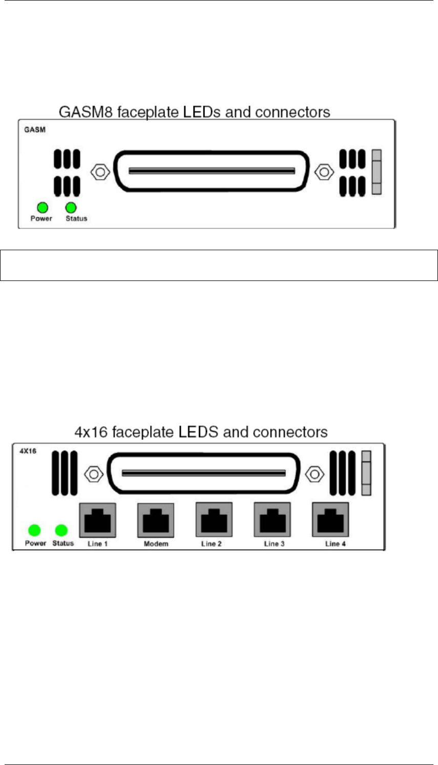
Analog Station Media Bay Modules
The Analog Station Media Bay Modules (ASM, ASM8, ASM8+, and GASM8)
can connect to a maximum of eight analog telecommunication devices. These
devices are standard analog telephones, cordless telephones, fax machines,
answering machines, or modems.
In addition to ASM8 features, the ASM8+ and GASM8 offer the following
features:
Visual Message Waiting Indicator (VMWI) — LED indicates that a
message is waiting.
Disconnect supervision (Open Switch Interval [OSI] as per EIA/TIA
464). Indicates to the attached device, in an established
communication, that the connected device should release the call
Caller ID — provides the name, phone number, and other information
about the caller to the end user telephone at the start of the call.
Firmware downloading capability — allows the system to upgrade the
ASM8+ and GASM8 firmware.
BCM450 Hardware & Installation
NN40011-001 Issue 1.2 BCM450 Rls 6.0 23
Enhanced ringing capability — ASM8+ and GASM8 provide a ringing
voltage of 2 REN/65 V rms per port.
Calling line identification (CLID)
The GASM8 is designated as an ONS (on-premise station) port.
Note: Due to power constraints, a maximum of 2 GASM MBM‘s are supported
in the main unit. Up to 4 GASM units can be installed in the expansion unit.
4x16 Media Bay Module
The 4x16 MBM provides both analog trunk and digital telephone connections.
The 4x16 MBM provides connections for four analog lines and 16 digital
telephones. Each of the four analog lines support caller ID and disconnect
supervision. An auxiliary port next to the Line 1 port enables you to use an
analog telephony device, such as a modem, fax, or telephone, to share the
trunk.
BCM450 Hardware & Installation
24 NN40011-001 Issue 1.2 BCM450 Rls 6.0
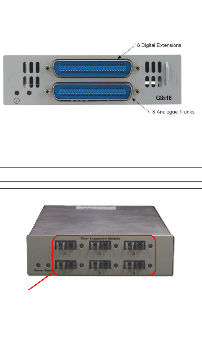
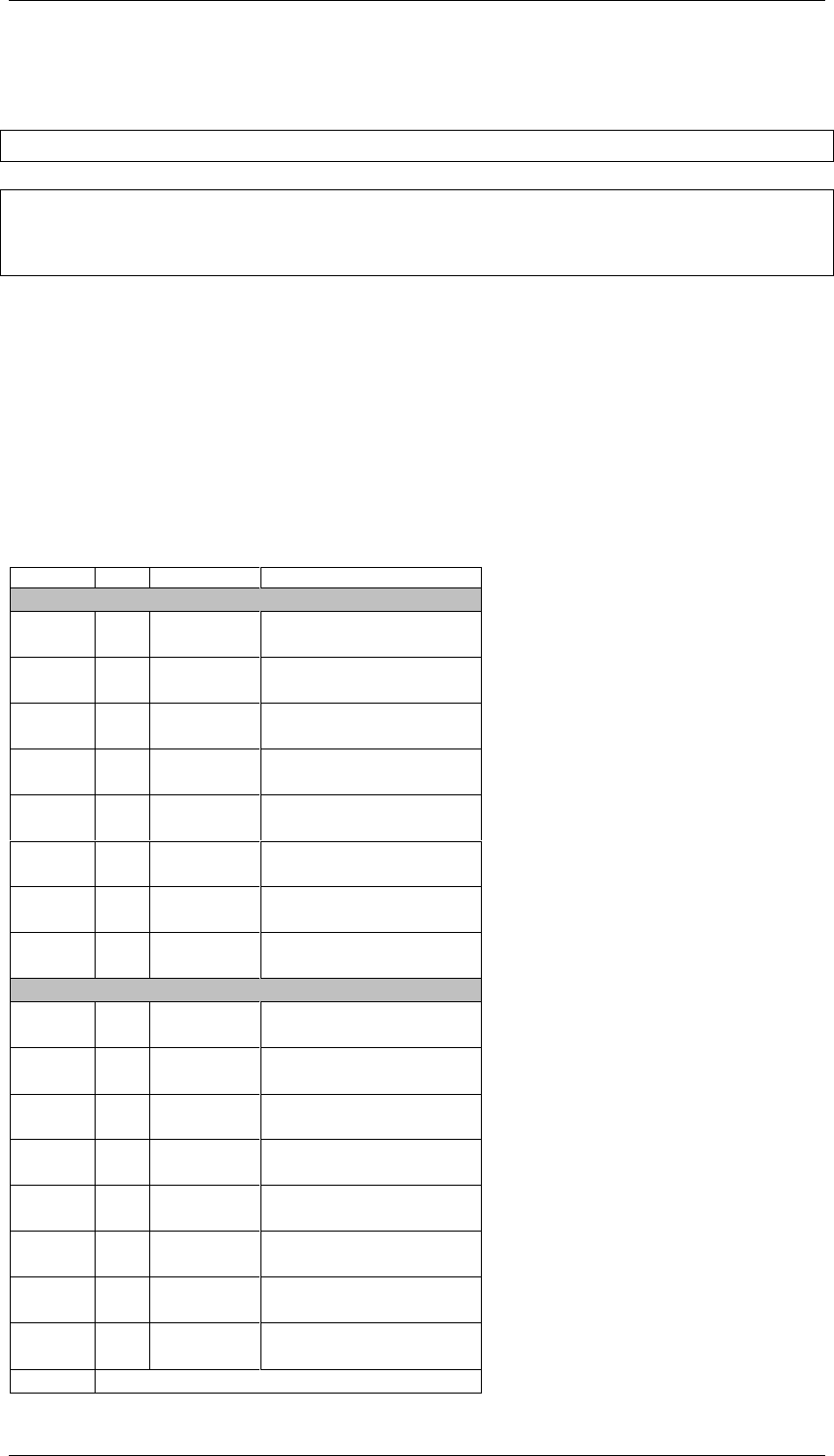
Global 4x16 and Global 8x16 Module
This is a combination module that provides 16 Digital Extensions and either 4
or 8 analog lines (version dependant).
Fibre Expansion Module
The Fibre Expansion Module (FEM) allows legacy Norstar Expansion Modules
(for connecting extensions and trunks) to be connected to the BCM450. This
would be used in installations whereby a Norstar with existing Expansion
Modules was being replaced by the BCM450. The existing Norstar Expansion
Modules would be connected via fibre cables to the fibre ports on the FEM.
Note: The FEM can only be installed in the main unit, not in the expansion
unit.
Note: Only one FEM per main unit is supported.
Up to 6 Norstar Expansion Modules can be connected via fibre cables to the
FEM. Supported Norstar Expansion Modules are:
Global Line Module (Norstar Trunk Module in Element Manager)
Extension Module (Norstar Station Module in Element Manager)
Fibre Ports – Connect to
Norstar Expansion Modules
BCM450 Hardware & Installation
NN40011-001 Issue 1.2 BCM450 Rls 6.0 25
Analog Extension Module (Norstar Analog Station Module in Element
Manager)
Note: Norstar Central Control Unit connection to the FEM is not supported.
Note: ―Daisy chaining‖ of Norstar Analog Extension Modules (AEM) is not
supported on the BCM450, i.e. only one Norstar AEM can be connected to
each FEM fibre port.
Media Bay Modules Wiring Charts
This section is for reference purposes. Wiring for the MBM‘s is provided.
ASM8(+)/GASM/DSM(+) Media Bay Module Amphenol Wiring
Use the table below if connecting extensions (stations) to a DSM Media Bay
Module.
Device
Pin
Connection
Wire Colour
ASM8/GASM/DSM
1
26
1
Tip
Ring
White-Blue
Blue-White
2
27
2
Tip
Ring
White-Orange
Orange-White
3
28
3
Tip
Ring
White-Green
Green-White
4
29
4
Tip
Ring
White-Brown
Brown-White
5
30
5
Tip
Ring
White-Slate
Slate-White
6
31
6
Tip
Ring
Red-Blue
Blue-Red
7
32
7
Tip
Ring
Red-Orange
Orange-Red
8
33
8
Tip
Ring
Red-Green
Green-Red
DSM Only
9
34
9
Tip
Ring
Red-Brown
Brown-Red
10
35
10
Tip
Ring
Red-Slate
Slate-Red
11
36
11
Tip
Ring
Black-Blue
Blue-Black
12
37
12
Tip
Ring
Black-Orange
Orange-Black
13
38
13
Tip
Ring
Black-Green
Green-Black
14
39
14
Tip
Ring
Black-Brown
Brown-Black
15
40
15
Tip
Ring
Black-Slate
Slate-Black
16
41
16
Tip
Ring
Yellow-Blue
Blue-Yellow
17 - 25
No Connection

BCM450 Hardware & Installation
26 NN40011-001 Issue 1.2 BCM450 Rls 6.0
Note: The ASM8/8+ and GASM MBM‘s support 8 analog stations.
ADID4/8 Media Bay Module Amphenol Wiring
Use the table below if connecting analog trunks to an Analog Direct Inward
Dial MBM.
Device
Pin
Connection
Wire Colour
ADID4 & ADID8
1
26
1
Tip
Ring
White-Blue
Blue-White
2
27
2
Tip
Ring
White-Orange
Orange-White
3
28
3
Tip
Ring
White-Green
Green-White
4
29
4
Tip
Ring
White-Brown
Brown-White
ADID8 Only
5
30
5
Tip
Ring
White-Slate
Slate-White
6
31
6
Tip
Ring
Red-Blue
Blue-Red
7
32
7
Tip
Ring
Red-Orange
Orange-Red
8
33
8
Tip
Ring
Red-Green
Green-Red

BCM450 Hardware & Installation
NN40011-001 Issue 1.2 BCM450 Rls 6.0 27
GATM4/8 Media Bay Module Amphenol Wiring
Use the table below if connecting analog trunks to a GATM4 or GATM8 Media
Bay Module. It is also possible to connect a power fail extension to the last
pair on the amphenol wiring.
Device
Pin
Connection
Wire Colour
GATM4 & GATM8
1
26
1
Tip
Ring
White-Blue
Blue-White
2
27
2
Tip
Ring
White-Orange
Orange-White
3 – 4
No Connection
5
30
5
Tip
Ring
White-Slate
Slate-White
6
31
6
Tip
Ring
Red-Blue
Blue-Red
GATM8 Only
7 – 8
No Connection
9
34
9
Tip
Ring
Red-Brown
Brown-Red
10
35
10
Tip
Ring
Red-Slate
Slate-Red
11 - 12
No Connection
13
38
13
Tip
Ring
Black-Green
Green-Black
14
39
14
Tip
Ring
Black-Brown
Brown-Black
15 - 24
No Connection
25
50
25
Tip
Ring
Violet-Slate
Slate-Violet
Can be used to connect a
power fail analog set. If
system power fails the set will
use line 1.
BCM450 Hardware & Installation
28 NN40011-001 Issue 1.2 BCM450 Rls 6.0
G4/8x16 Media Bay Module Amphenol Wiring
The G4/8x16 MBM‘s is a combination of the GATM4/8 and DSM16(+) Media
Bay Modules.
For the Analog Trunk wiring, refer to the GATM4/8 Media Bay Module
Amphenol Wiring section of this guide.
For the Digital Station wiring, refer to the ASM/GASM/DSM Media Bay
Module Ampenol Wiring section of this guide, consulting the DSM32 High
column(s).
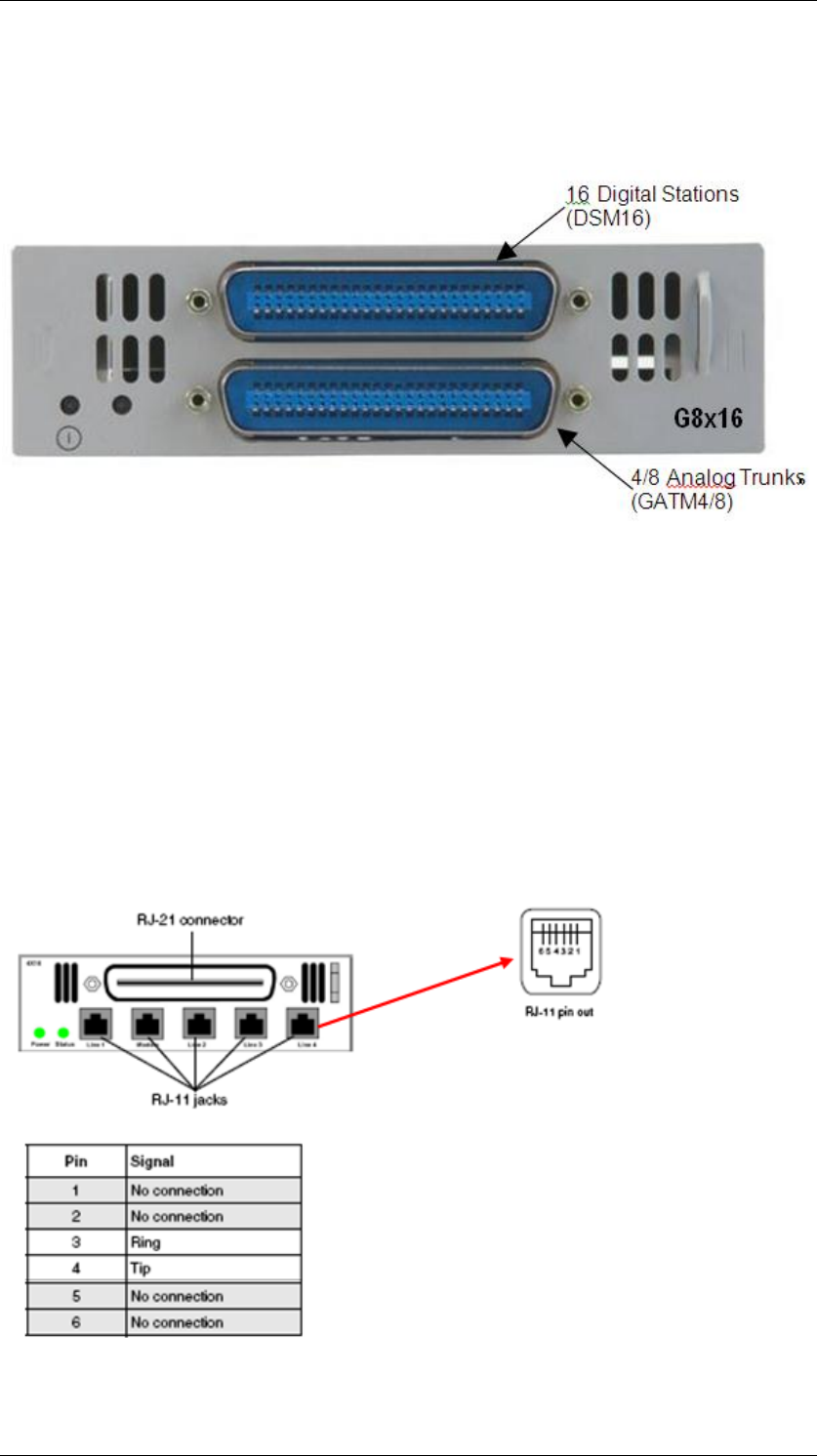
4x16 Media Bay Module Wiring
The 4x16 MBM has RJ-11 ports for connecting Analog Trunks, and an
amphenol connection for connecting the Digital Stations. The RJ-11 pin outs
are as below.

BCM450 Hardware & Installation
NN40011-001 Issue 1.2 BCM450 Rls 6.0 29
There are 4 line ports for analog trunks, and an auxiliary port next to Line port
1 designated for an emergency (power fail) phone.
For the Digital Station wiring, refer to the ASM/GASM/DSM Media Bay
Module Ampenol Wiring section of this guide, consulting the DSM32 High
column(s).
BRI Ports
The BRI Port Wiring chart below relates to the BRI Media Bay Modules.
BRI Port Wiring
BCM450 Hardware & Installation
30 NN40011-001 Issue 1.2 BCM450 Rls 6.0
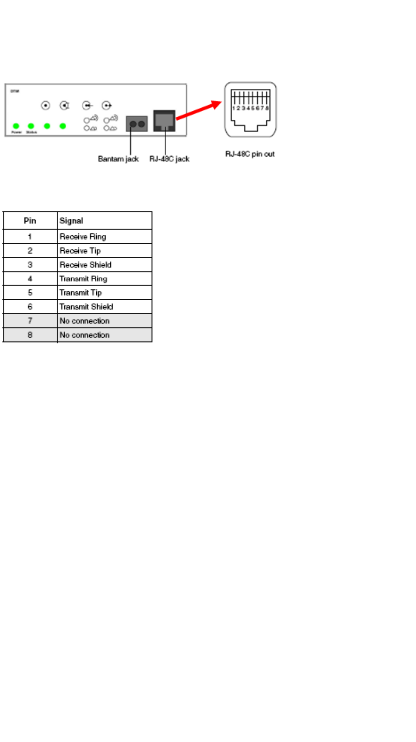
DTM Ports
The digital trunks are connected to the DTM via the RJ-48C jack.
The pin outs are detailed below.
BCM450 Hardware & Installation
NN40011-001 Issue 1.2 BCM450 Rls 6.0 31
Installing Media Bay Modules
The BCM450‘s main unit can accommodate four Media Bay Modules. If the
BCM450 system requires additional Media Bay Modules, an expansion unit
must be connected to the main unit. The expansion unit can then house the
additional Media Bay Modules.
Note: For full details of Media Bay Module assignment, installation, and
configuration, please refer to the BCM450 Media Bay Modules Guide.
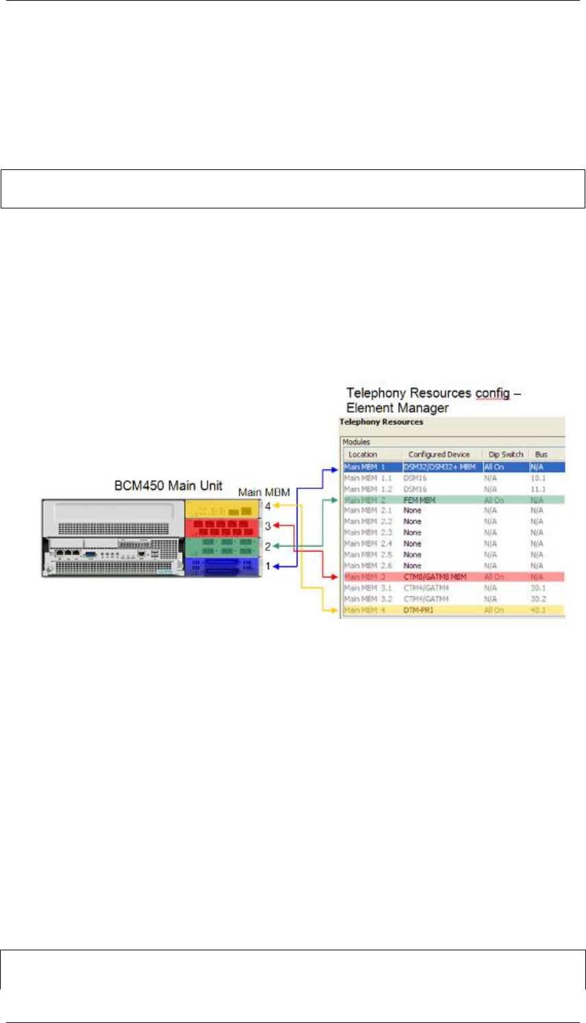
Telephony Resource allocation is determined differently depending on
whether or not MBM‘s will be installed in the BCM450 main unit or the
expansion unit (if utilising):
Main Unit: There are 4 Media Bays available, termed MBM1, MBM2,
MBM3, and MBM4. Physical location determines the Telephony
Resources location.
Main MBM 1 is pre-configured to be a DSM32(+). This is the only pre-
configured module.
Expansion Unit: There are 6 Media Bays available. Dipswitch
configuration determines the Telephony Resources location. MBM‘s
can be installed in any bay in the expansion unit.
Note: It is recommended that the Media Bay Modules (MBM‘s) are only
installed in the BCM450 main or expansion unit after they have been
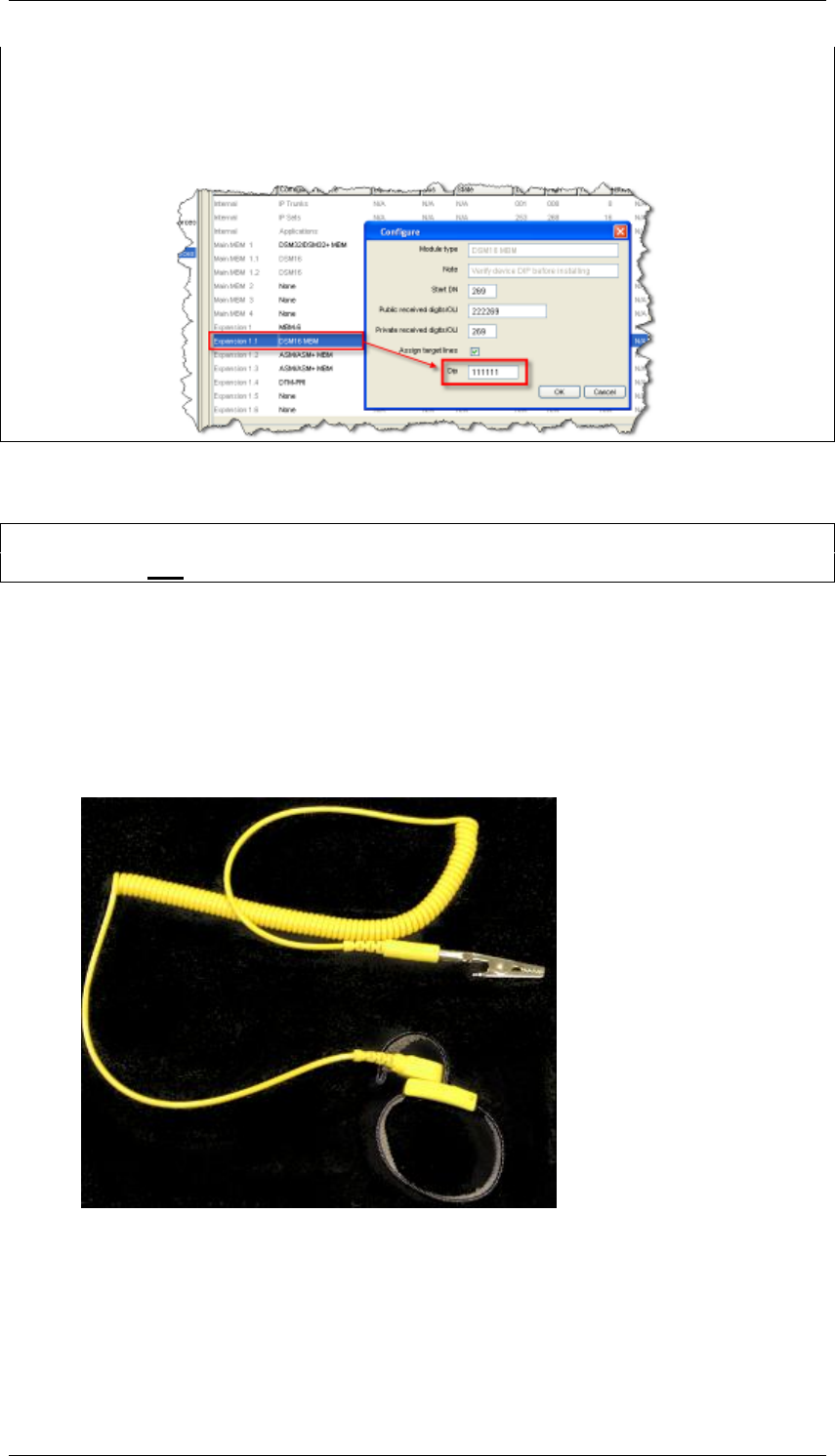
BCM450 Hardware & Installation
32 NN40011-001 Issue 1.2 BCM450 Rls 6.0
configured within Element Manager. During the MBM‘s configuration by
Element Manager, the required dipswitch settings will be displayed within the
Element Manager interface. The example below is for illustrative purposes
only with dipswitch settings that may differ from those required for your own
configuration.
Media bay modules can be installed as follows:
Note: Do not install MBM‘s whilst the BCM is powered up, as the Media Bay
Modules are not ‗hot swappable‘.
1. Verify that the Media Bay Module‘s dipswitches have been set
correctly. Please refer to the BCM450 Media Bay Modules Guide for
details.
2. Attach one end of a grounding strap to your wrist and the other end to a
grounded metal surface.
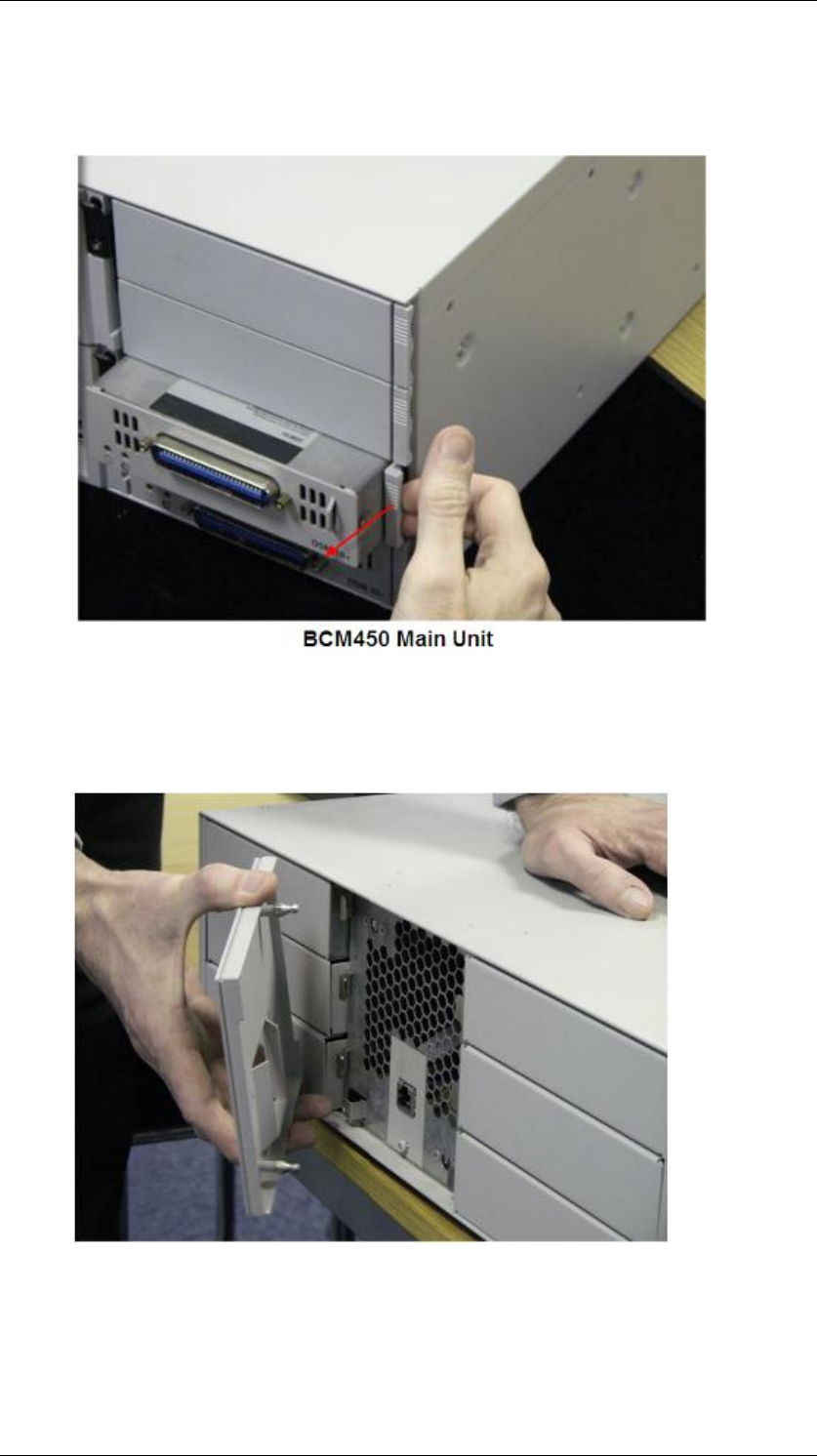
3. With the face of the MBM facing toward you, insert the MBM into the
required MBM bay on the main unit or the expansion cabinet.
BCM450 Hardware & Installation
NN40011-001 Issue 1.2 BCM450 Rls 6.0 33
4. Push the MBM completely into the MBM bay. You should hear a click
when the MBM is firmly seated in the bay. Connect the required
cabling.
5. Repeat steps 2 and 3 for each additional MBM to be installed.
Removing a Media Bay Module from the Main or Expansion
Unit.
Note: To remove a media bay module, the BCM main unit or expansion unit
must be powered down.
BCM450 Hardware & Installation
34 NN40011-001 Issue 1.2 BCM450 Rls 6.0
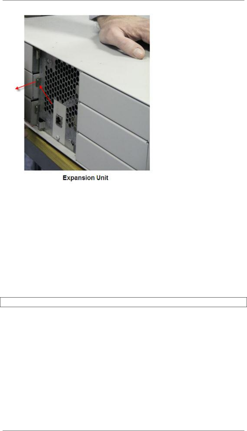
1. To remove a media bay module from the main unit, pull the lever
adjacent to the media bay module.
2. If you wish to remove a Media Bay Module from the expansion unit
remove the square panel cover positioned in the middle of the front of
the unit.
3. The media bay module can then be removed by pulling the lever
adjacent to the MBM bay.
BCM450 Hardware & Installation
NN40011-001 Issue 1.2 BCM450 Rls 6.0 35
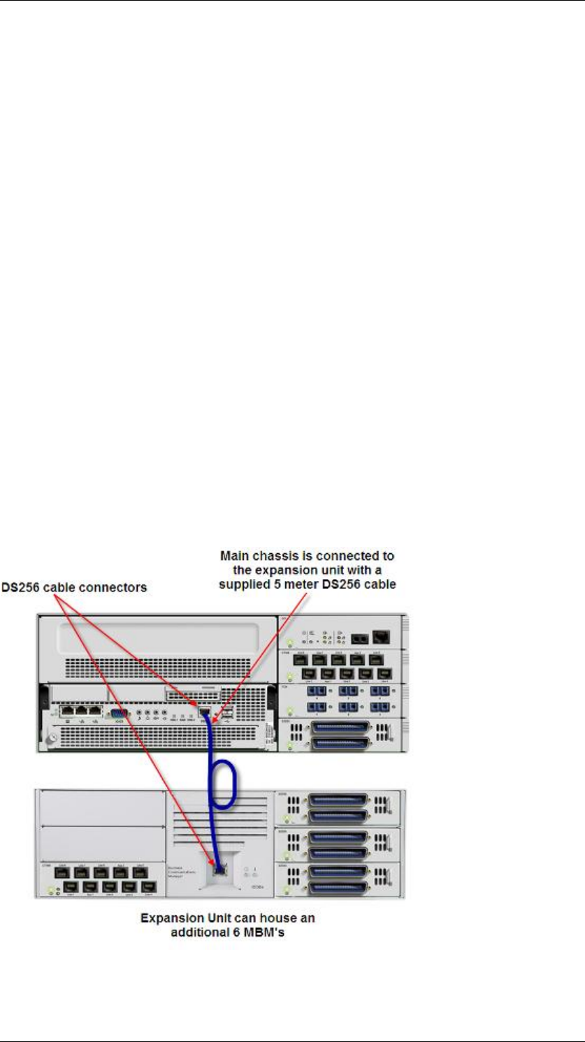
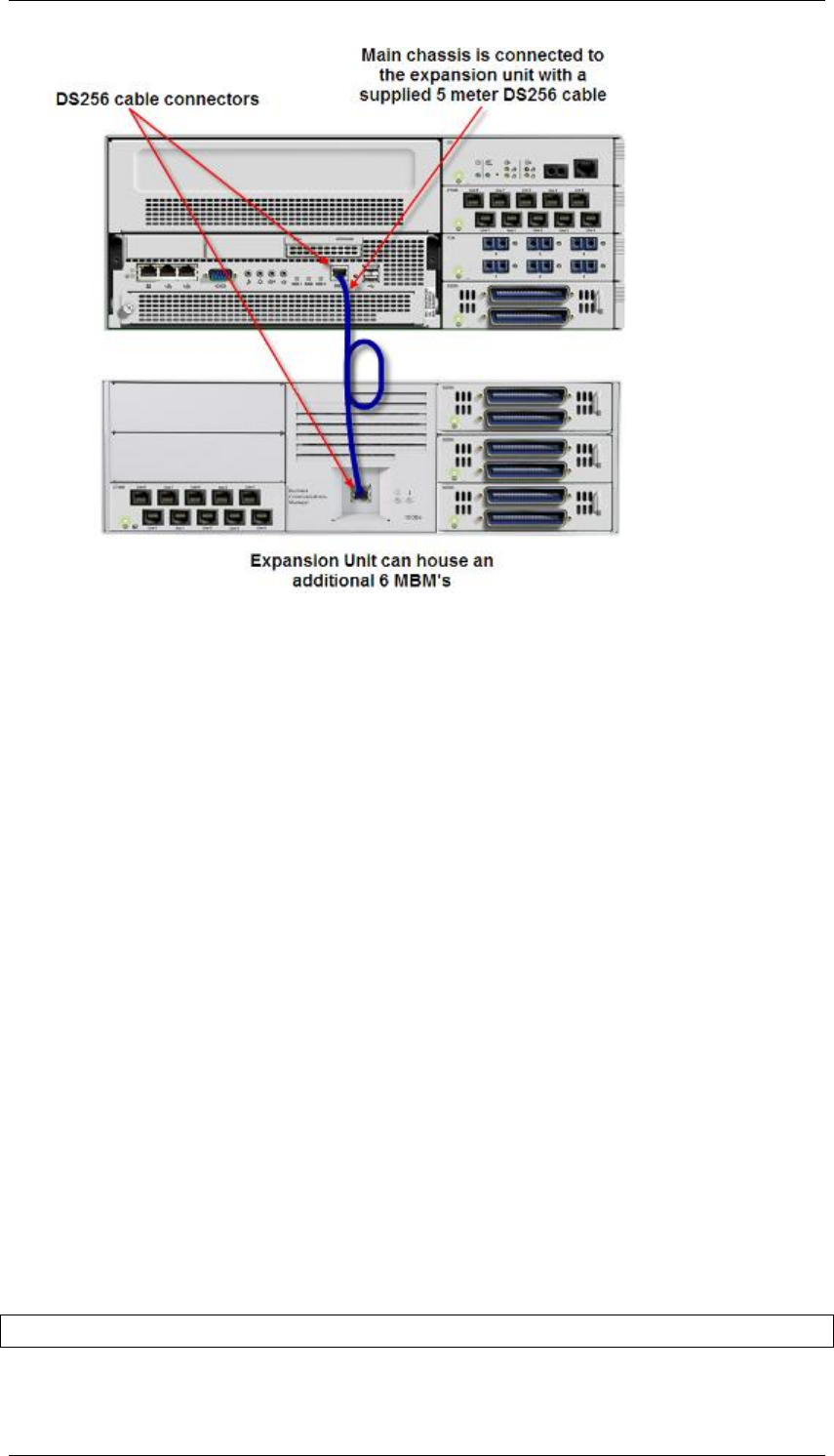
Installing a BCM450 Expansion Unit
Adding a BCM450 Expansion Unit increases the capacity of the BCM450
system by providing a method of adding additional media bay modules
(MBM). Each MBM added, increases the number of trunks or extensions that
you can connect to the BCM450 system.
The BCM450 can be connected to a maximum of 1 Expansion Unit.
Each Expansion Unit can support 6 Media Bay Module modules.
The expansion unit must be attached to the BCM450 by means of a 5
meter DS256 cable that is supplied with the expansion unit.
Note: A keycode is required to enable the expansion unit.
To connect the BCM450 expansion unit to the main unit:
1. Plug one end of the supplied DS256 cable in the DS256 connector on
the expansion unit.
2. Plug the other end of the cable into the DS256 connector on the
faceplate of the MSC in the BCM450 main unit.
BCM450 Hardware & Installation
36 NN40011-001 Issue 1.2 BCM450 Rls 6.0
The BCM main unit and expansion unit are each powered through an AC
outlet. The voltage required depends on the geographical location of the units.
You must check that the voltage and wiring are correct for your system before
you connect the units to the power source. Incorrect power settings result in
equipment damage.
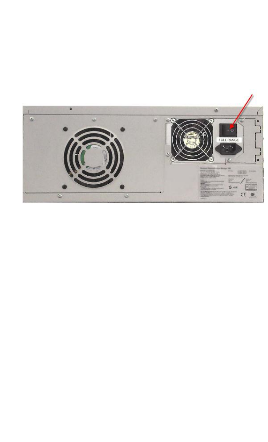
BCM450 Power Source Connections
The BCM‘s power unit connection is positioned to a rear of the chassis. The
Expansion unit‘s power connection is also positioned to the rear of the
chassis.
Connecting the BCM450 System Directly to a Power Source
To power your BCM450 systems main unit and if applicable expansion unit,
directly from an AC power source:
1. Connect the BCM and expansion unit to a non switchable, third wire
ground AC electrical outlet.
2. If a power bar is to be utilized, connect the power cord to the power bar
and then connect the power bar to the outlet.
3. If the BCM has a Redundant Power Supply, ensure both power cords
are connected to the power outlet or power bar.
Note: The power supply must be within 1.5 meters of the BCM450 main unit
BCM450 Hardware & Installation
NN40011-001 Issue 1.2 BCM450 Rls 6.0 37
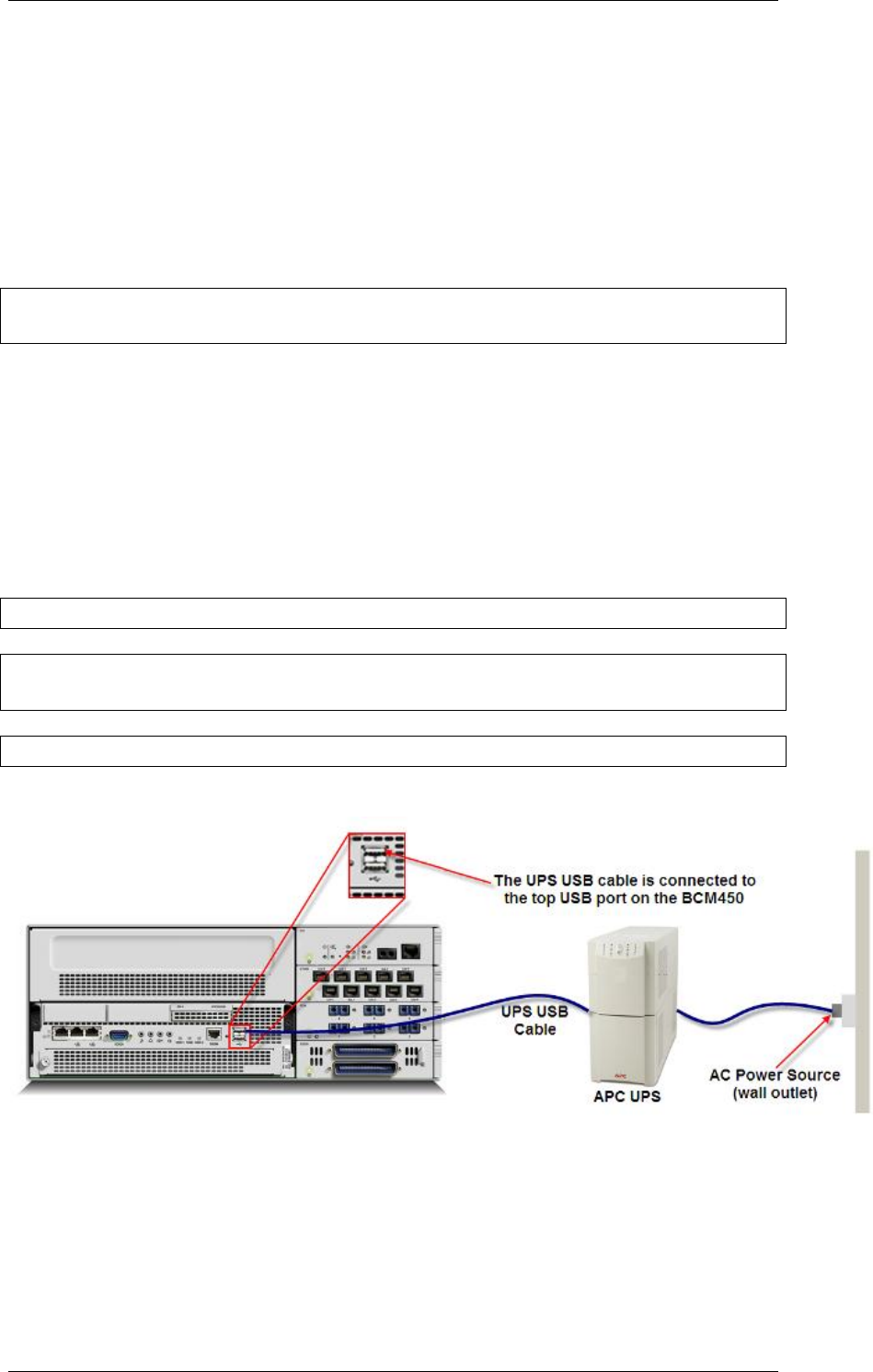
UPS and BCM450
The BCM450 system can also be powered via connection to an uninterruptible
power supply (UPS). The UPS provides battery backup for the BCM450
system to maintain continuous operation during power interruption or failure
conditions.
The connections have to be made in the correct order; otherwise the UPS will
not function correctly.
Note: The UPS must be connected before the BCM450 is powered up. If it is
connected to a running BCM system, the UPSD will not function.
To connect the UPS:
1. Plug the USB cable into the USB port of the UPS.
2. Plug the other end of the USB cable into the top USB port of the
BCM450.
3. Plug the UPS power cable into the AC power source.
Note: The power supply must be within 1.5 meters of the BCM450 main unit
Note: For Non American installations, a power supply adapter cord is required
to connect the power supply to the region specific power bar.
Note: APC is the only supported UPS vendor for the BCM
The main unit uses the data interface to enable the UPS to monitor and
control the UPS functions.
BCM450 Hardware & Installation
38 NN40011-001 Issue 1.2 BCM450 Rls 6.0
Powering Up the BCM
1. Ensure your BCM450 power supply is connected to the BCM450
system and to an AC wall outlet or a UPS.
2. Ensure the telephony cables are connected to the BCM450 main unit
and BCM450 expansion unit.
3. The BCM‘s power on / off switch is located to the rear of the unit.
4. If you have a BCM450 with a Redundant Power Supply, ensure both on
/ off switches are in the on position.
5. When the power is turned on the BCM will start the boot sequence.
Check the Power and Status LEDs on the main unit.
6. After the BCM450 starts, both LEDs must be solid green.
7. If either LED is not solid green, there is a problem with the main unit.
8. If this system has an expansion cabinet, check the Power and Status
LEDs on the media bay modules (MBM) in the expansion cabinet. Both
LEDs must be solid green. If either LED is not solid green, there is a
problem with the MBM or the expansion cabinet.
9. Once the system has powered up the system can then be configured.
LED Status
Information regarding the status of the BCM450 system can be obtained from
the LEDs that are visible on the front of the main unit of the BCM. The LEDs
can be viewed to help determine if the BCM is functioning properly and if there
are any system generated alarms.

BCM450 Hardware & Installation
NN40011-001 Issue 1.2 BCM450 Rls 6.0 39
The table below outlines the various System LED states and their
descriptions.
Power
Status
Description
LED status during Start up sequence
Solid yellow
Solid yellow
Power Applied to System
Solid yellow
Off
Power on self test (POST).
Lasts for 9 seconds.
Solid yellow
Solid yellow
System initializing (lasts 14
seconds).
Solid green
Solid yellow
Kernel initialization (lasts 8
seconds)or Safe OS.
Solid green
Flashing green
Services initializing (lasts 1
minute).
Solid green
Solid green
Normal operation.
Solid green
Solid red
Services initialization failed.
LED states seen during Safe Mode start up sequence
Solid red
Solid green
System running with factory
default settings enabled.
Solid red
Solid red
System running in Software
Reset mode
Solid red
Flashing yellow
System running in
Configuration Reset mode.
LED states seen during shut down sequence or failure
Solid green
Flashing yellow
Graceful shutdown in
progress
Off
Solid yellow
Graceful shutdown
completed
Solid red
Flashing yellow
Overheat detected. Thermal
shutdown completed
Solid red
Solid red
Power spike or Rail power
fluctuation detected.
Flashing red
Solid red
Rail Power fluctuation. Power
Monitor Shutdown completed
Solid yellow
Solid red
Power spike shutdown
completed (temperature and
Rail power ok).
Off
Off
No power, system is shut
down (power cable is
disconnected)

BCM450 Hardware & Installation
40 NN40011-001 Issue 1.2 BCM450 Rls 6.0
Power
Status
Description
Start-up Profile LED states (seen only during initial system install or staging)
Flashing Yellow
Flashing Yellow
Start-up Profile executing
Solid Green
Solid Green
Start-up Profile successfully
applied.
Flashing Yellow
Flashing Red
Start-up Profile failure.
The table below outlines the various LED states and their descriptions, in
relation to the hard disk.
LED
Description
Off
No Hard Disk Drive activity detected
Green
Normal Operation
Red
Hard Disk Drive Fault
Flashing Orange
Hard Disk Drive Activity
BCM450 Hardware & Installation
NN40011-001 Issue 1.2 BCM450 Rls 6.0 41
Additional Information
The following sections contain procedures that may not be necessary in all
installations.
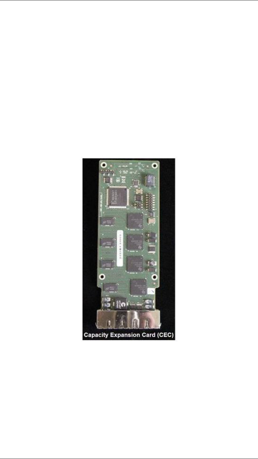
Installing a Capacity Expansion Card
The main unit of the BCM450 system supports 100 phone stations, 48 trunks
(with the exception of E1 trunks which support two DTM media Bay Modules
providing a total of 60 E1 trunks), 2 fax ports, 300 Unified Messaging Seats
and 64 conference ports.
When installed, the Capacity Expansion Card (CEC) increases the media
processing capacity on the BCM450 so that it can support up to 300 stations
and 130 trunks. It also provides an increase in the BCM‘s application capacity.
To install the CEC:
1. Check for a recent backup of the BCM450 programming. If there is no
recent backup, use Element Manager to back up of all the system data.
2. Use Element Manager to shut down the BCM450 system.
3. Power down the BCM450.
4. Disconnect the BCM450 unit from the AC power source.
BCM450 Hardware & Installation
42 NN40011-001 Issue 1.2 BCM450 Rls 6.0
5. Use a grounding strap and attach one end to your wrist and the other to
a grounded metal surface.
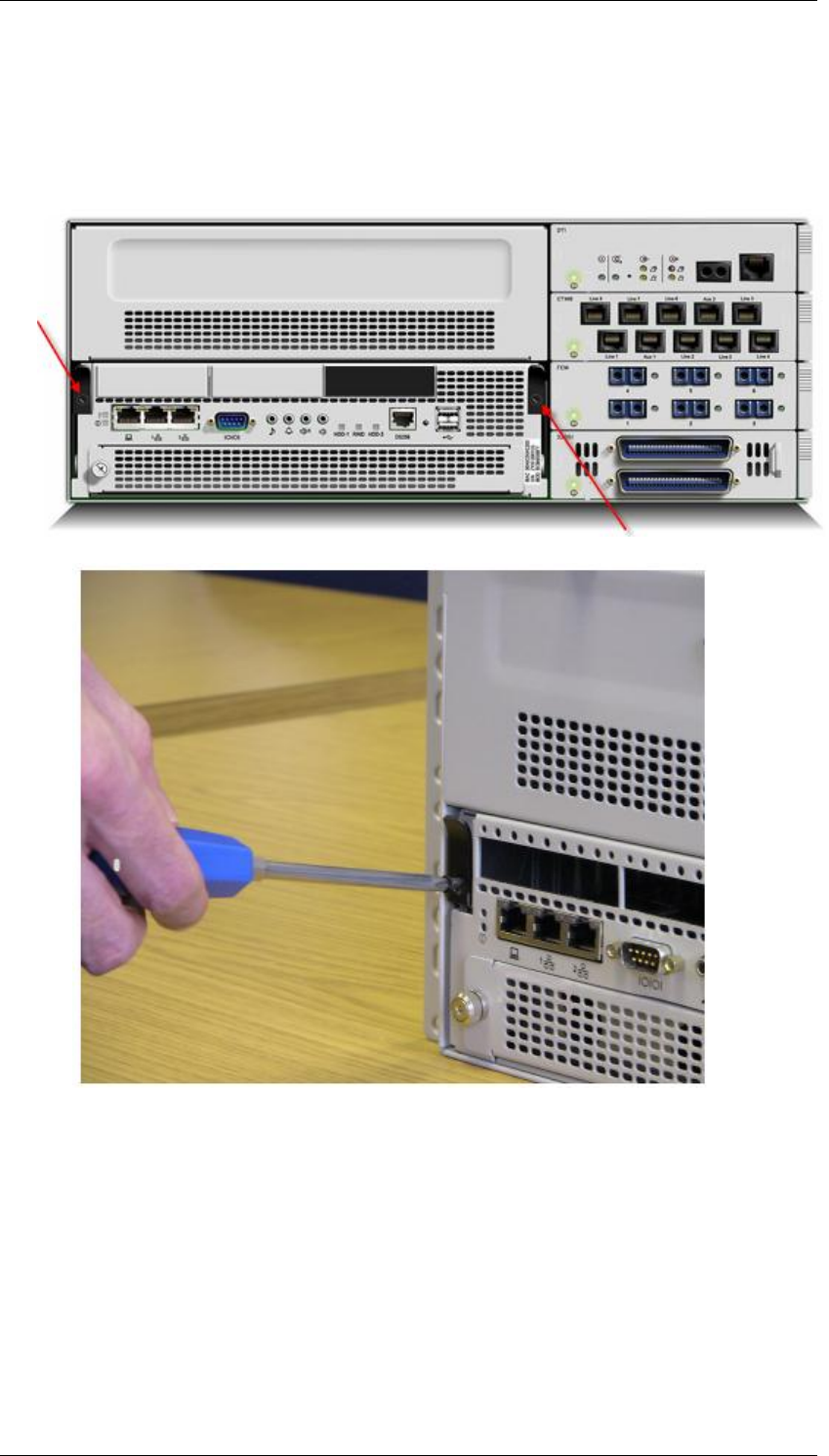
6. To gain access to the CEC slot, the base function tray (BFT) can be
removed. Remove the screws from the two BFT levers to the front of
the BCM.
BCM450 Hardware & Installation
NN40011-001 Issue 1.2 BCM450 Rls 6.0 43
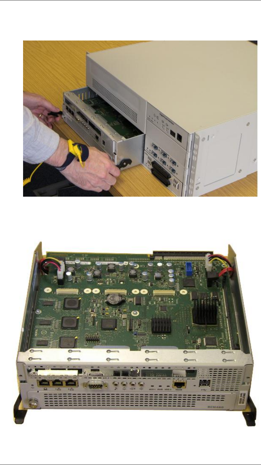
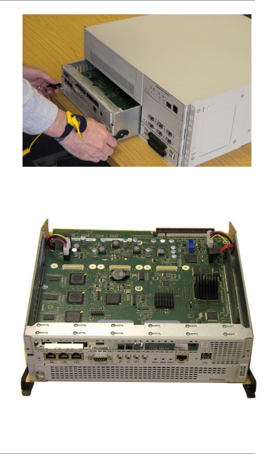
7. Pull the base function tray levers towards you, the base function tray
should move forward.
8. Hold the levers and pull the tray until it is removed from the main unit.
9. Place the tray on a clean, static free surface.
BCM450 Hardware & Installation
44 NN40011-001 Issue 1.2 BCM450 Rls 6.0
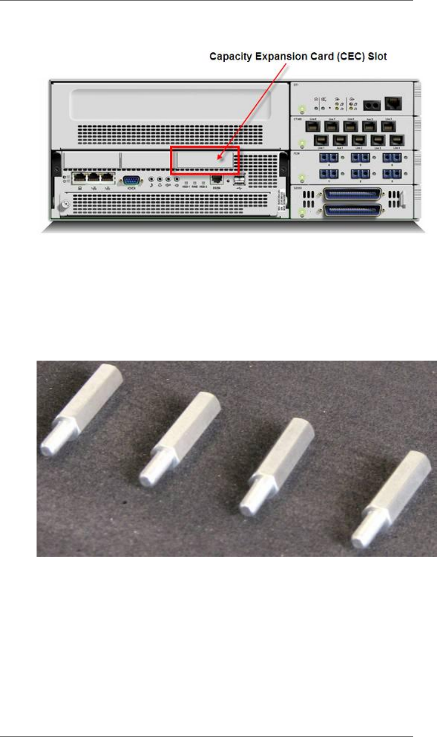
10. There is a plastic cover on the CEC slot of the BCM Main Unit.
11. Remove this cover by applying pressure to the bottom of the faceplate
from the inside of the Base Function tray. Once the cover has come
loose, remove the faceplate.
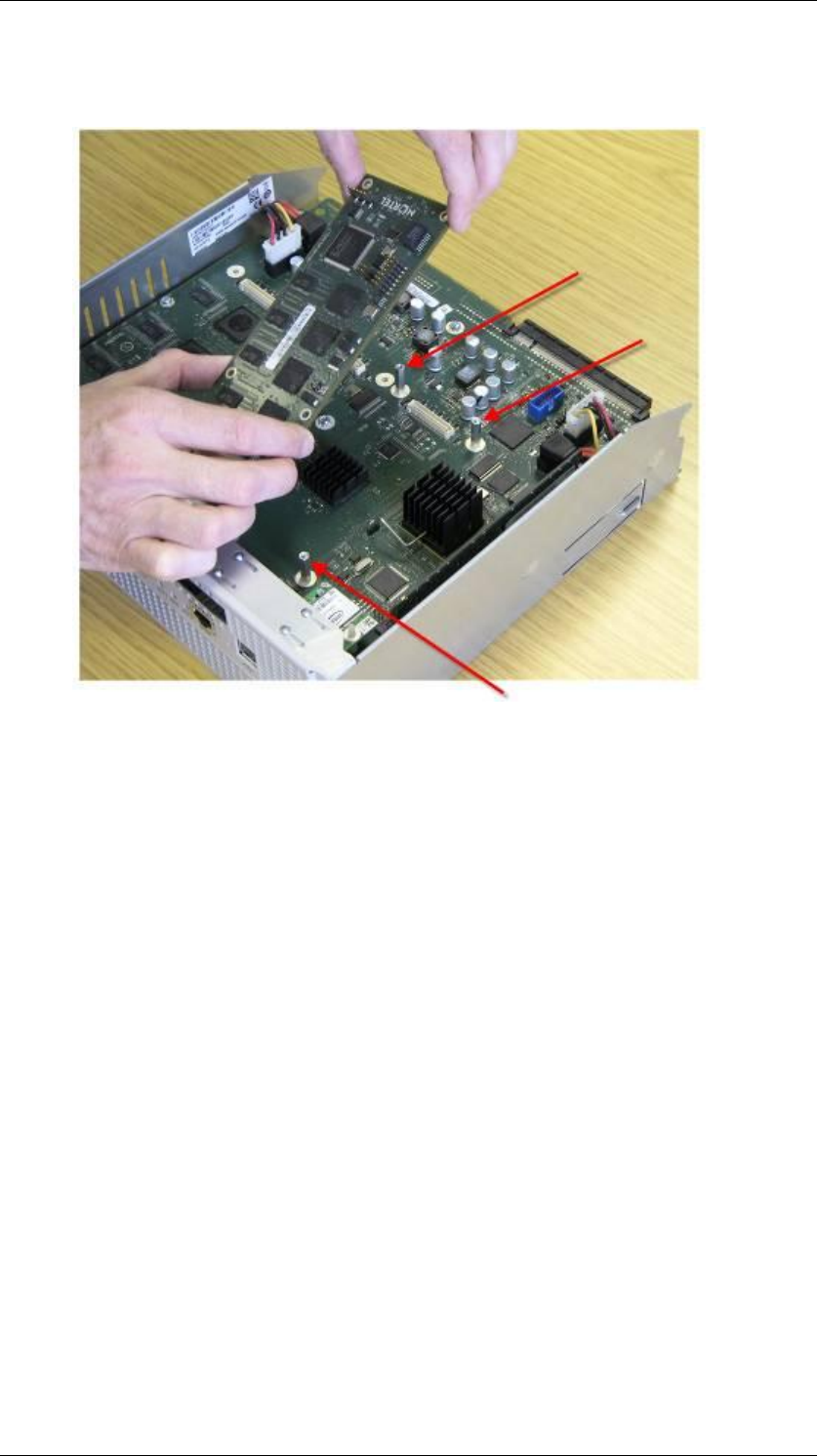
12. The Capacity Expansion Card is connected to the main board by four
metal standoffs (included).
BCM450 Hardware & Installation
NN40011-001 Issue 1.2 BCM450 Rls 6.0 45
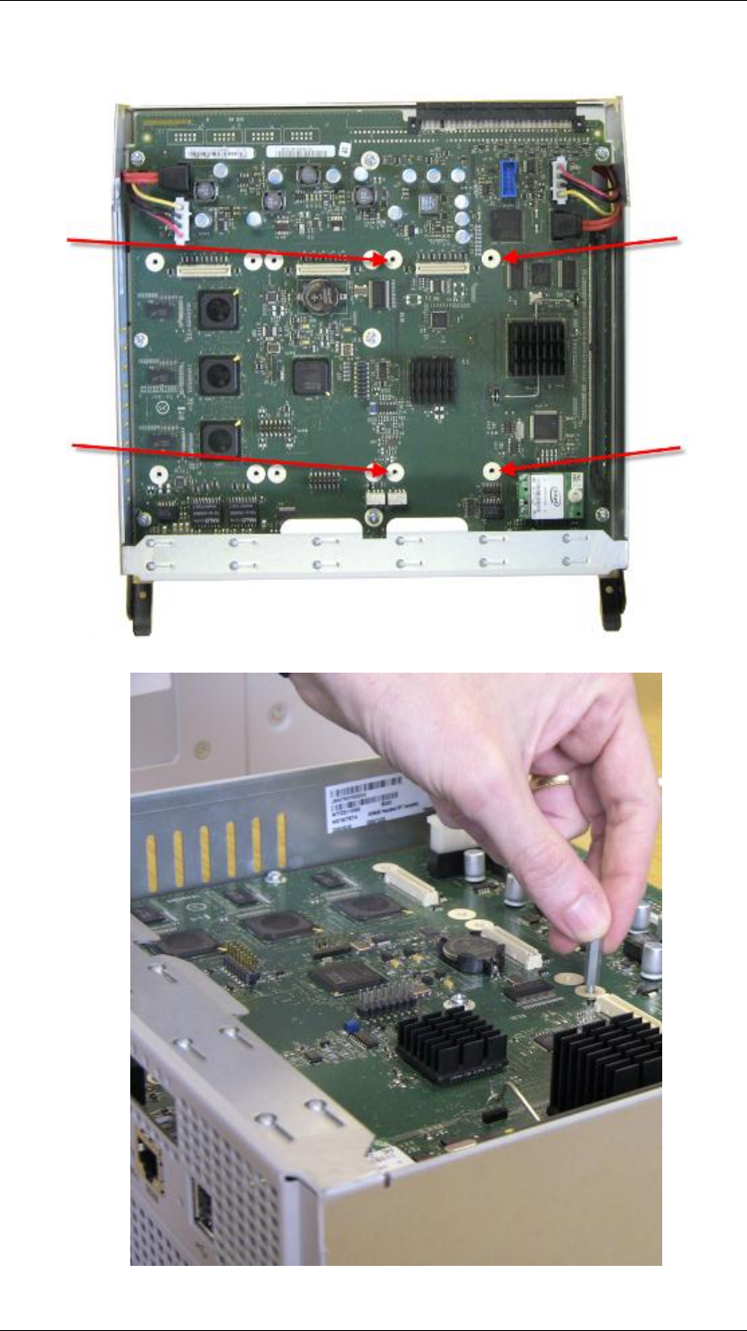
13. Screw the four metal standoffs into the main board of the base function
tray.
BCM450 Hardware & Installation
46 NN40011-001 Issue 1.2 BCM450 Rls 6.0
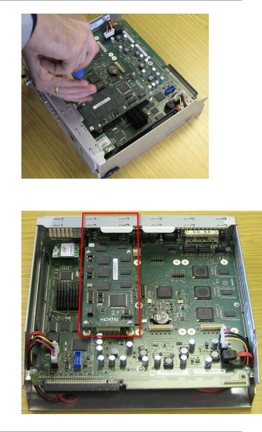
14. Move the CEC into position from the back of the base function tray.
15. Align the connectors on the card and on the main board of the base
function tray and push down. Ensure that the card is connected
securely to the main board.
16. Use the four supplied screws to fasten the card to the standoffs.
BCM450 Hardware & Installation
NN40011-001 Issue 1.2 BCM450 Rls 6.0 47
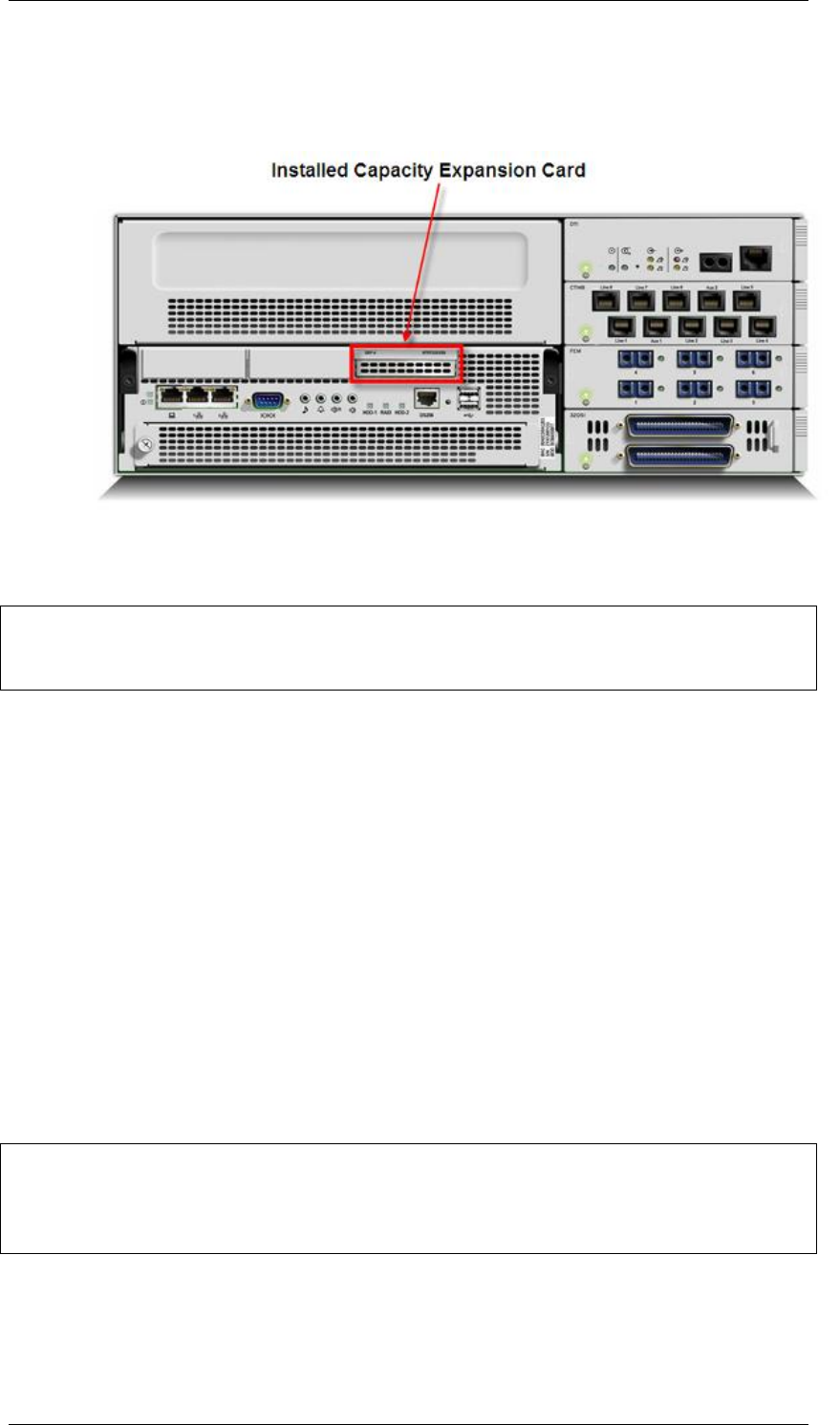
17. The Capacity Expansion Card is now secured to the Base Function
Tray.
BCM450 Hardware & Installation
48 NN40011-001 Issue 1.2 BCM450 Rls 6.0
18. Reinstall the base function tray and power on the BCM450 system.
Please refer to the Installing a Base Function Tray section of this
guide.
Replacing Internal Components
WARNING: Risk of leakage currents
You must disconnect the telephony and data networking cables from the
system before disconnecting the power cord from a grounded outlet.
1. Ensure you have the following tools:
Phillips screwdriver #2, with a 3.5-inch blade
3/16-inch slot screwdriver
Antistatic wrist grounding strap
2. Check for a recent backup of the BCM450 programming. If there is no
recent backup, use Element Manager to back up of all the system data.
3. Use Element Manager to shut down the BCM450 system.
4. Shut down the BCM450
5. Disconnect all cables
6. Disconnect the main unit from the power outlet.
CAUTION: Risk of equipment damage
Protect the hardware components against damage from electrostatic
discharge. Always wear a grounded wrist strap before you handle
components. Always place the components in a static-free container.
7. Remove the BCM450 main unit from the rack, wall, or desktop and set
it on a flat, clean, static-free surface. Access can now be gained to the
BCM‘s internal components.
BCM450 Hardware & Installation
NN40011-001 Issue 1.2 BCM450 Rls 6.0 49
Removing the Base Function Tray (BFT)
The base function tray can be removed from the BCM‘s main chassis to
provide access to the BCM‘s internal components. The BFT can also be
removed and replaced it is defective.
1. Check for a recent backup of the BCM450 programming. If there is no
recent backup, use Element Manager to back up of all the system data.
2. Use Element Manager to shut down the BCM450 system.
3. Disconnect any connectors from the front of the base function tray.
4. Disconnect the BCM system from the AC power outlet.
5. Attach one end of the grounding strap to your wrist and the other end to
a grounded metal surface.
6. Remove the screws from the two BST levers to the front of the BCM.
7. Pull the base function tray levers towards you, the base function tray
should move forward.
BCM450 Hardware & Installation
50 NN40011-001 Issue 1.2 BCM450 Rls 6.0
8. Hold the levers and pull the tray until it is removed from the main unit.
9. Place the tray on a clean, static free surface.
BCM450 Hardware & Installation
NN40011-001 Issue 1.2 BCM450 Rls 6.0 51
Installing a Base Function Tray
A base function tray can be reinstalled after maintenance, or a new base
function tray installed if the original is defective.
1. Check for a recent backup of the BCM450 programming. If there is no
recent backup, use Element Manager to back up of all the system data.
2. Use Element Manager to shut down the BCM450 system.
3. Disconnect the BCM system from the AC power outlet.
4. Attach one end of the grounding strap to your wrist and the other end to
a grounded metal surface.
5. Move the base function tray levers towards you to the unlocked
position.
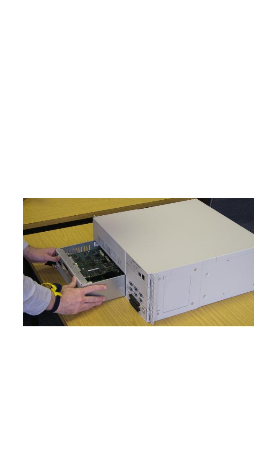
6. Position the base function tray in the main unit bay.
7. Insert the base function tray into the main unit.
BCM450 Hardware & Installation
52 NN40011-001 Issue 1.2 BCM450 Rls 6.0
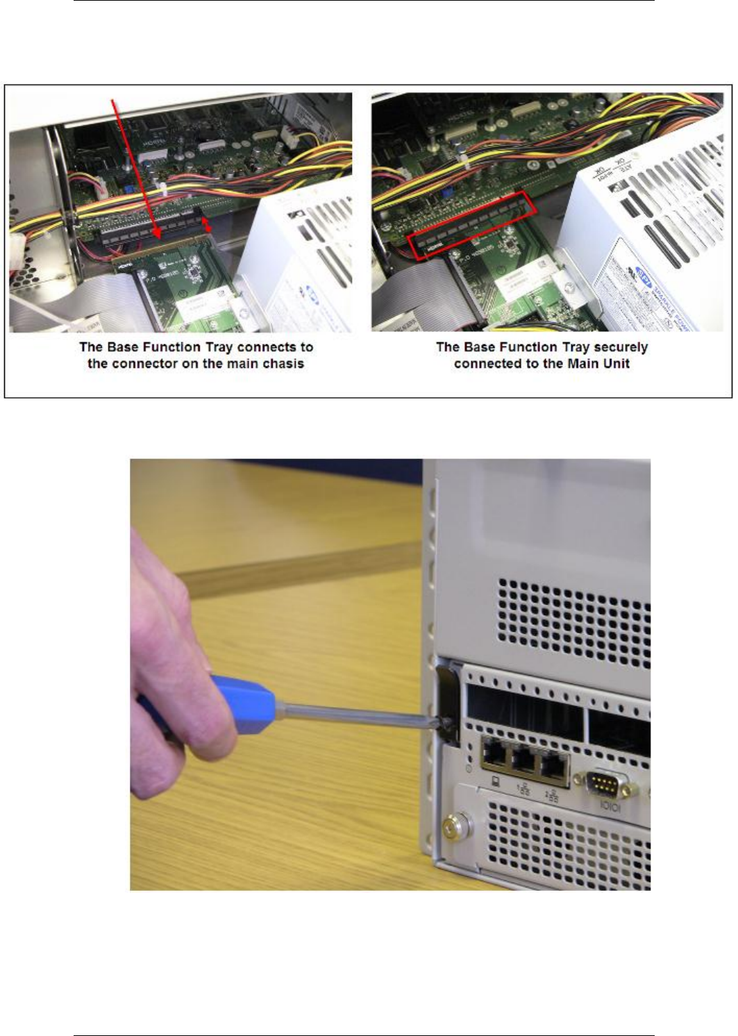
8. Push the base function tray levers forward to the locked position. There
is a connection point
9. Install the base function tray lever screws.
10. Insert all connectors in the correct locations on the base function tray
face.

BCM450 Hardware & Installation
NN40011-001 Issue 1.2 BCM450 Rls 6.0 53
11. Restore the BCM system to operation.
12. Observe the system status monitor LEDs to ensure the base function
tray initializes correctly.
Replacing the Power Supply
Note: Replacing the whole Redundant Power Supply assembly is similar to
the process described in this section. However, if a single Redundant Power
Supply module requires replacing, refer to the Replacing a Redundant
Power Supply Module section of this guide.
1. Check for a recent backup of the BCM450 programming. If there is no
recent backup, use Element Manager to back up all of the system data.
2. Use Element Manager to shut down the BCM450 system.
3. Ensure that all cables are disconnected from the front of the base
function tray.
4. Disconnect the main unit and the expansion cabinet (if applicable) from
the AC power connection.
5. Attach one end of the grounding strap to your wrist and the other end to
a grounded metal surface.
6. Remove the top rear cover panel from the BCM main chassis by
removing the top cover screws to the rear of the main chassis.
BCM450 Hardware & Installation
54 NN40011-001 Issue 1.2 BCM450 Rls 6.0
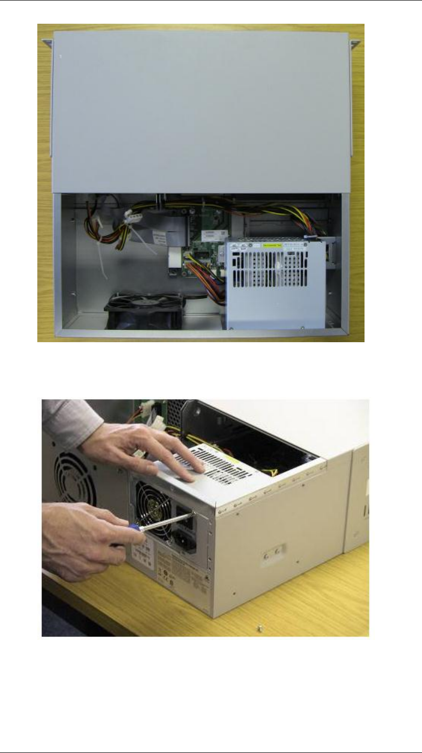
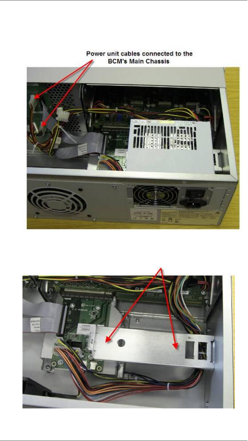
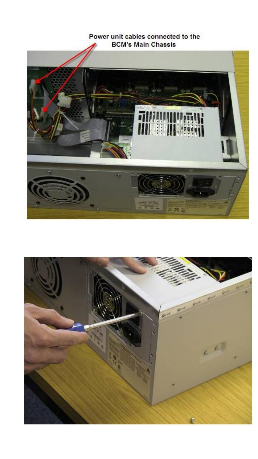
7. The power supply module is located at the back of the unit, on the right
hand side. Loosen the screws securing the power supply module.
BCM450 Hardware & Installation
NN40011-001 Issue 1.2 BCM450 Rls 6.0 55
8. The power unit‘s cables are connected to the main chassis to provide
power to components such as the hard disk and media bay modules.
Disconnect the power unit cables from the main chassis.
9. When disconnected from the main unit, gently lift out the power supply.
10. Place the new power supply onto its holding bracket.
BCM450 Hardware & Installation
56 NN40011-001 Issue 1.2 BCM450 Rls 6.0
11. Reconnect the power supply cables to the BCM‘s main unit.
12. Secure the power supply module by tightening the screws that will hold
it firmly within the BCM chassis.
BCM450 Hardware & Installation
NN40011-001 Issue 1.2 BCM450 Rls 6.0 57
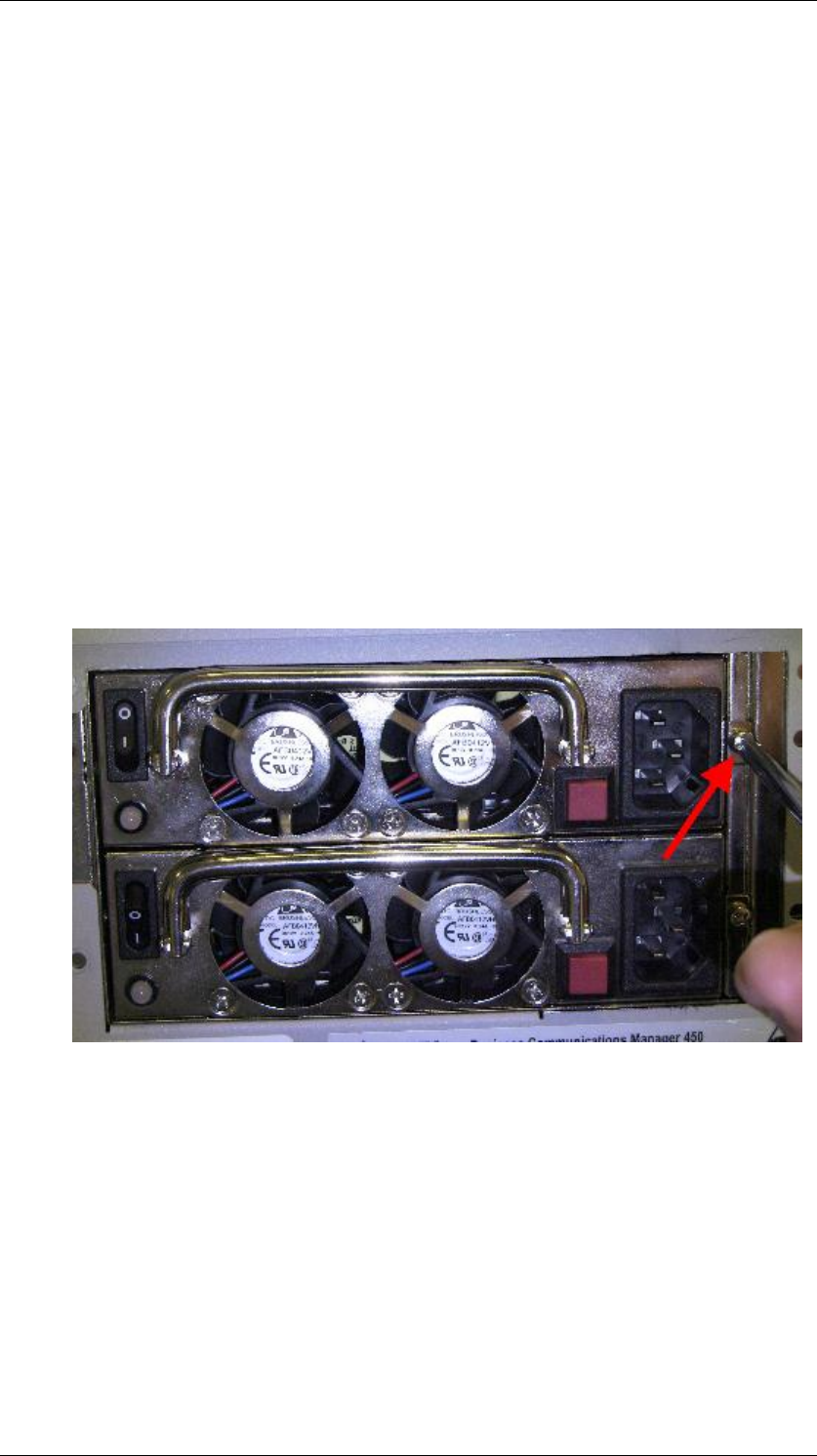
Replacing a Redundant Power Supply Module
Should one of the Redundant Power Supply modules become faulty, it can be
replaced using the following procedure.
1. Check for a recent backup of the BCM450 programming. If there is no
recent backup, use Element Manager to back up all of the system data.
2. Use Element Manager to shut down the BCM450 system.
3. Ensure that all cables are disconnected from the front of the base
function tray.
4. Disconnect the main unit and the expansion cabinet (if applicable) from
the AC power connection.
5. Attach one end of the grounding strap to your wrist and the other end to
a grounded metal surface.
6. Loosen and remove the screw that holds the module in the cage.
BCM450 Hardware & Installation
58 NN40011-001 Issue 1.2 BCM450 Rls 6.0
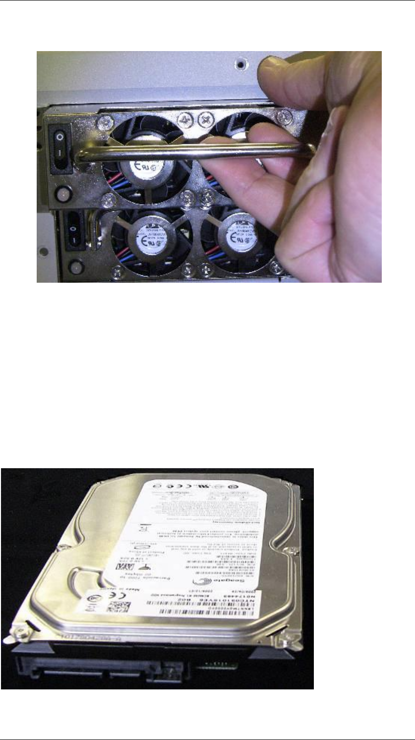
7. Using the handle on the module, pull the module free of the cage.
8. Insert the new module and secure by replacing the screw.
9. Re-attach all the power, telephony and data cables, and power the
system back up again, ensuring that the on / off switch for both
modules is in the on position.
Removing the Hard Disk
The BCM450 is fitted with an 80 GB SATA hard disk. SATA: Serial ATA – A
newer type of hard disk controller allowing faster data transfer than EIDE
controllers. The SATA cable from motherboard to hard drive is significantly
narrower than the IDE cables.
BCM450 Hardware & Installation
NN40011-001 Issue 1.2 BCM450 Rls 6.0 59
If the disk becomes faulty or is damaged, it can be replaced.
Warning: Do not use an electric or magnetic screwdriver to remove the hard
drive or any other internal component. Use of a magnetic screwdriver can
result in the loss of data stored on the disk. The hard disk drive should be
handled with care. If it is knocked or dropped it can be damaged. .
1. Check for a recent backup of the BCM450 programming. If there is no
recent backup, use Element Manager to back up of all the system data
if possible.
2. For RAID enabled systems, i.e. supporting a secondary hard drive, you
can check which hard drive has failed. In the Element Manager
Administration tab, open the System Metrics folder and click on Disk
Mirroring. If either drive is listed as Failed or not listed at all (e.g. the
system may have been rebooted after an earlier failure) that drive will
need replacing.
3. Use Element Manager to shut down the BCM450 system.
4. Disconnect all cables.
5. Disconnect the BCM system from the AC power outlet.
6. Attach one end of a grounding strap to your wrist and the other end to a
grounded metal surface.
BCM450 Hardware & Installation
60 NN40011-001 Issue 1.2 BCM450 Rls 6.0
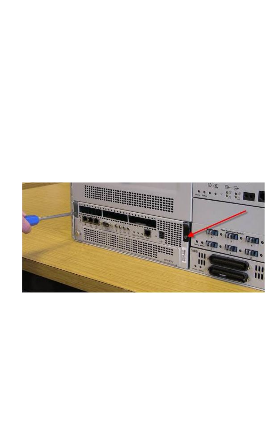
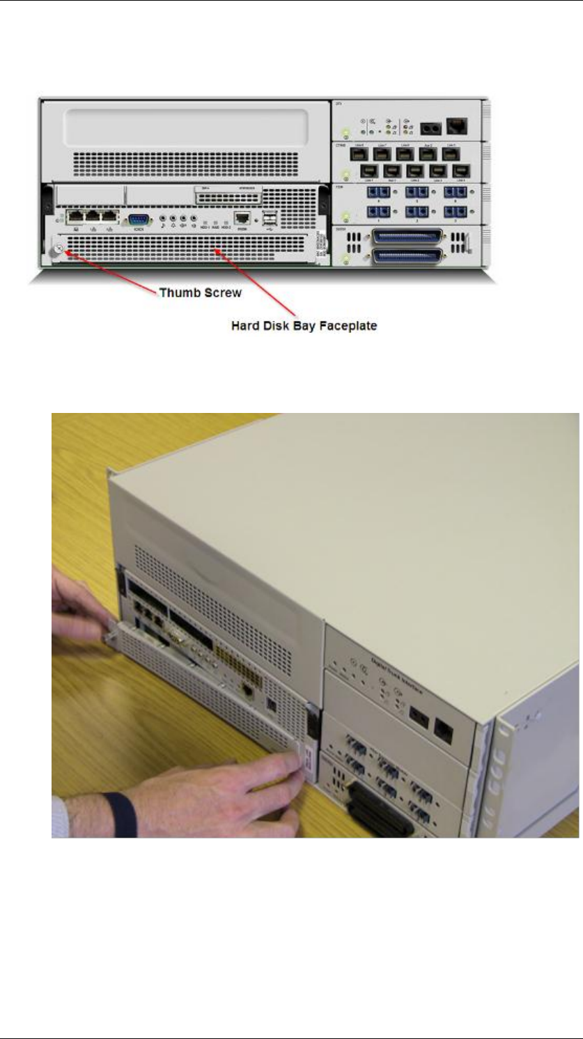
7. On the bottom left of the front panel of the base function tray there is a
thumb screw.
8. Loosen the thumb screw and remove the hard disk bay faceplate.
BCM450 Hardware & Installation
NN40011-001 Issue 1.2 BCM450 Rls 6.0 61
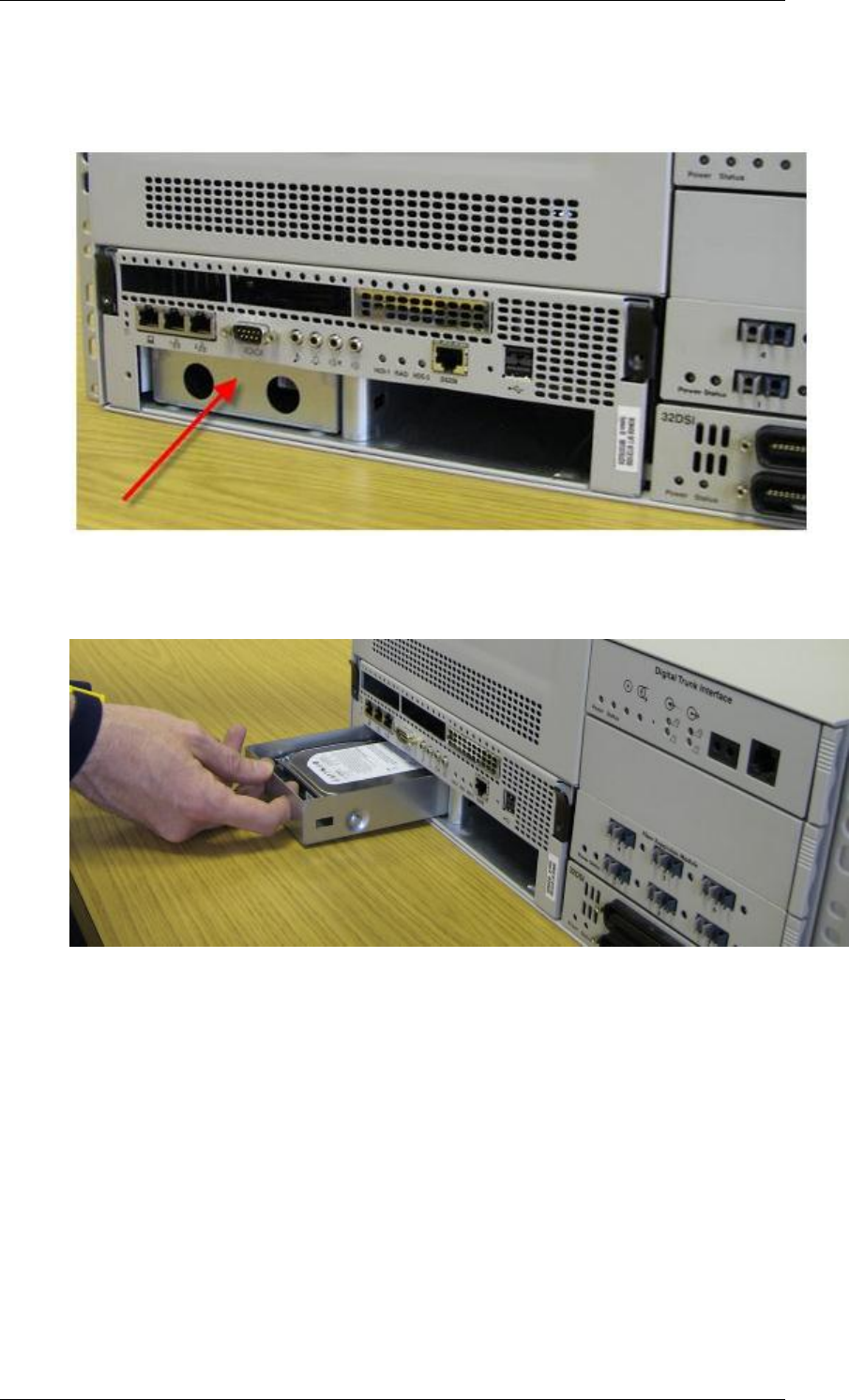
9. The hard disk bracket should be visible. The drive on the left is the
primary hard drive (or HDD-1) and the drive on the right (if present) is
the secondary hard drive (or HDD-2).
10. Pull hard disk and bracket forward, so that it is removed from the
BCM450 main unit.
BCM450 Hardware & Installation
62 NN40011-001 Issue 1.2 BCM450 Rls 6.0
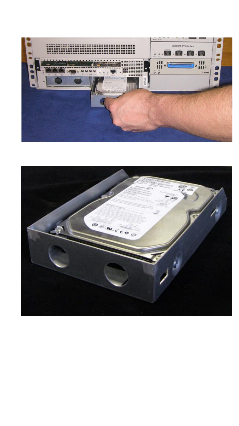
11. If the secondary hard drive (HDD-2) is being replaced, remove the
drive on the right hand side.
12. Place the hard disk and bracket on a flat, clean, static-free surface.
BCM450 Hardware & Installation
NN40011-001 Issue 1.2 BCM450 Rls 6.0 63
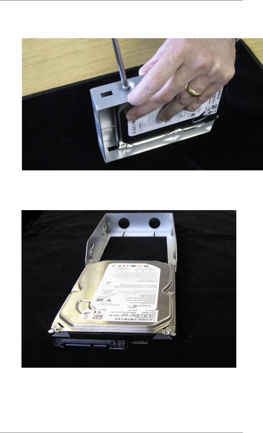
13. Remove the four screws that secure the hard disk to the hard disk
bracket.
14. Remove the hard disk from the hard disk bracket, and place it on a
clean, static free surface.
BCM450 Hardware & Installation
64 NN40011-001 Issue 1.2 BCM450 Rls 6.0
Installing the hard disk
1. Use Element Manager to shut down the BCM450 system, if not already
done so.
2. Disconnect all cables.
3. Disconnect the BCM system from the AC power outlet.
4. Attach one end of a grounding strap to your wrist and the other end to a
grounded metal surface.
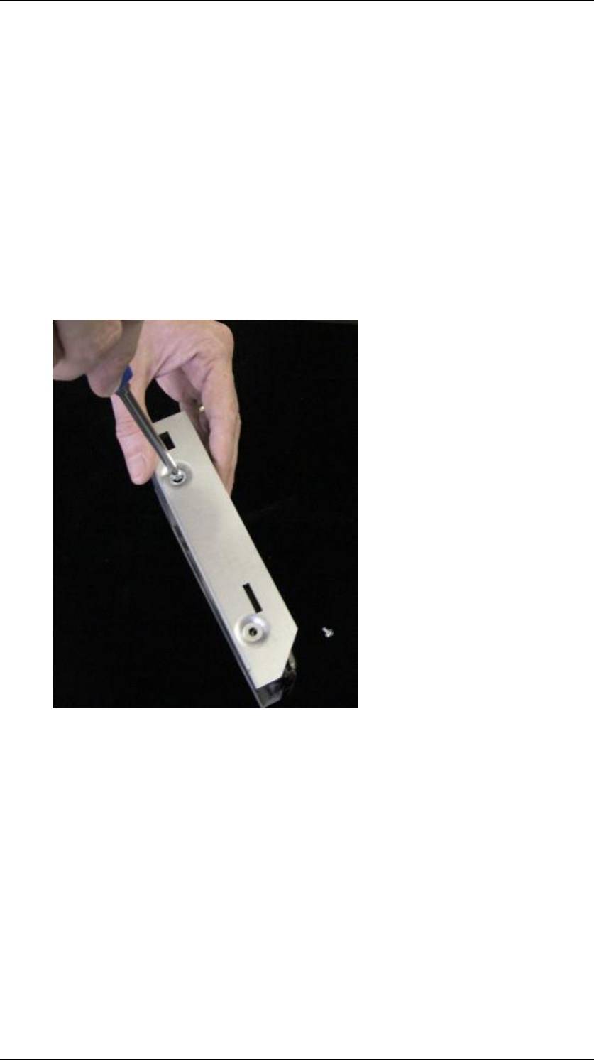
5. Place the new hard disk in the hard disk bracket and use the four hard
disk bracket screws to secure the hard disk to the bracket.
BCM450 Hardware & Installation
NN40011-001 Issue 1.2 BCM450 Rls 6.0 65
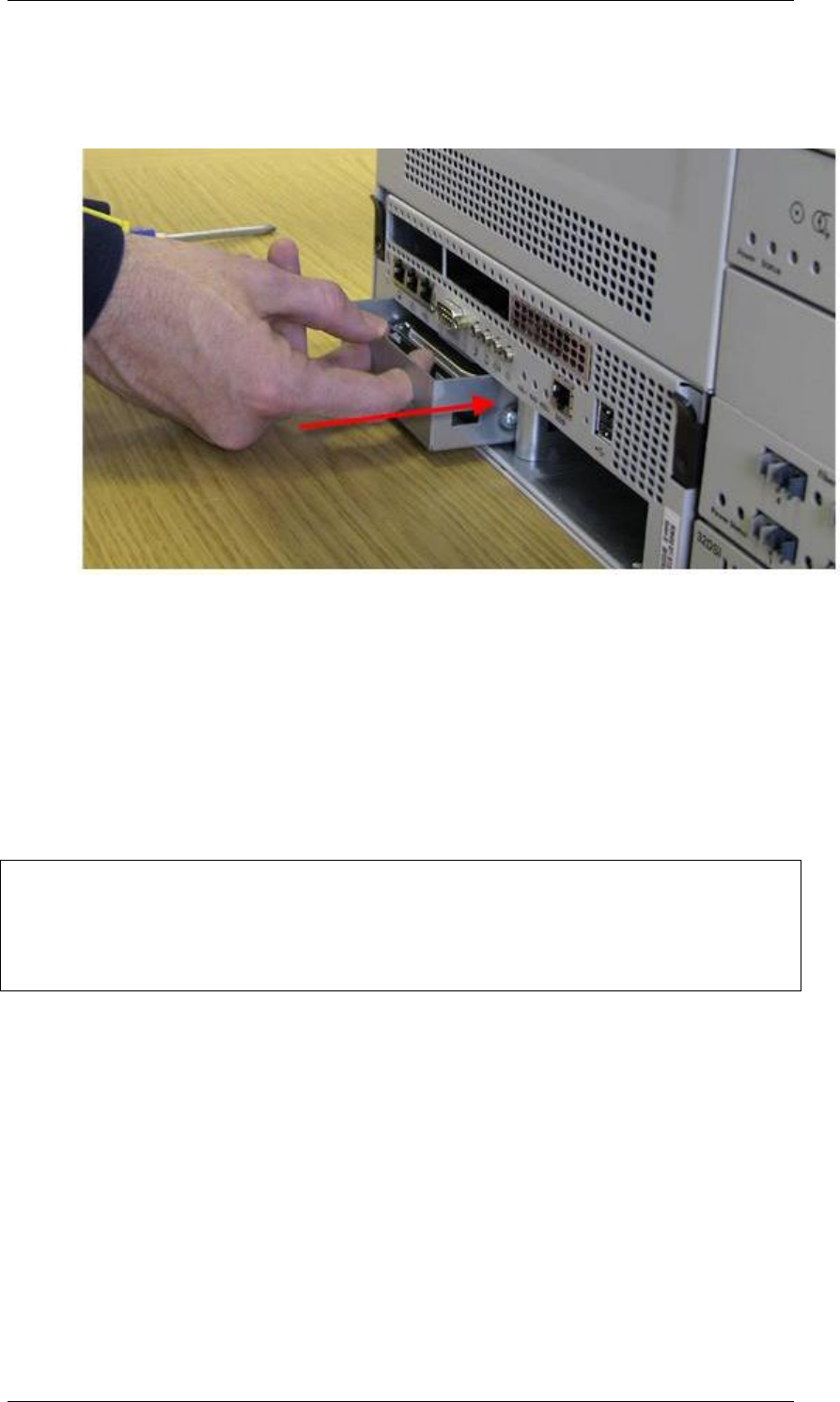
6. Push the hard disk and bracket forward into the primary hard disk bay
(the left hand slot) if replacing the primary hard drive, or the secondary
hard disk bay (the right hand slot) if replacing the secondary hard drive.
7. Ensure that the hard disk bracket is seated properly.
8. Reattach the hard disk front cover panel to the main unit of the BCM.
9. Tighten the thumb screw.
10. If you have just installed a Multi-Image hard drive in a non-RAID (i.e.
single hard drive) system, please now proceed with the Preparing the
Multi-Image Hard Drive section.
Note: For RAID systems only. If you have just replaced one of the drives with
a Multi-Image hard drive, the active RAID drive will overwrite the Multi-Image
drive. If both RAID drives have failed and have been replaced by the Multi-
Image Hard Drive, proceed with the Preparing the Multi-Image Hard Drive
section.
11. If required, perform a restore or manually reprogram the system as per
the System Start Up process (refer to the relevant System Start Up
Guide).
12. For RAID systems, check that the RAID service is enabled in Element
Manager. In the Administration tab, navigate to System Metrics,
Disk Mirroring. If the Admin Status field reads Disabled, click the
Change button to change the status. This will automatically reboot the
BCM.

BCM450 Hardware & Installation
66 NN40011-001 Issue 1.2 BCM450 Rls 6.0
Preparing the Multi-Image Hard Drive
The Multi-Image Hard Drive field Replaceable Unit contains multiple BCM
software images. This allows for a common hard drive FRU to be installed in
either a BCM50 or BCM450 chassis, and offers a range of software releases
to be applied to the BCM having the hard drive replaced.
Once installed, the preparation process involves powering up the BCM,
connecting to the BCM via a SSH client such as PuTTY to access the
command menu, and selecting the correct software version for the BCM. On
process completion, all non-required images will have been erased, and the
BCM will boot up ready for a restore of a previous backup, or manual re-
programming via the System Start Up process (refer to the System Start Up
Guide).
Note: For RAID systems this procedure is only required if both RAID drives
have failed. Installing a single Multi-Image Hard drive in a functioning RAID
system will result in the Multi-Image Hard Drive being overwritten by the active
RAID drive.
Note: Perform the preparation process from a PC connected to the OAM port
of the BCM.
Use the following procedure to select the required software release of the
Multi-Image hard drive.
1. Once the hard drive is correctly installed, as described in the
Removing the Hard Disk and Installing the Hard Disk sections of
this guide, connect a PC to the OAM port of the BCM and power up the
BCM. If you experience problems in connecting to the BCM when
configured to obtain an IP address automatically via DHCP, configure
your PC with the following IP settings:
IP Address = 10.10.11.2
Subnet Mask = 255.255.255.252
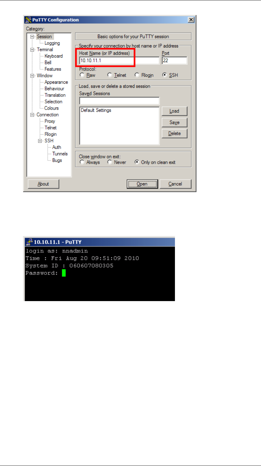
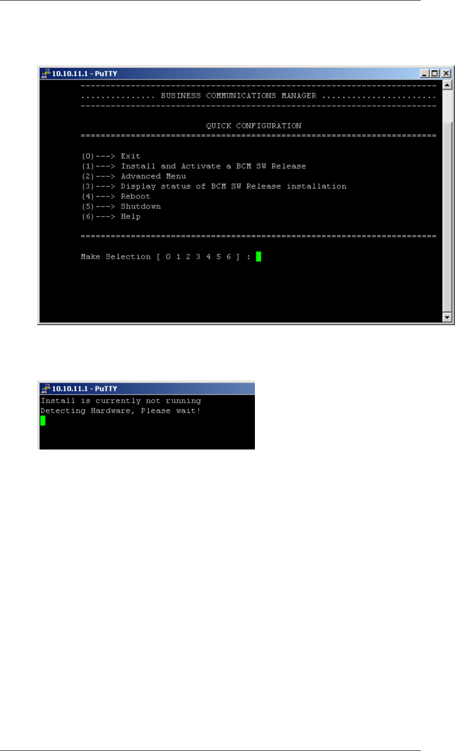
2. When the BCM is ready to accept a SSH client connection, the Power
LED will be full green, and the Status LED will be blinking orange.
Open up a SSH client such as PuTTY, and connect to the default OAM
port address 10.10.11.1
BCM450 Hardware & Installation
NN40011-001 Issue 1.2 BCM450 Rls 6.0 67
3. Login to the BCM using the default details:
User = nnadmin
Password = PlsChgMe!
BCM450 Hardware & Installation
68 NN40011-001 Issue 1.2 BCM450 Rls 6.0
4. The Quick Configuration menu will display. Select 1 -> Install and
Activate a BCM SW Release.
5. Detection of the BCM hardware type - i.e. BCM50 or BCM450 (BCM
200/400 5.0 or later systems will be detected as BCM450) – will begin.
BCM450 Hardware & Installation
NN40011-001 Issue 1.2 BCM450 Rls 6.0 69
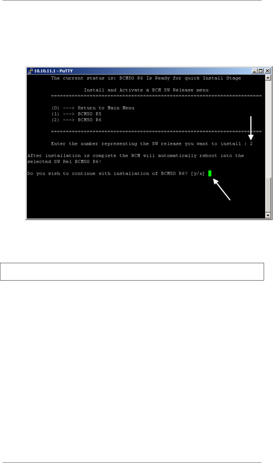
6. When the hardware type has been detected, you will be presented with
the option of applicable software releases to apply to the hard drive.
Enter the required software release. (The options shown below are for
a BCM50 system. The relevant BCM450 options will be shown if a
BCM450 system is detected.)
7. If you have made an incorrect selection, enter n at the Do you wish to
continue… prompt (this will return you to the main menu). Otherwise,
enter y to confirm and continue.
Note: If the wrong software release is selected and confirmed, a new
replacement hard drive will be required as the following process is irreversible.
BCM450 Hardware & Installation
70 NN40011-001 Issue 1.2 BCM450 Rls 6.0
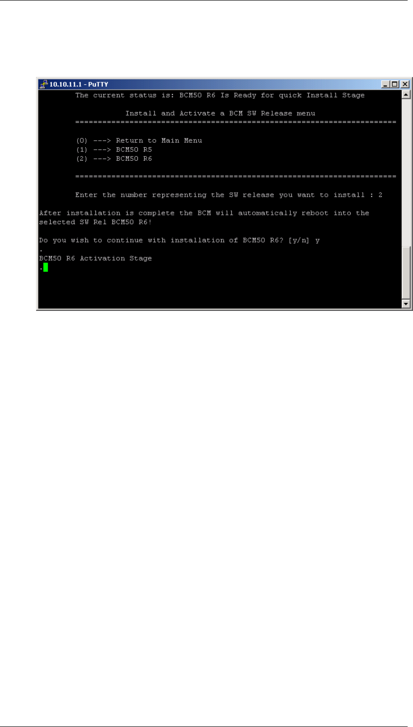
8. The selected software release will be applied to the hard drive, and
could take up to 25 mins to complete. The SSH client will be
disconnected from the BCM.
9. Once the process is complete, the BCM will boot up into a normal
working state (both the Power and Status LED‘s should be green).
Either perform a restore or manually reprogram the BCM via the
System Start Up process (refer to the relevant System Start Up
Guide).

BCM450 Hardware & Installation
NN40011-001 Issue 1.2 BCM450 Rls 6.0 71
Replacing the Random Access Memory (RAM) Card
The RAM card can be replaced if it is damaged or defective. The card
required is a DDR RAM Card (up to 1 gigabyte, 533 megahertz.
1. Check for a recent backup of the BCM450 programming. If there is no
recent backup, use Element Manager to back up of all the system data.
2. Use Element Manager to shut down the BCM450 system.
3. Disconnect all cables
4. Disconnect the BCM system from the AC power outlet.
5. Attach one end of the grounding strap to your wrist and the other end to
a grounded metal surface.
6. Remove the base function tray.
BCM450 Hardware & Installation
72 NN40011-001 Issue 1.2 BCM450 Rls 6.0
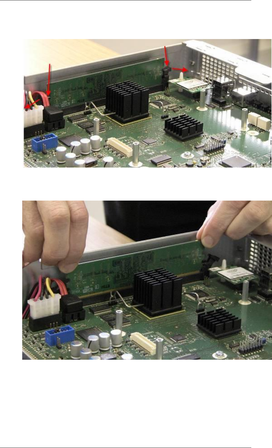
7. Carefully push down on the holding clips positioned on either side of
the DIMM.
8. When you press down on the holding clips, the DIMM should lift out of
the DIMM slot.
9. Place the DIMM in a static-free container.
10. Position and correctly align the new DIMM (edge connectors first) into
the connector.
BCM450 Hardware & Installation
NN40011-001 Issue 1.2 BCM450 Rls 6.0 73
11. Carefully and firmly press down on the top of the DIMM card with your
thumbs. At the same time, use your index fingers to move the fastening
tabs inward toward the card.
12. When the card is completely inserted in the connector, the holding clips
should clip to the side of the DIMM card.
13. Reinstall the base function tray.
14. Insert all connectors in the correct locations on the base function tray
face.
15. Restore the BCM system to full operation as required.
Replacing a Cooling Fan
Note: For BCM‘s fitted with a Redundant Fan, determine which fan has failed
before removing the case. The procedure described in this section can be
applied to either fan.
To replace a defective cooling plan:
1. Use Element Manager to shut down the BCM450 system.
2. Disconnect all cables.
3. Disconnect the BCM system from the AC power outlet.
4. Attach one end of the grounding strap to your wrist and the other end to
a grounded metal surface.
BCM450 Hardware & Installation
74 NN40011-001 Issue 1.2 BCM450 Rls 6.0
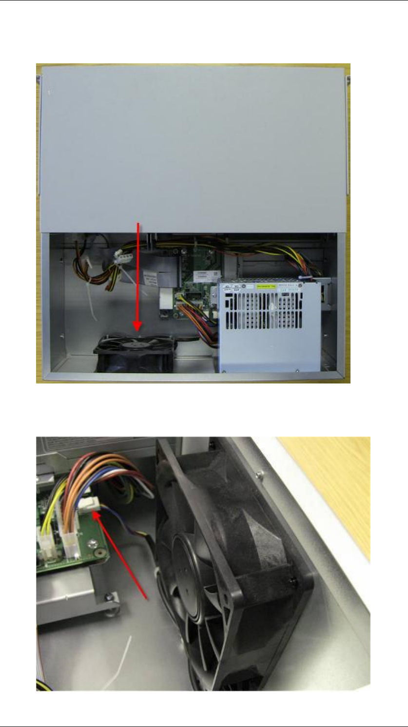
5. The fan can be accessed by removing the panel cover located to the
rear of the BCM‘s main unit.
6. Disconnect the fan cable connector from the connector connected to
the BCM main unit.
BCM450 Hardware & Installation
NN40011-001 Issue 1.2 BCM450 Rls 6.0 75
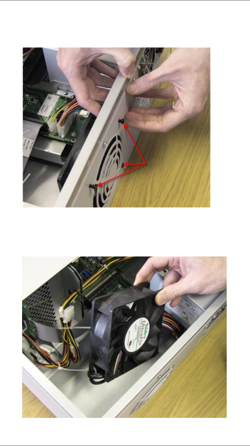
7. Remove the fan‘s retention clips. This can be achieved by pushing the
clip out from the inside of the chassis. The retention clips have two
parts: a center pin and a collar.
8. Remove the center pin and collar from the BCM and place them in a
safe location.
9. Lift the fan away from the BCM unit.
BCM450 Hardware & Installation
76 NN40011-001 Issue 1.2 BCM450 Rls 6.0
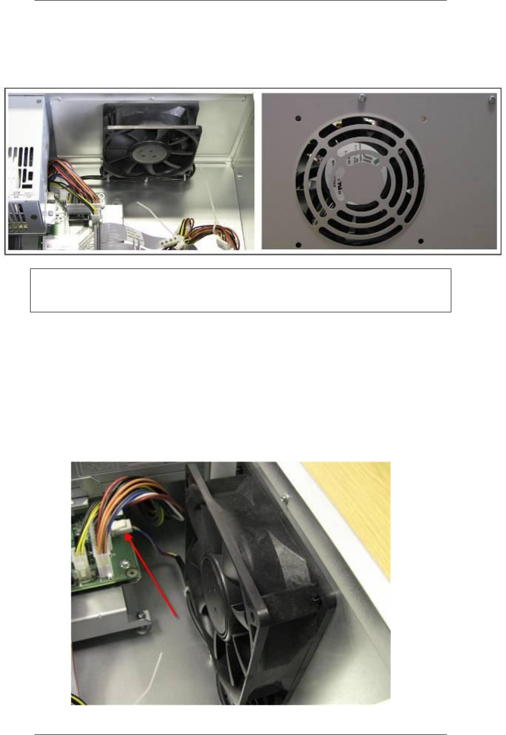
10. Place the new fan in the BCM unit in the same position as the old fan.
11. Ensure the fan cable is oriented to the bottom of the fan and that the
fan label is closest to the grill on the panel.
Note: You must ensure the label of the new fan faces the back of the
BCM450 unit as air must flow out of the unit as indicated by the embossed
arrows on the fan itself.
12. Align the fan chassis mounting holes with the holes in the fan access
panel.
13. Hold the fan in place against the BCM chassis and push the retention
clip collars through mounting holes.
14. Insert the center pin into the retention clip collar.
15. Connect the fan cable connector to the base function tray connector.
BCM450 Hardware & Installation
NN40011-001 Issue 1.2 BCM450 Rls 6.0 77
16. Ensure that the fan is securely connected to the BCM chassis.
17. Restore the BCM450 system to operation as required.
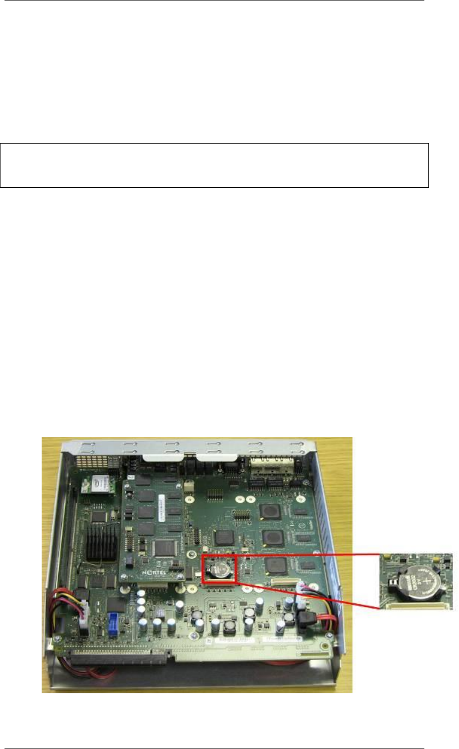
Replacing the Clock Battery
The clock battery can be replaced if it fails. This clock battery supplies the
power required to keep accurate CMOS information if there is a power failure.
Note: You must replace the battery with a CR2032, 3 Volt Maxell coin cell
battery. The use of any other manufacturer can invalidate the safety approval
of the BCM450 main unit and possibly cause a fire or explosion.
1. Check for a recent backup of the BCM450 programming. If there is no
recent backup, use Element Manager to back up of all the system data.
2. Use Element Manager to shut down the BCM450 system.
3. Disconnect all cables.
4. Disconnect the BCM system from the AC power outlet.
5. Attach one end of the grounding strap to your wrist and the other end to
a grounded metal surface.
6. Remove the Base Function Tray.
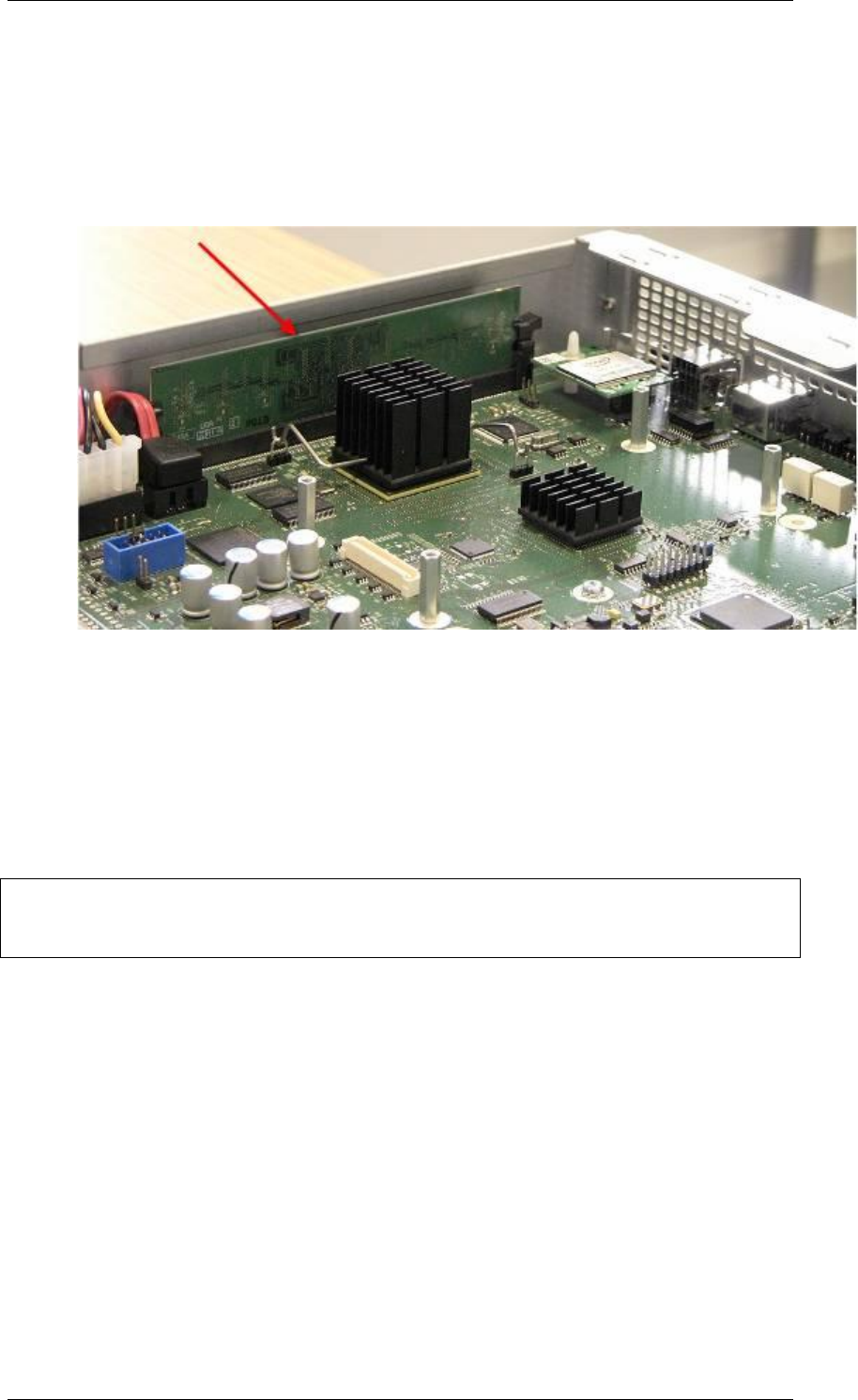
7. The clock battery is positioned towards the center of the main board of
the base function tray.
BCM450 Hardware & Installation
78 NN40011-001 Issue 1.2 BCM450 Rls 6.0
8. Carefully lift the battery out of its socket. Do not use any type of tool to
remove the battery.
9. Carefully align the new battery with the top of the battery socket.
10. The positive side of the battery must face upwards.
11. Gently push down until the battery snaps into the socket.
12. Reinstall the base function tray.
13. Restore the BCM system to operation.
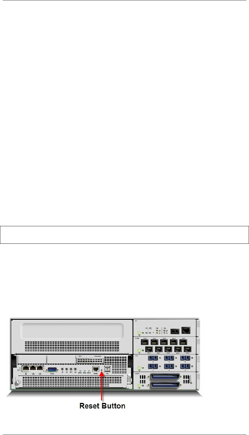
Resetting the BCM450 using the Reset Button
The BCM450 can be reset by pushing the reset button situated at the front of
the BCM450. The length of time that the button is pressed determines the
type of reset that is performed.
If the reset button is pressed for less then 5 seconds, the BCM will
begin the reboot process which will complete in less then 30 seconds.
If the BCM450 Reset Button is held for 5 seconds, the BCM450 will
immediately reboot. Data loss may occur.
Note: The immediate reboot option should only be utilized when the BCM450
is not responding to normal reboot operations or is entirely non-responsive.
If the BCM450 system has been shut down from the CLI, the Reset
Button must be held for 5 seconds to initiate the reboot process.
Upon restart caused by a press of the Reset Button, the BCM450 will
wait up to 10 seconds for a user to login to the BCM Maintenance CLI.
If no user logs in to the Maintenance CLI within this 10 second period,
the BCM will boot the BCM‘s operating system.

BCM450 Hardware & Installation
NN40011-001 Issue 1.2 BCM450 Rls 6.0 79
When the BCM450 is in the reset condition, further modifications can be made
via the Maintenance CLI that can be accessed by the Serial Port of the BCM.
BCM Command Line Interface
The BCM Command Line Interface (CLI) provides configuration information
and reset utilities and is dependent on which state the BCM is in:
Configuration CLI
Maintenance CLI
Configuration CLI
The Configuration CLI can be accessed during normal operation and provides
the following options:
0 - Exit. The system exits the CLI to the login prompt.
1 - Reboot. The system reboots to the Main OS.
2 - Shutdown. The system shuts down. You need physical access to the
BCM450 hardware to restart the system.
3 - Safe OS. The system reboots to the Safe OS and waits 1 minute for you to
login. When you login within 1 minute, the Maintenance CLI displays. If you do
not login within 1 minute, the system changes to the Main OS.
4 - Configuration Reset. A Level 1 reset occurs. The system resets all
configuration data to the factory defaults.
5 - Software Reset. A Level 2 reset occurs. The system resets all
configuration data and software to the factory defaults.
6 - IP Configuration. You can configure the following basic IP settings:
0 - Return to Previous Menu. The system returns to the main menu.
1 - Hostname. The hostname of the system.
2 - IP Address. The IP address of the system.
3 - Subnet Mask. The subnet mask for the IP address.
4 - Default Gateway. The default gateway for the system.
5 - DHCP Client Mode. Enable or disable the DHCP client.
6 - Commit Changes. Save changes to the IP settings.
7 - Reload Settings. Reload the existing IP settings.
7 – Health Check. This option checks:
The BCM chassis type to determine whether the BCM is a
standard system, an upgraded system, or out-of-factory
redundant system.
RAID keycode to determine whether RAID feature is
provisioned on the BCM (RAID is always provisioned on an out-
of-factory redundant system).
Installation of secondary hard drive in a BCM in which RAID
feature is provisioned.
Type of power supply (redundant or standard) installed on the
system (Out-of-factory redundant system always have a
redundant power supply installed)

BCM450 Hardware & Installation
80 NN40011-001 Issue 1.2 BCM450 Rls 6.0
Status of the power supply module(s), power supply fan(s), and
chassis fan(s)
Maintenance CLI
The Maintenance CLI displays when the system is in the Safe OS mode. The
Safe OS is a diagnostics mode that can be used if the Main OS is
experiencing problems. No applications or telephony services are running
when the BCM is in Safe OS mode.
Note: It is recommended that you access the Maintenance CLI only under the
advice of support personnel.
The Maintenance CLI can be accessed from option 3 of the Configuration CLI
(select option 3 and attempt to access the CLI within 1 minute). The following
options can then be used:
0 - Exit. The system exits to the Safe OS login prompt.
1 - Reboot into Main OS. The system reboots to the Main OS.
2 - Shutdown. The system shuts down. You need physical access to the
BCM450 hardware to restart the system.
3 - Reboot into Safe OS. The system reboots to the Safe OS and waits 1
minute for you to login. If you do not login within 1 minute, the system
changes to the Main OS.
4 - Transition to Main OS. The system changes from the Safe OS to the
Main OS without restarting.
5 - Configuration Reset. A Level 1 reset occurs. The system resets all
configuration data to the factory defaults.
6 - Software Reset. A Level 2 reset occurs. The system resets all
configuration data and software to the factory defaults.
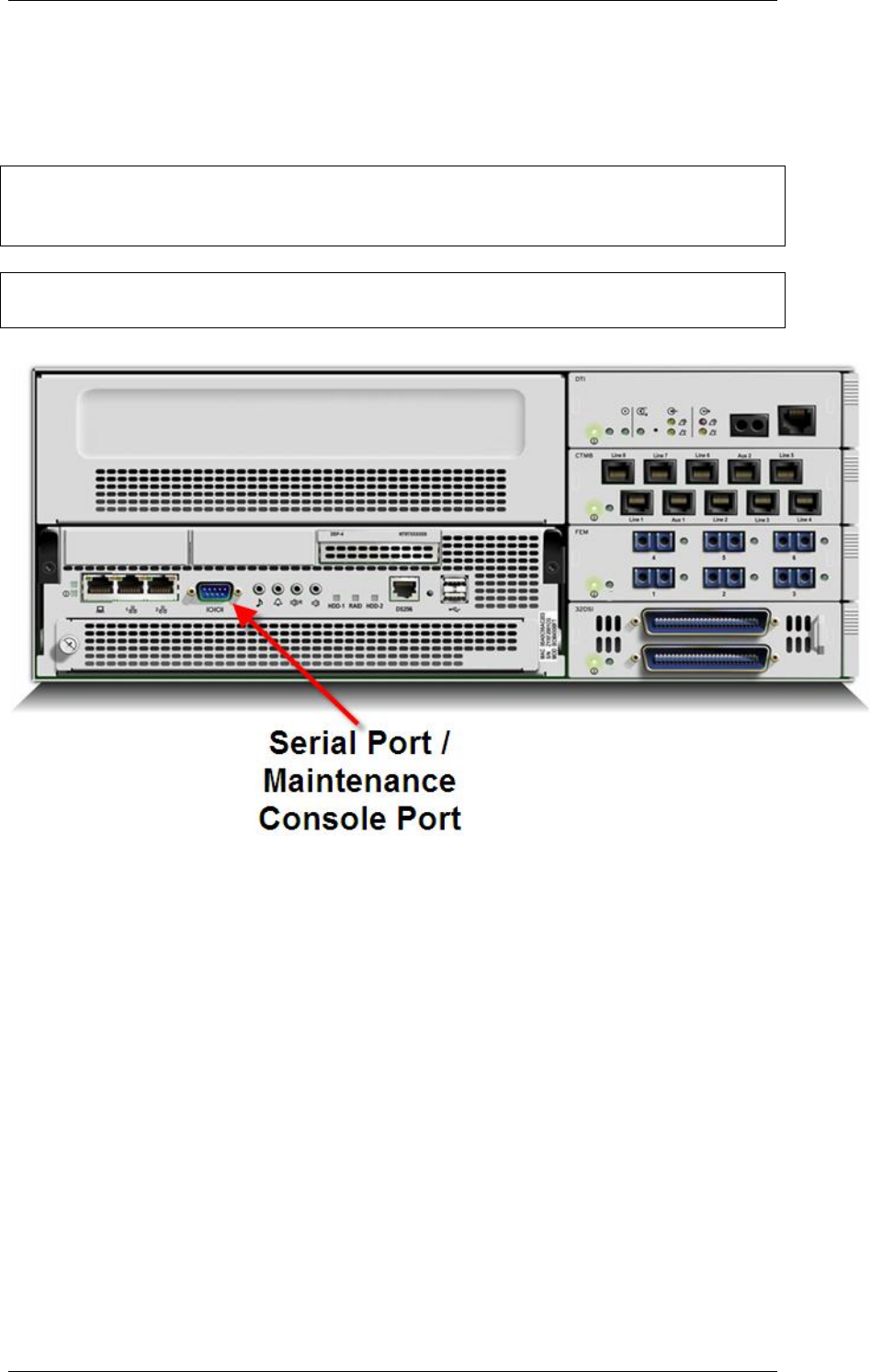
BCM450 Hardware & Installation
NN40011-001 Issue 1.2 BCM450 Rls 6.0 81
Accessing the BCM’s Command Line Interface via the Serial
Port
The Serial Port of the BCM450 is located on the front panel.
Note: The CLI method of accessing the BCM is intended for experienced
technicians, or as directed by Avaya Technical Support. Improper use of the
CLI may result in data loss.
Note: To use this method of accessing the BCM your PC must have a serial
port. You will also require a 9-pin female connector serial cable.
1. Connect the serial cable to the serial port of the pc and to the serial
port of the BCM
2. Open a terminal emulation program such HyperTerminal (Start,
Programs, Accessories, Communications, HyperTerminal if using the
Windows™ Classic Menu).
3. HyperTerminal prompts for a name for this connection. Enter a
suitable name and click OK.
4. Select the COM port you are connected to the BCM by, and click on
OK.
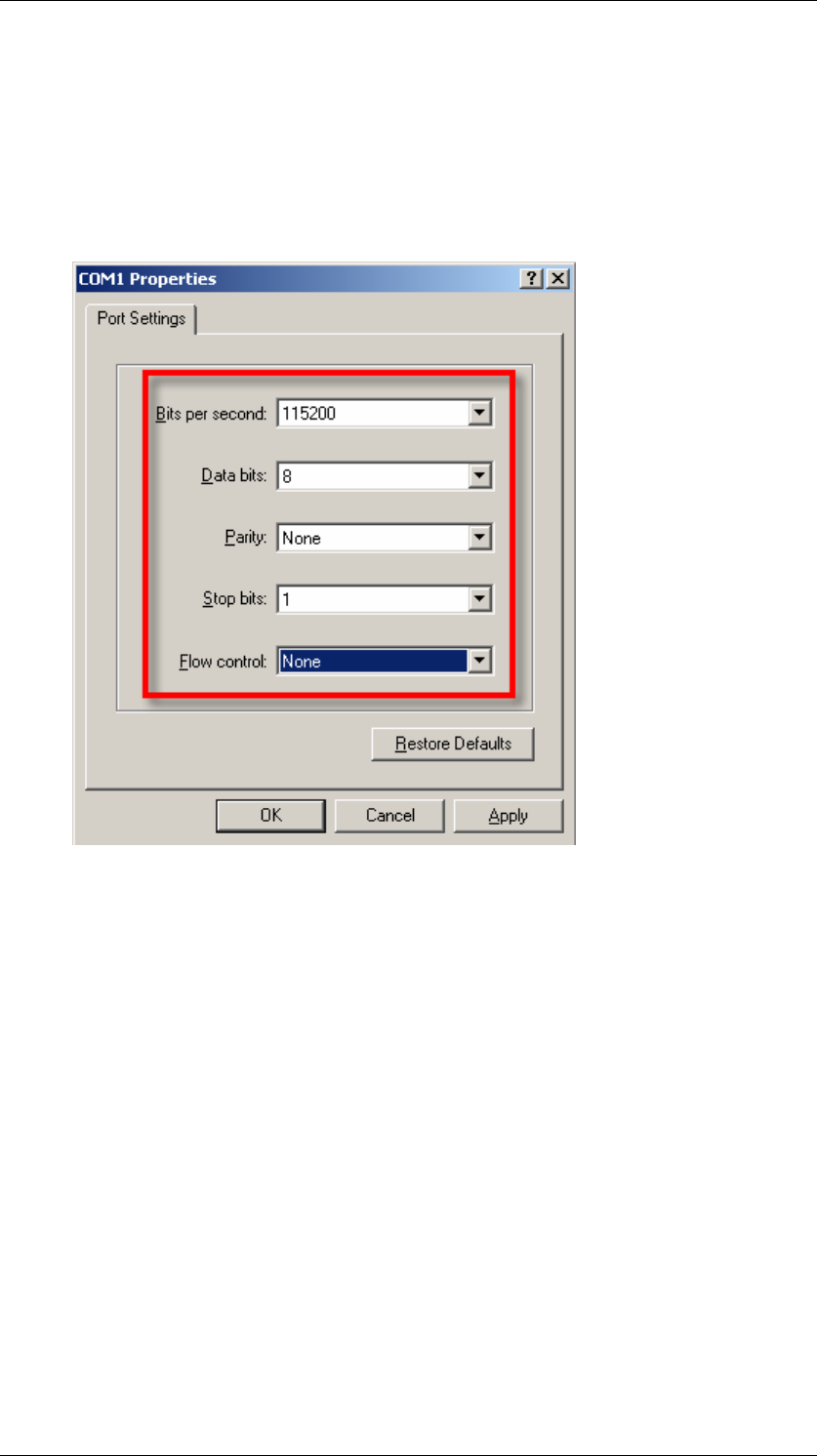
BCM450 Hardware & Installation
82 NN40011-001 Issue 1.2 BCM450 Rls 6.0
5. Configure the following settings, and click OK:
o Bits per second: 115200
o Data Bits: 8
o Parity: None
o Stop Bits: 1
o Flow Control: None
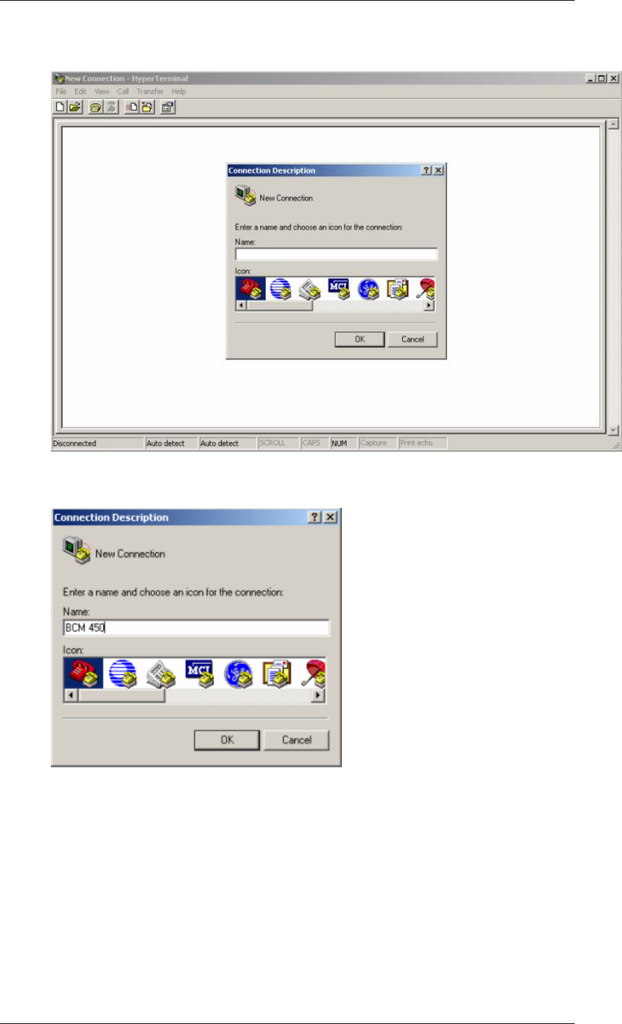
BCM450 Hardware & Installation
NN40011-001 Issue 1.2 BCM450 Rls 6.0 83
6. You will be presented with a Hyper Terminal window.
7. Enter a name for this connection in the Name field and click OK.
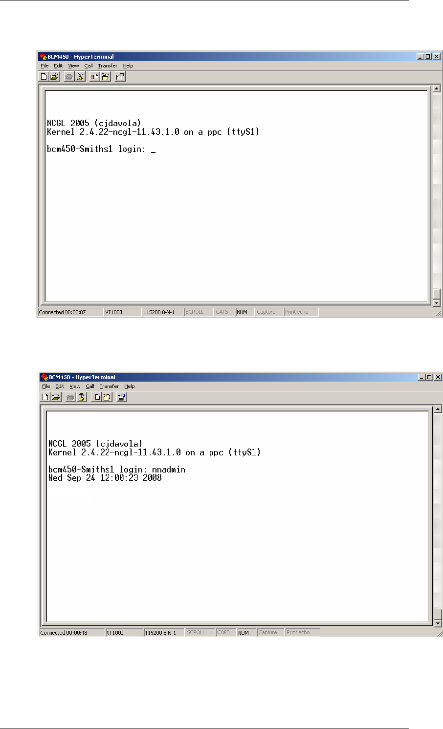
BCM450 Hardware & Installation
84 NN40011-001 Issue 1.2 BCM450 Rls 6.0
8. Press the enter key. You will be presented with a login screen.
9. Enter the login credentials; enter the username nnadmin (press the
Enter key)
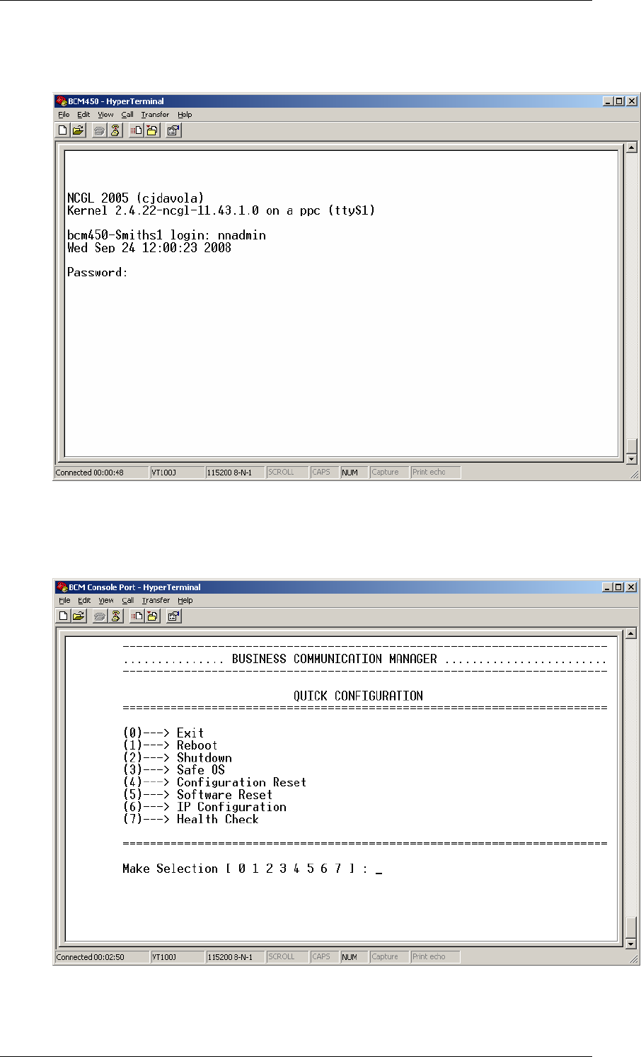
BCM450 Hardware & Installation
NN40011-001 Issue 1.2 BCM450 Rls 6.0 85
10. Then enter the password PlsChgMe! or whatever the password has
been changed to (press the Enter key).
11. You will then be presented with the CLI. Make your selections as
described in the Configuration CLI or Maintenance CLI sections of
this guide.
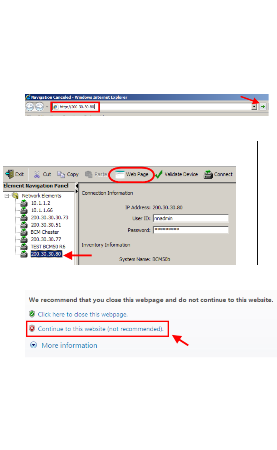
BCM450 Hardware & Installation
86 NN40011-001 Issue 1.2 BCM450 Rls 6.0
Accessing the Command Line Interface Using PuTTY
PuTTY is a software tool that can be used to access the BCM CLI, and can be
downloaded from the Administrator Applications web page.
Use the following procedure to install PuTTY and connect to the BCM CLI.
1. Open Internet Explorer.In the address field type (replacing the relevant
part with your BCM IP address): http://<bcm ip address>/
2. Click on Go, or press Return on your keyboard.
Note: You can also use the Web Page button in Element Manager to launch a
web broswer session. The BCM you wish to access must be selected in the
Element Navigation Panel to do this.
3. If you are presented with the Certificate Error window, click on
Continue to this website (not recommended).
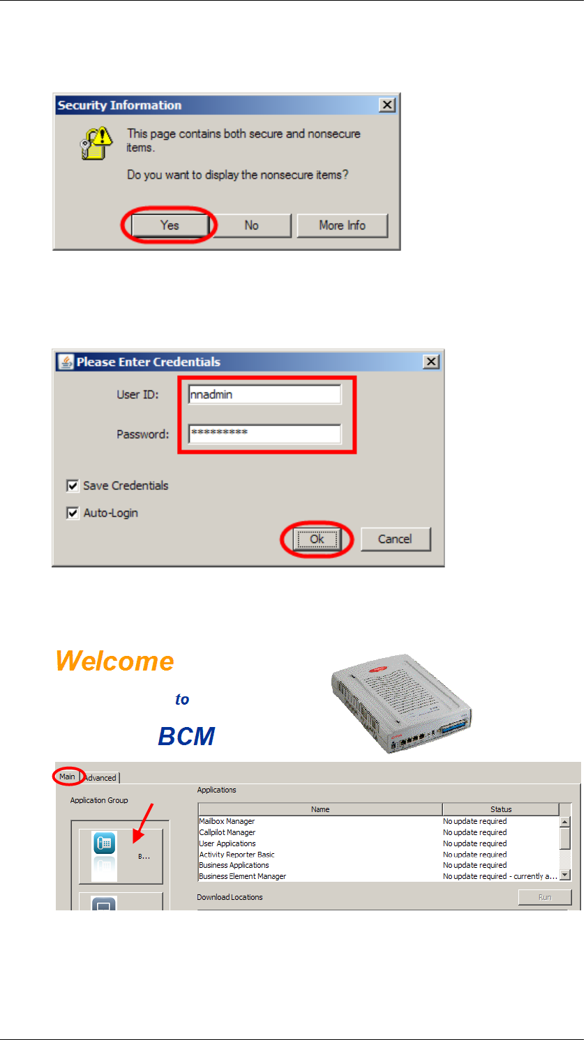
BCM450 Hardware & Installation
NN40011-001 Issue 1.2 BCM450 Rls 6.0 87
4. Accept any further security messages that you may get presented
with.
5. You will now see the login screen, enter your BCM User name and
Password. By default these are set to User ID: nnadmin Password:
PlsChgMe! Click on OK.
6. In the Welcome to BCM window, ensure the Main tab has been
selected, and the BCM button clicked.
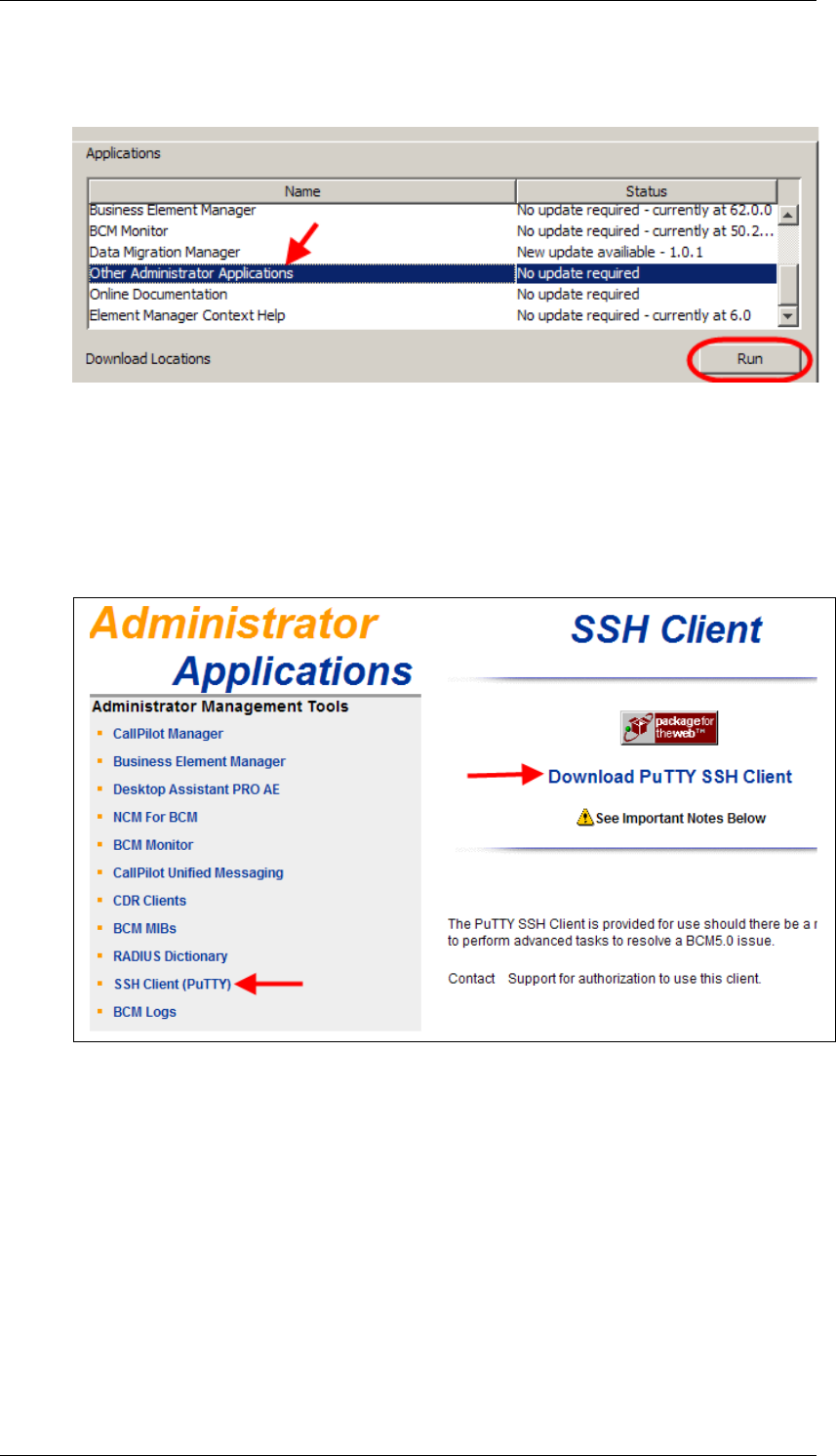
BCM450 Hardware & Installation
88 NN40011-001 Issue 1.2 BCM450 Rls 6.0
7. From the Applications list, select Other Administrator Applications
and click Run.
8. Again, accept any security messages that appear, and if prompted
enter any login details.
9. The Administrator Applications screen will be displayed.
10. In the Administrator Applications window, click on the SSH Client
(PuTTY) link, followed by Download PuTTY SSH Client.
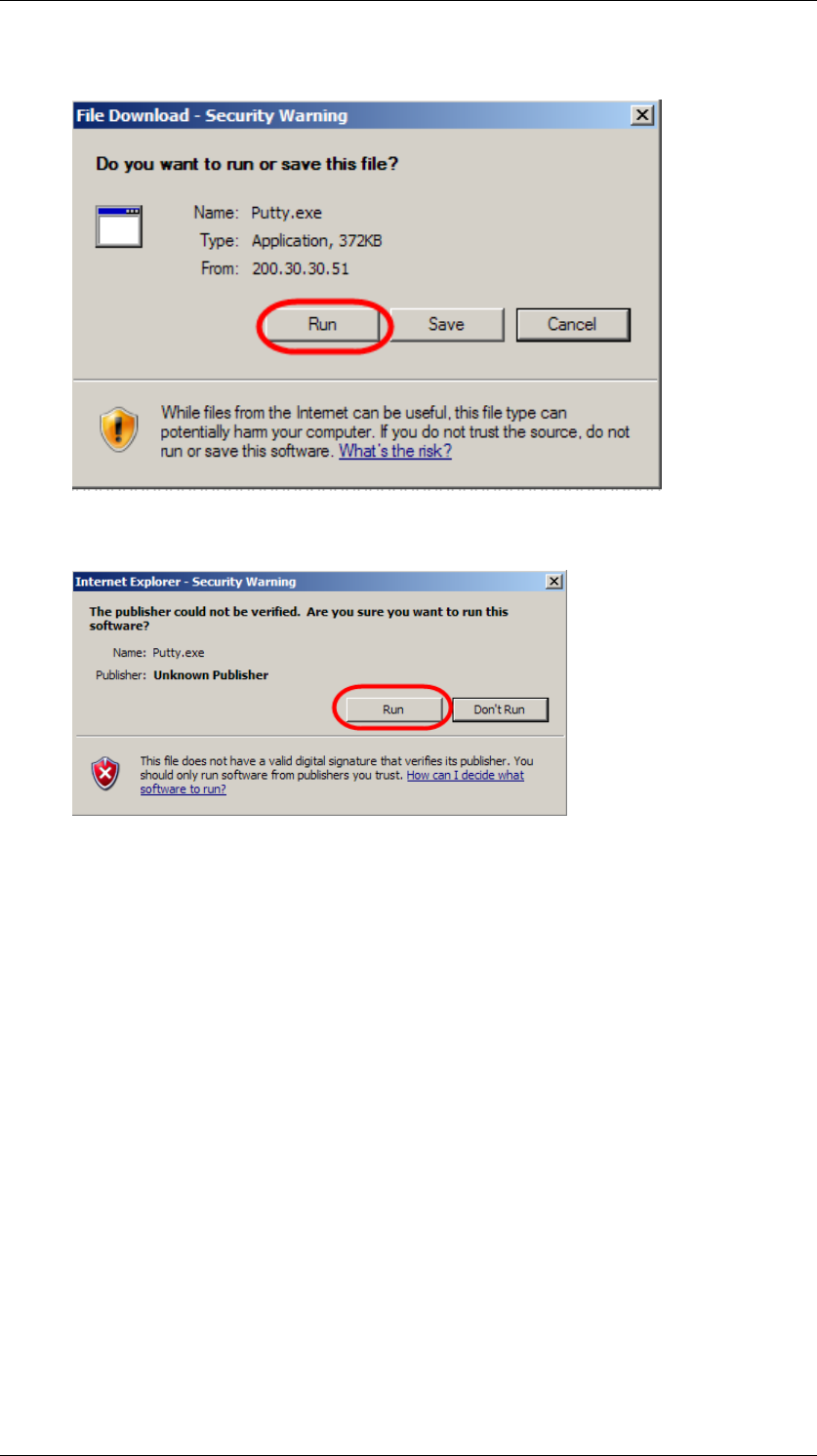
BCM450 Hardware & Installation
NN40011-001 Issue 1.2 BCM450 Rls 6.0 89
11. Click on the Run button to install the application.
12. Click on Run again.
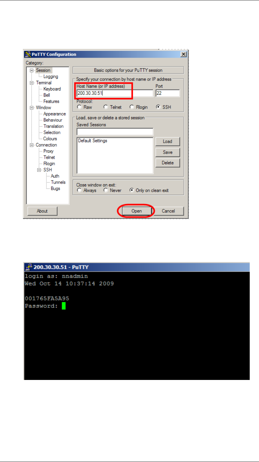
BCM450 Hardware & Installation
90 NN40011-001 Issue 1.2 BCM450 Rls 6.0
13. When installed, the PuTTY program will automatically launch. Enter
the IP Address of the BCM in the Host Name (or IP Address) field,
and click Open.
14. You must now login to the BCM with Administrator credentials. Type in
the user name after login as: and press the Enter key on your
keyboard. Then type in the password, again followed by Enter.

BCM450 Hardware & Installation
NN40011-001 Issue 1.2 BCM450 Rls 6.0 91
15. You will then be presented with the CLI. Make your selections as
described in the Configuration CLI or Maintenance CLI sections of
this guide.
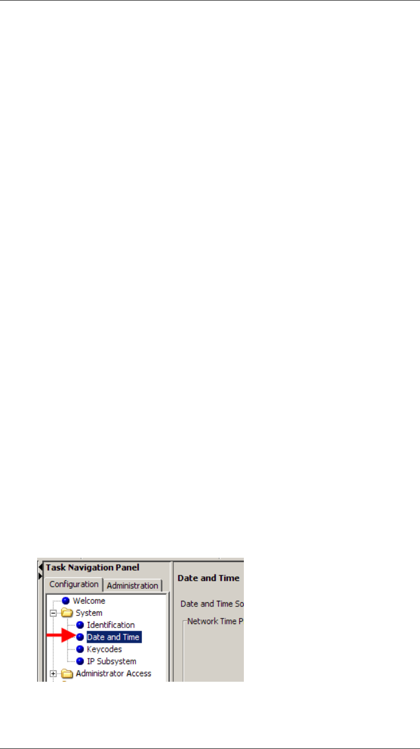
BCM450 Hardware & Installation
92 NN40011-001 Issue 1.2 BCM450 Rls 6.0
Upgrading to BCM Rls 6.0
BCM450 Rls 1.0 or 5.0 can be upgraded to BCM450 Rls 6.0 via a simple
process. After performing the upgrade, it is recommended that you apply the
Factory Image to ensure that if a Software Reset is performed, the BCM does
not revert to its previous software version.
Pre-Upgrade Activities
Before commencing the upgrade procedure, it is recommended that you
perform the following actions:
Create a backup of your current BCM configuration. If the upgrade
process fails, you should be able to retrieve the configuration. Refer to
the Backup and Restore Guide for further information.
Obtain a keycode file with the upgrade entitlement. This will need to be
applied to the BCM prior to performing the upgrade.
Obtain the Upgrade and Factory Image files. If they are still zipped,
extract them to a suitable location from which the BCM can access. A
suitable location could be:
o Your PC/laptop (i.e. the PC/laptop performing the upgrade via
Element Manager)
o A network folder accessible to the BCM
o A FTP server
o A http or https server
o A USB memory stick
Checking the Time Zone is Set Correctly
Before any upgrade is performed, you should check that the Time Zone has
been changed from the initial default setting, to the Time Zone of your locality.
If the Time Zone is still set to Factory Default, it will not be possible to apply
the upgrade files.
Use the following procedure to check the Time Zone setting.
1. In the Element Manager Configuration tab, open the System folder
and select Date and Time.
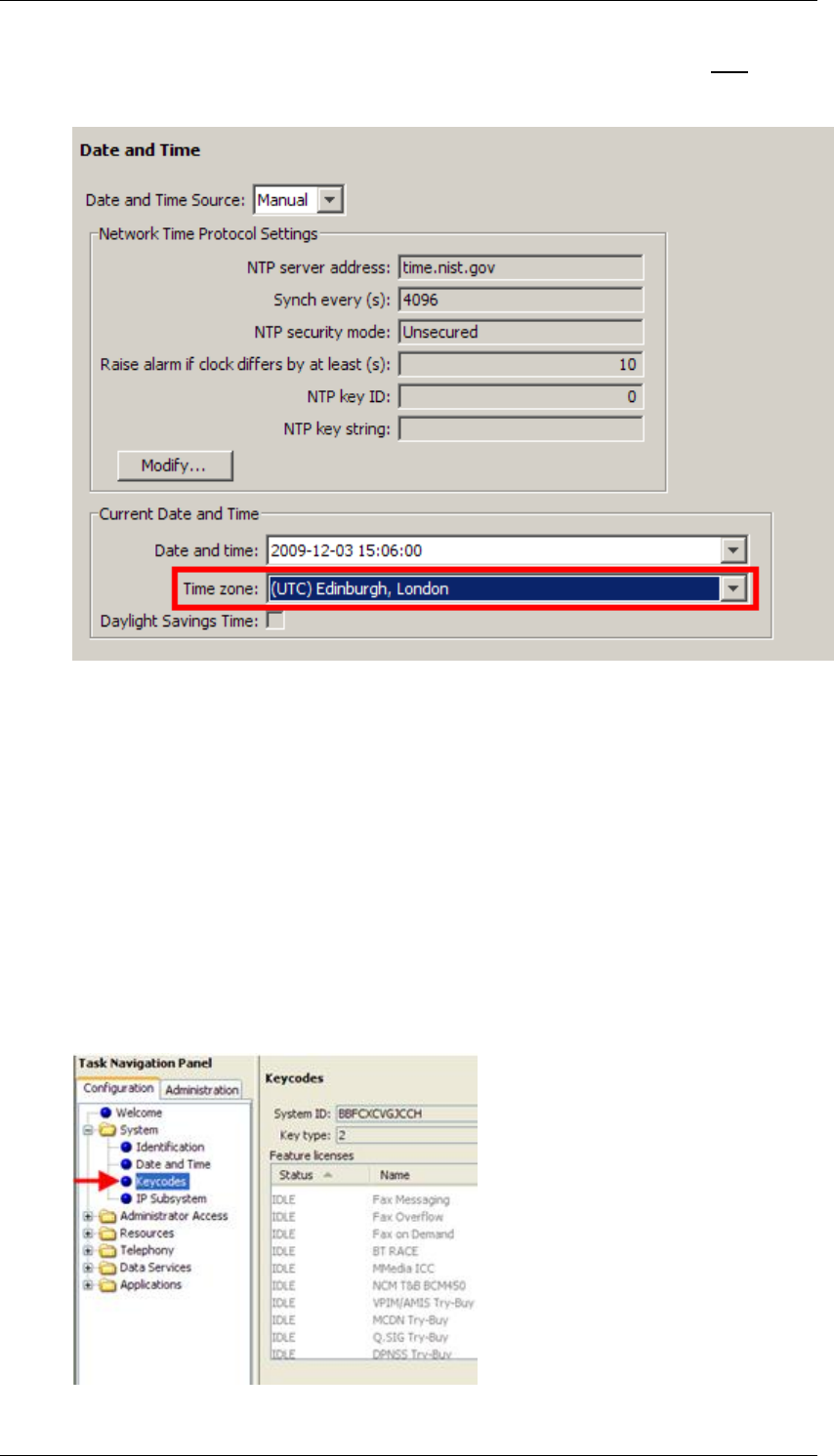
BCM450 Hardware & Installation
NN40011-001 Issue 1.2 BCM450 Rls 6.0 93
2. Check that the Time Zone field is set to your region, and is not set to
Factory Default.
3. If the Time Zone is still set at Factory Default, select the correct Time
Zone for your region.
Applying the Keycode File
A keycode file containing the upgrade authorisation entitlement (upgrade to
Rls 6.0) should be applied to the BCM before applying the upgrade files.
When you have obtained the keycode file(s) containing the appropriate
upgrade entitlement, apply the keycode using the following procedure.
1. In the Element Manager Configuration tab, open the System folder,
and click on Keycodes.
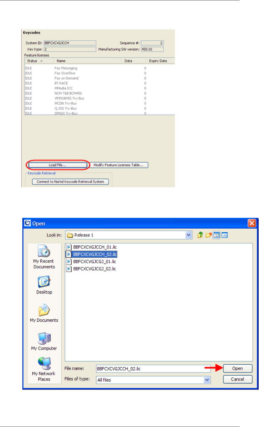
BCM450 Hardware & Installation
94 NN40011-001 Issue 1.2 BCM450 Rls 6.0
2. Click on the Load File button.
3. Browse to the location of the file and select it.
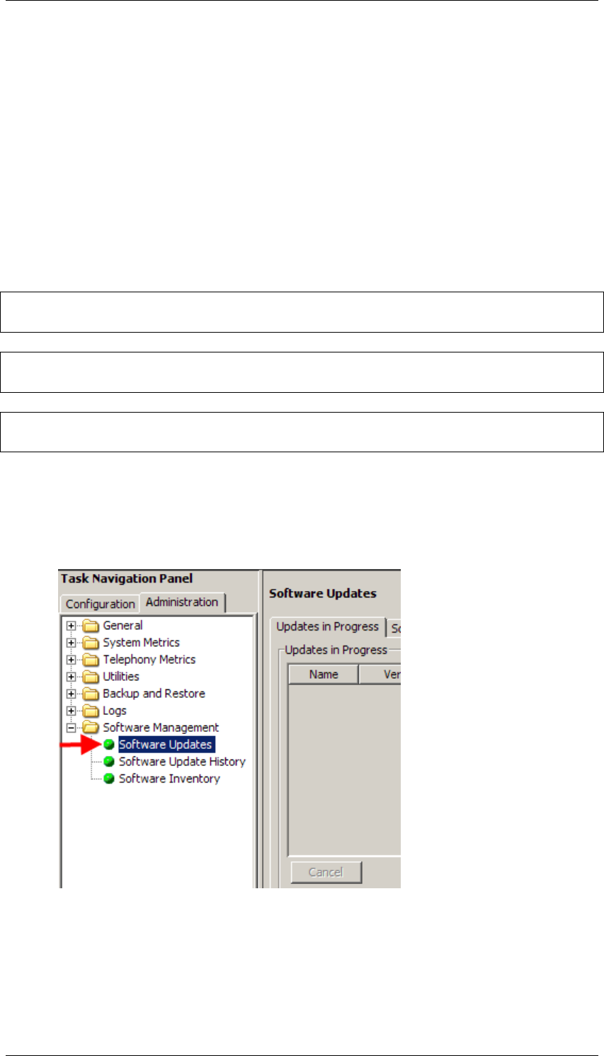
BCM450 Hardware & Installation
NN40011-001 Issue 1.2 BCM450 Rls 6.0 95
4. Click Open.
5. The new keycode file will be applied to the BCM, allowing the software
upgrade to be performed.
Performing the Upgrade
You may receive your upgrade files on DVD or in zip format. If your files are in
zip format, ensure they are extracted to an accessible location before
proceeding with the upgrade.
Note: If the keycode containing the relevant upgrade entitlement has not been
applied to the BCM, you will not be able to perform the upgrade.
Note: The upgrade process can take up to 30 minutes, during which some or
all of the BCM services will be unavailable.
Note: Do not interrupt or power down the BCM during the upgrade process,
as this could cause catastrophic failure to the BCM.
Use the following procedure to apply the upgrade files to the BCM.
1. In the Element Manager Administration tab, open the Software
Management folder and select Software Updates.
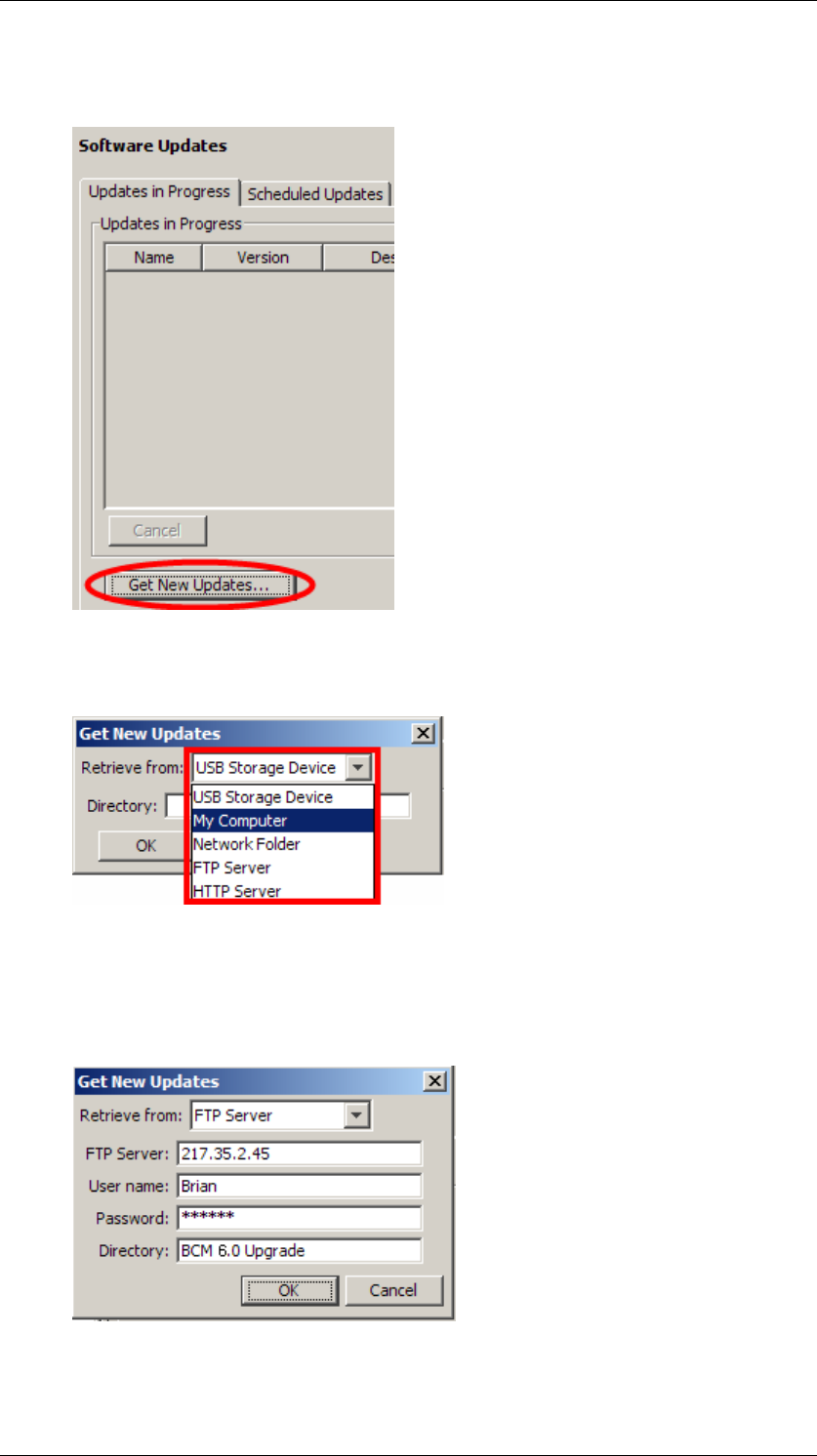
BCM450 Hardware & Installation
96 NN40011-001 Issue 1.2 BCM450 Rls 6.0
2. Click on the Get New Updates button to specify where the upgrade
files are stored.
3. In the Get New Updates dialog box, select the location of the upgrade
files from the Retrieve from drop-down list.
4. For Network Folder, FTP Server, and HTTP(s) locations, enter the
location details of the upgrade files, and any specific security
credentials for locations. Click OK when the details have been
entered.
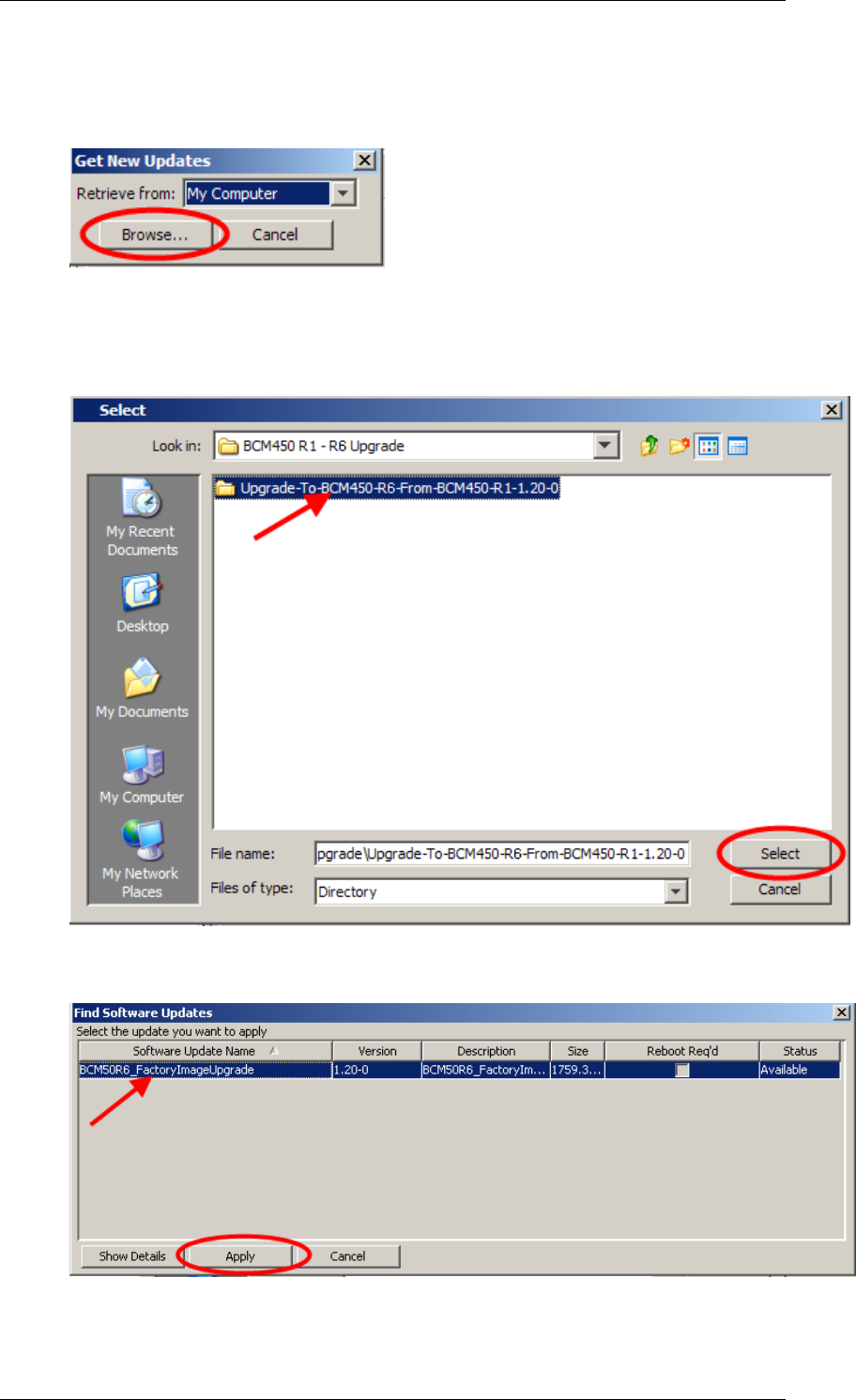
BCM450 Hardware & Installation
NN40011-001 Issue 1.2 BCM450 Rls 6.0 97
5. For the My Computer option (i.e. the upgrade files are stored on your
PC/laptop from which you‘re performing the upgrade), click on the
Browse button.
6. Navigate to the folder containing the extracted upgrade files. Click on
the folder itself (you do not need to select any specific or individual
files) and click on Select.
7. Click on the appropriate upgrade, and click on Apply.
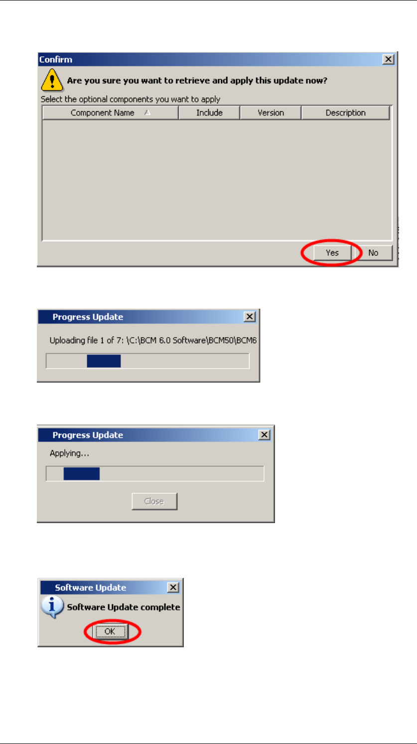
BCM450 Hardware & Installation
98 NN40011-001 Issue 1.2 BCM450 Rls 6.0
8. Click Yes in the Confirm window.
9. The upgrade files will then be uploaded to the BCM.
10. When uploaded, the files will be applied.
11. When the upgrade is complete, a confirmation box will display. Click
OK.
12. The system may automatically reboot if this is a requirement of the
upgrade.

BCM450 Hardware & Installation
NN40011-001 Issue 1.2 BCM450 Rls 6.0 99
Applying the Factory Image
When the BCM has been upgraded it is highly recommended to apply the
Factory Image. Applying the Factory Image will ensure that the BCM software
version will not revert to it‘s original state, if a Software Reset (also known as
a Level 2 Reset) is performed on the BCM.
The Factory Image is applied using the same method as applying the upgrade
files, i.e. in the Administration tab under Software Management, Software
Updates. Refer to the Performing the Upgrade section for details of how to
apply software updates.
Application of the Factory Image does not stop any BCM services or require a
reboot of the system.
Note: Do not apply the Factory Image unless you are sure the upgraded
system is functioning correctly. You will not be able to perform a Software
Reset and restore a previous backup if the Factory Image is applied before
checking system functionality.
Post-Upgrade Activities
Below is an overview of activities once the BCM has been upgraded to BCM
Rls 6.0, and the Factory Image has been applied:
Apply any new patches, e.g. from the Smart Update DVD.
Re-install client applications, including Element Manager. Refer to the
relevant documentation for further information.
Configure any new BCM Rls 6.0 features that you require (keycodes
may be necessary to unlock some features).

BCM450 Hardware & Installation
100 NN40011-001 Issue 1.2 BCM450 Rls 6.0
Avaya Documentation Links
Installation – System
Upgrade Guide
